Abstract
In this paper, a method of generating controllable spikes utilizing symmetric semiconductor ring lasers (SRLs) is investigated, and various optical behaviors of biological neurons are successfully emulated on a faster timescale. We demonstrate the synchronized spike phenomena in two directions, generated in both the clockwise (CW) and counterclockwise (CCW) modes of the tunable laser (TL)-injected SRL. The size of the peaks and the interval between them can be manipulated by adjusting the output complex amplitude of the TL and bias current. At the same time, we also analyzed the CW mode of the TL-injected SRL and successfully replicated the four distinct discharge patterns of biological neurons. These findings offer promising prospects for future neuromorphic research.
1. Introduction
In the modern information society, the need for faster and larger capacity information processing is escalating across all sectors. However, traditional computers, operating on serial instructions, fall short in achieving parallel computing, leading to numerous challenges. To address the inefficiencies, high energy consumption, and limited storage capacity of conventional computers, scientists are striving to develop a new generation of computers that can cater to the demands of our future society. The human brain, an ideal computing model capable of real-time thinking, calculation, and body operation control, has become a focal point of study [1]. Consequently, many nations have strategically prioritized research on brain emulation [2,3,4,5,6].
Photonic neuromorphic computing is a computing approach combined with brain science [7], leveraging the inherent multi-dimensionality, ultra-high speed, and large bandwidth of photons. It also incorporates the high efficiency, low power consumption, and bio-inspired characteristics of brain-like computing. This method finds extensive applications in artificial intelligence, neuroscience, and edge computing. The spiking neural network represents a key approach for realizing photonic neural morphology, considered as the third generation of artificial neural networks [8]. Serving as the fundamental unit of spiking neural networks, spiking neurons can emulate the operational mode of biological neurons, transmitting chemical or electrical signals. This novel neuron model operates approximately nine orders of magnitude faster than biological neurons, thus garnering significant attention.
Numerous teams both domestically and internationally are currently conducting extensive research in the field of photonic neural morphology, with a primary focus on two aspects: optical neural networks [9,10] and optical neural components [11]. Semiconductor lasers, due to their high-speed performance, superior controllability, high energy density, and high spatial resolution, have become an essential tool in the study of optical spiking neurons. It has been demonstrated that semiconductor lasers can display a variety of properties that are similar to those observed in neuronal systems, including excitability [12,13,14] and nonlinear dynamics [15,16]. These studies lay solid groundwork for the evolution of photonic neuromorphic computing and pave the way for the realization of more efficient low-power computing methods. As technology continues to advance, photonic neuromorphic research based on semiconductor lasers is anticipated to exhibit broader application prospects across diverse fields.
In the exploration of optical spiking neurons based on optical devices, Vertical-Cavity Surface-Emitting Lasers (VCSELs) and Distributed Feedback Semiconductor Lasers (DFB-SLs) are the primary subjects of research. Nahmias, M. et al. have investigated the integrality, threshold characteristics, and refractory period of neuron models simulated by VCSEL-SA lasers and DFB lasers [17,18,19]. Hurtado, A. et al. have conducted both theoretical and experimental studies on the photonic neural morphology of VCSEL polarization dynamics, which includes the excitability of simulated neurons [20], the controllable propagation of pulse spikes [21,22], and threshold characteristics [23]. Ma, B. et al. proposed a scheme for passive micro-ring optical spiking neurons based on DFB [24,25]. Xiang, S. et al. have examined the output of the excited response spike dynamics of VCSEL neurons [26], and established a physical model of a ‘photonic neuron-synapse-learning algorithm’ based on VCSEL [27].
Beyond the research on VCSELs and DFB-SLs, other types of lasers can also fulfill the basic functions of simulated neurons. These include quantum dot SLs [28,29,30], semiconductor ring lasers (SRLs) [31], micro-disk lasers [32], and micro-pillar lasers [33,34]. Kelleher, B. et al. successfully simulated the excitation response of quantum dot lasers [29]. Coomans, W. et al. were the first to study the optical spiking neurons of SRLs, achieving the excitation of multiple spikes with a single stimulus [31]. Additionally, Alexander, K. et al. examined the threshold characteristics of micro-disk lasers [32]. However, compared to DFB-SLs and VCSELs, these laser types are still in the preliminary stages of optical spiking neuron research. Future investigations will need to address the limitations of these laser types and further explore the potential of other laser types to realize more efficient and low-power optical spiking neurons.
In this study, we have examined the clockwise (CW) and counterclockwise (CCW) modes of TL-injected SRLs and demonstrated that SRLs can achieve various controllable and repeatable spiking modes. By manipulating the injection signal and bias current, we can amplify the magnitude of the output spikes. Furthermore, we have also explored the CW mode of the TL-injected SRLs and successfully simulated four types of neuronal discharge: rebound spiking, phasic spiking, sub-threshold oscillation, and tonic spiking. It is worth noting that the two structural configurations are fundamentally identical, enabling the realization of multiple functions of the VCSEL with a single laser. This work validates the feasibility of using SRL to simulate neurons, and presents promising prospects for the application of SRLs in computation and artificial neural networks.
2. SRL Triggers Spike
2.1. Theoretical Model
Figure 1 illustrates the system structure of the TL injected into both the CW and CCW modes of the SRL. TL is characterized by its adjustable wavelength, high precision, and excellent stability, thereby providing continuous and stable signals for the SRL. The output light, after traversing the polarization controller PC, undergoes external modulation by the MZ modulator and SG. This modulation is achieved by inducing a brief 50% power drop in the injected light, the duration of which is specified in the subsequent simulation. The modulated light, after passing through PC2, is divided into two beams by a 50/50 fiber coupler and injected into the two inputs of the SRL. The output light from the SRL is then transformed into an electrical signal via a photodetector, which is ultimately visualized on an oscilloscope. It is important to note that PC1 serves to maximize the output power of the MZ modulator, while PC2 is used to control the polarization of the injected signal to maximize the field interaction. In the simulation, we disregard any noise and temperature disturbances to the system.
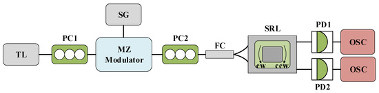
Figure 1.
The system structure diagram of TL injection into SRL CW and CCW modes. TL: tunable laser; PC: polarization controller; MZ: Mach–Zehnder modulator; SG: signal generator; FC: fiber coupler; SRL: semiconductor ring laser; PD: photodiode; OSC: oscilloscope.
In this model, the rate equation of SRL can be expressed as follows [35,36,37]:
Among them, CW and CCW are represented as clockwise and counterclockwise modes of SRL, respectively, and E(t) is the slow-varying complex electric field; N(t) is the carrier density; g is the differential gain coefficient of the laser; is the field attenuation rate; is the linewidth enhancement factor; k is the backscattering rate; is an asymmetric factor; for phase shift; is the injection coefficient; Einj is the slowly varying complex amplitude of the SRL injected with a TL; is the carrier decay rate; is the renormalized injection current; s is the self-saturation coefficient; and c is the cross saturation coefficient. is the angular frequency between the SRL and TL, , and is the frequency detuning of the external injection signal. The last item of Equations (1) and (2) represents the optical injection signal of the TL laser to the SRL, where the injection intensity = 10 ns−1. The disturbance intensity output by the MZ modulator is Kp. It can be understood that when the input signal intensity is A, the output signal is Kp * A after the disturbance of the Kp value. In this paper, we set the parameters as follows: = −4.5 GHz; = 100 ns−1; = 3.5, k = 0.44 ns−1; = 0.2; = 3; = 0.2 ns; s = 0.005; c = 0.01 [35,36,37].
2.2. Results Analysis
In biological neurons, a spike will not be produced unless the intensity of the given stimulation reaches a certain threshold. We examine the spike phenomenon at varying td times by altering the bias current and the slow-varying complex amplitude Einj of the SRL injected into the TL. It is important to note that we are analyzing the state of the SRL in a completely symmetrical condition, meaning the parameters of the two modes of the SRL are identical.
Figure 2 illustrates the signal waveform of the SRL output after the injection of the disturbance signal, depicted in black lines. Here, red represents the CW mode and blue signifies the CCW mode. The external disturbance commences at 50 ns, with a disturbance intensity of Kp = 0.5, a duration of td = 0.9 ns, a bias current of = 3.5, and a complex amplitude of Einj = 1.27, which corresponds to the slow change in the SRL injected with TL. As seen in Figure 2, both CW and CCW output stable signals at a consistent injection intensity, i.e., in the absence of disturbance. Upon the arrival of the disturbance signal, the SRL emits a spike. Once the disturbance is removed, the SRL resumes outputting a stable waveform. This behavior mirrors that of biological neurons: In a resting state, the neuron’s membrane potential remains stable. Upon receiving sufficient stimulation, the membrane potential escalates to the threshold, triggering an action potential. Following the conclusion of the action potential, the membrane potential rapidly decreases and reverts to the resting state.
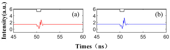
Figure 2.
At the output of CW (a) and CCW (b) modes, the output time series of td = 0.9 ns is obtained; = 3.5; Einj = 1.27; and Kp = 0.5.
This phenomenon transpires when the SRL is momentarily disengaged from the injection-locked state, emitting excitable spikes as it transitions between locked and unlocked states [22]. Unlike the spiking observed in the VCSEL, the spiking pattern in the SRL is distinguished by two well-defined dip angles separated by a peak value. The occurrence of such spikes is attributable to the metastability of the CW/CCW mode. The system enters the attraction basin of the CW/CCW and commences rotation around the CW/CCW, resulting in power oscillations. Due to its proximity to the homoclinic bifurcation point, the system maintains a stable population near the saddle point during rotation. Ultimately, the TL’s perturbation drives the SRL back into the attraction basin of the CW/CCW. This phenomenon is comprehensively explained in the referenced literature [38] through the topology of invariant manifolds.
In the waveform graph depicted in Figure 2, the injection of TL can induce a stable injection-locking phenomenon. Altering the duration of the perturbation or amplifying the injection strength of the SRL also initiates a distinct spike pattern. These spikes are comparable to the fundamental unit of spiking neural networks (SNNs)—the spiking neuron, which generates and transmits spike impulses to other neurons when the input signal surpasses the neuron’s threshold. The following describes what occurs when the perturbation time is extended under the same conditions.
When we modify the injection duration while keeping the other parameters fixed as per Figure 2, the output time series, as shown in Figure 3, demonstrates that the perturbation time length of td is set to 0.9 ns, 1.5 ns, 2.3 ns, 3 ns, and 3.7 ns, respectively. The figure reveals that under the same conditions, the number of emitted spikes increases from 1 to 5 with the increment in td. Therefore, by controlling the duration of the disturbance, single or multiple spikes can be generated on both modes. This phenomenon is shaped by the multiple folding of the unstable manifold. The laser can emit a certain number of spikes from the steady state after being triggered by a single perturbation, a process thoroughly analyzed in the referenced literature [39]. The diagram shows that the red and blue curves share the same overall change trend, i.e., the same trend is generated simultaneously under the same conditions. This is due to the bistability characteristic of the SRL, meaning that under certain conditions, two stable distribution states can coexist [40,41]. Simultaneously, the spike intensity generated by CCW is greater than that of CW. This is because the SRL exhibits unidirectional performance during DC modulation [42], indicating that at = 3.5, the intensity of the CCW mode surpasses the output intensity of the CW mode.
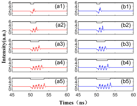
Figure 3.
The output time series with different td values from 0.9 to 3.7 ns are obtained at the output of CW (a1–a5) and CCW (b1–b5) modes. td values are 0.9 ns, 1.5 ns, 2.3 ns, 3 ns, 3.7 ns. = 3.5; Einj = 1.27; Kp = 0.5.
Figure 4 presents the numerical time diagrams of different td values (ranging from 0.9 to 3.7 ns) in CW and CCW modes. These two figures correspond to the output time series in Figure 3. Each section displays 20 superimposed time trajectories (horizontal scales 0–20 denote Figure 3a1, and so forth, with horizontal scales 80–100 denoting Figure 3a5). The x-axis represents the number of cycles, and the y-axis represents the time within the cycle. The color coding on the map gradually transitions from blue to yellow. Dark blue signifies that the output is lower than the stable state, light blue indicates a stable output, and yellow corresponds to the system’s peak. The corresponding peak response is visible in Figure 4. It is evident that two lines of dark yellow and light yellow appear under each disturbance, corresponding to the two maximum phenomena in Figure 2. As seen in the figure, CW and CCW exhibit similar shapes, indicating that they are essentially synchronized in the same state. The maximum value of color coding appears in the CCW direction (3.5), further demonstrating that the output intensity of CCW and CW varies under different bias currents.
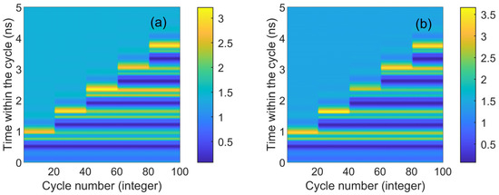
Figure 4.
The numerical time plots of different td values from 0.9 to 3.7 ns obtained at the output of the CW (a) and CCW (b) modes. td values are 0.9 ns, 1.5 ns, 2.3 ns, 3 ns, 3.7 ns. = 3.5; Einj = 1.27; Kp = 0.5.
To further investigate the characteristics of spike propagation between SRL neurons, we adjusted the system parameters to observe their influence on the spike. In Figure 5, we increase Einj to 1.6, while other parameters remain unchanged, and display the corresponding output time series. The injected signal in each case is depicted as a black line at the top. With the increase in Einj, in all instances, the height of the spike increases, and the perturbation time td required to generate the spike is also extended. It is worth noting that compared to Figure 3, the height of the second maximum in the waveform generated by Figure 5 is significantly larger than that of the first maximum. This is due to the adjustment of the injected field’s amplitude, resulting in a change in the system’s phase space waveform: the domain of attraction of the CW/CCW becomes larger, and the power oscillations generated by the TL’s perturbation remain unchanged.
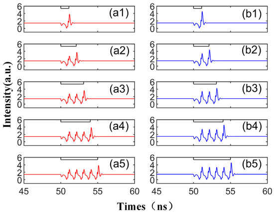
Figure 5.
Output time series with different td values from 1.1 to 5.0 ns are obtained at the output of CW (a1–a5) and CCW (b1–b5) modes. Td values are 1.1 ns, 2.1 ns, 3.1 ns, 4.1 ns, 5.0 ns. = 3.5; Einj = 1.6; Kp = 0.5.
In Figure 6, we further amplify the bias current based on Figure 5 and display the corresponding output time series. Mirroring the experimental results in Figure 3 and Figure 5, CCW and CW exhibit the same peak mode, triggering an identical number of peaks with the same intensity, time, and peak interval, thus demonstrating excellent synchronization performance. By escalating the bias current, the disturbance time td required to emit the spike decreases, and the intensity of the spike increases. As shown in Figure 6, only one peak phenomenon can be observed in a single spike period, and the other peak is very small, which is almost equal to the initial input value of the signal. In other words, by augmenting the bias current and increasing the complex amplitude Einj of the slow change of the TL injection into the SRL, the delay time td can be reduced and the spike intensity can be enhanced. At this juncture, the output waveform only has a maximum value, which differs from Figure 3 and Figure 5. This is because the CW/CCW is in a stable attraction basin. Upon the arrival of the interference at TL, the system can swiftly revert to the previous stable state.
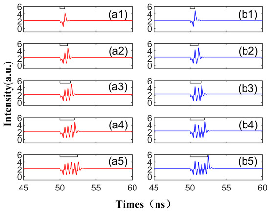
Figure 6.
The output time series with different td values from 0.65 to 2.45 ns are obtained at the output of CW (a1–a5) and CCW (b1–b5) modes. td values are 0.65 ns, 1.1 ns, 1.5 ns, 2 ns, 2.45 ns. = 5; Einj = 1.6; Kp = 0.5.
Figure 7 presents the numerical time diagrams of Figure 5 and Figure 6, employing the same color coding scheme as Figure 4. For each td value, the system’s response to 20 continuous disturbances is illustrated. Figure 7 distinctly demonstrates that the number of spikes can be regulated by altering the duration of the disturbance. Moreover, the CW and CCW modes exhibit similar trends, suggesting excellent synchronization performance between the two. Under identical parameter conditions, the peak height in the CCW mode surpasses that in the CW mode (approximately 0.5 orders of magnitude higher). Additionally, the peak height, as indicated by color coding, reaches its maximum (greater than 5.5) in Figure 7b2, which is higher than the two quantitative units in Figure 4. This indicates that augmenting the bias current size can enhance the output spike size. The two-dimensional plot reveals that as the injected current escalates, the time td needed for the system to be perturbed to produce the same spike diminishes (the maximum value of the vertical coordinate becomes smaller).
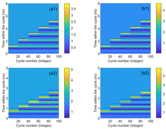
Figure 7.
Numerical time plots obtained at the outputs of CW (a1) and CCW (b1) modes for different values of td from 1.1 to 5.0 ns. td values are 1.1 ns, 2.1 ns, 3.1 ns, 4.1 ns, and 5.0 ns, respectively. = 3.5; Einj = 1.6; Kp = 0.5. Numerical time plots obtained at the outputs of CW (a2) and CCW (b2) for different td values from 0.65 to 2.45 ns. td values are 0.65 ns, 1.1 ns, 1.5 ns, 2 ns, 2.45 ns, respectively. = 5; Einj = 1.6; Kp = 0.5.
Here, we examine the time series of the CW and CCW outputs under different Kp values. To enhance visualization in a graph, we reduced the CCW output value by 4 units. We increased Kp from 0.2 to 0.85, while keeping the perturbation duration fixed at td = 2 ns. As depicted in the figure, when Kp is set to 0.2, we observe a phenomenon where the output intensity of one mode decreases while the other mode’s output intensity increases. The reason for this is that when the perturbation value is set to 0.2 times the input signal, i.e., when there is a large difference from the original signal, the bistable switches’ mode of operation occurs. As Kp further increases, as shown in Figure 8b,c, the signal exhibits four and three spikes, respectively, with Kp approaching 0.5. When Kp reaches 0.85, the modulated signal closely resembles the original signal, with insufficient intensity to generate spike signals, resulting in only slight fluctuations. From this study, we can conclude that the generation of spike signals requires an appropriate Kp value, as excessively large or small values fail to produce desirable spike phenomena.
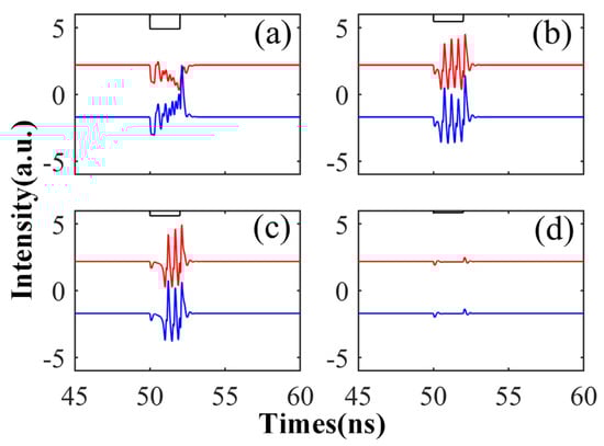
Figure 8.
The output time series of CW (red) and CCW (blue) under different Kp: Kp is 0.35 (a), 0.55 (b), 0.65 (c), and 0.85 (d), respectively. = 5; Einj = 1.6; td = 2 ns.
3. SRL Simulated Neurons
3.1. Theoretical Model
Through the simulation of the two modes of the SRL, CW and CCW, injected into the TL, we deduce that CW and CCW can concurrently generate controllable and synchronous signals under specific conditions. Following this, we simulate the system of TL injection into the SRL single mode, and examine the system’s nonlinear dynamic behavior and neuromorphic analysis.
The experimental device is depicted in Figure 9, where the polarized light of the TL is injected into the CW mode in the SRL. Unless specifically annotated, all other parameters utilized in the experiment align perfectly with those in Figure 1. The rate equation at this juncture is as follows:
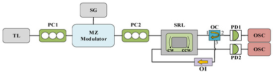
Figure 9.
System structure diagram of SRL CW mode injected by TL. TL: tunable laser; PC: polarization controller; MZ: Mach–Zehnder modulator; SG: signal generator; SRL: semiconductor ring laser; OC: optical circulator; OI: optical isolator; PD: photodiode; OSC: oscilloscope.
Among them, is the angular frequency detuning between SRL and TL, and its value is ; is the frequency detuning of the external injection signal. The rate equation of this part is the same as that of the previous part, so the detailed introduction of the parameters will not be repeated here. The parameters used in this part of the experiment are the following: = 100 ns−1; = 3.5; k = 0.44 ns−1; = 0.2; = 3; = 0.2 ns−1; s = 0.005; c = 0.01. We re-feedback the CW output signal to the CCW mode, where the feedback strength is set to kinj.
3.2. Results Analysis
Upon stimulation, biological neurons generate a spike response. This spike phenomenon primarily encompasses two types [43]: the phasic spike, where a peak emerges during the stimulation process, and the continuous spike, where a series of peak responses are produced throughout the stimulation process. Subsequently, we simulate these two phenomena observed in biological neurons using the TL injection of SRL single mode, and proceed to analyze the underlying causes.
Figure 10 and Figure 11 depict the varied responses of SRL to simulated neurons when the external stimulation time is td = 5.2 ns and the external disturbance intensity Kp = 0.5. The feedback strength kinj in Figure 10 is set to 10 ns−1. Initially, the SRL output remains stable; however, the state of CW and CCW alters when the system is subjected to external stimuli. Once the stimulation ceases, the system reverts to a stable state. This behavior mirrors the rebound spike and phasic spike observed in biological neurons. A rebound spike refers to a brief hyperpolarization of the membrane potential following a spike generated by the neuron post stimulation, which then swiftly rebounds to the resting state. The phasic spike refers to a rapid, short spike produced by a neuron after sufficient stimulation. This phenomenon can be attributed to the conversion of the external signal between the two distinct stable states of injection and locking. A peak is obtained when the system transitions from one stable state to another.
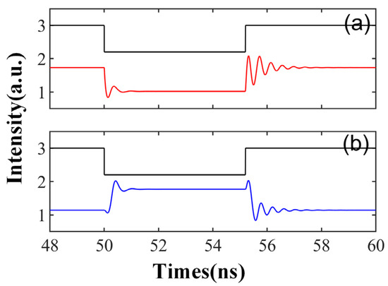
Figure 10.
The output time series of td = 5.2 ns is obtained at the output of CW (a) and CCW (b) modes. = 3.5; Einj = 1.6; Kp = 0.5; kinj = 10 ns−1.
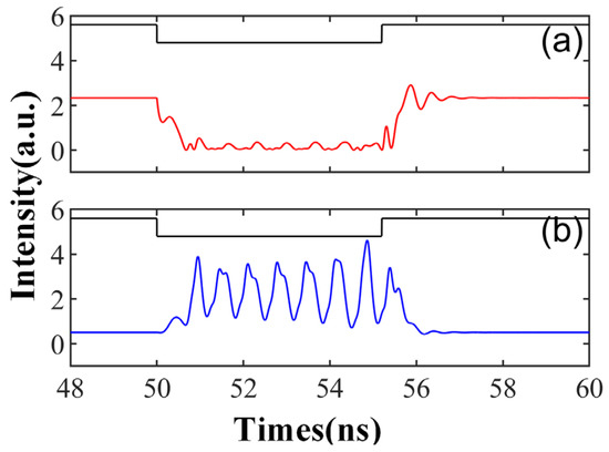
Figure 11.
The output time series of td = 5.2 ns is obtained at the output of CW (a) and CCW (b) modes. = 3.5; Einj = 1.6; Kp = 0.5; kinj = 5.5 ns−1.
Figure 11 illustrates a distinct response, characterized by periodic oscillations or peaks following the entry of the external injection signal into the system. At this time, the feedback intensity kinj is reduced to 5.5 ns−1. This mirrors the sub-threshold oscillations and tonic spikes observed in biological neurons. Sub-threshold oscillations refer to the periodic membrane potential oscillations generated by neurons upon receiving subthreshold stimulation, while tonic spikes pertain to the continuous spike discharge produced by neurons under sustained stimulation. The emergence of Figure 11 can be attributed to the relaxation oscillation phenomenon, induced by the internal parameters of the SRL and contingent on the initial condition of the external injection signal [43]. In this scenario, the oscillation of the CCW mode is not entirely suppressed, allowing the output of both modes to exhibit peak dynamic behavior.
4. Results and Prospects
In this research, we carried out a comprehensive analysis of the two modes of the TL injection SRL, observing both single and multiple spikes. We conducted numerical simulations using standard rate equations. By modulating the slow-varying complex amplitude Einj of the TL injection SRL and the bias current of the SRL, we were able to alter the magnitude of the generated spikes and the interval between peaks. Our findings indicated that by amplifying the bias current and the slow-varying complex amplitude Einj of the SRL injected by the TL, we could decrease the delay time td and enhance the strength of the spike.
Furthermore, we also emulated the CW mode of TL injection into the SRL, and turned the output of the CW around into the input of the CCW to simulate the rebound spike, phasic spike, sub-threshold oscillation, and tonic spike of biological neurons. The findings indicated that by manipulating the fundamental parameters of a laser, we successfully replicated the various behaviors of neurons. This opens up new avenues for understanding and harnessing the complex functionalities of neurons in a controlled environment.
The utilization of laser technology to implement the spike neuron model is an advanced technique that can more accurately simulate the information processing of the brain. It possesses outstanding computational efficiency and energy consumption efficiency, which contribute to enhancing the performance and intelligence of artificial intelligence systems. However, the model’s complexity and high computational demands present challenges that necessitate advanced hardware and algorithms. Currently, our understanding of the model is not yet comprehensive, highlighting the need for further research and optimization. In the realm of optical computing, implementing the spike neuron model relies on the support of optical devices and networks, which still face challenges in terms of manufacturing and integration. To drive the development of this model, it is crucial to optimize its computational efficiency and energy consumption efficiency, explore integration methods with traditional computing systems, and strengthen theoretical research. In summary, the spike neuron model holds significant potential in the fields of artificial intelligence and optical computing, but it also encounters challenges. Through continued research and development, we can effectively leverage these discoveries to propel advancements in related fields.
Author Contributions
Conceptualization, P.M.; methodology, P.M., K.W., G.L. and Y.W.; software, P.M. and K.W.; validation, P.M., K.W., G.L. and Y.W.; formal analysis, P.M., X.L., G.G. and G.H.; investigation, P.M., X.L., G.G. and G.H.; resources, P.M.; data curation, P.M. and K.W.; writing—original draft preparation, P.M. and K.W.; writing—review and editing, P.M., K.W., G.L. and Y.W.; supervision, P.M., X.L., G.G. and G.H. All authors have read and agreed to the published version of the manuscript.
Funding
This research was funded by the projects of the Natural Science Foundation of Shandong Provincial (ZR2020QF090), The Key Lab of Modern Optical Technologies of Education Ministry of China, Soochow University (KJS2066), and The Key Lab of Advanced Optical Manufacturing Technologies of Jiangsu Province, Soochow University (KJS2045).
Data Availability Statement
The authors confirm that the data supporting the findings of this study are available within the article.
Acknowledgments
The authors would like to thank all reviewers for their helpful comments and suggestions on this paper.
Conflicts of Interest
Author Xintian Liu and Gang Guo were employed by the company Yuweng Information Technology Co., Ltd. The remaining authors declare that the research was conducted in the absence of any commercial or financial relationships that could be construed as a potential conflict of interest.
References
- Fortin, D.; Aubin-lemay, C.; Bore, A.; Girard, G.; Houde, J.-C.; Whittingstall, K.; Descoteaux, M. Tractography in the Study of the Human Brain: A Neurosurgical Perspective. Can. J. Neurol. Sci. 2012, 39, 747–756. [Google Scholar] [CrossRef] [PubMed]
- Shi, L.; Pei, J.; Deng, N.; Wang, D.; Ma, C. Development of a neuromorphic computing system. In Proceedings of the 2015 IEEE International Electron Devices Meeting (IEDM), Washington, DC, USA, 7–9 December 2015. [Google Scholar]
- Poo, M.M.; Du, J.L.; Ip, N.Y.; Xiong, Z.Q.; Xu, B.; Tan, T. China Brain Project: Basic Neuroscience, Brain Diseases, and Brain-Inspired Computing. Neuron 2016, 92, 591–596. [Google Scholar] [CrossRef] [PubMed]
- Martin, C.L.; Chun, M. The BRAIN Initiative: Building, Strengthening, and Sustaining. Neuron 2016, 92, 570–573. [Google Scholar] [CrossRef] [PubMed]
- Okano, H.; Sasaki, E.; Yamamori, T.; Iriki, A.; Shimogori, T.; Yamaguchi, Y.; Kasai, K.; Miyawaki, A. Brain/MINDS: A Japanese National Brain Project for Marmoset Neuroscience. Neuron 2016, 92, 582–590. [Google Scholar] [CrossRef] [PubMed]
- Koroshetz, W.; Gordon, J.; Adams, A.; Beckel-Mitchener, A.; Churchill, J.; Farber, G.; Freund, M.; Gnadt, J.; Hsu, N.; Langhals, N.; et al. The state of the NIH brain initiative. J. Neurosci. 2018, 38, 6427–6438. [Google Scholar] [CrossRef] [PubMed]
- Sozos, K.; Bogris, A.; Bienstman, P.; Sarantoglou, G.; Deligiannidis, S.; Mesaritakis, C. High-speed photonic neuromorphic computing using recurrent optical spectrum slicing neural networks. Commun. Eng. 2022, 1, 24. [Google Scholar] [CrossRef]
- Maass, W. Networks of spiking neurons: The third generation of neural network models. Neural Netw. 1997, 10, 1659–1671. [Google Scholar] [CrossRef]
- Shen, Y.; Harris, N.; Skirlo, S.; Prabhu, M.; Baehr-Jones, T.; Hochberg, M.; Sun, X.; Zhao, S.; Larochelle, H.; Englund, D.; et al. Deep Learning with Coherent Nanophotonic Circuits. Nat. Photonics 2017, 11, 441–446. [Google Scholar] [CrossRef]
- Bangari, V.; Marquez, B.; Miller, H.; Tait, A.N.; Nahmias, M.; Ferreira de Lima, T.; Peng, H.-T.; Prucnal, P.; Shastri, B. Digital Electronics and Analog Photonics for Convolutional Neural Networks (DEAP-CNNs). IEEE J. Sel. Top. Quantum Electron. 2019, 26, 7701213. [Google Scholar] [CrossRef]
- Filipovich, M.; Guo, Z.; Marquez, B.; Morison, H.; Shastri, B. Training Deep Neural Networks in Situ with Neuromorphic Photonics. In Proceedings of the 2020 IEEE Photonics Conference (IPC), Vancouver, BC, Canada, 28 September–1 October 2020; pp. 1–2. [Google Scholar]
- Pei, S.; Tang, S.; Yan, S.; Shijin, J.; Zhang, X.; Zheng, Z. How to enhance the dynamic range of excitatory-inhibitory excitable networks. Phys. Rev. E 2012, 86, 021909. [Google Scholar] [CrossRef]
- Al Naimee, K.; Marino, F.; Ciszak, M.; Abdalah, S.; Arecchi, T. Excitability of periodic and chaotic attractors in semiconductor lasers with optoelectronic feedback. Eur. Phys. J. D 2010, 58, 187–189. [Google Scholar] [CrossRef]
- Rinzel, J.; Casades, G. Nonlinear Dynamics of Neuronal Excitability, Oscillations, and Coincidence Detection. Commun. Pure Appl. Math. 2013, 66, 1464–1494. [Google Scholar] [CrossRef] [PubMed]
- Takougang Kingni, S.; Van der Sande, G.; Gelens, L.; Erneux, T.; Danckaert, J. Direct modulation of semiconductor ring lasers: Numerical and asymptotic analysis. J. Opt. Soc. Am. B 2012, 29, 1983. [Google Scholar] [CrossRef][Green Version]
- Hurtado, A.; Quirce, A.; Valle, A.; Pesquera, L.; Adams, M.J. Nonlinear dynamics induced by parallel and orthogonal optical injection in 1550 nm Vertical-Cavity Surface-Emitting Lasers (VCSELs). Opt. Express 2010, 18, 9423–9428. [Google Scholar] [CrossRef] [PubMed]
- Nahmias, M.; Shastri, B.; Tait, A.N.; Prucnal, P. A Leaky Integrate-and-Fire Laser Neuron for Ultrafast Cognitive Computing. IEEE J. Sel. Top. Quantum Electron. 2013, 19, 1800212. [Google Scholar] [CrossRef]
- Nahmias, M.; Tait, A.N.; Shastri, B.; Ferreira de Lima, T.; Prucnal, P. Excitable laser processing network node in hybrid silicon: Analysis and simulation. Opt. Express 2015, 23, 26800. [Google Scholar] [CrossRef]
- Peng, H.-T.; Angelatos, G.; Ferreira de Lima, T.; Nahmias, M.; Tait, A.N.; Abbaslou, S.; Shastri, B.; Prucnal, P. Temporal Information Processing with an Integrated Laser Neuron. IEEE J. Sel. Top. Quantum Electron. 2019, 26, 5100209. [Google Scholar] [CrossRef]
- Hurtado, A.; Henning, I.; Adams, M.J. Optical neuron using polarisation switching in a 1550 nm-VCSEL. Opt. Express 2010, 18, 25170–25176. [Google Scholar] [CrossRef]
- Robertson, J.; Wade, E.; Hurtado, A. Electrically Controlled Neuron-Like Spiking Regimes in Vertical-Cavity Surface-Emitting Lasers at Ultrafast Rates. IEEE J. Sel. Top. Quantum Electron. 2019, 25, 5100307. [Google Scholar] [CrossRef]
- Deng, T.; Robertson, J.; Hurtado, A. Controlled Propagation of Spiking Dynamics in Vertical-Cavity Surface-Emitting Lasers: Towards Neuromorphic Photonic Networks. IEEE J. Sel. Top. Quantum Electron. 2017, 23, 1800408. [Google Scholar] [CrossRef]
- Robertson, J.; Deng, T.; Javaloyes, J.; Hurtado, A. Controlled inhibition of spiking dynamics in VCSELs for neuromorphic photonics: Theory and experiments. Opt. Lett. 2017, 42, 1560. [Google Scholar] [CrossRef] [PubMed]
- Ma, B.; Zou, W. Demonstration of a distributed feedback laser diode working as a graded-potential-signaling photonic neuron and its application to neuromorphic information processing. Sci. China Inf. Sci. 2020, 63, 160408. [Google Scholar] [CrossRef]
- Ma, B.; Chen, J.; Zou, W. A DFB-LD-Based Photonic Neuromorphic Network for Spatiotemporal Pattern Recognition. In Proceedings of the 2020 Optical Fiber Communications Conference and Exhibition (OFC), San Diego, CA, USA, 8–12 March 2020; p. M2K.2. [Google Scholar]
- Xiang, S.; Wen, A.; Pan, W. Emulation of Spiking Response and Spiking Frequency Property in VCSEL-Based Photonic Neuron. IEEE Photonics J. 2016, 8, 1504109. [Google Scholar] [CrossRef]
- Xiang, S.; Zhang, Y.; Gong, J.; Guo, X.; Lin, L.; Hao, Y. STDP-based Unsupervised Spike Pattern Learning in a Photonic Spiking Neural Network with VCSELs and VCSOAs. IEEE J. Sel. Top. Quantum Electron. 2019, 25, 1700109. [Google Scholar] [CrossRef]
- Mesaritakis, C.; Kapsalis, A. Artificial Neuron Based on Integrated Semiconductor Quantum Dot Mode-Locked Lasers. Sci. Rep. 2016, 6, 39317. [Google Scholar] [CrossRef] [PubMed]
- Kelleher, B.; Bonatto, C.; Huyet, G.; Hegarty, S. Excitability in optically injected semiconductor lasers: Contrasting quantum-well- and quantum-dot-based devices. Phys. Rev. E Stat. Nonlinear Soft Matter Phys. 2011, 83, 026207. [Google Scholar] [CrossRef] [PubMed]
- Kelleher, B.; Goulding, D.; Hegarty, S.; Huyet, G.; Cong, D.-Y.; Martinez, A.; Lemaître, A.; Ramdane, A.; Fischer, M.; Gerschütz, F.; et al. Excitable phase slips in an injection-locked single-mode quantum-dot laser. Opt. Lett. 2009, 34, 440–442. [Google Scholar] [CrossRef]
- Coomans, W.; Gelens, L.; Beri, S.; Danckaert, J.; Van der Sande, G. Solitary and Coupled Semiconductor Ring Lasers as Optical Spiking Neurons. Phys. Rev. E Stat. Nonlinear Soft Matter Phys. 2011, 84, 036209. [Google Scholar] [CrossRef]
- Alexander, K.; Van Vaerenbergh, T.; Fiers, M.; Mechet, P.; Dambre, J.; Bienstman, P. Excitability in optically injected microdisk lasers with phase controlled excitatory and inhibitory response. Opt. Express 2013, 21, 26182–26191. [Google Scholar] [CrossRef]
- Selmi, F.; Braive, R.; Beaudoin, G.; Sagnes, I.; Kuszelewicz, R.; Erneux, T.; Barbay, S. Spike latency and response properties of an excitable micropillar laser. Phys. Rev. E 2016, 94, 042219. [Google Scholar] [CrossRef]
- Barbay, S.; Kuszelewicz, R.; Yacomotti, A.M. Excitability in a semiconductor laser with saturable absorber. Opt. Lett. 2011, 36, 4476–4478. [Google Scholar] [CrossRef] [PubMed]
- Sorel, M.; Giuliani, G.; Scirè, A.; Miglierina, R.; Donati, S.; Laybourn, P.J.R. Operating regimes of GaAs-AlGaAs semiconductor ring lasers: Experiment and model. IEEE J. Quantum Electron. 2003, 39, 1187–1195. [Google Scholar] [CrossRef]
- Li, N.; Pan, W.; Xiang, S.; Yan, L.; Luo, B.; Zou, X.; Zhang, L. Bandwidth and unpredictability properties of semiconductor ring lasers with chaotic optical injection. Opt. Laser Technol. 2013, 53, 45–50. [Google Scholar] [CrossRef]
- Li, N.; Nguimdo, R.; Locquet, A.; Citrin, D.S. Enhancing optical-feedback-induced chaotic dynamics in semiconductor ring lasers via optical injection. Nonlinear Dyn. 2018, 92, 315–324. [Google Scholar] [CrossRef]
- Beri, S.; Mashal, L.; Gelens, L.; Van der Sande, G.; Mezosi, G.; Sorel, M.; Danckaert, J.; Verschaffelt, G. Excitability in optical systems close to Z2-symmetry. Phys. Lett. A 2011, 374, 739–743. [Google Scholar] [CrossRef]
- Goulding, D.; Hegarty, S.; Rasskazov, O.; Melnik, S.; Hartnett, M.; Greene, G.; McInerney, J.; Rachinskii, D.; Huyet, G. Excitability in a Quantum Dot Semiconductor Laser with Optical Injection. Phys. Rev. Lett. 2007, 98, 153903. [Google Scholar] [CrossRef] [PubMed]
- Beri, S.; Gelens, L.; Mestre, M.; Van der Sande, G.; Verschaffelt, G.; Scirè, A.; Mezosi, G.; Sorel, M.; Danckaert, J. Topological Insight into the Non-Arrhenius Mode Hopping of Semiconductor Ring Lasers. Phys. Rev. Lett. 2008, 101, 093903. [Google Scholar] [CrossRef]
- Gelens, L.; Beri, S.; Van der Sande, G.; Mezosi, G.; Sorel, M.; Danckaert, J.; Verschaffelt, G. Exploring Multistability in Semiconductor Ring Lasers: Theory and Experiment. Phys. Rev. Lett. 2009, 102, 193904. [Google Scholar] [CrossRef]
- Sorel, M.; Laybourn, P.; Scirè, A.; Balle, S.; Giuliani, G.; Miglierina, R.; Donati, S. Alternate oscillations in semiconductor ring lasers. Opt. Lett. 2002, 27, 1992–1994. [Google Scholar] [CrossRef]
- Hurtado, A.; Schires, K.; Henning, I.; Adams, M.J. Investigation of vertical cavity surface emitting laser dynamics for neuromorphic photonic systems. Appl. Phys. Lett. 2012, 100, 103703. [Google Scholar] [CrossRef]


Disclaimer/Publisher’s Note: The statements, opinions and data contained in all publications are solely those of the individual author(s) and contributor(s) and not of MDPI and/or the editor(s). MDPI and/or the editor(s) disclaim responsibility for any injury to people or property resulting from any ideas, methods, instructions or products referred to in the content. |
© 2024 by the authors. Licensee MDPI, Basel, Switzerland. This article is an open access article distributed under the terms and conditions of the Creative Commons Attribution (CC BY) license (https://creativecommons.org/licenses/by/4.0/).