Abstract
With the rapid advancement of manufacturing science and technology, the associated measurement technology has also been transformed. Traditional manual and single-instrument detection modes are unable to meet the requirements of fast beat, high precision, and online measurement in intelligent manufacturing. As connecting rods are typical and key components for automobile engines, their precision performance highly impacts the ultimate quality of engine assemblies. The online measurement of connecting rods was studied in this paper. According to the structural characteristics and parameter requirements of the connecting rods, an online multi-station measurement platform was designed and developed to measure, mark, and classify the measurements of the connecting rods in an automatic assembly line. Among these measurements, two significant parameters, the weight and the barycenter, were focused on in our work. A multi-point balance method was developed and applied to obtain the weights of the big and small ends as well as the position of the barycenter. An approach for weight sensor calibration and measurement data processing was also proposed. Finally, automatic and online measurement platforms were built for experimental verification. The results show that the measurement beats of the weight and the barycenter can reach 3 s/piece. The measured data were compared with a high-precision balance, and the average error of the connecting rod’s weight was 0.27%. The on-site application verification further proved the effectiveness and efficiency of our proposed measurement methods and machine, which enables fast and high-precision online measurement of connecting rods.
1. Introduction
With the development of digital production and intelligent manufacturing from concept to maturity and into engineering application, measurement technology in mechanical manufacturing processes is continuously being improved [1,2]. In response to the rapid development of the automobile industry, auto parts suppliers must look beyond the traditional measurement methods to meet the high-quality requirements of the whole vehicle [3,4]. New measurement concepts, processes, and systems are emerging. The measurement technology of machined precision parts, represented by automobile parts, shows the following development and evaluation trends: moving from off-line, static, single-mode, simple information-processing measurement toward online, dynamic, multi-mode, and multi-information fusion approaches [5,6,7,8].
The connecting rod is one of the core components of the engine. It connects the piston and crankshaft of the engine, and enables the rotary motion of the crankshaft connecting the rod journal with the reciprocating motion of the piston for energy output. The precision quality of the connecting rods determines the overall performance of the engine. Therefore, it is particularly important to measure and control the quality of the connecting rod. At present, many enterprises have studied online measurement technology for connecting rods. Leading companies include HOMMEL, Dr. Heinrich Schneider, ADCOLE, MARPOSS, Tokyo Precision, etc. [9,10].
Different mechanisms and methods have also been proposed for improving the measurement performance. Gao et al. built a comprehensive measurement system of connecting rods with differential inductance displacement sensors, which can simultaneously measure multiple parameters. The measurement efficiency and accuracy of the measurement system were improved to a certain extent, but there was still a gap from online measurement [11]. Yang et al. constructed a multi-parameter detection vision system for the quality of connecting rod, which provided a basis for the quality detection of connecting rod. However, the need for online measurement is not considered [12]. Xu et al. measured the inner holes of the large end and small end of the connecting rod through two measuring probes, respectively. Meanwhile, the sensors were arranged on the upper and lower planes to measure the thickness of the large end of the connecting rod. The measuring instrument improved the measuring efficiency of the connecting rod, but it failed to realize online measurement [13]. Lu et al. measured the geometric size of the connecting rod through image processing, realizing the visual measurement of the connecting rod [14]. Qian et al. used LVDT (Linear Variable Displacement Transducer) high-precision displacement sensors with the design of an automatic detection carrier, for fully intelligent online measurement of connecting rod bend and twist [15]. The measurement system in this paper was designed in view of the above shortcomings.
As a measuring station for the online measurement of connecting rods, it is necessary to comply with the global online measurement system to complete the automatic data acquisition and processing. The weight distribution and the barycenter position of the connecting rod are crucial for the smooth operation of the engine. At present, the measurement methods of the center of gravity are mostly based on the moments balance principle, including the unbalanced torque method, suspension method, and multi-point balance method [16]. The unbalanced moment method places the measured object on a frictionless fulcrum platform. If the center of gravity of the measured object deviates from the vertical axis where the fulcrum is located, an eccentricity will be generated, and then the centroid position and imbalance can be calculated according to the eccentricity [17]. The measurement principle of the suspension method is based on the two-force balance, and the center of gravity of the suspended object is located on the vertical line connected to the object [18]. The measurement principle of the multi-point balance method is based on the principle of moment balance in theoretical mechanics. According to the data collected by each sensor and the coordinate relationship between them, combined with the principle of moment balance, the weight of the object to be measured and the position of the center of gravity can be calculated [19].
In this paper, an online measurement system for connecting rods is studied and developed. The weight center of gravity of the connecting rod is detected by the multi-point weighing method. The positions of the sensors are reasonably arranged to collect the data of the connecting rod, ensuring that the measurement efficiency and accuracy can meet the online measurement requirements. Finally, the experiments verify the feasibility and effectiveness of our proposed measurement principle and methods for realizing fast and high-precision online measurements of connecting rods.
2. Connecting Rod Measurement System
2.1. Measurement Process
Connecting rods with irregular structures connect the piston and crankshaft. Moreover, there are many parameters to be measured, including straightness, distortion, weight, center of gravity, and so on. Therefore, a connecting rod online measurement system is a complex system, which integrates various types of high-precision sensors and various automatic mechanical structures. It needs to not only complete all the required measurements of the connecting rods but also seamlessly integrate with the production and other measurement processes in the automatic production line. An efficient online full inspection of the connecting rod can be facilitated. Simultaneously, the connecting rods can also be classified according to the measurement results. The system provides the basis for subsequent parts selection or repair. Moreover, the online measurement system for connecting rods can analyze the measurement data, and then feed the results back to different manufacturing processes for process improvements. As a result, a closed-loop manufacturing system for connecting rods is formed, achieving the comprehensive collection, monitoring, analysis, management, and sharing of the machining quality information of the connecting rods.
The flow chart of the connecting rod online measuring system is shown in Figure 1. The measurement system performs a series of actions and functions such as pre-inspection, weighing, measurement, calibration, marking, and classification. The connecting rods are grouped according to the weight and the tolerance of each measurement parameter, and then flow into the corresponding material channel. Firstly, the connecting rod to be measured is sent into the measuring system by the progressive feeding conveying mechanism. Then the connecting rod is transported to the feeding station. The transverse manipulator above the feeding station transfers the connecting rod to the pre-inspection station for the preliminary inspection of the connecting rod. If there is serious manufacturing deviation, the connecting rod will be pushed into the blanking channel and removed ahead of time. Otherwise, it will continue to be transferred from the transverse manipulator to the next station. When the connecting rod reaches the weight measuring station, the weight of each part of the connecting rod is measured. If it qualifies, it will go to the next station directly. Otherwise, it will be recorded before entering the next station. The function of the shape-position tolerance measuring station is to measure roundness, cylindricity, thickness, verticality, and center distance. Similarly, it will either enter the next station directly or be recorded according to its quality. The last station is the marking station. The connecting rod is marked by a laser marking machine, marking the weight, roundness, thickness, and other parameters. After marking, the connecting rod is moved to the unloading station. Finally, it enters the material dividing device for classification and grouping.
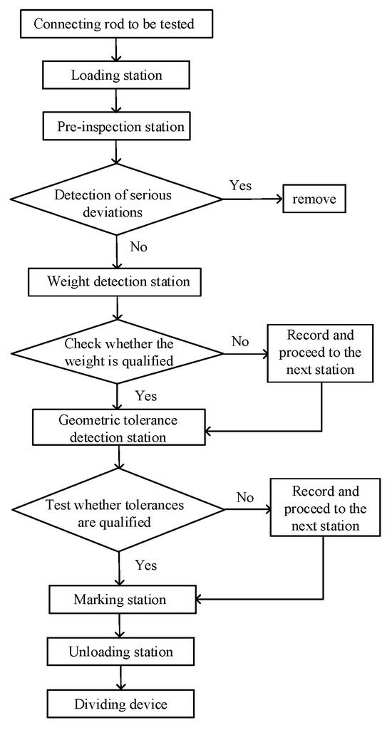
Figure 1.
Workflow of the connecting rod online measurement system.
2.2. Measurement Platform
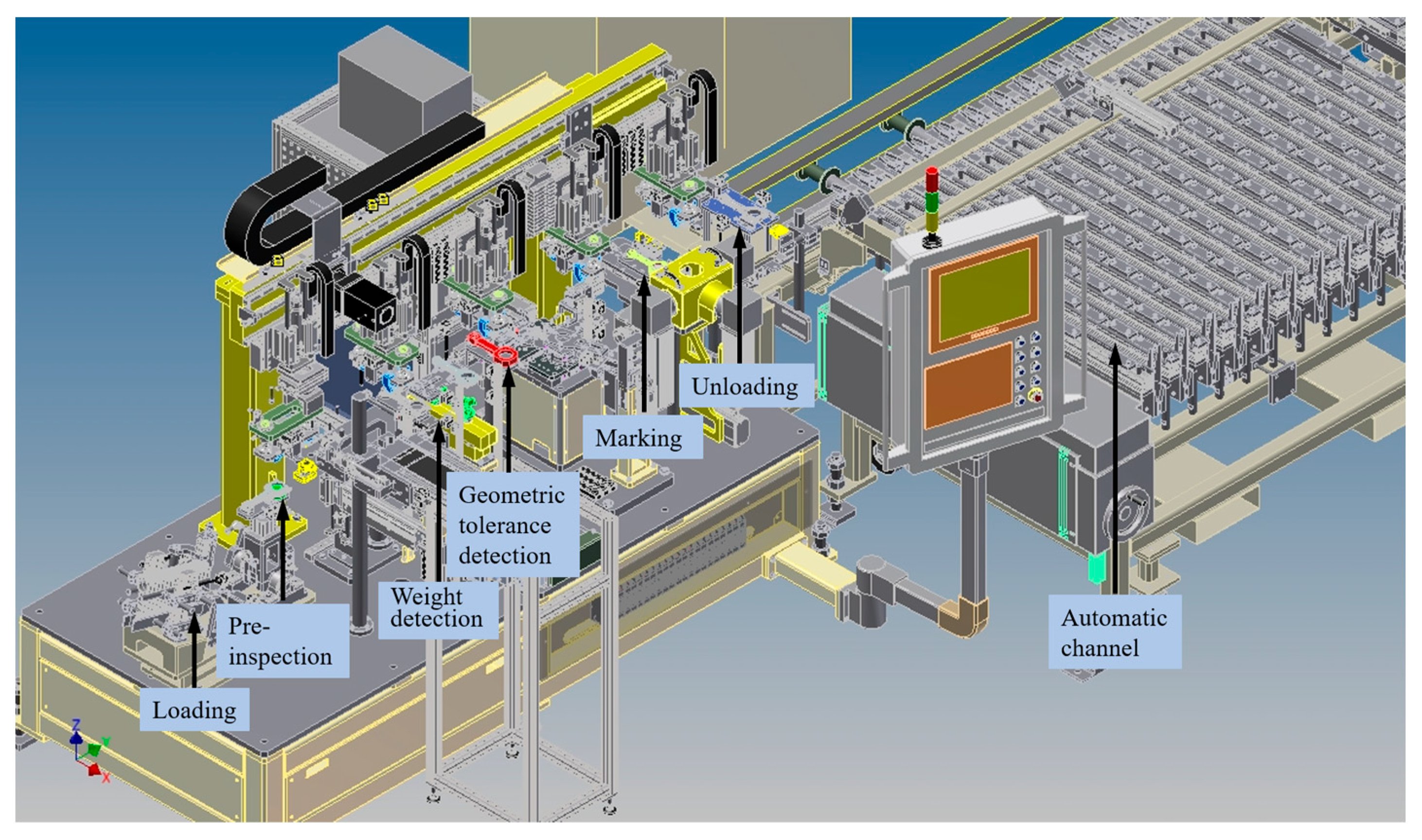
According to the abovementioned measurement processes and requirements, an online measurement system of connecting rods was designed and developed. The overall architecture is shown in Figure 2. The measurement stations were designed in sequence according to the measurement process, including the stations for loading, pre-inspection, weight detection, shape/geometric tolerance detection, marking, unloading, and automatic classification.

Figure 2.
The overall structure of connecting rod online measurement system.
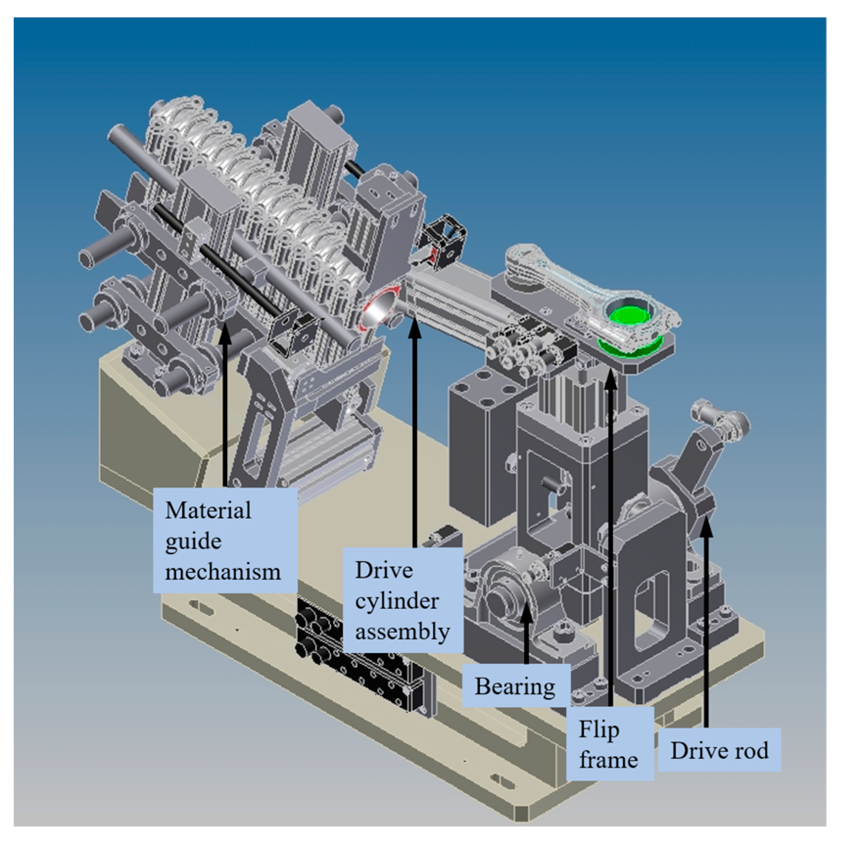
The structure diagram of the loading station is shown in Figure 3. This station is mainly composed of the material guide mechanism, the drive cylinder assembly, and the flip frame. The connecting rod processed on the production line is transmitted from the stepping material channel to the guide mechanism. The material guide mechanism slides down by the gravity of the connecting rod itself. The front end of the guide mechanism has a separator. When the measurement system is ready, the vertical state of the flip frame moves. In the meantime, the measured connecting rod on the guide mechanism is rotated and placed into a horizontal state, waiting for the grab of the material handling manipulator. This station bridges the online measurement system of the connecting rod with its production line.
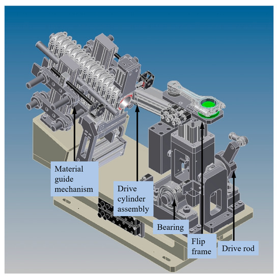
Figure 3.
Loading station structure.
The weighing station of the connecting rod is shown in Figure 4. This station is mainly composed of a lifting bracket, a positioning mechanism of the large and small ends of the connecting rod, and a measurement platform. When the connecting rod is sensed by the photoelectric switch above, the lifting bracket moves and locates the connecting rod to the positioning mechanism of the large and small ends. When the connecting rod is sensed by the photoelectric switch below, two weighing sensors measure the weight of the large and small ends of the connecting rod. The data are processed by the software system; the gravity center position and the weight distribution of the connecting rod are calculated, respectively. Then, the measured connecting rod is returned to the measurement system by the lifting bracket and sent to the next measurement station by the conveying manipulator.

Figure 4.
Connecting rod’s weight and barycenter measurement platform.
The main components of the geometrical tolerance measurement station include large and small end measuring columns, a lifting bracket, an end pressing plate, end face measuring probes, and a center distance adjusting block. When the connecting rod reaches the measuring station, it drops from the lifting bracket to the guiding column. Then, it is positioned in the measuring column at the end of the large and small head. Subsequently, the connecting rod is pressed on the measuring platform by the end-pressing plate to ensure that each connecting rod reaches the benchmark surface when measured. After positioning, various parameters to be measured are collected by the displacement sensor. The measurements of the roundness, diameter, thickness, bending, and distortion of the large and small ends are completed. A center distance adjusting block is designed in this station. For the connecting rods with different center distances, the straight-line distance between the large-end mounting plate and the small-end mounting plate can be adjusted through the center distance adjusting block to ensure the center distance. With such a design, the system can meet the requirements for the online measurement of connecting rods with different specifications. Also, such a measurement platform design can be easily extended to other applications.
Other functional structures include a marking station, a dividing device, and automatic channels. The marking station is mainly composed of a positioning fixture, laser marking head, and pneumatic slide. The connecting rod to be tested is placed on the positioning fixture by the conveying manipulator and is moved to the marking position by a pneumatic sliding table. The production information for each parameter is printed on the two sides of the connecting rod by two laser marking heads according to the requirements, such as the weight and aperture grouping of the connecting rod. The dividing device is mainly composed of a feeding trolley, linear sliding platform, pushing cylinder, and automatic feeding channel. After all the measuring and marking processes, the connecting rod is moved to the feeding trolley. According to the test results, the connecting rods are moved to different port positions through the servo linear sliding table. Then, they are pushed into the automatic feeding channel by the pushing cylinder. The transportation of the connecting rod to the tail of the feeding channel is facilitated through up and down movements of the automatic feeding channel itself. The storage rules of the feeding channel are distributed according to the measurement results of the connecting rod.
3. Connecting Rod Weight and Barycenter Measurement Method
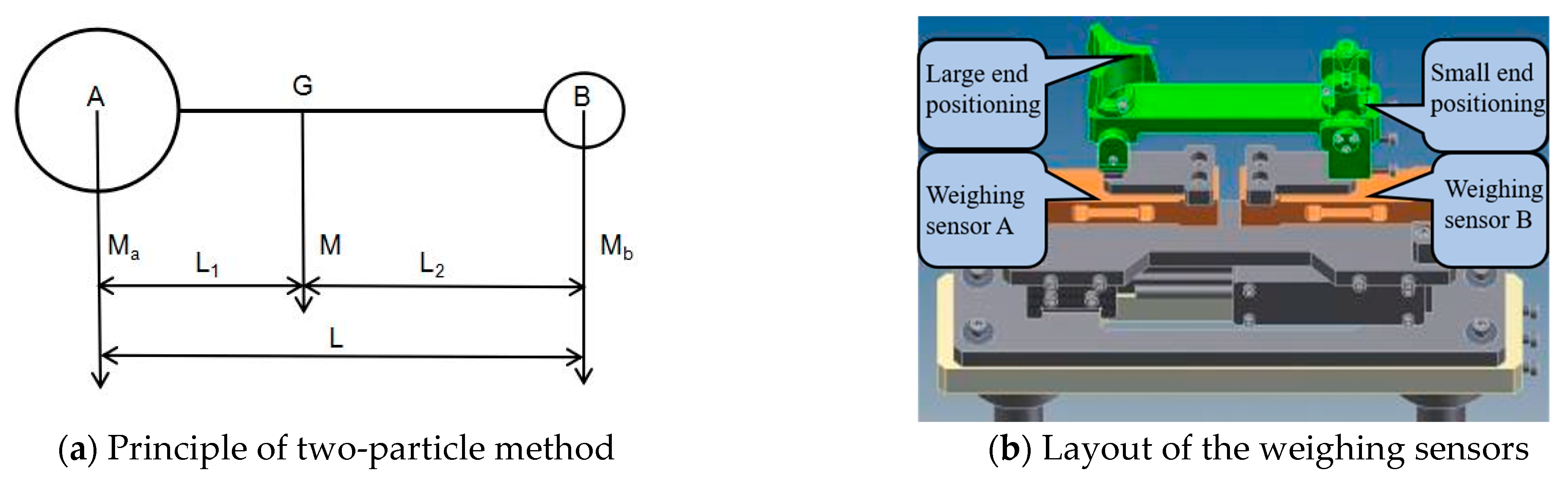
The weight and barycenter of the connecting rod are measured using the multi-point balance method. The two-particle method is used to simplify the structure of the connecting rod. The overall weight of the connecting rod is considered to be composed of two parts whose center of mass is at the center of the large and small ends. Then, the center of mass is located on the line of the center of the large and small ends. A simplified diagram of the connecting rod structure is shown in Figure 5a. It is assumed that the centroid of the large end is A, the centroid of the small end is B, and the barycenter of the connecting rod is G. Figure 5b shows the layout of the weighing sensors. Through the adapter plate, the weight of the large end of the connecting rod is transferred to sensor A by the positioning device. In the same way, the weight of the small end of the connecting rod is transferred to sensor B. Assuming that the weight of the large end is , and that of the small end is , the total weight of the connecting rod is .
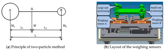
Figure 5.
The measurement principle of weight and barycenter.
Assuming that the distance between the barycenter position G of the connecting rod and the centroid A of the large end is , the distance between the barycenter position G of the connecting rod and the centroid B of the small end is , and the distance between the center of large end and small end is L. According to the multi-point balance method, the balance equation can be obtained:
As the center distance L is a known quantity, the position of the barycenter on the connecting rod can be obtained by calculation:
The above-mentioned weighing algorithm based on the multi-point balance method can enable quick and accurate measurement for the weight of each head of the connecting rod, the total weight of the connecting rod, and the position of the barycenter of the connecting rod.
4. Experimental Analysis
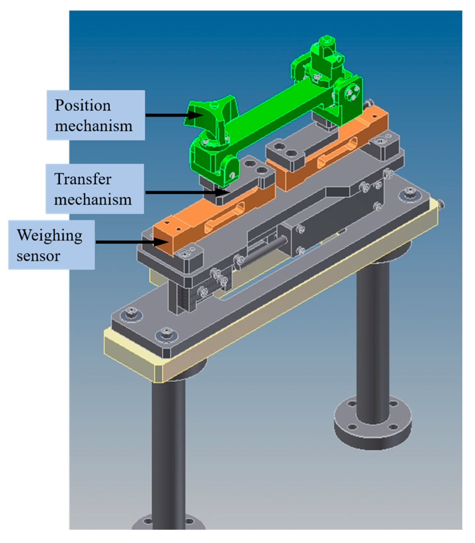
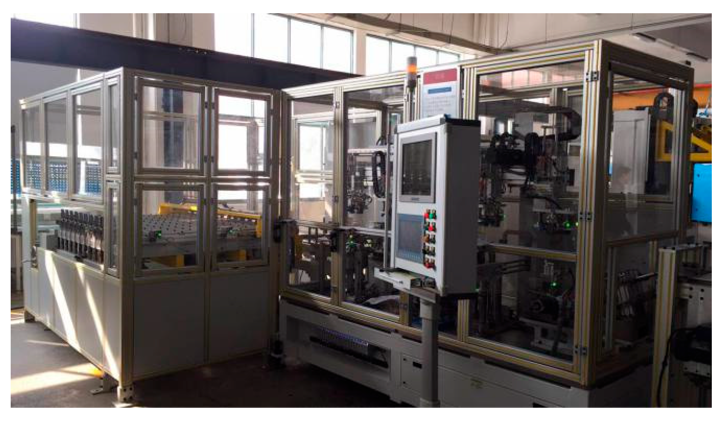
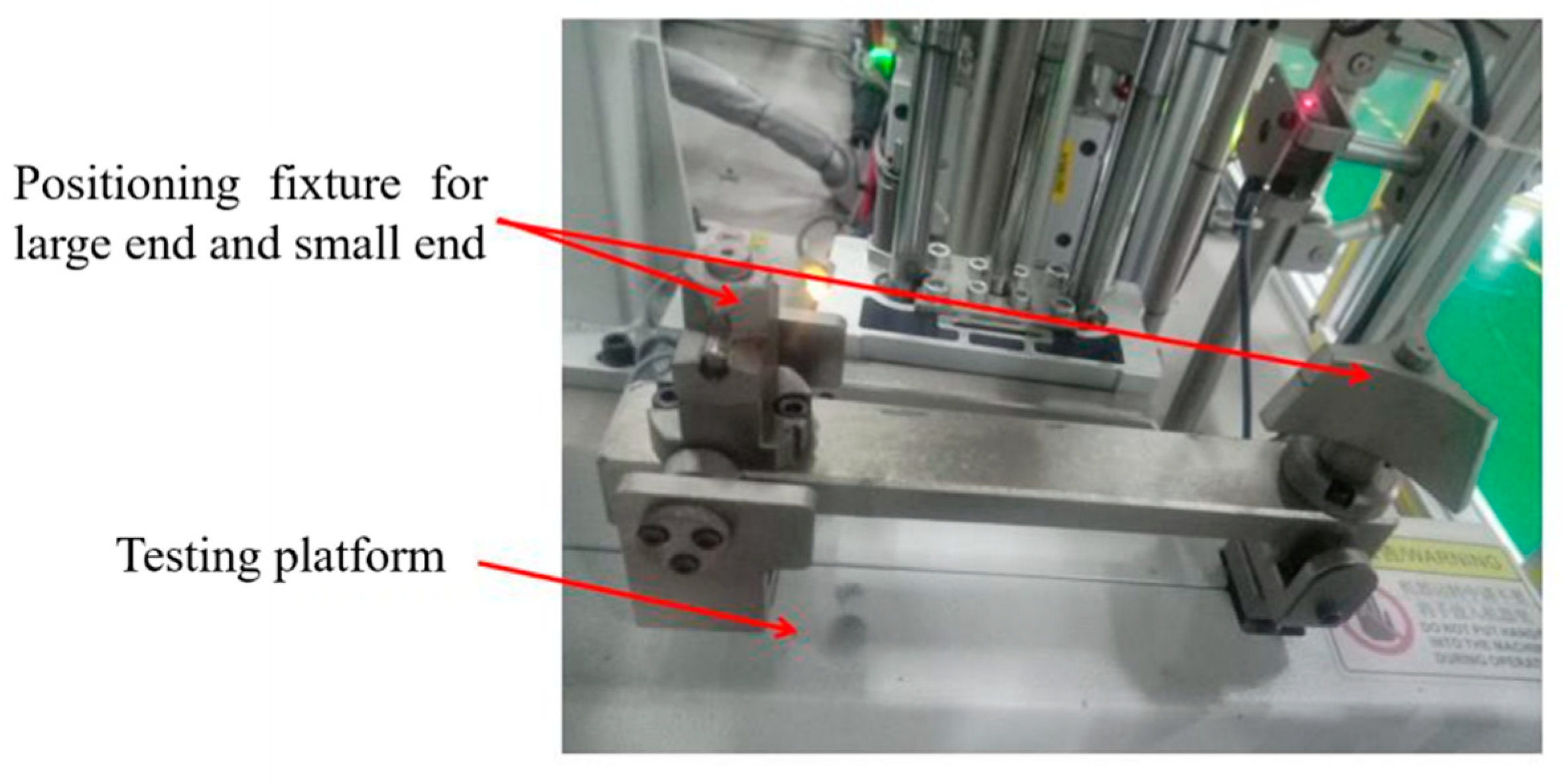
The connecting rod online measurement system needs to match the connecting rod production line site. Therefore, the demand for connecting rod measuring machines is higher than the demand for off-line ones. It is necessary to make the measurement machine capable of seamlessly connecting with the previous and post-process equipment. The developed linkage for the online measuring machine is shown in Figure 6. The communication uses the field bus TCP/IP. The hardware is an A/D for each channel, and the sampling rate is 2K. It can be freely combined, and up to 99 channels are collected at the same time. The measurement structure of the weight and center of gravity of the connecting rod is shown in Figure 7. This scheme is designed according to the principles and approaches presented in Section 2. It is mainly composed of the positioning mechanism, the transfer mechanism, and the weighing sensor. The large-end positioning mechanism of the connecting rod transfers the weight of the large end to the weighing sensor of the large end through the transfer mechanism. The same scheme is also applied to the small end. The two weighing sensors can measure the weight of the end of the connecting rod, respectively. By applying the weighing algorithm presented in Section 3, the center of gravity position of the connecting rod and the weight distribution of the end of the connecting rod can be calculated.
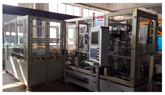
Figure 6.
Connecting rod online measurement machine.
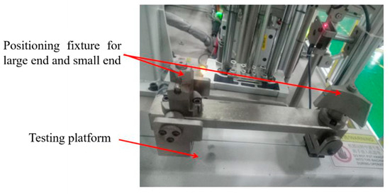
Figure 7.
Measurement structure of the weight and center of gravity.
4.1. Calibration of Weighing Sensors
The weighing sensor used in this paper is Metler Toledo MT1022, which is an aluminum single-point sensor. This sensor has a measuring range of 5 kg, a measuring repeatability accuracy of 1 g, and a resolution ratio of 0.1 g. It fully meets the online measurement requirements for connecting rod weight and barycenter.
Errors are introduced into the connecting rod online measurement system during assembly. The displacement of the positioning device makes the load-bearing point of the weighing sensor change, which results in a deviation of the weight of the connecting rod. Therefore, the weighing sensor needs to be calibrated before measurement. The input–output relationships of the two sensors are established, respectively, to further obtain the corresponding output coefficients.
The sensor is calibrated by loading the weight of standard mass at the large end and the small end. The values of the two weighing sensors are measured under no-load conditions, as shown in Table 1.

Table 1.
No-load weighing sensor values.
A weight of 500 g is loaded on the positioning part of the large end of the weighing device. The values of the two weighing sensors are recorded, respectively. Similarly, a weight of 400 g is loaded on the positioning part of the small end of the weighing device; the values of the two weighing sensors are recorded again. The measurement results are shown in Table 2.
Table 2.
Load status weighing sensor value.
Here, the output coefficient of the large-end weighing sensor is indicated by , while the output coefficient of the small-end weighing sensor is represented by . The following relationship can be obtained:
The output coefficients of the two sensors are calculated as:
According to the calculation results, the output coefficients of the two sensors are relatively small, which indicates that the installation precision of the weighing platform is relatively high and acceptable. Through calibration, the influence of the installation error on the measuring results is reduced. Consequently, the measuring accuracy of the weighing sensor is further improved.
4.2. Gross Error Elimination
Usually, there are gross errors in the process of the connecting rod’s weight and barycenter measurement. The Letts criterion is used to determine the gross error, analyze the occurrence of the gross error, filter the data collected during the measurement, and improve the measurement accuracy. The Letts criterion means that the standard deviation is set to σ for the measurement data group with only random error. According to the normal distribution of the random error, the probability of the residual drops outside ±3σ is about 0.3%. At this time, the data outside ±3σ can be considered to contain gross error, which can be eliminated [20].
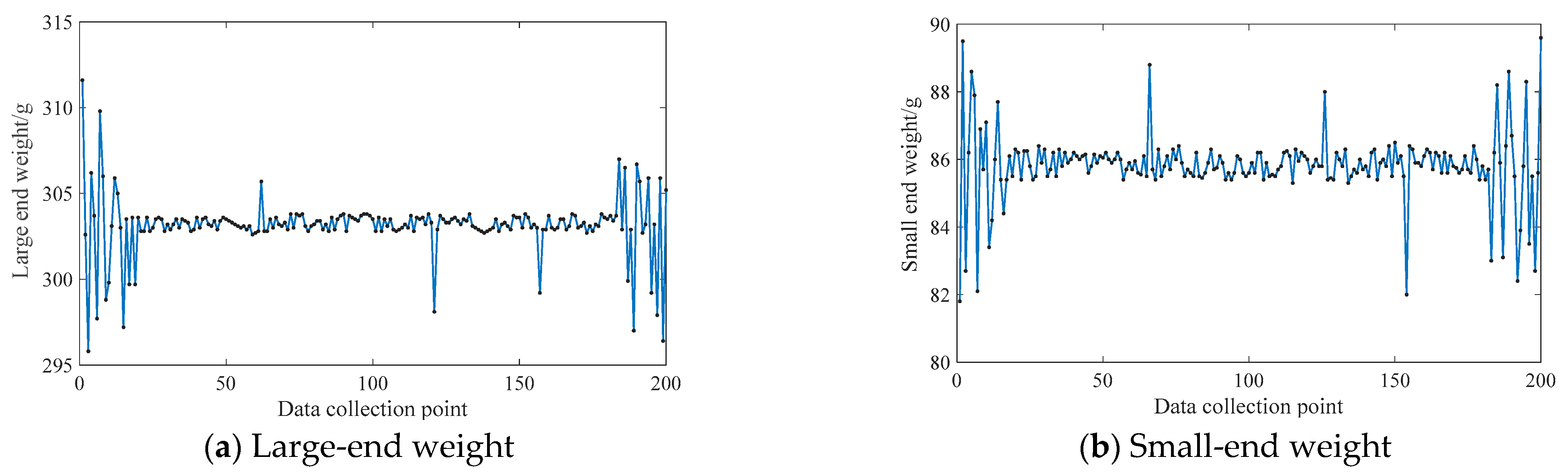
The data collected by the weighing sensor are processed using the least squares method. 200 data acquisition are collected for both the large and small ends of the connecting rod. The average value of the collected data is used as the final processing data. The output data collected by the weighing sensors in the measurement platform are shown in Figure 8a,b, respectively.

Figure 8.
Weight data of the connecting rod’s large and small ends.
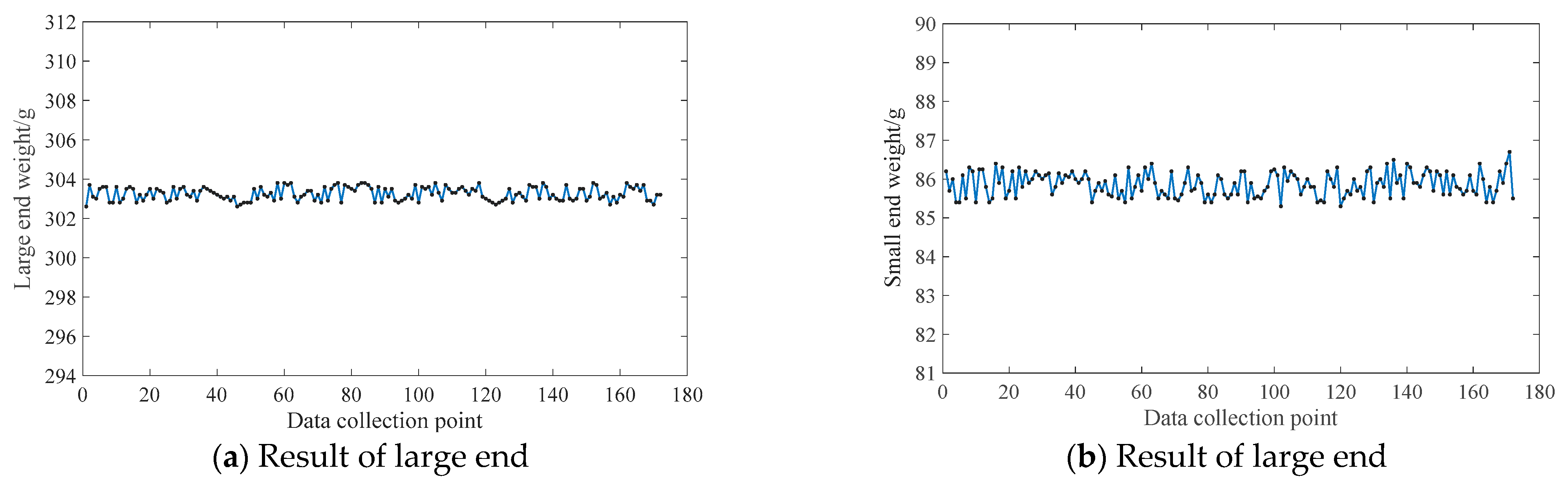
It may be seen in Figure 8 that there are gross errors in the weighing sensor when the connecting rod online measurement system is running. They are concentrated in the beginning and end stages of data acquisition. Repeated measurements of different connecting rods are carried out. The measurement results are the same as those in Figure 8. Here, the gross errors caused by the weight defects of the connecting rods are excluded. The reasons are as follows: In the beginning and end stages of the weighing process, the series of control mechanisms of the connecting rod are not in place, resulting in the corresponding vibration of the system. The collected data need to be pre-processed. The results using the Letts gross error elimination criterion are shown in Figure 9.
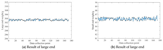
Figure 9.
Weight of connecting rod after the gross error is eliminated.
From the gross error elimination results, it can be found that the singular values in the data points are filtered, and the gross errors at the ends of the connecting rod are eliminated well. The Letts criterion is suitable for the determination and elimination of gross errors in the weight measurement of connecting rods.
4.3. Measurement of Connecting Rod Weight and Barycenter
To verify the feasibility of our proposed measurement scheme, 100 connecting rods were measured. After eliminating gross errors, the weight and barycenter were calculated. Using the measuring principle above, the weight of each end, the total weight of the connecting rod, and the barycenter position were calculated. The measurement data of 10 connecting rods were analyzed and compared randomly. The weight data and the measuring results of the measuring sensor are shown in Table 3. The minimum weight is 385.6 g, and the maximum weight is 391.3 g. The minimum distance of the barycenter is 31.1 mm, and the maximum distance of the barycenter is 32.4 mm. It shows that the online measuring machine designed in this paper has high measurement accuracy and meets the requirements of high-precision measurement.
Table 3.
Measurement results of connecting rod weight.
To further verify the accuracy of the measurement results, the experimental data of 100 connecting rods to be tested were collected. The data of 10 connecting rods randomly selected are shown in Table 4. The comparison results are shown in Figure 10.
Table 4.
Comparison of measurement results.
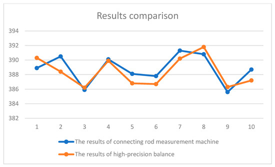
Figure 10.
Weight test results comparison.
It can be found from the graph analysis that the results of the connecting rod measurement machine are similar to the results of a high-precision balance. The maximum error is 2.1 g with a relative error of 0.54%. The minimum error is 0.2 g with a relative error of 0.05%. The average error is 0.27% (<1%). This proves the feasibility and high precision of the weight and barycenter measurement method of the connecting rod designed in this paper, and that it can adapt to a complex online environment while ensuring accuracy.
5. Conclusions
According to the structural characteristics and parameter requirements of automobile engine connecting rods, this study focused on an online measurement technology for connecting rods. Firstly, an online measurement platform was designed. The proposed multi-station scheme realizes the measurement, marking, and classification of connecting rods in turn. The measurement platform can be matched with the manufacturing rhythm of the connecting rods. It can also be easily integrated into the production line of the connecting rod to realize the online measurement of the connecting rods. Second, the measurement algorithm was also studied. The weight of large and small ends and the position of the connecting rod barycenter were obtained by the multi-point balance method. Finally, a connecting rod online measuring machine was built for relevant experimental verification.
The results of our experiments conducted on our online measurement platform are compared with the high-precision balance measurement results. The average error of the connecting rod weight is 0.27%, which meets the requirements of high-precision online measurement. The results also prove the rationality, feasibility, and effectiveness of the connecting rod online measurement scheme. The measurement accuracy and speed of our methods and machine meet the requirements of online measurement of connecting rods.
Author Contributions
Conceptualization, X.Q. and P.L.; methodology, X.Q.; software, T.G.; validation, X.Q., T.G. and P.L.; formal analysis, X.Q.; investigation, X.Q.; resources, X.Q. and P.L.; data curation, T.G.; writing—original draft preparation, X.Q.; writing—review and editing, X.Q. and T.G.; visualization, X.Q.; supervision, P.L.; project administration, X.Q. and P.L.; funding acquisition, X.Q. and P.L. All authors have read and agreed to the published version of the manuscript.
Funding
This work was partially supported by Jiangsu Province Key Research and Development Program Projects of Industry Prospect and Common Key Technology (BE20160034).
Data Availability Statement
The data presented in this study are available upon request from the corresponding author. The data are not publicly available because they are part of ongoing research and development.
Acknowledgments
Thanks to all those who supported the project and thanks to the Editor and reviewers for their useful comments.
Conflicts of Interest
The authors declare no conflict of interest.
References
- EL Ghadoui, M.; Mouchtachi, A.; Majdoul, R. Intelligent surface roughness measurement using deep learning and computer vision: A promising approach for manufacturing quality control. Int. J. Adv. Manuf. Technol. 2023, 129, 3261–3268. [Google Scholar] [CrossRef]
- Wang, Y.; Jiang, Y.; Jiang, J.; Zhang, H.; Tan, H. Key Technologies of Robot Perception and Control and Its Intelligent Manu-facturing Applications. Acta Autom. Sin. 2023, 49, 494–513. [Google Scholar] [CrossRef]
- Li, M.; Dong, W. Quality Prediction of Automotive Parts for Imbalanced Datasets. China Mech. Eng. 2022, 33, 88–96. [Google Scholar]
- Zhai, G. Optimization and Research on Quality Management of Auto Parts Supply Chain. Intern. Combust. Engine Parts 2019, 16, 224–225. [Google Scholar] [CrossRef]
- Yang, Y.; Dong, Z.; Meng, Y.; Shao, C. Data-Driven Intelligent 3D Surface Measurement in Smart Manufacturing: Review and Outlook. Machines 2021, 9, 13. [Google Scholar] [CrossRef]
- Wang, W. Applied Research of Industrial Robots in Automotive Intelligent Manufacturing Production Line. J. Phys. Conf. Ser. 2020, 1550, 042061. [Google Scholar] [CrossRef]
- Wang, H. From Traditional Manufacturing to Intelligent Manufacturing. Instrum. Anal. Monit. 2019, 4, 4–5. [Google Scholar]
- Zhang, L. Construction of Intelligent Automobile Manufacturing System Based on Industrial Big Data Collaboration. Shanghai Auto 2019, 11, 7–12. [Google Scholar]
- Marposs Co., Ltd. Optoquickset Flexible Optical Technology for Shop Use; Marposs: Bentivoglio, Italy, 2011. [Google Scholar]
- Duan, J. The Research and Development of Automobile Engine Connecting Rod Manufacturing On-Line Quality Testing Equipment. Master’s Thesis, South Chiana University of Technology in Guangzhou, Guangzhou, China, 2012. [Google Scholar]
- Gao, X. Study of Comprehensive Measuring the Geometric Parameters of Connecting Rod. Master’s Thesis, Beijing Jiaotong University in Beijing, Beijing, China, 2009. [Google Scholar]
- Yang, H.; Zhang, Y.; Cao, J. Multi-parameter Detection for Quality of Engine Connecting Rod Based on Machine Vision. Comput. Syst. Appl. 2022, 31, 129–136. [Google Scholar] [CrossRef]
- Xu, L.; Yuan, Y. The Automobile Engine Connecting Rod Assembly Measurement Instrument. In Proceedings of the Vibration and Noise Test Summit Proceedings, Beijing, China, 6–11 July 2010; pp. 102–105. [Google Scholar]
- Lu, S. Analysis of Geometric Parameters of Balance Shaft and Design of Detection System. Master’s Thesis, Shenyang University of technology in Shenyang, Shenyang, China, 2018. [Google Scholar]
- Qian, X.; Hu, Y.; Lou, P. High-precision Online Measurement Technology of Connecting Rod’s Degree of Bend and Twist. Comput. Integr. Manuf. Syst. 2022, 28, 3879–3885. [Google Scholar] [CrossRef]
- Li, Y. Research on Precision Machine Quality Centroid and Unbalance Torque Detection System. Master’s Thesis, Shenyang Ligong University in Shenyang, Shenyang, China, 2018. [Google Scholar]
- Qian, J.; Mu, J.; Hou, C. A parametric study on unbalanced moment of piston type value core. J. Zhejiang Univ. Sci. A Appl. Phys. Eng. 2021, 22, 265–277. [Google Scholar] [CrossRef]
- Li, P.; Yao, T. Gravity-Center Measurement Method for Aircraft Weight with Low-Cost. In Proceedings of the 2020 China Aviation Industry Technology and Equipment Engineering Association Annual Conference Proceedings, New Orleans, LA, USA, 30 May 2 June 2020; p. 3. [Google Scholar] [CrossRef]
- Huang, Q.; Teng, Z.; Tang, X. Weighing fusion compensation method of temperature drift for electronic analytical balance. J. Electron. Meas. Instrum. 2015, 29, 1121–1129. [Google Scholar]
- Zhang, Z.; Zhang, Z.; Hu, G.; Zhu, Z. Improved Unscented Kalman Filter Based on Gross Error Compensation Algorithm with Pauta Criterion and Linear Fitting. Comput. Meas. Control. 2019, 27, 153–156+162. [Google Scholar] [CrossRef]


Disclaimer/Publisher’s Note: The statements, opinions and data contained in all publications are solely those of the individual author(s) and contributor(s) and not of MDPI and/or the editor(s). MDPI and/or the editor(s) disclaim responsibility for any injury to people or property resulting from any ideas, methods, instructions or products referred to in the content. |
© 2023 by the authors. Licensee MDPI, Basel, Switzerland. This article is an open access article distributed under the terms and conditions of the Creative Commons Attribution (CC BY) license (https://creativecommons.org/licenses/by/4.0/).