Article

An Electric Vehicle Assisted Charging Mechanism for Unmanned Aerial Vehicles

1
Department of Computer Science & Information Engineering, National Dong Hwa University, Shoufeng, Hualien 974301, Taiwan
2
Department of Electrical Engineering, National Dong Hwa University, Shoufeng, Hualien 974301, Taiwan
*
Author to whom correspondence should be addressed.
Electronics 2023, 12(7), 1729; https://doi.org/10.3390/electronics12071729
Submission received: 31 January 2023 / Revised: 29 March 2023 / Accepted: 3 April 2023 / Published: 5 April 2023
(This article belongs to the Special Issue Electric Vehicles Integration and Control in Smart Grids)

Abstract

:
The global greenhouse effect and air pollution problems have been deteriorating in recent years. The power generation in the future is expected to shift from fossil fuels to renewables, and many countries have also announced the ban on the sale of vehicles powered by fossil fuels in the next few decades, to effectively alleviate the global greenhouse effect and air pollution problems. In addition to electric vehicles (EVs) that will replace traditional fuel vehicles as the main ground transportation vehicles in the future, unmanned aerial vehicles (UAVs) have also gradually and more recently been widely used for military and civilian purposes. The recent literature estimated that UAVs will become the major means of transport for goods delivery services before 2040, and the development of passenger UAVs will also extend the traditional human ground transportation to low-altitude airspace transportation. In recent years, the literature has proposed the use of renewable power supply, battery swapping, and charging stations to refill the battery of UAVs. However, the uncertainty of renewable power generation cannot guarantee the stable power supply of UAVs. It may even be very possible that a large number of UAVs need to be charged during the same period, causing congestion in charging stations or battery swapping facilities and delaying the arranged schedules of UAVs. Although studies have proposed the method of that employing moving EVs along with wireless charging technology in order to provide electricity to UAVs with urgent needs, the charging schemes are still oversimplified and have many restrictions. In addition, different charging options should be provided to fit the individual need of each UAV. In view of this, this work attempts to meet the mission characteristics and needs of various UAVs by providing an adaptive flight path and charging plan attached to individual UAVs, as well as reducing the power load of the renewable power generation during the peak period. We ran a series of simulations for the proposed flight path and charging mechanism to evaluate its performance. The simulation results revealed that the solutions proposed in this work can be used by UAV operators to fit the needs of each individual UAV.

1. Introduction

With the growing popularity of renewable energy and electric vehicles (EVs), the traditional way of operating the electricity grid for commercial and residential use must be adjusted. The future electricity network will include a large number of renewable energy generation facilities, power storage facilities, and EVs [1]; how to make good use of renewable energy to reduce production costs and environmental hazards has become a hot research topic in recent years [2]. In the case of solar energy, this type of renewable energy is distributed in a decentralized manner in houses or buildings owned by the prosumers. Renewable energy generation facilities may also be deployed at charging points to provide the electricity for charging electric vehicles. The electricity generated by the renewable power generation facilities provides for the electricity needs of the producers and sellers, and stores as much electricity as possible in the producers’ storage facilities and EV batteries. However, with the increasing popularity of distributed renewable energy installations, the uncertainty of distributed renewable energy generation may still cause unpredictable power shortages in a short period of time.
Most of the EVs run only during specific periods or when they are in demand, such as commuting to work or shopping on the street, and most of the time the vehicles are idle. This is why the industry continues to propose EV charging and discharging plans to supply battery power from idle EVs to the grid to reduce the grid’s peak power load when there is an imbalance between supply and demand due to a shortage of renewable energy. With the emergence of peer-to-peer power trading [3], the researchers have proposed peer-to-peer power trading mechanisms for vehicle-to-vehicle charging [4,5,6,7]. Such a more flexible charging method can be applied to EVs that run continuously for a long period of time, while effectively avoiding the aforementioned grid overload problem and providing real benefits to EV users [8].
In addition to EVs that will replace fuel vehicles as the main means of ground transportation in the world, unmanned aerial vehicles (UAVs) have recently become increasingly popular in various fields. UAVs have been widely used for numerous applications, such as extending the coverage and boosting traffic throughout cellular communication systems, extending the lifespan of wireless sensor networks, real-time road traffic monitoring, remote sensing, search and rescue operations, and military applications [9]. To name a few, Chiaraviglio et al. presented a mechanism of small cells mounted on top of the UAVs to boost the capacity in hotspot areas [10]. They proposed a model to schedule the missions of the UAVs over time, manage the amount of macro cell bandwidth consumption, control the throughput of users, and ensure the energy balance of electricity grids. In [11], an optimization model for UAV-aided cellular network was formalized to take into account all the revenue/cost terms associated to energy. The UAV missions and energy levels were modeled over time and with 3D-space domains through a graph-based approach. An efficient heuristic was proposed to reduce both the computation time and the memory occupation of five orders of magnitude compared to the aforementioned optimization model. Duong et al. gave a survey on caching models moving from the ground to the air to alleviate the high data rate and computational capability problems in 6G networks [12]. UAV caching with assisted techniques, UAV caching-enabled mechanisms, and UAV caching applications and services were presented to illustrate the role of UAV caching system in 6G networks. Chen and Liu proposed a green energy-powered base station and UAV charging mechanism to extend the lifespan of wireless sensor networks. A wireless charging pricing model was presented to calculate the profit of the charging service and a profit-driven UAV charging algorithm was developed to maximize the UAV charging profit [13].
In response to the COVID-19 epidemic in the past two years, goods delivery services have changed the face-to-face shopping habits of humans, and UAVs have recently become an important transportation tool to provide a more flexible supply chain and contactless goods delivery services during the COVID-19 epidemic. The literature even predicts that UAVs will become the main conduit for goods delivery services by 2040 9. At the same time, the weight-bearing technology of UAVs has also been proven to be able to provide passenger service, and passenger UAVs have thus attracted the industry and academia to explore the feasibility of using UAVs in transportation in the future, which will change the traditional ground transportation of human beings and use low-altitude airspace transportation as the beginning of the new ‘third dimension’ of transportation in the future world [14]. However, due to the short battery life of UAVs, the flight time of UAVs is limited, and they need to be recharged regularly. Accordingly, the battery charging of UAVs have become a popular research issue in recent years [15,16,17].
It is well known that solar power charging, battery exchange and wireless charging stations have been proposed in the literature to solve the battery endurance problem of UAVs. However, the uncertainty of solar energy cannot guarantee the power supply of UAVs [18]. Accordingly, a UAV needs to fly to a nearby charging station or battery exchange facility to replace the battery if it will deplete its battery power before reaching its destination. Although charging station planning for UAVs was proposed in the literature to maximize UAVs’ coverage range and minimize the total cost of energy and decarbonization [19], flying to a charging station or battery exchange facility for battery charging still causes an inconvenience and adds additional time and power consumption for UAVs that require constant or long-duration operation, such as logistics service and passenger UAVs. It is very likely that a large number of UAVs will need to be charged at the same time in the future. If unregulated, this could not only lead to a more serious imbalance in the supply and demand of electricity in power grids during peak hours, but also cause congestion at charging stations or battery exchange stations and affect the scheduled missions of UAVs [20,21,22]. Therefore, if UAVs are used to transport medical and pharmaceutical products, fresh fruits and vegetables, and other emergency parcel delivery services, the traditional battery charging methods of UAVs will not be affordable after the number of UAVs is significantly increased in the future. Accordingly, the UAV customers will not be able to meet the urgent demand of users to receive the items in real time. Therefore, it can be seen from the literature that new charging solutions for UAVs are continually being proposed to extend their battery lives during flight [23].
In addition to the mature static wireless charging technology used to charge the UAVs, academia and industry have been developing new dynamic wireless charging solutions to solve the inconvenience and limitation of the existing charging stations for UAVs during flight. Among them, inductive power transfer is the first choice of wireless transmission method for UAVs in order to achieve efficient power transmission in close proximity [24]. Meanwhile, the study in [25] installed wireless charging panels on moving EVs to offer the power to UAVs that are close to the UAVs’ flight paths, and thereby shortened the charging time of UAVs during their flight missions. Qin et al. proposed a mobile charging vehicle to support the charging of UAVs [26], which optimized the routing and scheduling of the UAV mission with the mobile charging vehicle. Lin et al. developed a scalable and robust approximate algorithm for planning the trajectories of energy-constrained UAVs and unmanned ground vehicles serving as mobile charging stations in persistent surveillance missions [27]. They introduced a robustness parameter in their planning algorithm to ensure that the resulting plan is applicable even when there are unknown obstacles on the ground.
Although several studies in the recent literature have conducted approaches to provide power to UAVs through wireless charging technology [23], it is very likely that numerous UAVs need to be charged during peak periods, causing congestion in traditional fixed-point wireless charging stations or battery swapping facilities and delaying the arranged schedules of UAVs. If a UAV is used to transport goods for urgent needs, it might be unable to arrive at the destination in the time requested by the customer. Although studies have proposed to employ moving EVs along with wireless charging technology to provide electricity to UAVs with urgent needs, the presented charging schemes are still too simplified and have many limitations. Specifically, although the scheme proposed in [26,27] employed mobile charging vehicles (MCVs) to offer another charging option for battery charging of a UAV, the issues of the cost of deploying a large number of MCVs in response to an increasing number of UAVs and congestion deterioration at traditional charging facilities caused by the recharging demands of MCVs during peak periods requires attention. In other words, the congestion caused by the large number of UAVs needing to be charged during peak periods at various charging facilities still exists. Thus, the problem of trip delays for UAVs on emergency missions that have a time constraint on arrival at their destination has not been effectively solved. Accordingly, there is an urgent need to develop an appropriate charging strategy that provides different charging alternatives for each individual UAV depending on its mission characteristics and needs. To the best of our knowledge, there is no literature that combines the flight path planning with the mission characteristics and charging cost of UAVs to determine a suitable flight path and charging option for individual UAVs. In view of this, this work proposes a fight path and charging scheme for UAVs to meet the task characteristics and charging needs of various types of UAVs. The proposed scheme plans the UAVs on emergency missions to be charged during peak hours without delaying their scheduled trips as much as possible. Meanwhile, UAV operators on regular missions can choose charging facilities with lower charging costs to charge their UAVs.

2. The Proposed Algorithm

This work assumes that EVs for commuting or home use will be parked at home or work most of the time, and will use plug-in charging facilities to meet their battery charging needs. It is also observed that numerous governments have initiated the projects of installing inductive wireless charging panels along EV routes to provide a dynamic wireless charging solution for moving EVs [28]. Therefore, if there is a temporary charging need on the way to the destination, a wireless road charging panel will also be available for EV charging.
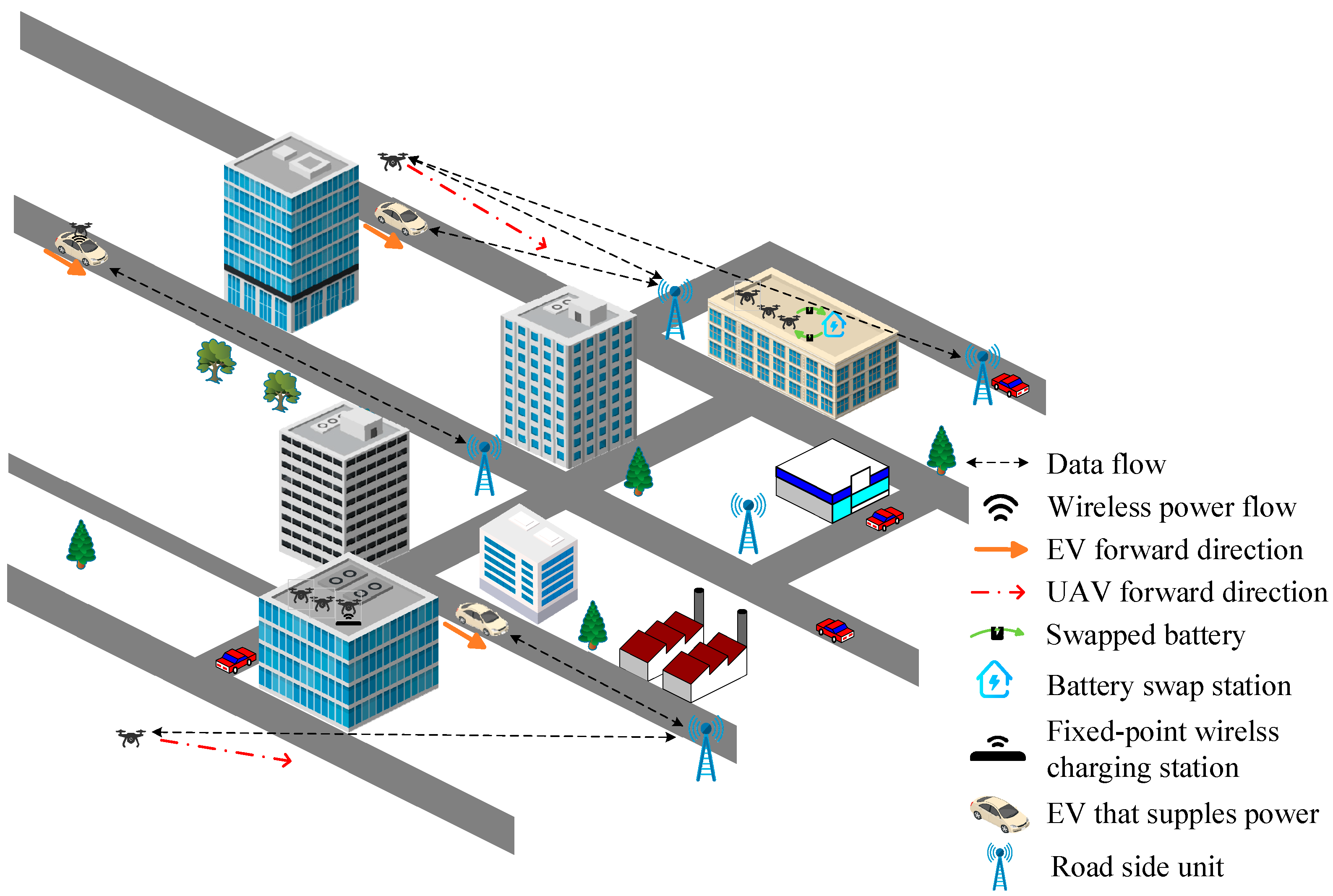
Two types of flight missions are performed by a UAV in this study, including a regular mission such as ordinary logistics, and an emergency mission, such as medical supplies or fresh food delivery services. A UAV operator always puts the charging cost as the first consideration in the determination of flight paths of UAVs on regular missions, whereas the operator of a UAV on emergency mission is willing to charge at a higher cost to avoid spending too much time waiting for charging because this type of UAV has a time constraint on arrival at its destination.
As shown in Figure 1, this work adopts two traditional charging methods from the literature, i.e., fixed-point wireless charging stations and battery exchange facilities built on the roofs of two buildings recharge the battery power of the UAVs on regular missions. This type of UAV requires longer waiting times for charging in exchange for lower charging fees during peak periods. On the other hand, for the UAVs performing emergency missions, the EV-to-UAV charging method, as shown in the bottom right of Figure 1, is selected as the preferred charging option in order that the UAVs can complete their flight mission in time. In this study, roadside units (RSUs) as shown in Figure 1 are responsible for coordinating battery charging between a moving EV and a UAV requesting power. If an EV can offer power to a UAV with a recharging need, the EV will inform the RSUs located on the way to its destination of the available electricity when the EV traverses the road sections that the corresponding RUSs govern. Meanwhile, a UAV that requires power will contact the RSUs close to its current flight route to check if any moving EV is available to charge the battery of the UAV.
Based on the above-mentioned problem scenarios, the modelling and solution framework of this study is composed of three components as shown in Figure 2. Before departure of an EV, the EV driver uses the module installed on the on-board unit, as shown in the bottom left of Figure 2, to calculate the shortest route to the destination and notify the RSU of the estimated arrival time of the EV on each section of the route. Each EV checks the state of charge (SoC) of its battery when planning the route. If an EV is found to be running out of battery power before reaching its destination and the EV driver does not have a time pressure to reach the destination, this work will recommend that the EV be charged with a less expensive charging option, such as driving to a plug-in charging station or a battery exchange facility on the way to the destination. Conversely, if the EV needs to get to its destination as quickly as possible, a wireless road charging panel is the preferred charging option.
The module given in the bottom right of Figure 2 is used to determine the fight path for a UAV before departure. If the UAV is estimated to deplete its battery electricity before completion of its mission, it can choose a fixed-point wireless charging station, a battery exchange facility, or to take a side trip by landing on the roof the EV while in motion, depending on the characteristics of the mission and the operation cost. Notably, EVs equipped with wireless discharging devices can inform the RSU of the road segment of the route of the available power and charging price, and wirelessly offer power to the UAVs that need to be charged urgently, during its flight mission if necessary.
Upon receipt of an emergency charging request from a UAV, the RSUs of the road sections nearby the flight path of the UAV activate the charging and discharging management module at the top of Figure 2, search for an EV with a similar arrival time that can provide excess power according to the arrival time of the UAV in need of power, and notify the UAV of the matching results. The UAV then selects the EV(s) offering the lowest charging cost and informs the RSU(s) on the road section(s) of the UAV’s decision. As the arrival times of the EVs at each road section may vary from the original estimate, the UAV that chooses the in-motion EV charging option will only be charged once both the EV(s) and UAV have arrived at the designated road section(s). The work also assumes that the power management organization or electricity operators will provide incentives to EV owners and UAV operators, such as offering subsidies to EV owners and UAV operators for the installation of wireless charging panels, so as to attract more EV owners to provide electricity to UAVs with emergency needs, thereby preventing the imbalance between electricity supply and demand and the congestion at charging stations or battery exchange stations during peak hours.

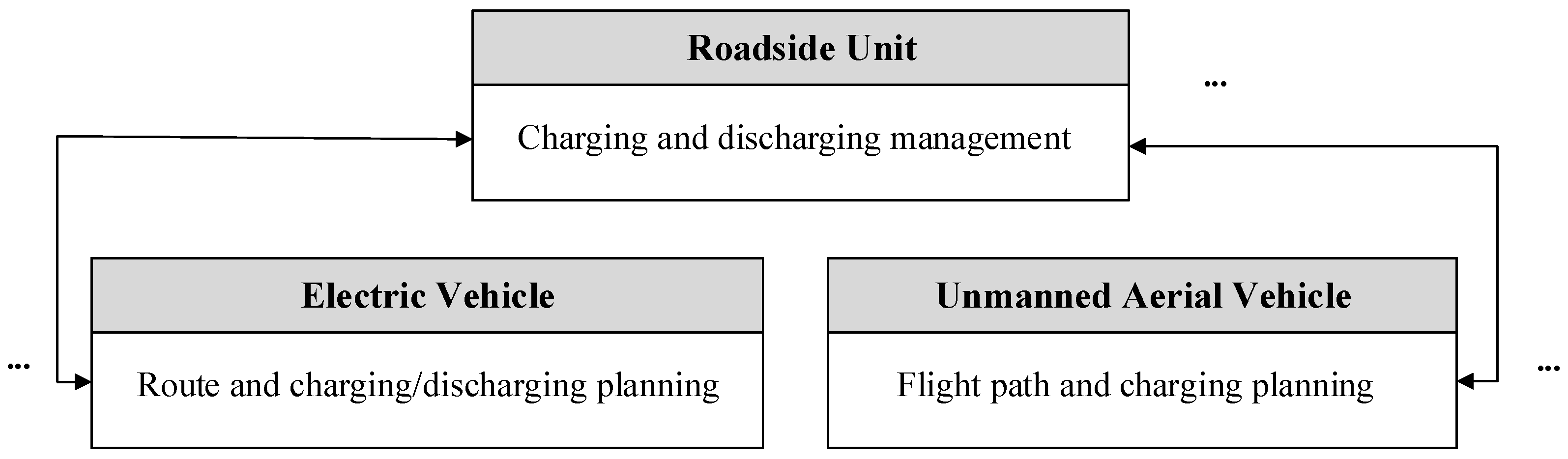
2.1. Route and Charging and Discharging Planning for an EV

This module is used to determine the route and charging path of an EV before its departure based on the existing road traffic information in the EV database as the input data. Here, we assume an EV driver will set up a route at the start of the journey and informs the RSU of the estimated arrival time of the EV at each section of the route. The EV will also check the battery status of the EV when planning the route. If it is found that the EV will run out of battery power before reaching its destination, the EV users can choose the appropriate charging option based on their personal needs or cost considerations.
This module offers three charging options for EV users, including plug-in charging, battery exchange, and dynamic wireless charging on the road. Plug-in charging stations are relatively inexpensive because they take longer to charge, so an EV user who is unable to charge their EV due to the limited number of plug-in charging docks at their home or office can choose the nearest plug-in charging station that charges less. Battery exchange stations take less time to exchange batteries, but can lengthen the wait time for battery replacement due to the influx of too many vehicles. The wireless road charging method eliminates the waiting and charging time because it can charge while driving. However, the charging cost is the highest. Only when there is an urgent need for charging will EV users choose the most expensive wireless road charging option.
By adopting the existing road traffic information in the EV database as the input data, this module first determines the cost of each route by the time the EV is scheduled to pass through each road segment, and up to K candidate routes are generated using the Yen shortest route algorithm [29] and ranked by distance travelled. A candidate route can be denoted as:
C R l σ = c 0 l , c 1 l , , c i l , , c h l σ l ,
where l is the index of the candidate route, c 0 l , c i l , and c h l σ l represent the starting location of candidate route l, the ith intersection on the route, and the destination of EV σ , respectively. Notably, the sorted candidate route list is generated by satisfying the following constraint:
1 i < h l σ s l c i l , c i + 1 l σ 1 i < h l + 1 σ s l c i l + 1 , c i + 1 l + 1 σ ,   1 l < K
where s l c i l , c i + 1 l σ stands for the length of the road section between intersections c i l and c i + 1 l on σ ’s route.
Starting with σ ’s first candidate route in the sorted list, examine if there is a route that satisfies the following constraint of σ ’s battery electricity:
S O C c 0 l σ a p σ · s l c i l , c i + 1 l σ S O C ¯ σ , 0 i < h l σ
where S O C c 0 l σ and S O C ¯ σ represent the battery storage capacity of EV σ at the time of its departure and the lower limit of its battery storage capacity, respectively. a p σ represents the battery consumption per kilometer of σ , and s l c i l , c i + 1 l σ is the total distance of the lth candidate route of σ .
If there is a route among the K candidate ones that satisfies the constraint as given in Equation (3), the route with the lowest index value is selected as the EV’s route, and the following equation is also calculated to compute the electricity that the EV σ can offer for a UAV in need of power, and the module is terminated.
E R E ¯ c i l , c i + 1 l σ = η σ · S O C c i + 1 l σ S O C c i l σ ,   0 η σ 1 ,   0 i h l σ ,   1 l K
where E R E ¯ c i l , c i + 1 l σ stands for the remaining power of σ before leaving the roadway connecting c i l and c i + 1 l . η σ denotes the charging efficiency of σ ’s battery.
Otherwise, the list of candidate routes according to the EV user’s preference. This module needs to compute the time for σ to reach each intersection on its way to the destination as follows:
r t c 1 l σ = r t c 0 l σ + S D c 0 l , c 1 l σ r t c 0 l σ , 1 l K
r t c i + 1 l σ = r t c i l σ + I D c i l , c i + 1 l σ r t c i l σ + S D c i l , c i + 1 l σ r t c i l σ + ϕ c i l σ · P W T c i l σ r t c i l σ + c t c i l σ + ψ c i l σ · B W T c i l σ r t c i l σ + B S T c i l σ r t c i l σ ,   1 i < h l σ   , 1 l K
where r t c i l σ denotes the time that σ reaches the road intersection indexed by c i l on the lth candidate route. S D c i l , c i + 1 l σ r t c i l σ represents the time spent by σ that travels the roadway connecting c i l and c i + 1 l after the EV passes c i l , while I D c i l , c i + 1 l σ r t c i l σ denotes the time spent at road intersection c i l owing to traffic light control. P W T c i l σ r t c i l σ stands for the waiting time for the battery of σ before charging at the plug-in charging station c i l , while B W T c i l σ r t c i l σ and B S T c i l σ r t c i l σ represent the waiting time and battery replacement time spent at the battery exchange service facility c i l , respectively. Given the effectiveness of machine learning in predicting road travel times, this work uses support vector regression (SVR) [30] techniques to calculate the five above parameters based on the history data. The binary flags ϕ c i l σ and ψ c i l σ are used to indicate whether σ is charged using a plug-in charging station or battery exchange service facility with index c i l . In addition, all plug-in charging stations and battery exchange service facilities are treated as road crossings to simplify the calculation.
Based on the arrival time at each road intersection on the way to the destination, σ ’s battery storage capacity after it reaches each road intersection ahead can be determined by satisfying the following constraints:
S O C c i + 1 l σ = S O C c i l σ + η σ · ϕ c i l σ · p c p c i l σ · c t c i l σ + η σ · θ c i l , c i + 1 l σ · w c p c i l , c i + 1 l σ · S D c i l , c i + 1 l σ r t c i l σ + ψ c i l σ · S O C ¯ σ S O C c i l σ a p σ · s l c i l , c i + 1 l σ ,   0 i < h l σ , 1 l K
0 c t c i l σ c t ¯ c i l σ , if   ϕ c i l σ = 1
S O C ¯ σ S O C c i l σ S O C ¯ σ , 0 i h l σ ,   1 l K
1 i < h l σ ϕ c i l σ + θ c i l , c i + 1 l σ + ψ c i l σ 1 ,   if   S O C c 0 l σ a p σ · 0 i < h l σ s l c i l , c i + 1 l σ < S O C ¯ σ ,   1 l K
where p c p c i l σ stands for the charging power of a plug-in charging station, while w c p c i l , c i + 1 l σ is the charging power of the wireless charging pad paved on the road section connecting c i l and c i + 1 l . The binary flag θ c i l , c i + 1 l σ is used to indicate whether σ is charged using a road wireless charging pad between c i l and c i + 1 l . S O C ¯ σ denotes the upper limit of σ ’s battery storage capacity. c t c i l σ and c t ¯ c i l σ denote the actual and allowed upper limit of charging time for the battery of σ at the plug-in charging station c i l , respectively.
The route and charging path of σ can be the computed subject to the above-mentioned constraints:
arg min l { ω 1 σ · r t c h l σ l σ r t c 0 l σ + ω 2 σ · 0 i < h l σ s l c i l , c i + 1 l σ + ω 3 σ · [ 1 i < h l σ ϕ c i l σ · R P c i l σ r t c i l σ · p c p c i l σ · c t c i l σ + 1 i < h l σ θ c i l , c i + 1 l σ · W R P c i l , c i + 1 l σ r t c i l σ · w c p c i l , c i + 1 l σ · W S D c i l , c i + 1 l σ r t c i l σ + 1 i < h l σ ψ c i l σ · R P c i l σ r t c i l σ · S O C ¯ σ S O C c i l σ ] } ,   1 l K
subject to Equations (2)–(10).
In the optimization formulation, as given in Equation (11), l represents the decision variables in the arg min(·) operation. The three parameters from left to right in the calculation represent the travel time from the departure point to the destination, the total distance traveled to the destination, and the charging cost of an EV σ battery, respectively. Notably, EV users can set the three weights, ω 1 σ , ω 2 σ , and ω 3 σ , according to their needs. If the EV battery has enough power to reach the destination, ω 3 σ will be set to zero. R P c i l σ r t c i l σ stands for the real-time charging price of the plug-in charging or battery exchange service for EV σ at road intersection c i l at time r t c i l σ . W R P c i l , c i + 1 l σ r t c i l σ denotes the real-time charging price of the road wireless charging panel for EV σ traveling through the road section connecting c i l and c i + 1 l at time r t c i l σ , while W S D c i l , c i + 1 l σ r t c i l σ represents the charging time of the wireless charging on the road section connecting c i l and c i + 1 l . Again, SVR is adopted to estimate the above-mentioned three parameters based on the historical data.
After the route for EV σ is determined by Equation (11), this module checks if σ does not need to be charged before arriving at its destination and is willing to offer the excess battery electricity E R E ¯ c i l , c i + 1 l σ to a UAV in need of power that flies near the road section between the c i l and c i + 1 l at a similar time. If so, the RSUs of the road section between the c i l and c i + 1 l will be notified of the time of arrival at the section, the excess battery electricity of the EV, the charging power, and the charging price.
The module then performs background execution mode. The arrival time at the roadway is recalculated at fixed time intervals. If the estimated time of arrival at the roadway is different from the original estimate due to traffic congestion during peak hours or a schedule change of the EV user, the RSU in charge of the roadway will be notified of the updated arrival time.
The step-by-step description of the Algorithm 1 is given below:
Algorithm 1 Route and Charging and Discharging Planning for an EV
Step 1: Before the departure of the EV, apply Yen Shortest Path algorithm [29] to select at most K shortest routes of the EV.
Step 2: Sort the candidate route list in ascending order of driving distance.
Step 3: Select the candidate route with the smallest index in the list that satisfies the constraint, as specified in Equation (3).
Step 4: If a route is found at Step 3, compute the electricity that the EV can offer for a UAV in need of power on the way to the EV’s destination as given in Equation (4), and then proceed to Step 7.
Otherwise, proceed to the next step.
Step 5: Use Equation (11) to compute the suitable route for the EV by satisfying the constraints specified from Equations (2)–(10).
Step 6: Notify the RSUs located on the way of the EV’s destination, including the excess battery electricity, that the EV can offer a UAV in need of power.
Step 7: The time that the moving EV reaches each intersection ahead is recalculated at fixed time intervals.
Step 8: If the updated arrival time is different from the original estimate, all RSUs in charge of the roadways will be timely notified. Proceed to Step 7.

2.2. Flight Path and Charging Planning for a UAV

This module first adopts the UAV path selection algorithm proposed in [31] to select multiple candidate flight routes for UAVs, assuming real-time positions and velocities of obstacle aircraft are available for the application of the algorithm given in [31]. A flight route and charging planning integration solution that fits each individual UAV is then selected according to the charging requirements and cost considerations of the UAV operator. The UAV path selection algorithm in [31] is chosen in this work because this algorithm can avoid fixed and moving obstacles when calculating flight paths.
A list of up to K flight paths for a UAV is first generated by using the algorithm in [31] and the list is sorted in ascending order by flight distance. A candidate flight path can be denoted as:
F P l β = n 0 l , n 1 l , , n i l , , n h l β l ,
where l is the index of the candidate flight path, n 0 l , n i l , and n h l β l represent the starting location of candidate flight path l, the ith intersection on the flight path, and the destination of UAV β , respectively.
Then, this module examines whether there is a flight path that satisfies the following constraint:
S O C n 0 l β a p β · s l n i l , n i + 1 l β S O C ¯ β , 0 i < h l β
where β is the index of the UAV, n 0 l , n i l , and n h l β l represent the starting position of the candidate flight route with index value l, the ith waypoint on candidate route l, and the destination, respectively. S O C n 0 l β and S O C ¯ β denote the battery storage capacity of UAV β at the time of departure and the lower limit of the battery storage capacity, respectively. a p β stands for the battery power consumption per kilometer of UAV β . s l n i l , n i + 1 l β represents the length of the UAV β flight route between the waypoints n i l and n i + 1 l , and s l n i l , n i + 1 l β is the total distance of candidate route l.
If any flight path(s) that satisfy the constraint as given in Equation (13) among the K candidate ones are available, the flight path with the lowest index value is selected as the flight path of UAV β , and the module is terminated. Otherwise, this module employs the algorithm given in [31] to select the flight path from the origin to a designated charging point and then from the charging point to the destination by satisfying the constraints given below.
Assuming a candidate flight path generated by the algorithm given in [31], D R l β , is expressed as follows:
D R l β = n ^ 0 l , n ^ 1 l , , n ^ i l , , n ^ h ^ l β l ,   1 l K
n ^ 0 l = n 0 l ,   n ^ h ^ l β l = n h l β l ,   1 l K
where l is the index of UAV β ’s candidate flight path, n ^ 0 l , n ^ i l , and n ^ h ^ l β l represent the starting location of candidate flight path l, the ith waypoint on the flight path, and the destination of β , respectively. Equation (15) is used to ensure the departure and the destination of the updated flight route are identical to the original ones.
This module computes the time for UAV β to reach the ith waypoint on its way to the destination if the EV-to-UAV charging option is chosen:
r t n ^ i l β = max r t n ^ i l β , κ n ^ i l , n ^ i + 1 l β · B Q R n ^ i l , n ^ i + 1 l c u r A T ,   0 i < h ^ l β ,   1 l K
where r t n ^ i l β denotes the time that UAV β reaches the waypoint indexed by n ^ i l on the lth candidate flight path. The binary flag κ n ^ l , i β , n ^ l , i + 1 β β is used to indicate whether an EV traveling between n ^ l , i β and n ^ l , i + 1 β will offer β the electricity. B Q R n ^ i l , n ^ i + 1 l c u r represents the pointer to the EV’s record that can offer power to β at the road section connecting n ^ i l and n ^ i + 1 l , and the attributes AT of B Q R n ^ i l , n ^ i + 1 l c u r stand for the time that the EV arriving at n ^ i l . Accordingly, Equation (16) is used to express the possible delay time at the meeting point of UAV β and the EV supplying power. Notably, B Q R n ^ i l , n ^ i + 1 l c u r can be determined by:
B Q R n ^ i l , n ^ i + 1 l c u r = B Q n ^ i l , n ^ i + 1 l τ , if     κ n ^ i l , n ^ i + 1 l β = 1   and   r t c u r + τ 1 · Δ r t n ^ i l β < r t c u r + τ · Δ , τ 1
B Q R n ^ i l , n ^ i + 1 l c u r = B Q R n ^ i l , n ^ i + 1 l c u r N E X T , if   κ n ^ i l , n ^ i + 1 l β = 1   and   B Q R n ^ i l , n ^ i + 1 l c u r E R E < B Q R n ^ i l , n ^ i + 1 l c u r E C P · E S D n ^ i l , n ^ i + 1 l r t n ^ i l β
where B Q n ^ i l , n ^ i + 1 l τ denotes the pointer to the first record of the EV charging supply list that is kept at the RSU governing the road section connecting n ^ i l and n ^ i + 1 l . r t n ^ i l β is the current time, and τ denotes the index for the time interval that β arrives at n ^ i l . Notably, the EV charging supply list is sorted in ascending order by the amount of electricity that can be supplied by the EVs on the list, and Equation (18) is used to locate the EV that matches the electricity required by β as far as possible.
The (i+1)th waypoint on the way to the UAV’s destination can be determined by incorporating the possible charging delay as follows:
r t n ^ i + 1 l β = r t n ^ i l β + κ n ^ i l , n ^ i + 1 l β · E S D n ^ i l , n ^ i + 1 l r t n ^ i l β + l t β + ϕ n ^ i l β · P W T n ^ i l β r t n ^ i l β + c t n ^ i l β + l t β + ψ n ^ i l β · B W T n ^ i l β r t n ^ i l β + B S T n ^ i l β r t n ^ i l β + l t β + 1 κ n ^ i l , n ^ i + 1 l β · 1 ϕ n ^ i l β · 1 ψ n ^ i l β · s l n ^ i l , n ^ i + 1 l β s p d n ^ i l β ,   0 i < h ^ l β ,   1 l K
s l n ^ i l , n ^ i + 1 l β = 0 ,   0 i < h ^ l β ,   1 l K ,   if   κ n ^ i l , n ^ i + 1 l β = 1
where the binary flags ϕ n ^ l , i β β and ψ n ^ l , i β β are used to mark whether β will recharge at a fixed-point wireless charging station or battery swap facility located at n ^ i l . E S D n ^ i l , n ^ i + 1 l r t n ^ i l β denotes the charging time of UAV β if the EV-to-UAV charging option is chosen, P W T n ^ i l β r t n ^ i l β stands for the waiting time at the wireless charging station, B W T n ^ i l β r t n ^ i l β and B S T n ^ i l β r t n ^ i l β represent the waiting time and battery swapping time at the battery exchange service located at n ^ i l , respectively. l t β stands for the takeoff and landing time at the charging site, while c t n ^ i l β denotes the actual charging time of the battery at the fixed-point wireless charging station. s p d n ^ i l β is the flight speed of UAV β. Again, SVR is used to calculate the P W T n ^ i l β · , B W T n ^ i l β · , and B S T n ^ i l β · based on the historical data. In addition, Equation (20) is used to reflect the fact that β moves with the EV while β gets charged from the EV.
The battery storage capacity of β after reaching each waypoint ahead can be determined by satisfying the following constraints:
S O C n ^ i + 1 l β = S O C n ^ i l β + η β · ϕ n ^ i l β · p c p n ^ i l β · c t n ^ i l β + ψ n ^ i l β · S O C ¯ β S O C n ^ i l β + η β · κ n ^ i l , n ^ i + 1 l β · R R E n ^ i l , n ^ i + 1 l β a p β · s l n ^ i l , n ^ i + 1 l β ,   0 i < h ^ l β ,   1 l K
0 c t n ^ i l β c t ¯ n ^ i l β , if   ϕ n ^ i l β = 1
S O C ¯ β S O C n ^ i l β S O C ¯ β ,   0 η β 1 ,   0 i h ^ l β ,   1 l K
R R E n ^ i l , n ^ i + 1 l β = B Q R n ^ i l , n ^ i + 1 l c u r E C P · E S D n ^ i l , n ^ i + 1 l r t n ^ i l β B Q R n ^ i l , n ^ i + 1 l c u r E R E , if   κ n ^ i l , n ^ i + 1 l β = 1
E S D n ^ i l , n ^ i + 1 l r t n ^ i l β B Q R n ^ i l , n ^ i + 1 l c u r S D , if   κ n ^ i l , n ^ i + 1 l β = 1
1 i < h ^ l β ϕ n ^ i l β + κ n ^ i l , n ^ i + 1 l β + ψ n ^ i l β 1 ,   if   S O C n ^ 0 l β a p β · 0 i < h ^ l β s l n ^ i l , n ^ i + 1 l β < S O C ¯ β , 1 l K
where p c p n ^ l , i β β , c t n ^ l , i β β , and c t ¯ n ^ l , i β β stand for the charging power, the actual charging time, and maximum charging time of the UAV’s battery at the fixed-point wireless charging station located at n ^ l , i β , respectively. S O C ¯ β and S O C ¯ β represent the upper and lower limits of the EV’s battery capacity, respectively, and S O C n ^ i l β denotes the remaining battery capacity when β reaches n ^ l , i β . R R E n ^ i l , n ^ i + 1 l β denotes the electricity that the EV offers β at the road section connecting n ^ i l and n ^ i + 1 l . a p β stands for the battery power consumption of the UAV per kilometer, and η β denotes the charging efficiency of its battery. The attributes ERE, ECP, SD and ERP stand for the maximum amount of power that can be provided by the EV, charging power, passing time of the road section, and electricity price of B Q R n ^ i l , n ^ i + 1 l c u r , respectively. Notably, Equation (24) is used to ensure that the electricity β gets charged from the EV should not exceed the maximum amount of electricity the EV can offer, Equation (25) is used to set the charging time of β less than or equal to the length of the road section connecting n ^ i l and n ^ i + 1 l , and Equation (26) is used to ensure one of the three charging options should be chosen if the battery electricity of β is not enough to arrive at the destination.
The flight path of β can be updated subject to the above-mentioned constraints:
arg min l { ω 1 β · r t n ^ h ^ l β l β r t n ^ 0 l β + ω 2 β · 0 i < h ^ l β s l n ^ i l , n ^ i + 1 l β + ω 3 β · [ 1 i < h ^ l β κ n ^ i l , n ^ i + 1 l β · B Q R c u r E R P · B Q R c u r E C P · E S D n ^ i l , n ^ i + 1 l r t n ^ i l β + 1 i < h ^ l β ϕ n ^ i l β · R P n ^ i l β r t n ^ i l β · p c p n ^ i l β · c t n ^ i l β + 1 i < h ^ l β ψ n ^ i l β · R P n ^ i l β r t n ^ i l β · S O C ¯ β S O C n ^ i l β ] } ,   1 l K
subject to Equations (14)–(26).
In the optimization formulation, as given in Equation (27), l represents the decision variables in the arg min(·) operation. The three parameters from left to right in the calculation represent the flight time, flight distance, and the battery charge cost of UAV β from the origin to the destination, respectively. The UAV operator can set the weight values of ω 1 β , ω 2 β , and ω 3 β according to the specific needs of the UAV’s mission. If UAV β has enough power to reach the destination, it does not need to charge its battery on the way to its destination and ω 3 β will be set to zero accordingly. R P n ^ i l β r t n ^ i l β denotes the real-time charging power of a fixed-point wireless charging station or battery exchange service located at n ^ i l at time r t n ^ i l β .
The step-by-step description of the Algorithm 2 is given below:
Algorithm 2 Flight Path and Charging Planning for a UAV
Step 1: Before the take-off of the UAV, apply the UAV path selection algorithm proposed in [31] to select up to K candidate flight paths for the UAV in ascending order of the UAV’s flight distance.
Step 2: Check if any flight paths in the candidate list satisfy the constraint, as specified in Equation (13).
Step 3: If any flight paths are found at Step 2, select the candidate flight path with the smallest index in the list as the flight path of the UAV, and terminate this module.
Otherwise, proceed to the next step.
Step 4: Use Equation (27) to compute a suitable route for the UAV by satisfying the constraints specified from Equations (14)–(26).

2.3. Charging and Discharging Management at The Roadside Unit

After an EV determines the route to its destination before departure, it will notify the RSUs at the sections on the way to the destination of the amount of power that can be supplied by the EV’s battery based on the times of the EV reaching the corresponding sections. The RSUs that receive the notifications will then create a list of power supplies in ascending order of the selling price of the power. Each record in the list contains five attributes: the EV ID, the time of arrival at the road section, the amount of electricity available, the charging power, the price of the electricity, and the pointer to the next record. Upon receipt of a request for electricity supply from a UAV, the RSU will select the EV with the lowest price from the electricity supply list and notify the UAV and the EV that supplies the electricity. As the actual arrival times of EVs at the road sections may vary from the predicted time due to congestion during peak hours or an unexpected change of schedule, EVs or UAVs arriving earlier will wait for those arriving later at the designated meet point. The RSUs in charge of the road sections also update the electricity supply information of the corresponding road sections immediately by moving the EVs from the original scheduled time slots to the post-change time slots according to the notification of the updated arrival times of the EVs.
This module inserts and records a new electricity supply record whenever the RSU is notified by an EV providing power that will travel through the road section that the RSU governs as follows:
n e w B Q R σ
B Q R σ I D = σ
B Q R σ A T = r t p σ
B Q R σ E R E = E R E ¯ p , q σ
B Q R σ E C P = e c p p , q σ
B Q R σ E R P = E R P σ r t p σ
B Q R σ S D = S D p , q σ r t p σ
where p denotes the meet point (intersection) at which EV σ arrives, r t p σ , E R E ¯ p , q σ , e c p p , q σ , and E R P σ r t p σ represent the time at which EV σ arrives at the intersection, the amount of electricity and charging power that can be provided at the road section connecting p and q, and the price of electricity, respectively. The six attributes of B Q R σ , including I D , A T , E R E , ECP, SD and ERP represent the ID of the EV, arrival time of the EV at p, the power available, the charging power and time spent on the road section, and the electricity price.
This module then adds the record of EV σ into the list by searching for the record right below the price of electricity claimed by EV σ and add the new record thereafter:
B Q R c u r = B Q p , q τ ,   r t p σ r t c u r + τ 1 · Δ ,   r t c u r + τ · Δ ,   τ 1
B Q R c u r = B Q R c u r N E X T ,   i f   B Q R c u r N E X T E R P < B Q R σ E R P
B Q R σ N E X T = B Q R c u r N E X T
B Q R c u r N E X T = B Q R σ
where B Q p , q τ represents the pointer to the first record of the power supply list on the road section connecting p and q in period τ, the indicator of the next record in the NEXT attribute, and r t c u r is the current time.
Next, the module enters background execution mode. If a notification is received for an EV that does not arrive on time at the designated road section, it will be removed from the corresponding power supply list and the EV arriving at a later time will be added to the power supply list during the updated arrival time period:
B Q R c u r = B Q p , q τ ,   o r t p σ r t c u r + τ 1 · Δ ,   r t c u r + τ · Δ ,   τ 1
B Q R c u r = B Q R c u r N E X T ,   i f   B Q R c u r N E X T I D σ
B Q R σ = B Q R c u r N E X T
B Q R c u r N E X T = B Q R c u r N E X T N E X T
B Q R c u r = B Q p , q τ ,   n r t p σ r t c u r + τ 1 · Δ ,   r t c u r + τ · Δ ,   τ 1
B Q R c u r = B Q R c u r N E X T ,   i f   B Q R c u r N E X T E R P < E R P σ n r t p σ
B Q R σ N E X T = B Q R c u r N E X T
B Q R c u r N E X T = B Q R σ
where o r t p σ and n r t p σ are the original estimated arrival time and the updated arrival time of EV σ at the meeting point indexed by p, respectively. B Q R σ and E R P σ n r t p σ denote the pointer to the record of EV σ and its electricity price at the arrival time.
This module then continues with the background execution mode. If a new power supply notification of an EV is received, start from Equation (28) to execute the next iteration of this module.
If a request of electricity supply for a UAV is received, the EV that can meet the electricity demand with the lowest electricity price is selected from the power supply list recorded in the RSU. The supplying EV will also inform all RSUs on the rest of the road sections it will travel through to update the amount on the electricity supply recorded in the above-mentioned RSUs. The electricity supply information updated in each of these RSUs is shown as follows:
B Q R c u r = B Q p , q τ ,   r t c u r + τ 1 · Δ r t p σ < r t c u r + τ · Δ ,   τ 1
B Q R c u r = B Q R c u r N E X T ,   i f   B Q R c u r . I D σ
B Q R σ E R E = B Q R σ E R E R R E p , q γ
where R R E p , q γ is the battery power required by UAV γ on the road section between p and q. This module then continues with the background execution mode after the amount of electricity that can offered by the EV is updated.
The step-by-step description of the Algorithm 3 is given below:
Algorithm 3 Charging and Discharging Management at The Roadside Unit
Step 1: Use Equations (28)–(34) to insert a new electricity supply record after the RSU is notified by an EV providing power that it will travel through the road section that the RSU governs.
Step 2: Use Equations (35)–(38) to add the record of the EV into the list by searching for the record right below the price of electricity claimed by EV and add the new record thereafter.
Step 3: This module enters background execution mode.
Step 4: If a notification is received for an EV that does not arrive on time at the designated road section, use Equations (39)–(46) to move the EV’s record to the list at the corrected arrival time period. Proceed to Step 3.
Step 5: If a new power supply notification of an EV is received, start from Equation (28) to execute the next iteration of this module.
Step 6: If a request of electricity supply for a UAV is received, the EV that meets the electricity demand with the lowest electricity price is selected from the power supply list recorded at the RSU.
Use Equations (47)–(49) to update the EV’s electricity supply record. Proceed to Step 3.

3. Simulation Results

This study ran a series of simulations to examine the effectiveness of the proposed algorithm. The simulations were performed on a PC with Intel Core i7 at 2.9 GHz CPU and 64GB RAM. The historical traffic data were obtained from a web site of traffic volume counts for New York City [32]. Fifty wireless charging stations for UAVs and 40 battery exchange charging stations for UAVs were set up in the simulation area for charging UAVs. In addition, 47 large road intersections were selected for EV-to-UAV charging, including a total of 384 EV routes used for UAV charging. The total number of the missions was 7062, including 5030 regular cargo delivery orders and 2032 emergency missions. When the simulation was started, the time, distance, start time, and final completion time of each mission were recorded. The time of charging request, the time of starting charging, the time of arriving at the charging point, the time of finishing charging, and the amount of electricity obtained after charging were also recorded when a UAV needed to charge while performing its mission.
Figure 3 shows the number of EVs driving on the roads within a day in our simulation. A surge of traffic volume can be observed during the morning and evening peak hours.
As shown in Figure 4 and Figure 5, the missions were divided into regular orders and emergency missions with a deadline of arrival for goods deliveries. A small number of orders for goods was observed between the midnight and morning peak hours. From around 08:00 onwards, the frequency of consumer orders gradually rose until the lunch break ends. Evening was the peak period when consumers placed the highest frequency of delivery goods orders. After the evening peak period, the number of orders decreased sharply before midnight.
Figure 6 shows the number of charging requests for UAVs within a day. It can be seen that the counts of charging requests were directly proportional to the number of missions. Accordingly, the charging requests increased significantly during morning and evening peak hours because the UAVs consumed a lot of electricity while continuing to deliver goods during busy periods.
As there is no pressure on the delivery time for regular delivery orders carried by the UAVs, the preferred charging options for this type of mission will be a fixed-point wireless charging station or battery exchange station due to the operating cost considerations as shown in Figure 7. The number of charging requests surged during morning and evening peak periods as expected.
Since emergency orders need to be delivered to the destination before the deadline expected by the consumers, the primary charging option is EV-to-UAV charging for this type of delivery missions. As observed from Figure 8, it is clear that the use of EV-to-UAV charging for emergency orders was much higher than the use of other charging options, including wireless charging stations and battery swap stations.
When a UAV adopts the EV-to-UAV charging option for an emergency mission, the UAV keeps parking on the top of the moving EV during the charging period. Accordingly, the UAV follows the movement of the EV at a slower speed but still keeps moving forward, although the path of the EV does not exactly match the flight path of the UAV. Figure 9 shows the extra time spent by the UAVs if their batteries need to get charged during flight missions. The charging times for the UAVs were directly proportional to the number of charging requests as expected. However, compared with the charging time for regular missions, the extra time spent on charging is much lower for emergency missions during peak periods because most of the charging took use of the EV-to-UAV charging option. The time spent on charging for a UAV was lower even if it might deviate slightly from the original flight path. That is, it is much better than queuing up at the traditional fixed-point wireless charging stations and battery exchange stations during peak hours.
Figure 10 shows the comparison of charging/discharging profiles for the EV battery electricity. Notably, the positive values shown in the curves mean that the aggregation of battery storage systems are in discharging states, and vice versa. It can be revealed that the EV batteries were at the discharging state to offer the power to the requesting UAVs during morning and evening peak hours. On the contrary, EVs got charged after the EVs arrived at homes or workplace to refill the power with cheaper electricity. Accordingly, the congestion for UAVs waiting for charging that occurred at the traditional fixed-point wireless charging stations and battery exchange stations was alleviated and the power load was also mitigated via EV-to-UAV charging during peak periods.

4. Conclusions

Although several studies in the recent literature have conducted approaches to provide power to UAVs through wireless charging technology, the presented charging schemes in the literature have never addressed the issue of charging congestion at the charging facilities during peak periods. If a UAV is used to transport goods for urgent needs, it might be unable to arrive at the destination in the time requested by the customer. In addition, different charging options should be offered for each individual drone depending on its mission characteristics and needs. In view of this, this work proposed a joint routing path and charging plan to meet the task characteristics and charging needs of various types of UAVs. The experimental results demonstrated that the EV-assisted UAV charging mechanism proposed in this study can effectively reduce the time spent on charging when the UAVs perform emergency missions, and enable the UAV to deliver urgent goods to the designated destination on schedule even when the traditional fixed-point wireless charging stations and battery exchange stations are congested. Therefore, the proposed algorithm can not only establish a suitable flight path and charging planning for UAVs loaded with emergency orders, but also mitigate the power load on the grid during peak hours via the assistance of an EV-to-UAV charging mechanism. As a result, a multi-win situation for EV owners, UAV operators, UAV customers, and power companies is effectively achieved. However, as seen from the recent literature 9,23,24, new advanced charging technologies for UAVs have been proposed by researchers. Thus, our future work will incorporate these evolving charging technologies into our integrated charging mechanism to meet the task characteristics and charging needs of various types of UAVs.

Author Contributions

Conceptualization, C.-J.H.; methodology, C.-J.H.; software, K.-W.H.; writing, K.-W.H.; reviewing and editing, H.-W.C. All authors have read and agreed to the published version of the manuscript.

Funding

The authors would like to thank the National Science and Technology Council, Taiwan, for the financially supporting this research under Contract Number MOST 111-2221-E-259-003.

Data Availability Statement

Not applicable.

Conflicts of Interest

The authors declare no conflict of interest.

References

  1. Zou, W.; Sun, Y.; Gao, D.C.; Zhang, X.; Liu, J. A review on integration of surging plug-in electric vehicles charging in energy-flexible buildings: Impacts analysis, collaborative management technologies, and future perspective. Appl. Energy 2023, 331, 120393. [Google Scholar] [CrossRef]
  2. Ullah, Z.; Wang, S.; Wu, G.; Hasanien, H.M.; Rehman, A.U.; Turky, R.A.; Elkadeem, M.R. Optimal scheduling and techno-economic analysis of electric vehicles by implementing solar-based grid-tied charging station. Energy 2022, 267, 126560. [Google Scholar] [CrossRef]
  3. Haider, S.; Walewski, J.; Schegner, P. Investigating peer-to-peer power transactions for reducing EV induced network congestion. Energy 2022, 254, 124317. [Google Scholar] [CrossRef]
  4. Qiu, J.; Du, L. Optimal dispatching of electric vehicles for providing charging on-demand service leveraging charging-on-the-move technology. Transp. Res. Part C Emerg. Technol. 2023, 146, 103968. [Google Scholar] [CrossRef]
  5. Shafiqurrahman, A.; Umesh, B.S.; Al Sayari, N.; Khadkikar, V. Electric Vehicle-To-Vehicle Energy Transfer Using On-board Converters. IEEE Trans. Transp. Electrif. 2022, 9, 1263–1272. [Google Scholar] [CrossRef]
  6. Shurrab, M.; Singh, S.; Otrok, H.; Mizouni, R.; Khadkikar, V.; Zeineldin, H. A Stable Matching Game for V2V Energy Sharing-A User Satisfaction Framework. IEEE Trans. Intell. Transp. Syst. 2022, 23, 7601–7613. [Google Scholar] [CrossRef]
  7. Shurrab, M.; Singh, S.; Otrok, H.; Mizouni, R.; Khadkikar, V.; Zeineldin, H. An Efficient Vehicle-to-Vehicle (V2V) Energy Sharing Framework. IEEE Internet Things J. 2022, 9, 5315–5328. [Google Scholar] [CrossRef]
  8. Nezamuddin, O.N.; Nicholas, C.L.; dos Santos, E.C. The Problem of Electric Vehicle Charging: State-of-the-Art and an Innovative Solution. IEEE Trans. Intell. Transp. Syst. 2022, 23, 4663–4673. [Google Scholar] [CrossRef]
  9. Mohsan, S.A.H.; Khan, M.A.; Noor, F.; Ullah, I.; Alsharif, M.H. Towards the unmanned aerial vehicles (UAVs): A comprehensive review. Drones 2022, 6, 147. [Google Scholar] [CrossRef]
  10. Chiaraviglio, L.; D’andreagiovanni, F.; Choo, R.; Cuomo, F.; Colonnese, S. Joint optimization of area throughput and grid-connected microgeneration in UAV-based mobile networks. IEEE Access 2019, 7, 69545–69558. [Google Scholar] [CrossRef]
  11. Chiaraviglio, L.; D’Andreagiovanni, F.; Liu, W.; Gutierrez, J.A.; Blefari-Melazzi, N.; Choo, K.K.R.; Alouini, M.S. Multi-area throughput and energy optimization of UAV-aided cellular networks powered by solar panels and grid. IEEE Trans. Mob. Comput. 2020, 20, 2427–2444. [Google Scholar] [CrossRef]
  12. Duong, T.Q.; Kim, K.J.; Kaleem, Z.; Bui, M.P.; Vo, N.S. UAV caching in 6G networks: A Survey on models, techniques, and applications. Phys. Commun. 2022, 51, 101532. [Google Scholar] [CrossRef]
  13. Chen, J.; Liu, X. Profit-driven UAV Green Wireless Charging for WSN. In Proceedings of the 2022 IEEE International Conference on Smart Internet of Things (SmartIoT), Suzhou, China, 19–21 August 2022; pp. 1–6. [Google Scholar]
  14. Johnson, P. The Whole Flying Cars Thing: Sky Frontiers of the Future. In Redefining Journalism in an Age of Technological Advancements, Changing Demographics, and Social Issues; IGI Global: Hershey, PA, USA, 2022; pp. 147–150. [Google Scholar]
  15. Bacanli, S.S.; Elgeldawi, E.; Turgut, B.; Turgut, D. UAV Charging Station Placement in Opportunistic Networks. Drones 2022, 6, 293. [Google Scholar] [CrossRef]
  16. Arafat, M.Y.; Moh, S. JRCS: Joint routing and charging strategy for logistics UAVs. IEEE Internet Things J. 2022, 9, 21751–21764. [Google Scholar] [CrossRef]
  17. Cao, P.; Lu, Y.; Zhang, H.; Li, J.; Chai, W.; Cai, C.; Wu, S. Embedded Lightweight Squirrel-Cage Receiver Coil for Drone Misalignment-Tolerant Wireless Charging. IEEE Trans. Power Electron. 2023, 38, 2884–2888. [Google Scholar] [CrossRef]
  18. Tian, Z.; Haas, Z.J.; Shinde, S. Routing in Solar-Powered UAV Delivery System. UAVs 2022, 6, 282. [Google Scholar] [CrossRef]
  19. ElSayed, M.; Foda, A.; Mohamed, M. Autonomous drone charging station planning through solar energy harnessing for zero-emission operations. Sustain. Cities Soc. 2022, 86, 104122. [Google Scholar] [CrossRef]
  20. Kai Wang, K.; Zhang, X.; Duan, L.; Tie, J. Multi-UAV Cooperative Trajectory for Servicing Dynamic Demands and Charging Battery. IEEE Trans. Mob. Comput. 2023, 22, 1599–1614. [Google Scholar]
  21. Lee, S.; Hong, D.; Kim, J.; Baek, D.; Chang, N. Congestion-aware Multi-Drone Delivery Routing Framework. IEEE Trans. Veh. Technol. 2022, 71, 9384–9396. [Google Scholar] [CrossRef]
  22. Pinto, R.; Lagorio, A. Point-to-point drone-based delivery network design with intermediate charging stations. Transp. Res. Part C Emerg. Technol. 2022, 135, 103506. [Google Scholar] [CrossRef]
  23. Mohsan, S.A.H.; Othman, N.Q.H.; Khan, M.A.; Amjad, H.; Żywiołek, J. A Comprehensive Review of Micro UAV Charging Techniques. Micromachines 2022, 13, 977. [Google Scholar] [CrossRef] [PubMed]
  24. Wang, Y.; Su, Z.; Zhang, N.; Li, R. Mobile Wireless Rechargeable UAV Networks: Challenges and Solutions. IEEE Commun. Mag. 2022, 60, 33–39. [Google Scholar] [CrossRef]
  25. Liu, B.; Ni, W.; Liu, R.P.; Zhu, Q.; Guo, Y.J.; Zhu, H. Novel Integrated Framework of Unmanned Aerial Vehicle and Road Traffic for Energy-Efficient Delay-Sensitive Delivery. IEEE Trans. Intell. Transp. Syst. 2022, 23, 10692–10707. [Google Scholar] [CrossRef]
  26. Qin, W.; Shi, Z.; Li, W.; Li, K.; Zhang, T.; Wang, R. Multiobjective routing optimization of mobile charging vehicles for UAV power supply guarantees. Comput. Ind. Eng. 2021, 162, 107714. [Google Scholar] [CrossRef]
  27. Lin, X.; Yazıcıoğlu, Y.; Aksaray, D. Robust Planning for Persistent Surveillance with Energy-Constrained UAVs and Mobile Charging Stations. IEEE Robot. Autom. Lett. 2022, 7, 4157–4164. [Google Scholar] [CrossRef]
  28. Mazhoud, B.; Gabet, T.; Kadem, K.; Meira, Z.; Sanzel, A.; Coquelle, E.; Hornych, P. Pavement integration of an inductive charging system for electric vehicles. Results of the INCIT-EV project. Transp. Eng. 2022, 10, 100147. [Google Scholar] [CrossRef]
  29. Martins, E.Q.; Pascoal, M.M. A new implementation of Yen’s ranking loopless paths algorithm. Q. J. Belg. Fr. Ital. Oper. Res. Soc. 2003, 1, 121–133. [Google Scholar]
  30. Wu, C.H.; Ho, J.M.; Lee, D.T. Travel-time prediction with support vector regression. IEEE Trans. Intell. Transp. Syst. 2004, 5, 276–281. [Google Scholar] [CrossRef] [Green Version]
  31. Lin, Y.; Saripalli, S. Sampling-based path planning for UAV collision avoidance. IEEE Trans. Intell. Transp. Syst. 2017, 18, 3179–3192. [Google Scholar] [CrossRef]
  32. Traffic Volume Counts for New York City. Available online: https://data.cityofnewyork.us/Transportation/Automated-Traffic-Volume-Counts/7ym2-wayt (accessed on 15 December 2022).
Figure 1. UAV charging in a sample scenario.
Electronics 12 01729 g001
Figure 2. Framework of path routing and charging/discharging planning for EVs and UAVs.
Electronics 12 01729 g002
Figure 3. Number of EVs driving on the roads within a day.
Electronics 12 01729 g003
Figure 4. Volume of regular missions performed by the UAVs within a day.
Electronics 12 01729 g004
Figure 5. Volume of emergency missions performed by the UAVs within a day.
Electronics 12 01729 g005
Figure 6. Number of charging requests for UAVs within a day.
Electronics 12 01729 g006
Figure 7. Number of charging requests for regular missions.
Electronics 12 01729 g007
Figure 8. Number of charging requests for emergency missions.
Electronics 12 01729 g008
Figure 9. Extra time spent on charging within a day.
Electronics 12 01729 g009
Figure 10. Comparison of charging/discharging profiles for the EV batteries.
Electronics 12 01729 g010
Disclaimer/Publisher’s Note: The statements, opinions and data contained in all publications are solely those of the individual author(s) and contributor(s) and not of MDPI and/or the editor(s). MDPI and/or the editor(s) disclaim responsibility for any injury to people or property resulting from any ideas, methods, instructions or products referred to in the content.

