Abstract
We aimed to research the design and path-planning methods of an intelligent disinfection-vehicle system. A ROS (robot operating system) system was utilized as the control platform, and SLAM (simultaneous localization and mapping) technology was used to establish an indoor scene map. On this basis, a new path-planning method combining the A* algorithm and the Floyd algorithm is proposed to ensure the safety, efficiency, and stability of the path. Simulation results show that with the average shortest distance between obstacles and paths of 0.463, this algorithm reduces the average numbers of redundant nodes and turns in the path by 70.43% and 31.1%, respectively, compared to the traditional A* algorithm. The algorithm has superior performance in terms of safety distance, path length, and redundant nodes and turns. Additionally, a mask recognition and pedestrian detection algorithm is utilized to ensure public safety. The results of the study indicate that the method has satisfactory performance. The intelligent disinfection-vehicle system operates stably, meets the indoor mapping requirements, and can recognize pedestrians and masks.
1. Introduction
The COVID-19 pandemic has highlighted the importance of effective disinfection measures in controlling the spread of infectious diseases [1,2,3]. With the rise of new variants and the ongoing threat of the pandemic, it has become increasingly necessary to develop innovative solutions that can help improve the efficiency and accuracy of disinfection efforts. Intelligent disinfection-vehicle systems are one such solution that has the potential to make an impact in the fight against COVID-19 and other infectious diseases [4].
In recent years, research on intelligent disinfection vehicles has become a hot topic. It has the aim of improving the efficiency and effectiveness of the intelligent disinfection-vehicle systems by enhancing the design, control, and path planning abilities [5,6]. However, despite some progress, there are still several key challenges that need to be addressed. One of the challenges is system integration, where traditional intelligent disinfection vehicles typically only adopt single-chip microcomputers and have simple remote control and fixed trajectory functions [7,8]. Another challenge is intelligence, such as recognizing crowds and masks through image recognition technology, to effectively control the epidemic situation [9]. Regarding the aforementioned challenge, the ROS system [10] provides a good reference for system integration, and deep learning [11,12,13,14,15] also provides excellent technical support for image recognition.
Global path planning is also a challenge, that is, how to efficiently complete the multi-point path navigation of the vehicle. A* algorithm [16] is a heuristic path planning algorithm that introduces a heuristic function to ensure the efficiency and effectiveness of the search. However, traditional A* algorithms have drawbacks such as easy collision with obstacles, low search efficiency, and many turns, leading to poor safety and path smoothness of the planned path. Therefore, optimizing and improving the A* algorithm is an important research direction to improve its efficiency in practical applications. For search efficiency optimization, the authors of [17,18] selected the compulsory neighbors and jumping points as the key points and deleted the redundant points during the search node process, improving the search efficiency of the A* algorithm. Chi et al. [19] improved the search efficiency of the A* algorithm and reduced the search time by optimizing the eight-neighborhood search strategy and heuristic function of the A* algorithm. Jiang et al. [20] proposed an improved bidirectional A* search algorithm in terms of both heuristic function and search direction, which reduces the average path length and search time. However, the safety distance is not considered in the path-planning process. To optimize the path turning points, Wang et al. [21] proposed the construction of an obstacle expansion region and then used the area method to extract the turning points and key points, reducing the path length and the number of turning points. Wang et al. [22] proposed an adaptive circular arc optimization algorithm for path smoothing. To address the safety of the path, Zhong et al. [23] proposed a safe A* algorithm by introducing a risk cost into the heuristic function. Bayili et al. [24] proposed a new standard for path search by combining the damage cost of passage to address the problem that the shortest path of A* algorithm is not the safest. It can be seen that in order to solve the problems of traditional A* algorithms in practical applications, domestic and foreign scholars have pursued suboptimal solutions through various improvements.
Intelligent disinfection-vehicle systems have emerged as a promising approach to improve public health and hygiene, especially in the current global pandemic situation. However, the development of such systems requires the integration of various complex technologies, algorithms, and methods. Therefore, this paper aims to provide an explanation of how to utilize up-to-date algorithms and technologies for the development of intelligent disinfection-vehicle systems. To achieve this goal, we focus on the design of the overall system and global path planning. The ultimate objective of this research is to provide a feasible solution to improve public health and safety and reduce the risk of transmitting infectious diseases in public places. Our main contributions are as follows:
- (1)
- We present the skillful design of a complex intelligent disinfection robot, which demonstrates a high level of thoughtfulness based on modern approaches and technologies.
- (2)
- We propose an improved A* method that combines the A* algorithm with Floyd’s algorithm to optimize the path between any two nodes, ensuring a safe, efficient, and smooth vehicle path.
- (3)
- To develop our disinfection vehicle, we have innovatively integrated existing technologies, including face mask recognition and pedestrian detection algorithms, into our system. This integration promotes intelligent disinfection and enhances public safety. Furthermore, our approach is an innovation in system integration and practical application.
The overall structure of this paper is as follows: Section 2 introduces the overall design of the intelligent disinfection vehicle, including both hardware and software modules. Section 3 describes the optimization of the global path planning algorithm in this study. Section 4 describes the simulation experiments and analysis of the global path planning research. Section 5 reports the tests and demonstrates the functions of various modules in the system. Finally, Section 6 summarizes the entire paper and provides prospects.
2. System Architecture of an Intelligent Disinfection Vehicle
2.1. Hardware Structure of the Disinfection Vehicle
This paper describes an intelligent disinfection vehicle that is mainly used for unmanned autonomously navigated disinfection operations in indoor places, such as office buildings, station waiting areas, and exhibition halls. The disinfection vehicle chassis structure proposed in this paper is shown in Figure 1. By adopting a mecanum wheel [25] structure, the vehicle can not only move freely in narrow and complex environments, but also consumes less energy than traditional differential wheel and ackerman models.
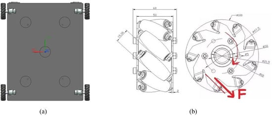
Figure 1.
Disinfection vehicle chassis’s mechanical structure. (a) Vehicle chassis structure schematic; (b) McNamee wheel schematic.
The design of the disinfection vehicle consists of a computational layer and a drive control layer, which is shown in Figure 2. The drive control layer uses an STM32 [26] microcontroller to collect motion data of the vehicle and receive control commands from the computational layer, thereby controlling the movement of the direct current motor. The computational layer uses Jetson Nano [27] as its computing core and deploys the ROS operating system on it. Data collected from the LIDAR is used to realize SLAM map building. The computational layer also interfaces with a depth camera to acquire image data and perform algorithm analysis. The specific hardware information is as follows.
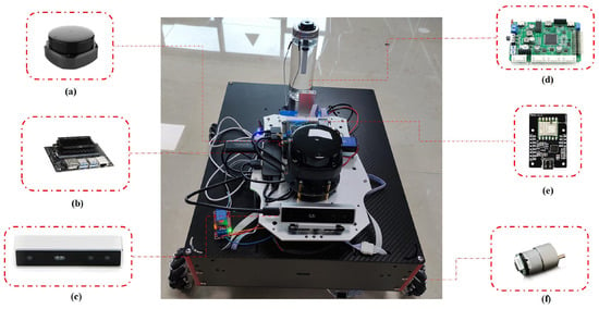
Figure 2.
The overall architecture and actual object of the intelligent disinfection vehicle. (a) Map building and perceptual obstacles: LIDAR; (b) Computational decision making: Jetson Nano; (c) Distance and image acquisition: Depth camera; (d) Motion control: STM32; (e) Position information: IMU sensor; (f) Execution unit: DC motor.
- (1)
- LIDAR Sensor: As shown in Figure 2a, we have selected the RPLIDAR-S2 LIDAR sensor. It has an angular resolution of up to 0.12 degrees, a maximum scan rate of 32,000 samples per second, a detection range of 0.05–30 m, operates on a 5V DC voltage, and can communicate through USB or UART.
- (2)
- Computing chip: As shown in Figure 2b, Jeston Nano is adopted in our design. It features a powerful GPU and CPU, a 128-core NVIDIA Maxwell GPU and a quad-core ARM Cortex-A57 CPU. It also has 4 GB LPDDR4 memory, a Gigabit Ethernet port, and support for dual 4K displays.
- (3)
- Depth camera: As shown in Figure 2c, we choose the Intel D415 device, which is a compact dual-lens depth camera with a resolution of 1920 × 1080, a frame rate of 30 fps, a depth range of 0.3–3.5 m, and a USB 3.0 connection.
- (4)
- Motion control: As shown in Figure 2d, the motion control is based on the STM32F103RC microcontroller. It features the ARM Cortex-M3 core, clocked at up to 72 MHz, with multiple communication interfaces, digital I/O pins, analog inputs, and an integrated RTC. It also supports up to 1 MB of Flash memory and 64 KB of SRAM, providing versatility and reliability for the vehicle.
- (5)
- Position sensor: As shown in Figure 2e, the MPU9250 is a 9-axis motion sensor that integrates a gyro, accelerometer, and magnetometer. It features high precision ADC and programmable filters with 3.3 V DC operation. The device has low power consumption, compact size, and high accuracy, making it suitable for our vehicle.
- (6)
- DC motor: As shown in Figure 2f, the rated voltage of the WHEELTEC MG513P10 DC optical encoder reduction motor is 12 V, and the rated current is 0.36 A. The stall current is 3.2 A, and the rated torque is 0.5 kg·cm. The stall torque is 1.9 kg·cm, and the power output is 4 W.
2.2. Module Design of the Disinfection Vehicle
The functional module of the intelligent disinfection vehicle proposed in this paper is shown in Figure 3, with three key functions: map construction, autonomous path navigation, and visual perception. First, accurate map construction is the key guarantee for path planning. By constructing an indoor map, the disinfection vehicle can understand its own location and static obstacle information in real time and execute motion based on the planned path. Secondly, path planning is divided into global path planning and local path planning. Global path planning plans the overall path in the map for the vehicle, while local path planning specifically addresses the problem of obstacle avoidance for dynamic obstacles. Finally, the visual perception function includes pedestrian detection and mask recognition. Pedestrian detection is used to stop the spraying when the disinfection vehicle approaches people in order to avoid an impact on pedestrians, and mask recognition is to remind pedestrians to wear masks correctly in crowded places, such as stations and exhibition halls, to ensure public health safety.
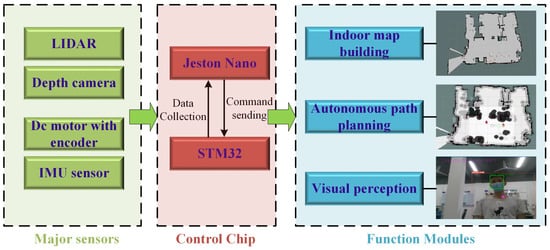
Figure 3.
Schematic diagram of the main functional modules of the disinfection vehicle.
2.2.1. Indoor Map Building Module
This paper presents the selection of the gmapping algorithm [28] for 2D raster map construction in the ROS (robot operating system) environment. Gmapping is a real-time SLAM (simultaneous localization and mapping) algorithm that uses LiDAR data to generate maps. The gmapping algorithm operates on the principle of using the Monte Carlo [29] tree algorithm to project laser data onto a 2D plane, and then calculating the relative positions between each frame of data to build a map.
To utilize the gmapping algorithm in ROS, the following steps should be taken: Firstly, install the ROS system and the gmapping package in ROS. Secondly, in the ROS system, gmapping generates maps in real-time by reading laser data and odometer data from the robot. Finally, for wheeled robots, ROS packages such as joy and teleop are used to control the motion of the robot, allowing for acquisition of more laser and odometer data, and ultimately, the construction of a complete map of the environment.
2.2.2. Autonomous Path Planning Module
In this study, an ROS operating system was utilized for autonomous robot navigation development. The Navigation function package in ROS was selected, which contains the A* path planning algorithm [16] and the DWA [30] local obstacle avoidance algorithm. In the ROS system, global path planning is used to plan the entire path, and local path planning is used to avoid dynamic obstacles while driving. The ROS system has a built-in local path-planning method, the DWA algorithm, which is used to avoid obstacles outside the map when they are detected by LiDAR. The main function of the navigation package is path planning, which achieves vector control of speed through the input of sensor data. The overall navigation package architecture of the ROS system is shown in Figure 4. The move_base node is the center of the package, serving as a powerful path planner. During navigation tasks, only the move_base node needs to be activated and provided with data to plan the path and speed. The ability of move_base to perform path planning is due to its inclusion of various plugins, such as the global_planner, local_planner, global_costmap, local_costmap, and recovery_behaviors. These plugins are responsible for finer tasks such as global planning, local planning, global mapping, local mapping, and recovery behavior.
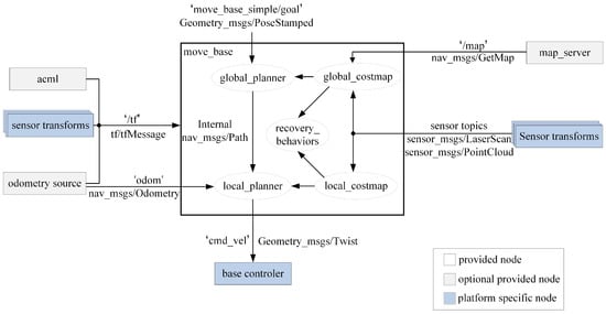
Figure 4.
Navigation frame diagram.
2.2.3. Visual Perception Module
Pedestrian detection is performed using the extremely lightweight YOLO v5s [31] model. YOLO (you only look once) is a real-time object detection system that is widely used in various applications. The YOLO v5s model is a compact version of the YOLO v5 architecture, which is designed to balance accuracy and speed. It uses a single convolutional neural network to predict the class and location of objects in an image or video. The model is trained on large datasets to learn to identify objects such as pedestrians, cars, buildings, and more. The YOLO v5 is able to identify the location of an object in an image, and combined with the depth information from the depth camera, we can calculate the distance between the object and the disinfection vehicle. With the detected center point of the pedestrian, we match the depth image with the RGB image to ensure the accuracy of the distance calculation. Using the object detection model, the coordinates of the upper left corner and the width and height of the rectangular box of the object can be obtained, so the center point of the rectangular box can be obtained after transformation. The calculation formula [31] is as follows:
where d represents the distance between the pedestrian and the depth camera, with units in millimeters (mm). represents the depth-map matrix generated by the depth camera, which is composed of distance information. i and j respectively represent the x and y coordinates of the center point of the pedestrian. Note that x and y are the x and y coordinates of the top left point of the pedestrian detection box, and w and h are the width and height of the detection box. By using the above method, we are able to accurately calculate the distance between the pedestrian and the disinfection vehicle in a real-time scene to ensure that the vehicle disinfects safely around the pedestrian.
When the disinfection vehicle detects pedestrians ahead who are not wearing masks, it will use a voice prompt to remind them to wear masks. The voice content is, “Please wear a mask”. We divide the mask detection into a two-stage task, first extracting the face region by the existing MTCNN [32] face recognition algorithm. Then, a lightweight ShuffleNet v2 [33] network is constructed to classify the mask-wearing behavior. MTCNN has efficient face detection capabilities and can accurately identify five key points, whereas ShuffleNet v2 is known for its smaller model size and higher running efficiency. It is particularly suitable for the requirement for fast and accurate classification. The mask classification data are self-built data, mainly by real collection and integration of web images. There were 8760 images, among which there were 4415 images wearing masks and 4345 images without masks. The training and test sets were divided in the ratio of 8:2. The classification metric we used was the overall classification accuracy. The accuracy rate is the ratio of the number of correctly predicted samples to the total number of samples and measures the accuracy of the model’s classification. The accuracy rate can be calculated by the formula.
where A is the accuracy rate, denotes true positive, denotes true negative, denotes false positive, and denotes false negative.
Pedestrian detection is a crucial feature that allows intelligent vehicles to detect and locate pedestrians in their surroundings. This feature helps prevent the inadvertent spraying of disinfectant on pedestrians, which could potentially cause harm or discomfort. With pedestrian detection, the vehicle is equipped to automatically halt the spraying of disinfectant when a pedestrian is detected, ensuring the safety and well-being of pedestrians in the vicinity. Mask detection, with voice reminders, prompts people to wear their masks properly, making it suitable for densely populated places such as train stations and exhibition halls. These visual functions are designed specifically for the disinfectant vehicle.
3. Global Path Planning for the Intelligent Disinfection Vehicle
3.1. Traditional A* Algorithm
The A* algorithm is a heuristic search algorithm used to find the global shortest path. It is widely used in the global path planning of moving robots. The A* algorithm combines the greedy best-first search (BFS) [34] algorithm and the Dijkstra [35] algorithm, with the basic principle being: First, define the Openlist and Closelist lists to store the nodes to be searched and the searched nodes, respectively. Starting from the starting point, put the nodes to be searched into the Openlist. Then, select the node with the lowest cost in the Openlist as the current processing node and move it to the Closelist. Next, generate the eight-neighborhood sub-nodes of the next current processing node and add them to the Openlist, while excluding the nodes in the Closelist and obstacles. Finally, calculate the cost value of each sub-node through the cost function , and choose the node with the minimum cost value as the new parent node and store it in the Closelist. Repeat the above search process until the end point is stored in the Closelist.
The heuristic function of the A* algorithm consists of the cost of the distance from the node to the starting point and the end point, calculated as follows:
where is the overall cost value of node n, is the actual cost from the starting point to node n, and is the estimated cost from node n to the end point. In the grid map of path planning, is the actual distance cost from the starting point to node n, with horizontal and vertical step costs of 10 and a diagonal step cost of 14. is the estimated distance from node n to the end point and is typically calculated using euclidean distance, Manhattan distance, diagonal distance, etc. This study used Manhattan distance, which is calculated as follows:
where and are the x and y coordinates of the current node n, and and are the x and y coordinates of the end point.
The traditional A* algorithm is superior in terms of search efficiency compared to BFS and Dijkstra algorithms, but still has certain limitations. In a scenario with densely distributed obstacles, the path planned by the A* algorithm is shown in Figure 5. It can be seen that the planned path has cases of touching the edges of obstacles and crossing the corners of obstacles. Therefore, the traditional A* algorithm is unable to meet the obstacle-avoidance requirements of the moving robot in actual scenarios, and there are deficiencies in terms of safety. In addition, the planned path has problems such as many path turning points, redundant nodes, and insufficient path smoothness.
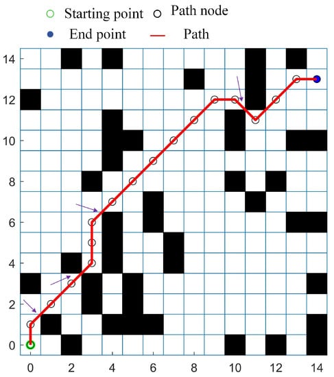
Figure 5.
An example of disadvantages of paths generated by the traditional A* algorithm.
3.2. Improved A* Algorithm
3.2.1. Optimization of Search Point Selection Strategy
To address the issue of low path safety in the traditional A* algorithm, this research proposes an improved search-point selection strategy. By eliminating obstacle-adjacent nodes in eight surrounding sub-nodes, the planned path can maintain a certain level of safety distance from the obstacles. The node-search process of the traditional A* algorithm for path planning is shown in Figure 6. In the figure, G is the goal node, S is the parent node, and ob is the obstacle. The eight directions in which the current parent node S can expand the search are , , , , , , , and . When searching for subsequent nodes, is determined to be an obstacle, so the subsequent nodes will automatically search in seven directions, which are , , , , , , and .
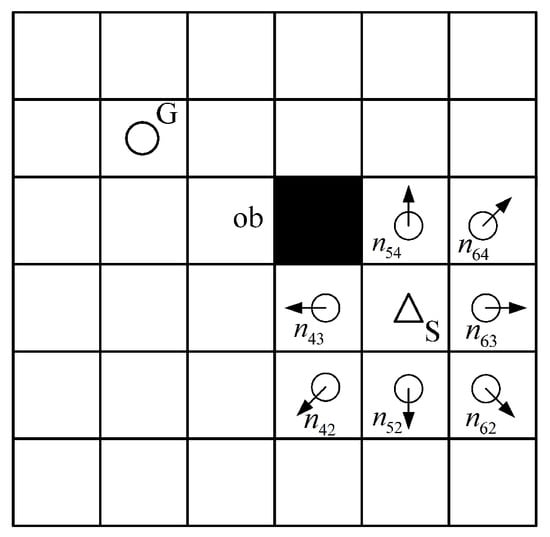
Figure 6.
Example diagram of an extended search direction.
The search strategy proposed in this study discards nodes in two directions adjacent to an obstacle when there is an obstacle in the eight neighboring sub-nodes. As shown in Figure 7, the 3 × 3 grid map is composed of elements , as follows:
where represents a blank area and represents an obstacle. For horizontal and vertical direction searches, when searching to node , since , node is an obstacle; the nodes and , which have a common adjacent edge with it, will not be put into the Openlist. The search node becomes the set S.
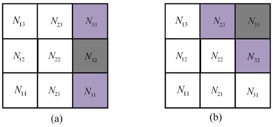
Figure 7.
Improved eight-neighborhood sub-node search. (a) Horizontal or vertical search; (b) Diagonal direction search.
Similarly, during diagonal direction searches, when searching to node , since node is an obstacle, nodes and that have a common adjacent edge with it will not be put into the search list, and the remaining search direction node set S is put into the Openlist.
Finally, the node with the minimum value is selected as the new parent node through the cost function, so that the planned new path can maintain a safe distance from obstacles.
3.2.2. Path Smoothing Based on the Floyd Algorithm
In addressing the problems of excessive path redundancy nodes and difficulty in turning in the traditional A* algorithm for the path planning of mobile robots, we utilized the Floyd [36] algorithm to smooth the safe path presented in Section 3.2.1, allowing the mobile robot to improve efficiency while maintaining safety.
The Floyd algorithm, also known as the insert-point algorithm, is capable of finding the shortest distance between any two nodes. The core idea of the Floyd algorithm is to calculate a weighted adjacency matrix and derive the shortest path. If a path exists from node to , the length of the path from to is denoted as . Since this path is not necessarily the shortest path, n iterations are needed. In this research, the node optimization principle of Floyd for the path is shown in Figure 8.
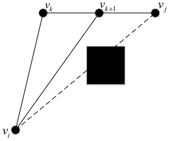
Figure 8.
Principle of the Floyd algorithm.
The length of the path from point to point is , and if there is an obstacle between points and , the length between points and is infinite; that is, =∞. When inserting between and , if Equation (9) is satisfied, then Equation (10) holds, and the path is from to and then to . If Equation (11) is satisfied, then Equation (12) holds, and the path is from to and then to . Thus, the shortest path from node to node is from to and then to .
In this study, the Floyd algorithm is used to optimize the path redundancy nodes. The specific steps are as follows:
- Step 1: Take the weighted adjacency matrix as the initial value of the distance matrix , that is, . Then, define the initial matrix to record information about the insertion of intermediate nodes (k = 1, ..., n).
- Step 2: represents the shortest path length between any two nodes when passing through node ; that is, . Through the above calculation method, update the distance matrix; that is, .
- Step 3: Iterate from step 2 by setting . The elements of the distance matrix represent the shortest path length between any two nodes after passing through nodes .
- Step 4: By extrapolating from Step 3, when , the solution of the distance matrix is obtained. The elements, represents the shortest path length from node to node through intermediate nodes . The matrix P records the nodes of the shortest path.
Figure 9a shows the path generated by the A* algorithm with safety distance optimization, and Figure 9b shows the further-optimized path using the Floyd algorithm. It can be seen that after using the Floyd algorithm, the numbers of turning points and redundant nodes in the path decreased, which is more in line with the path requirements of the moving robot in actual situations.
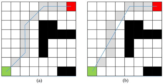
Figure 9.
The path optimized utilizing the Floyd algorithm. (a) A* algorithm path after safety distance optimization; (b) The optimized path.
3.2.3. Algorithm Flow
The flow chart of the improved A* algorithm proposed in this study is shown in Figure 10. The difference between the proposed algorithm and the traditional A* algorithm is as follows: (1) The search strategy of child nodes is improved on the basis of the traditional A* algorithm, and the search directions of neighboring child nodes of obstacles are deleted, so that the newly planned path maintains a certain safe distance from the obstacles. (2) The Floyd algorithm is used to smooth the path optimization, eliminate redundant path nodes, and retain key path points.
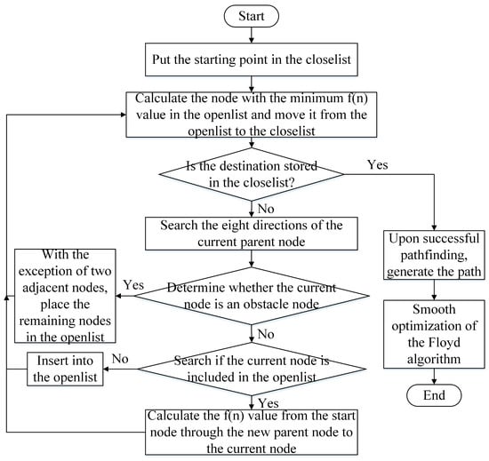
Figure 10.
The optimized path by utilizing the Floyd algorithm.
4. Experiments and Results
4.1. Experimental Environment
In the simulation experiments, the computational hardware used in this study was configured as follows: the CPU model was an Intel Core I5-7200U with a frequency of 2.5 GHz and running memory of 8 GB. The software configuration was a 64-bit Windows 10 operating system, and the programming and simulation platform used was MATLAB 2016a.
4.2. Path Simulation and Comparison
In order to validate the efficacy of the algorithm, simulation experiments were conducted in three different scenes. The path length, number of nodes, safety distance, and number of turns were used as evaluation metrics for the path. The results were compared with those of the traditional A* algorithm, references [23,37], and the proposed method, as follows:
In scene 1, the grid map size was set to 16 × 16 with an obstacle coverage of 22%, and the starting point was located at (0,0) and the ending point at (14,13). The simulated paths before and after the improvement are shown in Figure 11. It can be observed that the traditional A* algorithm produces a large number of redundant nodes and may cross the diamond-corners of obstacles. However, the proposed algorithm significantly reduces the number of redundant nodes and turning points while incorporating a safety margin.
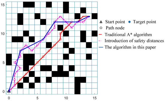
Figure 11.
Comparison of the paths in scene 1 before and after algorithm improvement.
Scene two was set to have a grid map size of 26 × 26, with an obstacle coverage rate of 25%, starting at the coordinate (0, 0), and ending at (24, 23). Scene three was set to have a grid map size of 36 × 36, with an obstacle coverage rate of 25%, ending at (34, 33). The comparison of the path simulation before and after the algorithm improvement in scene two and scene three is shown in Figure 12 and Figure 13, respectively. It can be seen that the proposed method still achieved similar experimental results as in scene one, lthat is, the proposed improvement can reduce redundant nodes and turning points while increasing the safety distance.
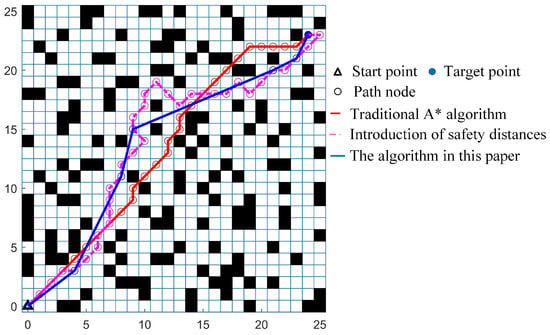
Figure 12.
Comparison of the paths in scene 2 before and after the algorithm’s improvement.
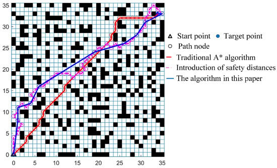
Figure 13.
Comparison of the paths in scene 3 before and after the algorithm’s improvement.
In summary, the path with the introduction of a safety distance can achieve a safe distance from obstacles, but with a greater length, a higher number of nodes, and a higher number of turns. The Floyd algorithm is used to further optimize the path, resulting in better improvement in terms of path length, number of nodes, and number of turns. The improved method can maintain a certain safe distance from obstacles while only increasing the path length a small amount, and is superior in terms of number of nodes and number of turns compared to the traditional A* algorithm. Thus, it is indicated that the proposed algorithm is effective.
4.3. Comparison and Analysis of Algorithms
To further demonstrate the advantages of the proposed algorithm, experiments were conducted to compare the proposed algorithm with the traditional A* algorithm, as well as references [23,37], in three map scenarios. The comparison of the algorithms’ paths in each scenario is shown in Figure 14, and the specific performance indicators are shown in Table 1.
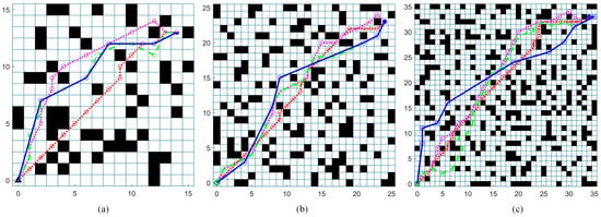
Figure 14.
Comparison of the paths of the four algorithms in different scenes. (a) Scene 1; (b) Scene 2; (c) Scene 3. The red dotted line represents the traditional A* algorithm, the pink dotted line represents the one that we implemented based on the algorithm proposed in reference [37], the green dotted line represents the one that we implemented based on the algorithm proposed in reference [23], and the blue solid line represents the method proposed in this paper.

Table 1.
Performance comparison of the proposed algorithm with other methods. L is the path length, N is the number of path nodes, D is the safety distance, and T is the number of turning points.
As can be seen, the traditional A* algorithm and the reference [37] do not consider the safe distance, whereas the method in this paper has a closest average distance to obstacles of approximately 0.463, which is slightly increased compared to the method in [23]. The improvements to the A* algorithm made by the authors of [23,37], and the method in this paper, all increase the length of the path, but the increase in the path length is minimal in the method in this paper. All three methods achieve a reduction in the number of path nodes, and among them, the method in this paper reduces the number of path nodes by 61.82% and 62.01% on average compared to the references [23,37] in three scenarios, respectively. Compared to the traditional A* algorithm, the methods from references [23,37] increase the number of turns, whereas the method in this paper can reduce the number of turns. In addition, in large maps, the number of turns can be significantly optimized by the method; for example, in a 36 × 36 map, the number of turns is reduced by 50% and 58.79% compared to reference [23,37], respectively. Therefore, while only slightly increasing the length of the path, the method in this paper not only increases the distance from obstacles but also optimizes the number of search nodes and turning points.
5. System Test
5.1. Slam Map Building
Before conducting the path-planning task, it was necessary to carry out the testing of the mapping module based on the Gmapping algorithm. We chose Rviz for visualization, which is an open-source 3D visualization tool for displaying robot data and maps. First, the intelligent vehicle was controlled to move back and forth in the indoor setting using a mobile phone application, and then the mapping construction situation in Rviz was observed. Then, if a certain area was found to be unmapped, the vehicle was made to move back and forth in that area until the mapping was completed. Finally, we obtained a grid map that matched the actual scene and saved it locally.
Figure 15 displays the results of our indoor mapping effort, which demonstrates that the employed Gmapping algorithm is capable of constructing a grid map that is consistent with the actual indoor scenario, and thus can serve as the basis for future path planning.
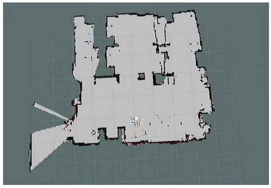
Figure 15.
Building test on Rviz.
5.2. Global Path Planning
Figure 16 displays the path-planning results of the study conducted in a real-world environment. It can be seen that through the designed global path-planning method, the intelligent disinfection vehicle successfully searched for a global path. The vehicle is able to avoid obstacles along the planned path and accurately reach the destination.
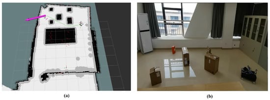
Figure 16.
The global path planning of the disinfection vehicle in an actual situation. (a) Global path visualization on Rviz; (b) Disinfection vehicles running in real scene.
5.3. Visual Perception
For the mask classification task, in the training process, we utilized the model weights pre-trained on the ImageNet [38] dataset for transfer learning in the initialization of the model weights. Figure 17 shows the comparison of the model accuracy before and after using transfer learning. E denotes the training cycle, and A denotes the accuracy on the test set. It can be seen that the accuracy of the classification model reached 99.02% by transfer learning, which is a 6.8% improvement compared to the original strategy.
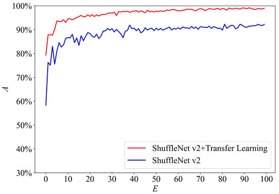
Figure 17.
Training curve of ShuffleNet v2 on the mask classification dataset.
Figure 18 demonstrates the mask-recognition and pedestrian-detection results in indoor scenarios. The results show that the model used in this study can effectively detect mask wearing status in indoor scenarios, and the detection results are consistent with the actual situation. For pedestrian detection, the predicted boxes are well aligned with the true boxes, and the range of the predicted boxes is relatively accurate. Additionally, the depth camera used in this study can accurately measure the distance information of the target. Therefore, the model used in this study can quickly complete mask recognition and pedestrian detection in indoor environments, proving the effectiveness of the designed function.
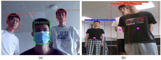
Figure 18.
Mask-wearing recognition and pedestrian-detection (including distance measurement). (a) Visualization of mask detection; (b) Visualization of pedestrian detection and distance measurement.
5.4. Disinfection Vehicle System Demonstration
The designed intelligent disinfection vehicle, as shown in Figure 19 and Figure 20, can accurately map indoor scenes and cruise for disinfection based on the test results of SLAM mapping, fixed-point navigation, object detection, and remote central control. In addition, the lightweight and effective mask recognition and pedestrian target detection methods are effective explorations in computer vision for epidemic prevention and control. Finally, the remote operation software is simple and effective, achieving interface interaction and result visualization. In conclusion, the overall functionality of the system is satisfactory and is capable of fulfilling the requirements of this project.
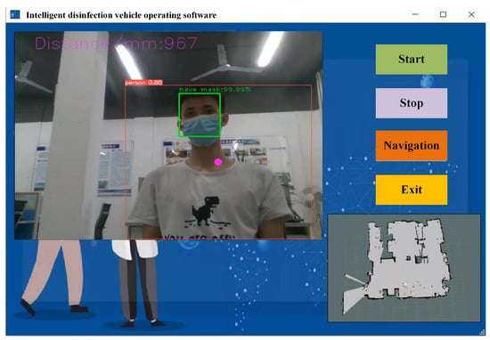
Figure 19.
Software interface test.
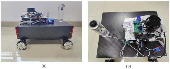
Figure 20.
Presentation of the overall appearance of the proposed system. (a) Side view of overall structure; (b) Top view of overall structure.
The disinfection vehicle offers numerous advantages in the area of epidemic prevention and control. Its precise mapping and navigation capabilities ensure an efficient and comprehensive disinfection process. Additionally, its mask recognition and pedestrian detection functions provide extra safety measures to protect individuals during the cleaning process. Furthermore, the vehicle’s remote operation features allow for easy control, even from a distance. In conclusion, the intelligent disinfection vehicle represents a valuable solution for enhancing hygiene and safety in public spaces.
6. Conclusions
The aim of this research was to examine the design and method of path planning for an intelligent disinfection vehicle system. With the growing concern of infectious diseases, it is becoming imperative to ensure the proper disinfection of indoor spaces. Conventional manual disinfection methods are tedious and require a lot of manual labor; thus, the development of intelligent disinfection vehicle systems, as a more efficient solution, has become necessary.
In this research, the robot operating system (ROS) was used as the control platform, and simultaneous localization and mapping (SLAM) technology was applied to create an indoor scene map. Based on this information, a novel path-planning method that integrates the A* algorithm and the Floyd algorithm is proposed. The experimental results show that the proposed algorithm reduces path redundant nodes by an average of 70.43% and turning points by an average of 31.1% compared to the conventional A* algorithm under the condition that the nearest distance to the obstacle is about 0.463 on average. Compared with the references [23,37], the path length of the algorithm in this paper was shorter by 2.06% and 6.29% on average; the path redundancy points were reduced by 61.82% and 62.01% on average; and the turnover points were reduced by 50% and 56.68% on average. Our method ensures the safety, efficiency, and smoothness of the vehicle’s path while considering the avoidance of obstacles and other potential dangers. Furthermore, the vehicle should be equipped with a mask recognition and pedestrian detection algorithm to increase safety. This allows vehicles to stop in time during the disinfection process to avoid spraying disinfectant directly onto pedestrians, and ensures that they are wearing masks, which is paramount in the current global health situation.
Our future work would focus on exploring similar technologies used in the development of intelligent robots to improve the development of intelligent disinfection robots. This includes examining various methods, algorithms, and approaches, such as machine learning, computer vision, and natural language processing, that can be adapted for use in disinfection robots. In addition, it is also worth exploring how to fuse vision detection results for dynamic obstacle avoidance.
Author Contributions
Conceptualization, L.C. and H.Y.; Methodology, L.C.; Software, L.C.; Validation, L.C.; Resources, L.C. and Z.F.; Writing—Review & Editing, L.C.; Supervision, H.Y.; Project administration, H.Y.; Writing original draft, H.Y.; Funding acquisition, H.Y.; Formal analysis, Z.C. and Z.F.; Data curation, Z.C. and Z.F.; Investigation, Z.C. All authors have read and agreed to the published version of the manuscript.
Funding
This work was supported by the National Natural Science Foundation of China (No. 12161043), the Natural Science Foundation of Jiangxi Province (20192BAB201007), and the Jiangxi Postgraduate Innovation Special Fund Project (YC2022-S648).
Institutional Review Board Statement
Not applicable.
Informed Consent Statement
Not applicable.
Data Availability Statement
Not applicable.
Acknowledgments
We would also like to extend our thanks to the three anonymous reviewers for their valuable comments and suggestions, which have greatly improved the quality of this manuscript.
Conflicts of Interest
The authors declare no conflict of interest.
References
- Xu, C.; Yu, C.W.F. Prevention and control of COVID-19 transmission in the indoor environment. Indoor Built Environ. 2022, 31, 1159–1160. [Google Scholar] [CrossRef]
- Yang, G.Z.; J. Nelson, B.; Murphy, R.R.; Choset, H.; Christensen, H.; H. Collins, S.; Dario, P.; Goldberg, K.; Ikuta, K.; Jacobstein, N.; et al. Combating COVID-19—The role of robotics in managing public health and infectious diseases. Sci. Robot. 2020, 5, eabb5589. [Google Scholar] [CrossRef] [PubMed]
- Megahed, N.A.; Ghoneim, E.M. Indoor Air Quality: Rethinking rules of building design strategies in post-pandemic architecture. Environ. Res. 2021, 193, 110471. [Google Scholar] [CrossRef] [PubMed]
- Hussain, K.; Wang, X.; Omar, Z.; Elnour, M.; Ming, Y. Robotics and Artificial Intelligence Applications in Manage and Control of COVID-19 Pandemic. In Proceedings of the 2021 International Conference on Computer, Control and Robotics (ICCCR), Shanghai, China, 8–10 January 2021; pp. 66–69. [Google Scholar] [CrossRef]
- Huang, S.P.; Neo, J.F.; Chen, Y.Y.; Chen, C.B.; Wu, T.W.; Peng, Z.A.; Tsai, W.T.; Liou, C.Y.; Sheng, W.H.; Mao, S.G. Ultra-Wideband Positioning Sensor with Application to an Autonomous Ultraviolet-C Disinfection Vehicle. Sensors 2021, 21, 5223. [Google Scholar] [CrossRef]
- Roelofs, S.; Landry, B.; Jalil, M.K.; Martin, A.; Koppaka, S.; Tang, S.K.; Pavone, M. Vision-based Autonomous Disinfection of High-Touch Surfaces in Indoor Environments. In Proceedings of the 2021 21st International Conference on Control, Automation and Systems (ICCAS), Jeju, Republic of Korea, 12–15 October 2021; pp. 263–270. [Google Scholar] [CrossRef]
- Reddy, S.V.; Prakash, T.M.; Naik, J.S.; Ramakrishnan, S.; Raj, J.J.D.; Bhargavi, B. Designing of Six Wheel Robotic Vehicle for Instant Disinfection and Sanitization. In Proceedings of the 2022 Trends in Electrical, Electronics, Computer Engineering Conference (TEECCON), Bengaluru, India, 26–27 May 2022; pp. 18–24. [Google Scholar] [CrossRef]
- Zhang, C.; Yin, L.; Zhang, B. Design of Spraying Disinfection Robot Based on Video Teleoperation. In Proceedings of the 2021 4th International Conference on Robotics, Control and Automation Engineering (RCAE), Wuhan, China, 4–6 November 2021; pp. 251–255. [Google Scholar] [CrossRef]
- Esposito, S.; Cotugno, N.; Principi, N. Comprehensive and safe school strategy during COVID-19 pandemic. Ital. J. Pediatr. 2021, 47, 1–4. [Google Scholar] [CrossRef]
- Bhalla, S.; Melnekoff, D.T.; Aleman, A.; Leshchenko, V.; Restrepo, P.; Keats, J.; Onel, K.; Sawyer, J.R.; Madduri, D.; Richter, J.; et al. Patient similarity network of newly diagnosed multiple myeloma identifies patient subgroups with distinct genetic features and clinical implications. Sci. Adv. 2021, 7, eabg9551. [Google Scholar] [CrossRef] [PubMed]
- Chen, Z.; Yang, J.; Chen, L.; Jiao, H. Garbage classification system based on improved ShuffleNet v2. Resour. Conserv. Recycl. 2022, 178, 106090. [Google Scholar] [CrossRef]
- Chen, Z.; Guo, H.; Yang, J.; Jiao, H.; Feng, Z.; Chen, L.; Gao, T. Fast vehicle detection algorithm in traffic scene based on improved SSD. Measurement 2022, 201, 111655. [Google Scholar] [CrossRef]
- Feng, Z.; Yang, J.; Chen, L.; Chen, Z.; Li, L. An Intelligent Waste-Sorting and Recycling Device Based on Improved EfficientNet. Int. J. Environ. Res. Public Health 2022, 19, 15987. [Google Scholar] [CrossRef]
- You, K.; Qiu, G.; Gu, Y. Rolling Bearing Fault Diagnosis Using Hybrid Neural Network with Principal Component Analysis. Sensors 2022, 22, 8906. [Google Scholar] [CrossRef]
- Chen, Z.; Yang, J.; Feng, Z.; Chen, L.; Li, L. BiShuffleNeXt: A lightweight bi-path network for remote sensing scene classification. Measurement 2023, 209, 112537. [Google Scholar] [CrossRef]
- Duchoň, F.; Babinec, A.; Kajan, M.; Beňo, P.; Florek, M.; Fico, T.; Jurišica, L. Path Planning with Modified a Star Algorithm for a Mobile Robot. Procedia Eng. 2014, 96, 59–69. [Google Scholar] [CrossRef]
- Sun, W.; Lv, Y.; Tang, H.; Xue, M. Mobile robot path planning based on an improved A* algorithm. Robot 2018, 40, 903–910. [Google Scholar] [CrossRef]
- Liu, Z.H.; Zhao, J.; Liu, C. Path planning of indoor mobile robot based on improved A* algorithm. Comput. Eng. Appl. 2021, 57, 186–190. [Google Scholar] [CrossRef]
- Chi, X.; Li, H.; Fei, J. Research on robot random obstacle avoidance method based on fusion of improved A* algorithm and dynamic window method. Chin. J. Sci. Instrum. 2021, 42, 132–140. [Google Scholar] [CrossRef]
- Jiang, H.; Sun, Y. Research on global path planning of electric disinfection vehicle based on improved A* algorithm. Energy Rep. 2021, 7, 1270–1279. [Google Scholar] [CrossRef]
- Wang, B.; Nie, J.J.; Li, H.Y. Based on optimized A* and dynamic window approach for mobile robot path planning. Comput. Integr. Manuf. 2022, 3, 1–17. [Google Scholar]
- Wang, H.B.; Yin, P.H.; Zheng, W. Mobile Robot Path Planning Based on Improved A* Algorithm and Dynamic Window Method. Robot 2020, 42, 346–353. [Google Scholar] [CrossRef]
- Zhong, X.; Tian, J.; Hu, H.; Peng, X. Hybrid path planning based on safe A* algorithm and adaptive window approach for mobile robot in large-scale dynamic environment. J. Intell. Robot. Syst. 2020, 99, 65–77. [Google Scholar] [CrossRef]
- Bayili, S.; Polat, F. Limited-Damage A*: A path search algorithm that considers damage as a feasibility criterion. Knowl.-Based Syst. 2011, 24, 501–512. [Google Scholar] [CrossRef]
- Sun, Z.; Xie, H.; Zheng, J.; Man, Z.; He, D. Path-following control of Mecanum-wheels omnidirectional mobile robots using nonsingular terminal sliding mode. Mech. Syst. Signal Process. 2021, 147, 107128. [Google Scholar] [CrossRef]
- Jacko, P.; Bereš, M.; Kováčová, I.; Molnár, J.; Vince, T.; Dziak, J. Remote IoT Education Laboratory for Microcontrollers Based on the STM32 Chips. Sensors 2022, 22, 1440. [Google Scholar] [CrossRef] [PubMed]
- Cass, S. Nvidia makes it easy to embed AI: The Jetson nano packs a lot of machine-learning power into DIY projects - [Hands on]. IEEE Spectr. 2020, 57, 14–16. [Google Scholar] [CrossRef]
- Guan, R.P.; Ristic, B.; Wang, L.; Palmer, J.L. KLD sampling with Gmapping proposal for Monte Carlo localization of mobile robots. Inf. Fusion 2019, 49, 79–88. [Google Scholar] [CrossRef]
- Świechowski, M.; Godlewski, K.; Sawicki, B.; Mańdziuk, J. Monte Carlo tree search: A review of recent modifications and applications. Artif. Intell. Rev. 2022, 1–66. [Google Scholar] [CrossRef]
- Fox, D.; Burgard, W.; Thrun, S. The dynamic window approach to collision avoidance. IEEE Robot. Autom. Mag. 1997, 4, 23–33. [Google Scholar] [CrossRef]
- Kim, J.H.; Kim, N.; Park, Y.W.; Won, C.S. Object Detection and Classification Based on YOLO-V5 with Improved Maritime Dataset. J. Mar. Sci. Eng. 2022, 10, 377. [Google Scholar] [CrossRef]
- Xiang, J.; Zhu, G. Joint Face Detection and Facial Expression Recognition with MTCNN. In Proceedings of the 2017 4th International Conference on Information Science and Control Engineering (ICISCE), Changsha, China, 21–23 July 2017; pp. 424–427. [Google Scholar] [CrossRef]
- Ma, N.; Zhang, X.; Zheng, H.T.; Sun, J. ShuffleNet V2: Practical Guidelines for Efficient CNN Architecture Design. In Proceedings of the European Conference on Computer Vision (ECCV), Munich, Germany, 8–14 September 2018. [Google Scholar]
- Dechter, R.; Pearl, J. Generalized best-first search strategies and the optimality of A. J. ACM 1985, 32, 505–536. [Google Scholar] [CrossRef]
- Wang, H.; Yu, Y.; Yuan, Q. Application of Dijkstra algorithm in robot path-planning. In Proceedings of the 2011 Second International Conference on Mechanic Automation and Control Engineering, Inner Mongolia, China, 15–17 July 2011; pp. 1067–1069. [Google Scholar] [CrossRef]
- Lyu, D.; Chen, Z.; Cai, Z.; Piao, S. Robot path planning by leveraging the graph-encoded Floyd algorithm. Future Gener. Comput. Syst. 2021, 122, 204–208. [Google Scholar] [CrossRef]
- Huai, C.F.; Guo, L.; Jia, X.Y. Improved A* Algorithm and Dynamic Window Method for Robot Dynamic Path Planning. Comput. Eng. Appl. 2021, 57, 244–248. [Google Scholar] [CrossRef]
- Krizhevsky, A.; Sutskever, I.; Hinton, G.E. ImageNet Classification with Deep Convolutional Neural Networks. Commun. ACM 2017, 60, 84–90. [Google Scholar] [CrossRef]
Disclaimer/Publisher’s Note: The statements, opinions and data contained in all publications are solely those of the individual author(s) and contributor(s) and not of MDPI and/or the editor(s). MDPI and/or the editor(s) disclaim responsibility for any injury to people or property resulting from any ideas, methods, instructions or products referred to in the content. |
© 2023 by the authors. Licensee MDPI, Basel, Switzerland. This article is an open access article distributed under the terms and conditions of the Creative Commons Attribution (CC BY) license (https://creativecommons.org/licenses/by/4.0/).