Abstract
An equivalent nonuniform transmission line model for electromagnetic radiation in free space is developed. By properly defining a voltage and a current associated with the transverse component of the mode fields, a kind of telegrapher’s equation is derived for each spherical harmonic mode in frequency domain. Based on the equivalent distribution inductance and capacitance, the local characteristic impedance and phase velocity are derived. For each spherical mode, a cutoff spherical surface and an associated cutoff radius are introduced to separate the space into an evanescent region and a propagating region. A spherical mode field decays approximately exponentially in the evanescent region and experience local reflection in the propagating region. The proposed model may provide an intuitive illustration for the radiation process in free space.
1. Introduction
The electromagnetic radiation problem has been extensively investigated over the past century. Except several issues concerning the electromagnetic powers and energies [1,2,3], the theoretic aspects of the electromagnetic radiation of antennas are well understood by researchers and engineers. In free space, the radiation fields of a current source distribution in a bounded region can be directly calculated with integrals involving the dyadic Green’s function. These integrals generally have to be performed over the source region with some kind of numerical method. It is very efficient to illustrate the radiation patterns of specified radiation sources with numerical results. Nowadays, numerical tools are powerful for designing antennas with some kind of optimization algorithms or simply with parameter scanning. However, in many practical applications, such as designing antennas with better directivity, higher efficiency, or wider bandwidth, it may require more insightful information and interpretation of the radiation process than those the numerical solutions can provide. Analytical and semi-analytical methods are still very important. They can provide theoretical bases for judging the correctness and evaluating the accuracy of numerical algorithms. In general, analytical methods can be used to catch the characteristic property of a system, to predict the boundaries and limitations of numerical methods, or can even provide clues for new analytic approaches or design concepts.
The spherical mode expansion method has been applied for electromagnetic scattering analysis, antenna designs, and measurements for decades [4,5,6]. It may be traced back to Mie series expansion method proposed in 1908 [7]. Under plane wave excitation, the scattering fields of perfectly electrically conducting (PEC) spheres, multilayer dielectric spheres, etc., can be analytically solved with Mie series expansion. These theoretical results have played a very important role in revealing the basic electromagnetic scattering principles. They have also been used as fundamental references for evaluating the accuracy of numerical algorithms in computational electromagnetics [8]. The widely used T-matrix method is generally based on spherical mode expansion [9]. It is efficient to provide accurate solutions to the scattering fields or radiation fields of small objects or object groups [10]. Although using spherical mode expansion method alone may be not efficient in analyzing large-scale systems such as antenna arrays with complex structures, it can be used in conjunction with other numerical methods to improve their efficiency and accuracy [11].
In this paper, we will revisit the spherical mode expansion solutions to the fields of a bounded source in free space. By comparing the governing equation of the transverse electric field and the transverse magnetic field of a spherical mode with the standard telegrapher’s equation, we proposed a nonuniform transmission line (NTL) model for the spherical modes in frequency domain. The electromagnetic radiation process may be illustrated more intuitively with the NTL model.
Hereafter, we begin with a brief introduction of the spherical mode expansion solutions to the electromagnetic fields in free space, together with the equivalent circuit model proposed by Chu [12]. The NTL model will be developed in Section 2. Some special issues are discussed in Section 3. Finally, the conclusions are summarized in Section 4.
In the conventional spherical coordinate system shown in Figure 1a, the electric field and the magnetic field at the position are denoted by and , respectively. Assume that they are generated by a source distribution in a bounded region in vacuum. The vector spherical basis functions, derived by Hansen [13] and adopted by many authors [14,15,16,17,18], consist of two sets of solenoidal functions called the functions and the functions and one set of irrotational eigenfunctions called the functions. They form a complete basis for the functional space of the radiation fields of the source [12,13,14,15,16,17,18]. The radiation fields of a bounded source in free space can be expanded with the three set of eigenfunctions. Especially in the region outside the source area, the spherical expansion of the radiation fields only involves the two solenoidal function sets. Due to the orthogonality feature of the eigenfunctions, the mode fields are orthogonal and can be handled separately.
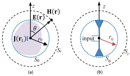
Figure 1.
The electromagnetic radiation. (a) A source in a bounded region; (b) antenna with symmetrical structure.
Let with a radius of denote the smallest sphere containing the source region. The electric and magnetic fields outside can be expanded with mode and mode,
where n is the degree and m the order of the mode, respectively.
The electromagnetic fields of the spherical mode can be explicitly expressed with the three sets of vector eigenfunctions. As can be found in the literature [12,13,14,15,16,17,18], the fields of the spherical modes in frequency domain outside the source area can be expressed as
and for spherical modes, we have
The coefficients and in (2)–(5) are determined by the sources in enclosed by . k is the wavenumber and is the intrinsic impedance in free space. represents the spatial phase shift. is the spherical Hankel function of the second kind. We use the notation for throughout this paper. The spherical coordinate r, and are defined in their usual way, and their unit vectors are respectively denoted by , , and . It is understood that the expressions may be slightly different in the constant of each term in different studies.
The normalized vector harmonics are expressed as
where is the harmonic function on the unit sphere,
and is the associated Legendre function. The normalized spherical harmonics form a complete set of orthogonal basis functions,
in which denotes .
At region far away from the source, . Making use of the asymptotic expansions of the spherical Hankel functions for large arguments, the far fields of the spherical modes can be approximately considered as spherical TEM waves with radiation patterns described by the corresponding spherical harmonic functions. However, the behavior of the near zone fields has not been revealed so intuitively. By numerically evaluating the amplitudes or some other quantities related to spherical Hankel functions [19,20,21,22], the fields of the mode with degree n may be roughly considered to decay exponentially with radius r if is satisfied. When applying fast multipole methods (FMM) for electromagnetic problems [22], the empirical criterion of is often used to determine the truncation number of spherical modes for a given distance and an accuracy-related constant, .
An equivalent circuit model was proposed by Chu in 1948 [12]. As shown in Figure 1b, an antenna with symmetrical structure is completely contained in the sphere . The and modes are analyzed in [12] (where they are respectively referred to as and ). Each mode is equipped with a two-port equivalent circuit model. The input port of the equivalent circuit is , while the other port is , the concentric spherical surface when . is considered to be terminated with the intrinsic impedance in free space and is perfectly matched. For modes, the normalized voltage and current are defined on the basis of the electric field and magnetic field on the input port ((7) in [12]), respectively,
where is a mode-dependent constant, and . The normalized input impedance is then expressed using the ratio of the voltage and current,
The modes were addressed in a similar way in [12]. The radiation power, energies and Q factors of the mode are evaluated accordingly. Furthermore, the normalized impedance of or the normalized admittance of is expanded with a continuous fraction that can help us to establish an equivalent circuit consisting of cascaded inductances, capacitances, and a termination of a unitary resistance. All the elements in the equivalent circuit are normalized with the intrinsic impedance of free space. This circuit model is very popular and has been widely used to predict the minimum radiation Q-factor of an antenna bounded in a small sphere. However, it mainly describes the characteristics on the input port and does not provide intuitive information about the radiation process from to .
In this paper, a nonuniform transmission line (NTL) model for the radiation process from to is developed, in which serves as the input port and serves as the matched terminal port. The equivalent voltage and current at any concentric sphere with a radius r are properly defined. The governing differential equation is obtained and found to be similar to the conventional telegrapher’s equation [23] except that the equivalent distribution inductance or the distribution capacitance is dependent on . It can be interpreted as a kind of nonuniform transmission line or a nonuniform waveguide. The generalized input impedance at any position on the NTL can be obtained, and the normalized impedance defined by Chu is simply the special case at the input port , where . It will be shown that the NTL model can provide more intuitive interpretation for the radiation process from to than conventional theories.
2. Nonuniform Transmission Line Model
In order to develop the NTL model for the radiation problem, we will multiply the mode fields with r and find the relationship between the transverse electric field and the rotated transverse magnetic field.
2.1. Mode
According to (2) and (3), we can write the transverse components of the mode as follows:
in which the relationship of has been applied. For the sake of convenience, in the expressions we have dropped the constant that has been included in (2) and (3) but still use the same for the expansion coefficient. The subscript represents transverse component. Note that both r and are used in the derivation for the sake of brevity. Taking the derivative of both side of (10) with respect to r, and making use of the relationship [19] of
we obtain
Taking the derivative of both side of (11) with respect to r, we obtain
Define the equivalent voltage and current on a concentric sphere with radius r as
Then the electromagnetic fields can be expressed by
Making use of the Wronskian relationship
we can verify that the radiation power crossing the sphere can be correctly calculated with the voltage and current,
Substituting (17) and (18) into (13) and (14) gives the governing differential equation for the mode,
Note that (20) is valid for all in free space. It can be extended to a uniform lossless medium by replacing the wavenumber and the intrinsic impedance in the formulation with those in that medium. Obviously, (20) is similar to the telegrapher’s equation that the voltage and current satisfy on a transmission line with a distribution inductance and a distribution capacitance [23,24,25],
Comparing (20) with (21), we can introduce an equivalent distribution inductance and an equivalent distribution capacitance for mode as
The dimension of defined in (22) is the same as , i.e., [H/m], and the dimension of is the same as , i.e., [F/m]. They can be simply considered respectively as the inductance and capacitance per unit distance as in a usual transmission line. It can be observed from (22) that the distribution capacitance for is constant, while the distribution inductance varies with r. Therefore, (21) describes the voltage–current relationship on an NTL. The field propagation from to is then transformed to the voltage and current signal transmission on an NTL from to . Note that the distribution inductance is only dependent on the degree n of the mode. All modes of the same degree n share the same NTL model.
We borrow the concept in transmission line theory and define a local characteristic impedance for the NTL as
Similarly, a local phase velocity is defined as
where c is the light velocity in free space. Obviously, the phase velocity is a function of r.
A typical plot of the local characteristic impedance and the phase velocity of an NTL for mode is shown in Figure 2.
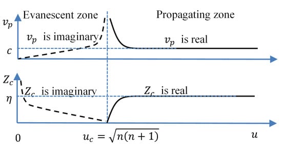
Figure 2.
Typical characteristic impedance and phase velocity of mode.
We can summarize from Figure 2 that:
- (i)
- For , the characteristic impedance approaches , and the phase velocity approaches the light velocity c.
- (ii)
- For , the characteristic impedance and the phase velocity are all real. It is an ordinary transmission line. The voltage and current signals will propagate on the line. However, the line is not a uniform transmission line (UTL) but an NTL. Generally, an NTL can be approximately considered as a section-wise-uniform transmission line, i.e., cascaded by short UTL sections with different characteristic impedances. Therefore, local reflections inevitably occur [24,25].
- (iii)
- For , the characteristic impedance and the phase velocity are all imaginary, as can be seen from (23) and (24). We can treat it as a nonuniform transmission line with negative inductance and positive capacitance. For a transmission line with a constant negative inductance and a constant positive capacitance, the general solution of (21) in this situation is , is a real number. The voltage and current on the line are evanescent. They will not propagate like waves but decay exponentially. This is similar to the case that has been widely analyzed in handling left-handed materials or left-handed transmission lines [26,27] when there is a negative permittivity or a negative permeability. The transmission line has similar behavior when the negative inductance and positive capacitance are position-dependent.
It is obvious that represents the critical state between the propagating and the evanescent state. We can consider the space between and as a two-port radial waveguide. Therefore, it is natural to introduce a cutoff spatial phase shift as
It can be observed that is a propagating mode for and an evanescent mode for .
Since , at a given frequency with specified wavenumber k, we can accordingly define a cutoff radius associated with a cutoff sphere. The mode is an evanescent one inside the cutoff sphere and becomes a propagating one outside the cutoff sphere. We can then write the propagation condition as
On the other hand, for an arbitrarily specified concentric sphere with radius r, is a propagating mode outside the sphere if its degree n satisfies . Otherwise, it remains to be an evanescent mode until it reaches a larger sphere that meets the propagation condition. Therefore, for a sphere with radius r, we can define a cutoff mode degree for mode, which is the largest integer satisfies,
Solving (27) gives
We may take the largest integer smaller than the right-hand side of (28) as the cutoff mode degree. The mode becomes a propagation mode outside the sphere if . Note that for large , .
Based on these observations, we can develop the equivalent NTL model for , as shown in Figure 3. In general situations, the NTL consists of two parts divided by the cutoff phase shift . The end port is perfectly matched with . Intuitively, the mode fields enter the input port , travel through an evanescent zone from to , pass the cutoff line, then enter the propagating zone, and propagate from to . In the evanescent zone, the fields decay approximately exponentially. In the propagating zone, the fields may also decrease much faster than at the region near to because of strong local reflections. Only when u is much larger than , the fields begin to propagate like a spherical wave with amplitude decreasing approximately in the order of .
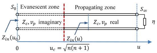
Figure 3.
NTL model for mode.
The parameters of mode with , and 25 are plotted in Figure 4, where the cutoff phase shift are respectively 5.48, 15.49, and 25.495. It can be seen that, at a fixed input port , the mode with larger n may experience longer evanescent zone and suffer from larger attenuation. It is required to excite larger fields at to send the same amount of radiation power to . In other words, it is generally less efficient to excite modes with larger degrees.
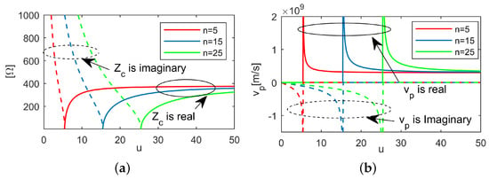
Figure 4.
Parameters for mode. . (a) Characteristic impedance. (b) Phase velocity.
In order to efficiently excite a mode, we may choose so that the evanescent zone and the high local reflection zone are excluded in the propagating path of that mode, and, intuitively speaking, we may put to the right side of the red line in Figure 3.
2.2. TE Mode
The NTL model for modes can be developed similarly. Starting from (4) and (5), and dropping the constant , we can write
in which has been applied. Define the equivalent voltage and current for as
It can be verified that the transmission power can be calculated with
Making use of (12), the telegrapher’s equation for mode is derived to be
Accordingly, the equivalent distribution inductance and distribution capacitance are
Note that the distribution capacitance varies with r, while the distribution inductance is constant, which is different from that for mode.
The local characteristic impedance for mode is defined by
It is slightly different from that of the mode expressed by (23).
The curves of the characteristic impedance of mode for and are plotted in Figure 5. Note that at the cutoff point the characteristic impedance of the mode is zero, while it is infinite for mode.
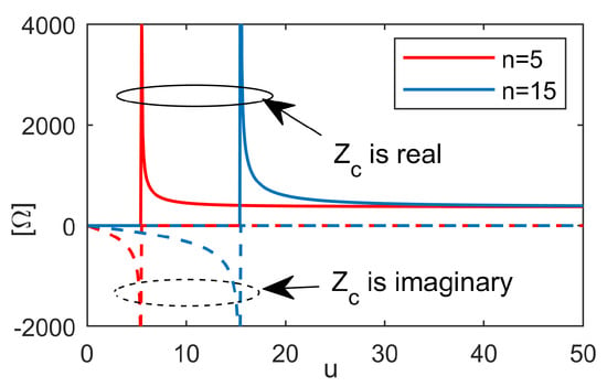
Figure 5.
Characteristic impedance of mode for and 15.
The local phase velocity of has the same expression as that of the mode, as do the cutoff phase shift , the cutoff radius , and the cut off mode degree .
3. Discussion
3.1. Generalized Input Impedance
For mode, the generalized input impedance at the sphere with radius r, , is found to be
It can be readily checked that the normalized impedance (9) defined by Chu [12] is exactly the special case of (37) at the input port for the mode.
For a mode with fixed amplitude of at , it will transfer larger radiation power with larger . is actually the radiation resistance of mode and can be used to predict the radiation capability of that mode. Larger means stronger radiation capability.
The generalized input impedance of mode for , and 25 are plotted in Figure 6, where the dashed lines indicate the cutoff phase shift for the corresponding mode. As shown in Figure 6a, the input resistances decrease rapidly with when , which clearly reveals that the radiation of a mode is weak in this region. On the other hand, a mode has a very large negative reactance in the evanescent region, which means that it is capacitive and electric energy may be stored in that region.
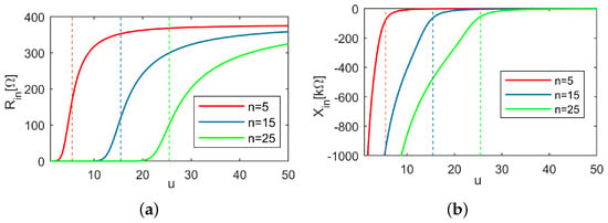
Figure 6.
Generalized input impedance of mode for , and 25. (a) Real part. (b) Imaginary part.
The normalized input impedance of the mode is
which is exactly the same expression used by Chu to develop the equivalent circuit model. Therefore, if necessary, the type of Chu’s equivalent circuit model can be developed for all modes at any spheres between and .
With the strategy used by Chu, the normalized impedance of the mode can be further cast into
It is equivalent to a series circuit consisting of a capacitor and another impedance , as shown in Figure 7, in which
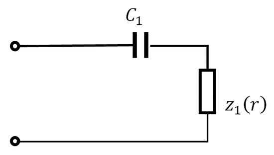
Figure 7.
A simplified equivalent circuit for mode.
The simplified equivalent circuit model also shows the capacitive nature of the input impedance of a mode. Higher degree mode has smaller capacitance and reveals stronger obstruction for radiation power to transfer.
For modes, the generalized input admittance at point r is defined as
and Chu’s normalized admittance for is just the special case at the input port .
With the same method as handling the mode, the normalized input admittance of the mode can be separated into two parts,
where
It can be described with an equivalent shunt circuit consisting of an inductor and another admittance , as shown in Figure 8.
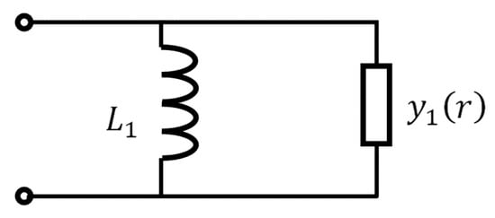
Figure 8.
A simplified equivalent circuit for mode.
The simplified equivalent circuit model shows the inductive nature of the input impedance of a mode.
3.2. Generalized Reflection Coefficient
It is reasonable to take the intrinsic impedance as the reference impedance to define a generalized reflection coefficient at r,
where is the generalized input impedance of a spherical wave mode.
The generalized reflection coefficients of the mode for , and 25 are plotted in Figure 9, The reflection coefficients are very large in the evanescent regions. Most of the electromagnetic power carried by the mode will be reflected, so the radiation efficiency tends to be very low.
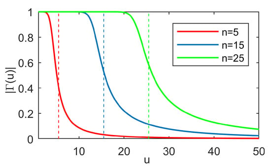
Figure 9.
Generalized reflection coefficient of mode for , and 25.
3.3. Hertzian Dipole
A Hertzian dipole generates mode field in the free space. We can check that the equivalent voltage and current on the NTL can be respectively expressed by
The cutoff radius of mode is . The shadow area in Figure 10 shows the evanescent region of the mode. The fields of the Hertzian dipole in this area will decay exponentially. As is well known, the Hertzian dipole is not an efficient radiator.
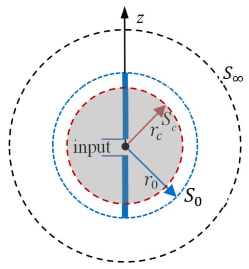
Figure 10.
The electromagnetic radiation of a dipole. Shadow: evanescent region for .
Intuitively, we have two basic methods to improve the radiation efficiency. The first one is to efficiently guide the electromagnetic power outside the cutoff region using some kind of metal structure. A typical structure is the half wavelength dipole shown in Figure 10. Its end reaches with , which is apparently locating in the propagating region of the mode. Because of the two metal arms of the dipole, spherical TEM mode can exist within . The transmission of the spherical TEM mode can be modeled using a UTL with cutoff radius of [23], corresponding to the spherical mode with degree of . It has the potential to efficiently transfer electromagnetic power from the feeding point to . Biconical antennas are also a kind of well-used structures for this purpose.
The second method is to fill the region surrounding the feeding source with some kind of dielectrics. For a dielectric with relative permittivity of , the cutoff radius of all spherical modes will decrease by a factor of . The radiation efficiency may be improved due to the shrinking of the evanescent region.
A key issue here is that additional reflection may occur on the boundary between the two regions. On a spherical surface between two uniform dielectric layers, as will be encountered in the second method, the spherical modes in the two regions still remain the same orthogonality, so the reflection occurs within each mode and can be handled mode by mode independently. However, in the first method, like using biconical antennas, the set of eigenmodes in the two regions are different. The local reflection is much complex, causing energy redistribution among the spherical modes in the outer region in free space. In both cases, the radiation efficiency may be further improved if we can introduce some kind of matching techniques on the interface.
4. Conclusions
The proposed NTL model for electromagnetic radiation of sources in a bounded region can provide an intuitive way for illustrating the propagation process of mode fields. As the NTL model is independent on the order m of the spherical modes, and share the same NTL with and , respectively.
By introducing the cutoff spatial phase shift , the traveling path of a spherical mode can be divided into an evanescent zone and a propagating zone. Although the amplitudes of the mode fields will decay in both regions, the mechanism and behaviors in the two regions are quite different.
The NTL model does not provide information about how the feeding source distributes its electromagnetic power to each spherical mode. However, it can help us to predict which modes can effectively penetrate the barrier in the near region and propagate to the far region.
The developed NTL model is valid for uniform lossless media outside the source area. A related issue is the behavior of the electromagnetic energy in the radiation process [3], which is still an important problem need to be addressed. In our future work, we will investigate the possibility of interpreting the spatial resonance behavior of the electromagnetic energy with the NTL model as can be seen that local reflections of mode fields exist even in the vacuum. Furthermore, we will try to extend the NTL model to radially nonuniform media, based on which we will design efficient guiding structures for radiation power to pass through the near zone barrier and investigate possible matching techniques between regions with different structures or materials.
Author Contributions
Conceptualization, methodology, original draft, funding acquisition, calculation, G.X. Verification, review, and editing, M.H. All authors have read and agreed to the published version of the manuscript.
Funding
This research was funded by the National Key R&D Program of China, China (Grant No. 2019YFB2204703), the National Natural Science Foundation of China, China (Grant No. 61831016), the National Natural Science Foundation of China, China (Grant No. 62188102).
Data Availability Statement
Not applicable.
Conflicts of Interest
The authors declare that the research was conducted in the absence of any commercial or financial relationships that could be construed as a potential conflicts of interest.
References
- Collin, R.; Rothschild, S. Evaluation of antenna Q. IEEE Trans. Antennas Propag. 1964, 12, 23–27. [Google Scholar]
- Vandenbosch, G.A.E. Reactive Energies, Impedance, and Q Factor of Radiating Structures. IEEE Trans. Antennas Propag. 2010, 58, 1112–1127. [Google Scholar] [CrossRef]
- Xiao, G. A theory for electromagnetic radiation and coupling. TechRxiv 2021. [CrossRef]
- Wacker, P. Unified theory of near-field analysis and measurement: Scattering and inverse scattering. IEEE Trans. Antennas Propag. 1981, 29, 342–351. [Google Scholar] [CrossRef]
- Gemmer, T.M.; Heberling, D. Accurate and Efficient Computation of Antenna Measurements via Spherical Wave Expansion. IEEE Trans. Antennas Propag. 2020, 68, 8266–8269. [Google Scholar] [CrossRef]
- Knapp, J.; Eibert, T.F. Explicit Conversion Formulas between Spherical Wave Expansions with Scalar and Vector Expansion Coefficients. IEEE Trans. Antennas Propag. 2023, 71, 752–762. [Google Scholar] [CrossRef]
- Mie, G. Contributions to the optics of turbid media, particularly of colloidal metal solutions. Contrib. Opt. Turbid. Media 1976, 25, 377–445. [Google Scholar]
- Goni, O.; Okhmatovski, V.I. Exact Solution of New Magnetic Current Based Surface-Volume-Surface EFIE and Analysis of Its Spectral Properties. IEEE J. Multiscale Multiphys. Comput. Tech. 2022, 7, 102–116. [Google Scholar] [CrossRef]
- Waterman, P. The T-matrix revisited. JOSA A 2007, 24, 2257–2267. [Google Scholar] [CrossRef] [PubMed]
- Ström, S. T matrix for electromagnetic scattering from an arbitrary number of scatterers with continuously varying electromagnetic properties. Phys. Rev. D 1974, 10, 2685. [Google Scholar] [CrossRef]
- Rubio, J.; Gonzalez, M.; Zapata, J. Generalized-scattering-matrix analysis of a class of finite arrays of coupled antennas by using 3-D FEM and spherical mode expansion. IEEE Trans. Antennas Propag. 2005, 53, 1133–1144. [Google Scholar] [CrossRef]
- Chu, L.J. Physical limitations of omni-directional antennas. J. Appl. Phys. 1948, 19, 1163–1175. [Google Scholar] [CrossRef]
- Hansen, W. A new type of expansion in radiation problems. Phys. Rev. 1935, 47, 139. [Google Scholar] [CrossRef]
- Stratton, J. Electromagnetic Theory; John Wiley & Sons, Inc.: Hoboken, NJ, USA, 1941. [Google Scholar]
- Papas, C.H. Theory of Electromagnetic Wave Propagation; Courier Corporation: New York, NY, USA, 1988. [Google Scholar]
- Sarkar, D.; Halas, N. General vector basis function solution of Maxwell’s equations. Phys. Rev. E 1997, 56, 1102. [Google Scholar] [CrossRef]
- Ludwig, A. Near-field far-field transformations using spherical-wave expansions. IEEE Trans. Antennas Propag. 1971, 19, 214–220. [Google Scholar] [CrossRef]
- Collin, R.E. Field Theory of Guided Waves; John Wiley & Sons: Hoboken, NJ, USA, 1990; Volume 5. [Google Scholar]
- Abramowitz, M.; Stegun, I. Handbook of Mathematical Functions; Ninth Corrected Printing; National Bureau of Standards: Washington, DC, USA, 1970. [Google Scholar]
- Devaney, A.J. Mathematical Foundations of Imaging, Tomography and Wavefield Inversion; Cambridge University Press: New York, NY, USA, 2012. [Google Scholar]
- Jensen, F.; Frandsen, A. On the number of modes in spherical wave expansions. In Proceedings of the 26th AMTA, Stone Mountain, GA, USA, 17–22 October 2004; Volume 2, pp. 489–494. [Google Scholar]
- Gumerov, N.A.; Duraiswami, R. Fast Multipole Methods for the Helmholtz Equation in Three Dimensions; Elsevier: Amsterdam, The Netherlands, 2005. [Google Scholar]
- Kong, J. Electromagnetic Wave Theory; EMW Publishing: Cambridge, MA, USA, 2008. [Google Scholar]
- Xiao, G.; Yashiro, K.; Ohkawa, S. A new numerical method for synthesis of arbitrarily terminated lossless nonuniform transmission lines. IEEE Trans. Microw. Theory Tech. 2001, 49, 369–376. [Google Scholar] [CrossRef]
- Miano, G.; Maffucci, A. Transmission Lines and Lumped Circuits; Academic Press: San Diego, CA, USA, 2001. [Google Scholar]
- Alù, A.; Engheta, N.; Erentok, A.; Ziolkowski, R.W. Single-negative, double-negative, and low-index metamaterials and their electromagnetic applications. IEEE Antennas Propag. Mag. 2007, 49, 23–36. [Google Scholar] [CrossRef]
- Lai, A.; Itoh, T.; Caloz, C. Composite right/left-handed transmission line metamaterials. IEEE Microw. Mag. 2004, 5, 34–50. [Google Scholar] [CrossRef]
Disclaimer/Publisher’s Note: The statements, opinions and data contained in all publications are solely those of the individual author(s) and contributor(s) and not of MDPI and/or the editor(s). MDPI and/or the editor(s) disclaim responsibility for any injury to people or property resulting from any ideas, methods, instructions or products referred to in the content. |
© 2023 by the authors. Licensee MDPI, Basel, Switzerland. This article is an open access article distributed under the terms and conditions of the Creative Commons Attribution (CC BY) license (https://creativecommons.org/licenses/by/4.0/).