Abstract
In order to improve the accuracy of multi-projection correction fusion, a multi-projection correction method based on binocular vision is proposed. To date, most of the existing methods are based on the single-camera mode, which may lose the depth information of the display wall and may not accurately obtain the details of the geometric structure of the display wall. The proposed method uses the depth information of a binocular camera to build a high-precision 3D display wall model; thus, there is no need to know the specific CAD size of the display wall in advance. Meanwhile, this method can be applied to display walls of any shape. By calibrating the binocular vision camera, the radial and eccentric aberration of the camera can be reduced. The projector projects the encoded structured light stripes, and the high-precision 3D structural information of the projection screen can be reconstructed according to the phase relationship after collecting the deformation stripes on the projection screen with the binocular camera. Thus, the screen-projector sub-pixel-level mapping relationship is established, and a high-precision geometric correction is achieved. In addition, by means of the one-to-one mapping relation between the phase information and the three-dimensional space points, accurate point cloud matching among multiple binocular phase sets could be established, so that such method can be applied to any quantity of projectors. The experimental results based on various special-shaped projection screens show that, comparing to the single-camera-based method, the proposed method improves the geometric correction accuracy of multi-projection stitching by more than 20%. This method also has many advantages, such as strong universality, high measurement accuracy, and rapid measurement speed, which indicate its wide application potential in many different fields.
1. Introduction
With the rapid development of computer vision technology and large-screen display technology, multi-projection correction fusion system [1,2,3,4,5], with its advantages of high resolution, strong immersion and large screen size, is widely used in scientific computing visualization, military simulation, opening and closing ceremonies of comprehensive sports games, business and entertainment, etc. It meets people’s display needs for strong realism, immersion, and real-time drawing, among others.
In order to obtain an image without distortion on a display wall, it is necessary to pre-distort the output picture of the projector to offset the geometric distortion caused by the display wall. Therefore, the key to geometric correction is to establish an accurate geometric mapping relation between the projector and the display wall. According to different correction methods, geometric correction could be divided into manual correction and camera-based correction. In manual correction, a base with multiple degrees of freedom adjustment is installed beneath a projector. The image projected by the projector could be stitched by adjusting each freedom adjustment, according to the literature [6], which creates high demands for an operator’s professional skills. In addition to the manual correction mode, the automatic correction mode based on a camera is more extensively applied, in which the main principle is to collect the feature image projected by a projector and establish the mapping relation between the projector and the display wall by means of decoding. For instance, ref. [7] introduced a method in which cameras were first geometrically calibrated, and then the characteristic lattice projected by each projector was shot. Subsequent to feature recognition, the homography mapping matrix between the display wall and the projector was calculated, and the image was pre-distorted by this matrix. Ref. [8] established the mapping relation between a projector’s coordinate system and a camera’s coordinate system by virtue of binary-coded structured light feature images, after which the image was reconstructed through reverse mapping. Such an algorithm does not require accurate calibration of the projector and the camera, nor does it need to know the surface equation of the display wall. However, it could only be applied in a scenario where the shooting range of the camera can fully cover the projection range of the projector, which limits its application in large-scale display systems. Ref. [9] evaluated the correction errors caused by the distortion of cameras and projectors, developed a self-adaptive geometric correction algorithm based on a closed-form model, and showed the experimental results on a flat display wall. Ref. [10] summarized several automatic correction algorithms based on cameras, compared the advantages and disadvantages of various kinds of algorithms, and pointed out the direction for subsequent research development.
Additionally, in order to deal with the deformation caused by a display wall, ref. [11] assumed that a projector is a pinhole model and used a two-step correction method to pre-deform the image, i.e., first rendering a 3D scene and then projecting the rendered image onto a curved display wall through the method of projecting texture. Ref. [12] used the reverse-stripe projection technology to establish the mapping relationship between a projector and a display wall, but this technique cannot be extended to large-scale panoramic display systems. In 2019, Zhao et al. [13] theoretically demonstrated the principle of geometric correction for multi-projection systems and proposed the consistency principle of geometric correction, i.e., the geometric error is only related to the structural parameters of the multi-projection system. A new geometric calibration method based on red-blue-gray encoded structured light was proposed for the alignment of multi-projectors on parametric surfaces using binocular vision techniques. In the same year, Portales et al. [14] proposed a method to calibrate a projector quickly when the projector was at a high location (3 m above the ground) by identifying six control points on a cylindrical surface, establishing a direct linear transform (DLT) mathematical model, solving 11 parameters, and obtaining the correspondence between the camera and the 3D spatial points. Wang et al. [15] used a Bessel surface model to establish a generalized geometric transformation function to obtain the corresponding relation matrix between the coordinates of a projector’s image spatial points and a display’s surface spatial points; they stitched the projector’s Bessel surface, assigned the projection task, and calculated the pre-distortion matrix of each projector. In 2020, Jianchao Liu et al. [16] used a Bessel surface model to obtain the transformation relationship between the projection screen surface and the projector image space; they established a coordinate system according to the pilot position and the cylindrical surface, obtained the transformation between the image coordinates of the projector and the image coordinates of the output of the scene-rendering system, and completed the surface correction. Ref. [17] proposed a quadratic quasi-uniform B-spline with shape parameters to reconstruct a curved surface screen. In this method, the position of the control point was adjusted to fit the projection screen to the curved screen so as to eliminate the geometric distortion caused by the non-planar screen and ensure the control grids of the merged regions of adjacent channels roughly coincide. Then, the shape parameters were adjusted so that the control area of the fusion area could reach the pixel-level coincidence. In order to solve the problem of low geometric correction accuracy of a multi-channel projection cavern automatic virtual system, ref. [18] proposed a set of geometric optimizations based on a segmented Bezier surface to ensure the geometric correction accuracy of the same channel projection image. The optimization of geometric correction was performed through the matrix block, perspective transformation, screen space transformation, and segmented Bezier surface. The main defect of the above two methods was that they needed to know the accurate geometric structure information of the display wall, which limited their popularization and applications.
However, existing multi-projection stitching fusion methods mainly use a single camera for feature image acquisition, and the images acquired by a single camera cannot be accurately adapted to projection screens of different shapes due to the loss of spatial depth information, which in turn affects the accuracy of calibration fusion. Ref. [19] used Azure Kinect to collect the color information and depth information of an irregular projection surface, obtained the largest visible projection area from the color image, and calculated the target projection position according to the ratio of the projection area. The homography matrix was obtained by solving each depth layered plane, and a set of homography matrices was constructed to correct the geometric distortion of the projection image. However, this method depends on the particular equipment, so it is not a universal method.
This problem can be better solved by using binocular stereo vision cameras, which mainly apply the triangulation principle. For the same object in space, there is deviation in imaging due to the position deviation between two cameras. Through camera calibration [20] and the polar constraint relationship, the correspondence between two cameras can be established, and the pixel coordinate positions of the object to be measured in the two cameras can be obtained through the acquired coded images. Then, the 3D spatial coordinates of the object can be obtained according to the triangulation principle, thus realizing the 3D reconstruction of space. In addition, by means of the one-to-one mapping relation between the phase information and the three-dimensional space points, the accurate point cloud matching among multiple binocular phase sets could be established; therefore, such a method can be applicable for any quantity of projectors.
Based on this method, this paper introduces the measurement principle of binocular stereo vision into a multi-projection correction technology and uses its spatial depth information to build an accurate three-dimensional display wall structure. The proposed method improves the geometric correction accuracy of multi-projection stitching by more than 20%, when compared to an existing method, and it has the advantages of strong universality, high measurement accuracy, and rapid measurement speed. This paper presents the results of the derivation of its related principles and application in research, analyzes the advantages and disadvantages of binocular stereo vision in the application of multi-projection correction, and points out the direction for future development in this field.
2. Materials and Methods
The multi-projection correction technology based on binocular stereo vision mainly includes the projection and acquisition of structured light feature images, binocular vision reconstruction, point cloud alignment, latitude and longitude mapping, and geometric correction data generation, among others. The implementation flow of this method is shown in Figure 1.
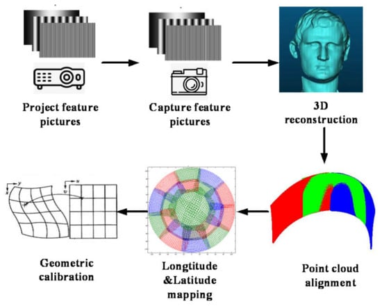
Figure 1.
Algorithm flow chart.
The left and right cameras constitute a binocular stereo vision system. A projector is introduced to project phase-shifting coded-stripe structured light onto the object surface, which is equivalent to projecting a group of monotonically changing phases [21,22,23]. The left and right cameras synchronously collect the fringe patterns modulated by the object. According to the PMP [24,25,26] measurement principle, the phase images of the left and right cameras can be obtained. The point with the same phase value in the left camera and the right camera is the matching point, which can be obtained by searching the polar line; finally, the parallax map of the object will be obtained. The schematic diagram of structured light binocular vision measurement is shown in Figure 2.
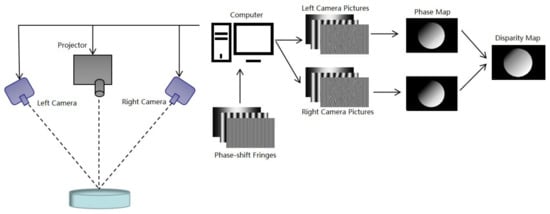
Figure 2.
Structured light binocular vision measurement diagram.
2.1. Process of the Stitching
The essence of geometric correction is to achieve the stitching of adjacent projectors and the deformation correction of the shaped projection screens. Here, dual-channel projection stitching is taken as an example to illustrate the principle of the algorithm, as shown in Figure 3.
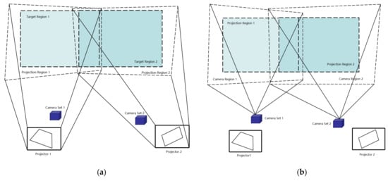
Figure 3.
Dual-channel projector and binocular camera projection and shooting area: (a) projector projection area, and (b) binocular camera shooting area.
The specific algorithm steps are as follows:
- Projector 1 is referred to as P1; projector 2 is referred to as P2; binocular camera 1 is referred to as C1; and binocular camera 2 is referred to as C2. Projectors P1 and P2 are used to project horizontal and vertical phase-shifted structured light-encoded images onto the screen, and then binocular cameras C1 and C2 are used to acquire the stripe images of each group. One set of camera coordinate systems is set as the unified coordinate system of the point cloud image; the other corresponding projector is used to project the stripe map, and the cameras of this group acquire the images simultaneously.
- The three-dimensional reconstruction of the projection screen is performed using the acquired feature images of each group, while storing the horizontal and vertical phase data corresponding to the solution of each group of data and the three-dimensional reconstruction data of the projection screen.
- The complete point cloud data of P1’s and P2’s projection screens are transferred to the set point cloud unified coordinate system using the transformation relationship to achieve complete point cloud alignment.
- The aligned point cloud images are converted from a Cartesian coordinate system to a spherical coordinate system to calculate the latitude and longitude distributions of the corresponding point cloud images of adjacent projectors, and the latitude and longitude data corresponding to the pixel points of each projector’s frame cache image are determined according to the interpolation of the horizontal and vertical phase distributions.
- Finally, the longitude and latitude data are used to calculate the perspective projection cone parameters (up, down, left, and right viewing angles, HPR deflection angles, etc.), which are used to convert the images in the frame cache into pre-deformed images and complete the geometric correction.
2.2. Binocular Vision 3D Reconstruction Method
The stripe projection method using phase coding has the advantages of high-quality measurement accuracy, fast measurement speed, high point density, and low cost. The core of binocular stereo vision lies in solving the image parallax of two cameras for the same measurement object, and then solving the object spatial coordinates according to the parallax value. By combining the binocular stereo vision method with the three-frequency, four-step, and phase-shifted structured light encoding method to complete the 3D reconstruction, the precise 3D coordinates of the target object can be obtained:
In Equation (1), I(x, y) represents the intensity distribution of the acquired deformed fringe; A(x, y) represents the intensity of the background light; B(x, y)/A(x, y) represents the modulation of stripes; and (x, y) represents the phase information, which includes the height information of the surface of the object to be measured.
In Equation (2), Z is the distance between the spatial object point and the baseline of the measuring camera; B is the baseline distance between the center of the lens of the left and right cameras; f is the principal distance of the camera lens; and xL and xR are the distances between the imaging points of a spatial point P in the image planes of the camera CL and CR, respectively. CL is defined as the left camera of the binocular phase set, and CR is defined as the right camera of the binocular phase set. The three-dimensional reconstruction process is shown in Figure 4 below.
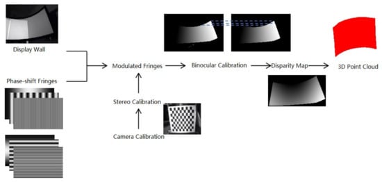
Figure 4.
Binocular vision 3D reconstruction method flow chart.
2.3. Point Cloud Alignment Method
Based on the above 3D reconstruction method, the spatial 3D coordinates of the projection surface and the corresponding horizontal and vertical phases of the left and right cameras can be solved when the binocular cameras are placed at two different positions. The core objective of point cloud alignment is to transform the spatial coordinate points of projectors P1 and P2 to the same coordinate system. The coordinate system of the left binocular camera is used as the aligned coordinate system of the point cloud. Since the transformation relationship of the two binocular cameras cannot be obtained from the outside when binocular cameras C1 and C2 are located at two different positions, the structured light feature stripe image is studied here. As shown in Figure 5, due to the overlapping area between the two adjacent projectors, when projector P1 projects horizontal and vertical structured light stripe maps, the image acquisition using binocular cameras C1 and C2 can only capture part of the image projected by projector P1, and the binocular camera C1 is able to capture the complete image projected by projector P1. In Figure 5, the red point P is an arbitrary point in the overlap region.
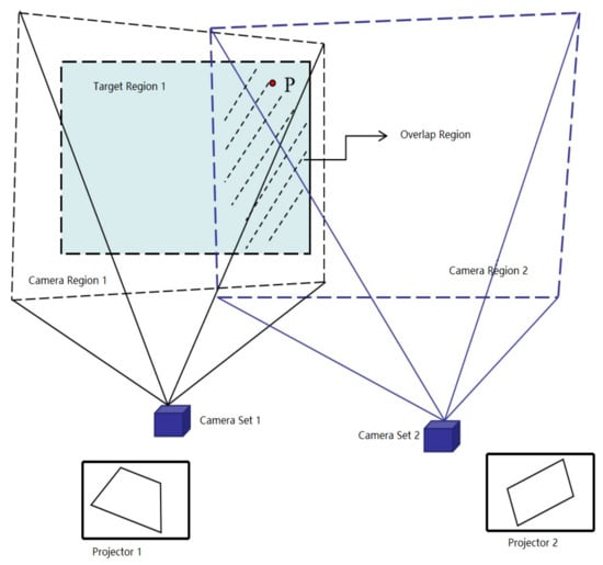
Figure 5.
Schematic diagram of projector P1’s projection and binocular cameras C1 and C2 image acquisition.
Here, the absolute phase in the horizontal and vertical directions of each group of acquired images is solved using the three-frequency, four-step phase shift method. For instance, the point P in Figure 5 projected on the screen by projector P1, the location of this point in the phase distribution diagram is shown in Figure 6.

Figure 6.
Vertical phase and horizontal phase grayscale distribution map.
The horizontal phase and the vertical phase represent two coordinate axis directions, which intersect at a unique point in the image, and the mapping relationship between the phase and the only spatial point coordinate in the three-dimensional space is established, that is, (leftI_21,leftIV_21) → (X1,Y1,Z1), (leftI_21,leftIV_21) → (X21,Y21,Z21). Then, the interpolation function can be used to find the corresponding spatial coordinate point of phase pair (leftI_21,leftIV_21) in (X1,Y1,Z1), represented by (Xtemp,Ytemp,Ztemp).
(Xtemp,Ytemp,Ztemp) and (X21,Y21,Z21) represent the point cloud coordinates of the same target object in different coordinate systems, and there are N groups of such spatial corresponding points. The relationship equation between the two is as follows.
where R is the rotation matrix and T is the translation variable, these two parameters represent the position relationship of the points in 3D space. [X21,Y21,Z21,1]T and [Xtemp,Ytemp,Ztemp,1]T are both 4 × N matrices. The (X21,Y21,Z21) can be converted to the (X22,Y22,Z22) coordinate system using R and T parameters to complete the point cloud alignment.
2.4. Point Cloud Alignment Method
Latitude and longitude constitute a geographic coordinate system; here, latitude and longitude are used in the sphere mapping, as shown in Figure 7.
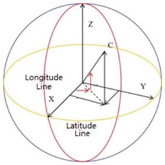
Figure 7.
Spherical definition diagram of latitude and longitude.
If the coordinates of a point on the sphere are (x, y, z) and the radius of the sphere is R, then the following formula can be used to solve for the value of its corresponding latitude and longitude, which are denoted as Lo for longitude and La for latitude.
Given the spatial coordinate points of projector P1: (X1p,Y1p,Z1p) and projector P2: (X22,Y22,Z22), they can be transferred from Cartesian coordinates to a spherical coordinate system to obtain the latitude and longitude values of each point. However, it is necessary to obtain the longitude and latitude values corresponding to each projector pixel, so that the image projected by the projector can achieve geometric registration.
Take projector P1: (X1p,Y1p,Z1p) as an example, its latitude and longitude values are denoted as (Lo1,La1). According to the correspondence (leftI_1,leftIV_1) → (Lo1,La1), the projector projects a phase-shifted stripe map, and the phase value (leftI,leftIV) of the pixel points at each position of the projector is known. A set of corresponding values (leftI_1,leftIV_1) → Lo1 are surface fitted and brought in (leftI,leftIV) to obtain the latitude and longitude values corresponding to each projector pixel point. Similarly, projector P2: (X22,Y22,Z22) obtains the latitude and longitude values corresponding to the cached pixels of each frame in the projectors of the two channels.
According to the obtained projection latitude and longitude, the perspective projection cone parameters are determined, and the longitude and latitude data corresponding to each pixel of the frame cache image are converted to texture coordinates using the cone parameters to generate a pre-deformed image, which is projected by a projector to complete the geometric correction of the two large channel projectors.
3. Results
In order to verify the effectiveness and feasibility of the algorithm proposed in this paper, several experiments are designed. The procedure of geometric correction based on binocular vision is presented below in Figure 8.
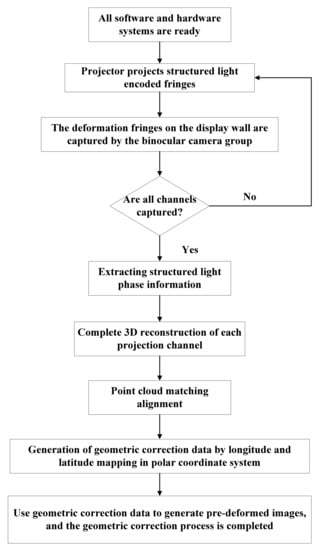
Figure 8.
Procedure of geometric correction based on binocular vision.
The first projection environment shown in Figure 9 is used, which is a capsule-like shaped screen. Fourteen projectors are divided into the upper and lower layers for projection splicing.
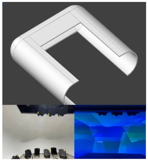
Figure 9.
Projection environment of capsule-like curtain.
The three mainframes are connected via a LAN, and each mainframe is connected to a projector. In addition, there are binocular cameras, calibration boards, and other hardware devices. The camera is an industrial camera MGS230M-H2 of Dusen Technology, and the calibration board model is GP800-12×9. The binocular camera set is shown in Figure 10.
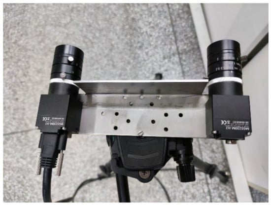
Figure 10.
Binocular camera set.
3.1. Binocular Camera Calibration
In this paper, Zhang Zhengyou’s planar template calibration algorithm is used to calibrate the binocular camera group. Sixteen calibration images of a tessellated grid with different orientations and angles are acquired by the left and right cameras simultaneously, and then the process calibration is performed by using the Matlab calibration toolbox to obtain the internal parameters of the left and right cameras. Finally, stereo calibration is performed to obtain the relative position relationship between the binocular cameras, and the calibration results are shown in Table 1.

Table 1.
Binocular camera calibration results.
In Table 1, the second column is the intrinsic parameters obtained from the camera calibration. Specifically, fc is the focal length, which is the distance between the optical center of the camera and the principal point. cc is the principal point coordinate, which is the intersection of the camera optical axis and the image plane. alpha_c is the skew coefficient, which defines the angle between x and y pixel axes. kc is the image distortion coefficient.
3.2. Stitching of Cylindrical Projection Screen
After the calibration of the binocular camera group was completed, the three-frequency method (stripe periods of 1, 8 and 64) is used to project the structured light feature stripe images in two directions (vertical and horizontal) based on a four-step phase shift for a total of 24 images, and some of the projected images are shown in Figure 11.
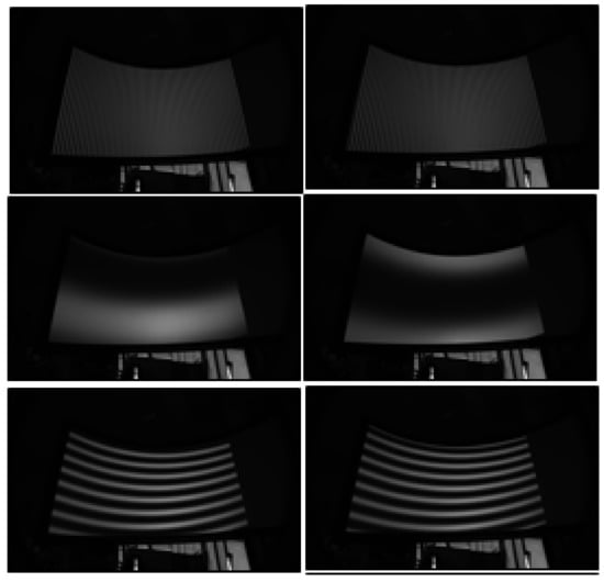
Figure 11.
Partially captured feature stripe map.
The horizontal and vertical absolute phase grayscale distribution of the left camera and the horizontal absolute phase grayscale distribution of the right camera are calculated based on the acquired stripe images, and the horizontal phase grayscale maps of the left and right cameras are corrected using the polar line.
The principle of binocular stereo vision is used to reconstruct the surface of the projection screen in three dimensions, and the Figure 12 shows the reconstructed image of the point cloud calculated by the left camera of camera groups C1 and C2, respectively, when projector P1 is specified to project. Since camera C2 is placed in the middle position, only part of the image of the projector can be seen, and, thus, the point cloud is only partially reconstructed.

Figure 12.
Three-dimensional point cloud map of the projector’s projection area. (a) P1 projection, with C1 acquisition, and (b) P1 projection, with C2 acquisition.
The point cloud data of the different channels are stereo matched to generate the complete point cloud data of the coordinate system. Figure 13 shows the schematic effect of the point cloud data matching to the three channels. The point cloud data of the different projection channels are marked with different colors.
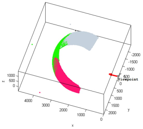
Figure 13.
Point cloud matching diagram of the binocular camera.
The whole point cloud aligned image is converted from a right-angle coordinate system to a spherical coordinate system, and the longitude and latitude distribution of each projector is obtained using phase interpolation. Finally, the longitude and latitude data are converted to texture coordinates using the cone parameters to generate pre-deformed images, i.e., the geometric correction is completed.
3.3. Results of the Stitching
A projection grid is used for stitching to show the line overlapping between the channels. Figure 14 shows the comparative effect of the method proposed in this paper and the method proposed in [13]. From the overall point of view, the stitching effect of both methods is acceptable; however, in detail, the method of this paper is better in terms of regular lines in the overlapping area and a lack of cross-open seams. The reason is that the shape of the projection surface of the capsule-shaped screen is more complex, and the stitching is more difficult.
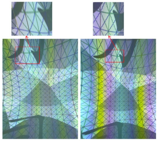
Figure 14.
Comparison of projection stitching effect.
A dome-type projection environment is shown in Figure 15, with a total of 24 projectors projecting on three levels from the top to the bottom.
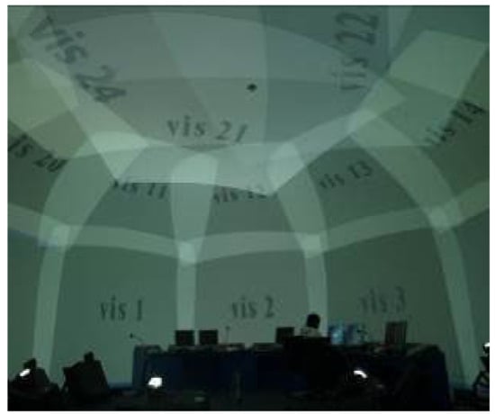
Figure 15.
Dome-type screen projection environment.
The results of the comparison between the method proposed in this paper and the method proposed in [13] are shown in Figure 16.
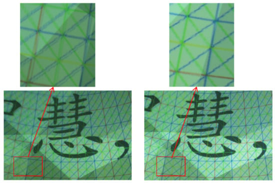
Figure 16.
Fourteen-grid stitching effect of the algorithm in [13] and the method proposed in this paper (the right image is based on the method proposed in this paper).
Figure 17 and Figure 18 show the contrast in the image effects on a display wall before and after geometric correction. It can be seen that the method proposed in this paper is feasible.
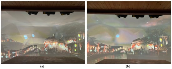
Figure 17.
Contrast in a capsule-type projection system: (a) before geometric correction and (b) after geometric correction.
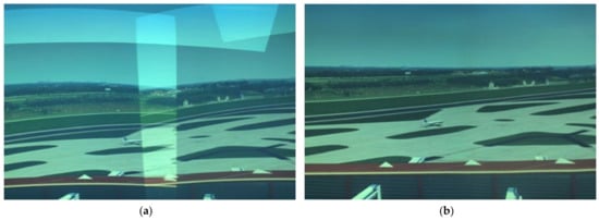
Figure 18.
Contrast in a multi-projector system: (a) before geometric correction, and (b) after geometric correction.
4. Discussion
In order to quantitatively describe geometric stitching accuracy, the overlapping thickness of the latitude and longitude lines in the overlapping region is used as a quantitative index to evaluate the geometric correction accuracy. The performance comparison of two different algorithms under two different projection environments is presented in Table 2.

Table 2.
Algorithm performance comparison table.
It should be noted that the standard width of the latitude and longitude lines in Table 2 is based on the average width of the latitude and longitude lines in the non-fused area; the maximum error is the maximum width of the latitude and longitude lines minus the standard width; and the average error is the average of all errors. A total of 20 test areas were selected in the experiment. From the data results, it can be seen that the proposed method in this paper can improve the geometric correction accuracy by more than 20% in the case of more complex projection display wall when compared to a previous method, which reflects the advantages of the structured light measurement technology under binocular vision.
5. Conclusions
This paper investigates a multi-projection stitching correction method based on binocular stereo vision. By calibrating the binocular camera group, the binocular relationship is established. Then, the 3D stereo coordinates of the projection screen can be reconstructed through the projection acquisition of structured light feature stripe maps, and the sub-pixel-level mapping relationship between the projector and the projection screen can be constructed to generate high-precision geometric correction data. The experiment was carried out through a three-channel cylindrical screen. The experimental results show that the proposed method can greatly improve the accuracy of geometric correction and has a high degree of automation, with no restrictions on the shape of the projection screen. It can be promoted and applied in application fields that have demands for large-scale projection, such as cultural entertainment, military simulation, VR/XR, and civil aviation air traffic control simulation.
Author Contributions
Conceptualization, S.W. and Z.Y.; methodology, S.W.; software, Y.Z.; validation, S.W. and Y.Z.; formal analysis, S.W.; investigation, S.W.; resources, S.W.; writing—original draft preparation, S.W.; writing—review and editing, Y.Z. All authors have read and agreed to the published version of the manuscript.
Funding
This research was funded by the Sichuan Provincial Department of Science and Technology Applied Basic Research Project, grant number 2021YJ0079.
Data Availability Statement
Data are available on request due to restrictions, e.g., privacy and ethical reasons.
Acknowledgments
We thank the anonymous reviewers for their detailed reviews and insightful comments that have helped to improve this article substantially. The funding support for our work is greatly appreciated.
Conflicts of Interest
The authors declare no conflict of interest.
References
- Sajadi, B.; Majumder, A. Autocalibration of Multiprojector CAVE-Like Immersive Environments. IEEE Trans. Vis. Comput. Graph. 2011, 18, 381–393. [Google Scholar] [CrossRef] [PubMed]
- Juang, R.; Majumder, A. Photometric Self-calibration of a Projector-camera System. In Proceedings of the IEEE Conference on Computer Vision and Pattern Recognition, Minneapolis, MN, USA, 17–22 June 2007; pp. 1–8. [Google Scholar]
- Sajadi, B.; Lazarov, M.; Gopi, M.; Majumder, A. Color Seamlessness in Multi-Projector Displays Using Constrained Gamut Morphing. IEEE Trans. Vis. Comput. Graph. 2009, 15, 1317–1326. [Google Scholar] [CrossRef] [PubMed]
- Liu, S.; Ruan, Q.; Li, X. The Color Calibration across Multi-Projector Display. J. Signal Inf. Process. 2011, 12, 53–58. [Google Scholar] [CrossRef]
- Sajadi, B.; Majumder, A. Autocalibrating Tiled Projectors on Piecewise Smooth Vertically Extruded Surfaces. IEEE Trans. Vis. Comput. Graph. 2011, 17, 1209–1222. [Google Scholar] [CrossRef] [PubMed]
- Clodfelter, R.M.; Nir, Y. Multichannel display systems for data interpretation and command and control. Cockpit Disp. 2003, 5080, 250–259. [Google Scholar] [CrossRef]
- Rajeev, J. Scalable Self-calibration Display Technology for Seamless Large-scale Displays. Ph.D. Thesis, Massachusetts Institute of Technology, Cambridge, MA, USA, 1999. [Google Scholar]
- Philippe, T.J.; Sebastien, R.; Martin, T. Multi-projectors for Arbitrary Surfaces without Explicit Calibration nor Reconstruction. In Proceedings of the 4th International Conference on 3D Digital Imaging and Modeling, Banff, AB, Canada, 6–10 October 2003; pp. 217–224. [Google Scholar]
- Bhasker, E.; Juang, R.; Majumder, A. Registration Techniques for Using Imperfect and Partially Calibrated Devices in Planar Multi-Projector Displays. IEEE Trans. Vis. Comput. Graph. 2007, 13, 1368–1375. [Google Scholar] [CrossRef]
- Brown, M.; Majumder, A.; Yang, R. Camera-based calibration techniques for seamless multiprojector displays. IEEE Trans. Vis. Comput. Graph. 2005, 11, 193–206. [Google Scholar] [CrossRef]
- Liu, G.H.; Yao, Y.X. Correction of Projector Imagery on Curved Surface. Comput. Aided Eng. 2006, 15, 11–14. [Google Scholar]
- Cai, Y.Y.; Su, X.Y.; Xiang, L.Q. Geometric Alignment of Multi-projector Display System Based on the Inverse Fringe Projection. Opto-Electron. Eng. 2006, 33, 79–84. [Google Scholar]
- Zhao, S.; Zhao, M.; Dai, S. Automatic Registration of Multi-Projector Based on Coded Structured Light. Symmetry 2019, 11, 1397. [Google Scholar] [CrossRef]
- Portalés, C.; Orduña, J.M.; Morillo, P.; Gimeno, J. An efficient projector calibration method for projecting virtual reality on cylindrical surfaces. Multimed. Tools Appl. 2019, 78, 1457–1471. [Google Scholar] [CrossRef]
- Wang, X.; Yan, K.; Liu, Y. Automatic geometry calibration for multi-projector display systems with arbitrary continuous curved surfaces. IET Image Process. 2019, 13, 1050–1055. [Google Scholar] [CrossRef]
- Liu, J.C.; Lin, Y.J.; Wang, J.; Wang, W.; Kong, Q.B. Image mosaic and fusion technology of multi-channel projection based on spherical screen. Electron. Opt. Control 2020, 27, 112–115. [Google Scholar]
- Feng, C.D.; Chen, Y.J.; Xue, Y.T.; Zhang, Y.F. Geometric Correction of Multi-Channel Surface Projection Based on B-Spline. Comput. Simul. 2019, 36, 234–238. [Google Scholar]
- Song, T.; Qi, J.H.; Hou, P.G.; Li, K.; Zhao, M.Y. Geometric Optimization of Projection Image Based on Bezier Surface. J. Yanshan Univ. 2021, 45, 449–455. [Google Scholar]
- Zhang, C.; Man, X.; Han, C. Geometric Correction for Projection Image Based on Azure Kinect Depth Data. In Proceedings of the 2020 International Conference on Virtual Reality and Visualization (ICVRV), Recife, Brazil, 13–14 November 2020; pp. 196–199. [Google Scholar]
- Meng, X.; Hu, Z. A new easy camera calibration technique based on circular points. Pattern Recognit. 2003, 36, 1155–1164. [Google Scholar] [CrossRef]
- Xing, Y.; Quan, C.; Tay, C. A modified phase-coding method for absolute phase retrieval. Opt. Lasers Eng. 2016, 87, 97–102. [Google Scholar] [CrossRef]
- Cui, H.; Liao, W.; Dai, N.; Cheng, X. A flexible phase-shifting method with absolute phase marker retrieval. Measurement 2012, 45, 101–108. [Google Scholar] [CrossRef]
- Fujigaki, M.; Sakaguchi, T.; Murata, Y. Development of a compact 3D shape measurement unit using the light-source-stepping method. Opt. Lasers Eng. 2016, 85, 9–17. [Google Scholar] [CrossRef]
- Hyun, J.-S.; Zhang, S. Enhanced two-frequency phase-shifting method. Appl. Opt. 2016, 55, 4395–4401. [Google Scholar] [CrossRef]
- An, Y.; Liu, Z.; Zhang, S. Evaluation of pixel-wise geometric constraint-based phase-unwrapping method for low signal-to-noise-ratio (SNR) phase. Adv. Opt. Technol. 2016, 5, 423–432. [Google Scholar] [CrossRef]
- Zuo, C.; Huang, L.; Zhang, M.; Chen, Q.; Asundi, A. Temporal phase unwrapping algorithms for fringe projection profilometry: A comparative review. Opt. Lasers Eng. 2016, 85, 84–103. [Google Scholar] [CrossRef]
Disclaimer/Publisher’s Note: The statements, opinions and data contained in all publications are solely those of the individual author(s) and contributor(s) and not of MDPI and/or the editor(s). MDPI and/or the editor(s) disclaim responsibility for any injury to people or property resulting from any ideas, methods, instructions or products referred to in the content. |
© 2023 by the authors. Licensee MDPI, Basel, Switzerland. This article is an open access article distributed under the terms and conditions of the Creative Commons Attribution (CC BY) license (https://creativecommons.org/licenses/by/4.0/).