Article

Design and Multi-Objective Optimization of a Composite Cage Rotor Bearingless Induction Motor

1
School of Electrical and Information Engineering, Jiangsu University, Zhenjiang 212013, China
2
Automotive Engineering Research Institute, Jiangsu University, Zhenjiang 212013, China
*
Author to whom correspondence should be addressed.
Electronics 2023, 12(3), 775; https://doi.org/10.3390/electronics12030775
Submission received: 5 January 2023 / Revised: 20 January 2023 / Accepted: 21 January 2023 / Published: 3 February 2023

Abstract

:
To improve the quality of starting torque and suspension force, a composite cage rotor bearingless induction motor (CCR-BIM) is designed, which adopts a composite cage rotor structure that combines an inner rotor and an outer rotor. First, the overall structure of the CCR-BIM is designed, the composite cage rotor of the CCR-BIM is specially designed and analyzed for the induction principle, and the mathematical model of suspension force and torque is deduced. Second, the initial structural parameters are determined, and motor qualities, such as starting torque quality and suspension force quality, are compared and analyzed between the proposed motor and BIM using a finite element model (FEM). Third, based on the response surface model (RSM), a multi-objective improved NSGA-II is constructed, and the three optimization objectives of starting torque, suspension force, and suspension force pulsation are optimized. Finally, the results of the experimental setup prove that the starting torque increases by 6.98%, the suspension force increases by 5.45%, and the suspension force pulsation decreases by 18.54%. The effectiveness of the proposed motor and the correctness of the multi-objective optimization strategy are verified.

1. Introduction

The function of a motor is to realize the energy conversion between mechanical energy and electrical energy, and the motor rotation is supported by the motor shaft. The traditional shaft is not suitable for the special application field due to the friction, wear, and other defects, so the bearingless motor has become one of the research directions [1]. The bearingless motor has many advantages, such as no friction, no wear, and high reliability [2]. It can meet the special needs of high-end equipment manufacturing and has a very broad application prospect in flywheel energy storage, the aerospace industry, the precision chemical industry, and other high-speed drive equipment fields [3]. Compared with other types of bearingless motors, the bearingless induction motor (BIM) has significant advantages, such as a simple structure, a low price, convenient maintenance, etc., and has significant advantages in flywheel energy storage system applications [4]. In order to meet the requirements of flywheel energy storage systems, many scholars have carried out extensive research on the structural design of the BIM aiming at improving the torque quality and suspension quality. The influence law of the rotor slot width on the torque quality and suspension quality of the BIM was revealed. By designing the optimal notch width, not only good torque quality and suspension quality were obtained, but also the load loss of the motor was effectively reduced [5]. The optimal rotor circuits of the BIM were proposed considering a thickness of the divided coil end conductors. The optimal design point was obtained by changing the thickness, and the performance of the BIM was improved [6]. The structure of the bearingless outer rotor induction motor was designed, the key parameters of the proposed motor were optimized, and the torque ripple was effectively reduced [7]. However, the traditional design of the BIM mainly improved a certain structure or parameter of the BIM, which cannot improve the performance of the motor comprehensively. According to the requirements of repeated starting, high starting torque, and good suspension quality of flywheel energy storage systems, it is necessary to redesign the BIM comprehensively. A new composite cage rotor bearingless induction motor (CCR-BIM) is designed in this article. The stator of the CCR-BIM has two sets of windings: one is the torque winding, and the other is the suspension force winding. The rotor of the CCR-BIM adopts a composite cage rotor structure composed of an inner rotor and outer rotor. The outer rotor is a solid layer, and the inner rotor is a specially designed structure. Based on the structural design of the CCR-BIM, the structural parameters need to be optimized to obtain the optimal performance of the motor. The optimal design is a nonlinear problem; therefore, an accurate, optimized mathematical model is difficult to establish in order to evaluate and optimize performance. According to the analysis of the research results of motor optimization, multi-objective optimization based on an intelligent algorithm has become an effective way to improve motor performance. The intelligent algorithm combining the response surface model (RSM) with the particle swarm optimization algorithm, genetic algorithm, NSGA-II, and other algorithms has been applied in the multi-objective optimization of various motors, and the performance of the optimized motor has been significantly improved [8,9,10,11]. NSGAII has the advantages of simple operation, good convergence speed, and good robustness, and the NSGAII also has a small amount of calculation, which is very suitable for these optimization parameters and objectives [12]. However, although the crossover and mutation operations of NSGA-II can increase the diversity of the population, the algorithm has a high probability of falling into the local optimum. Therefore, a variable neighborhood search (VNS) algorithm is introduced in the NSGA-II algorithm. Therefore, an improved NSGA-II algorithm is designed to optimize the structural parameters of the motor.
In order to improve the torque performance and suspension performance, a composite cage rotor bearingless induction motor (CCR-BIM) is designed, and an improved multi-objective optimization algorithm of NSGA-II is proposed to obtain the optimal performance of the CCR-BIM. The structure of this article is as follows: In the second part, the topology of the CCR-BIM is constructed, and the mathematical model, including suspension force and torque, is deduced; in the third part, the multi-objective optimization strategy is carried out; in the fourth part, the prototypes are manufactured based on the initial and optimal parameters, and the traditional BIM is also involved in the comparison; and in the fifth part, a summary of the paper is given.

2. Topology and Mathematical Model of the CCR-BIM

The topology is introduced from two parts: The stator and the rotor. The mathematical model is divided into the suspension force model and torque model.

2.1. Topology of the CCR-BIM

The overall structure of the CCR-BIM is shown in Figure 1. The CCR-BIM is composed of a stator and composite cage rotor, and there is an air gap between them.
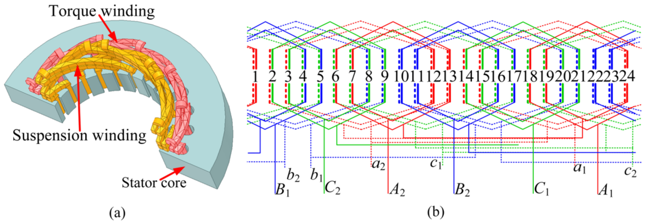
Figure 2a shows the structure of the stator. The stator is composed of the stator core and two windings. The stator core is formed by laminating 0.5 mm silicon steel sheets, and 24 slots are opened on the stator core in the designed motor. The slots of the stator core are embedded with torque winding and suspension force winding to provide torque and suspension force for the composite cage rotor, respectively. The torque winding and suspension force winding are placed at the bottom and top of the stator core, respectively. In the proposed motor, two windings are distributed in a single-layer concentric circle, and the torque winding and suspension force winding are powered by a high-voltage power supply and low-voltage power supply, respectively. The number of pole-pairs of the torque winding is 1, and the number of pole-pairs of the suspension force winding is 2. Figure 2b shows the distribution of torque winding and suspension force winding.
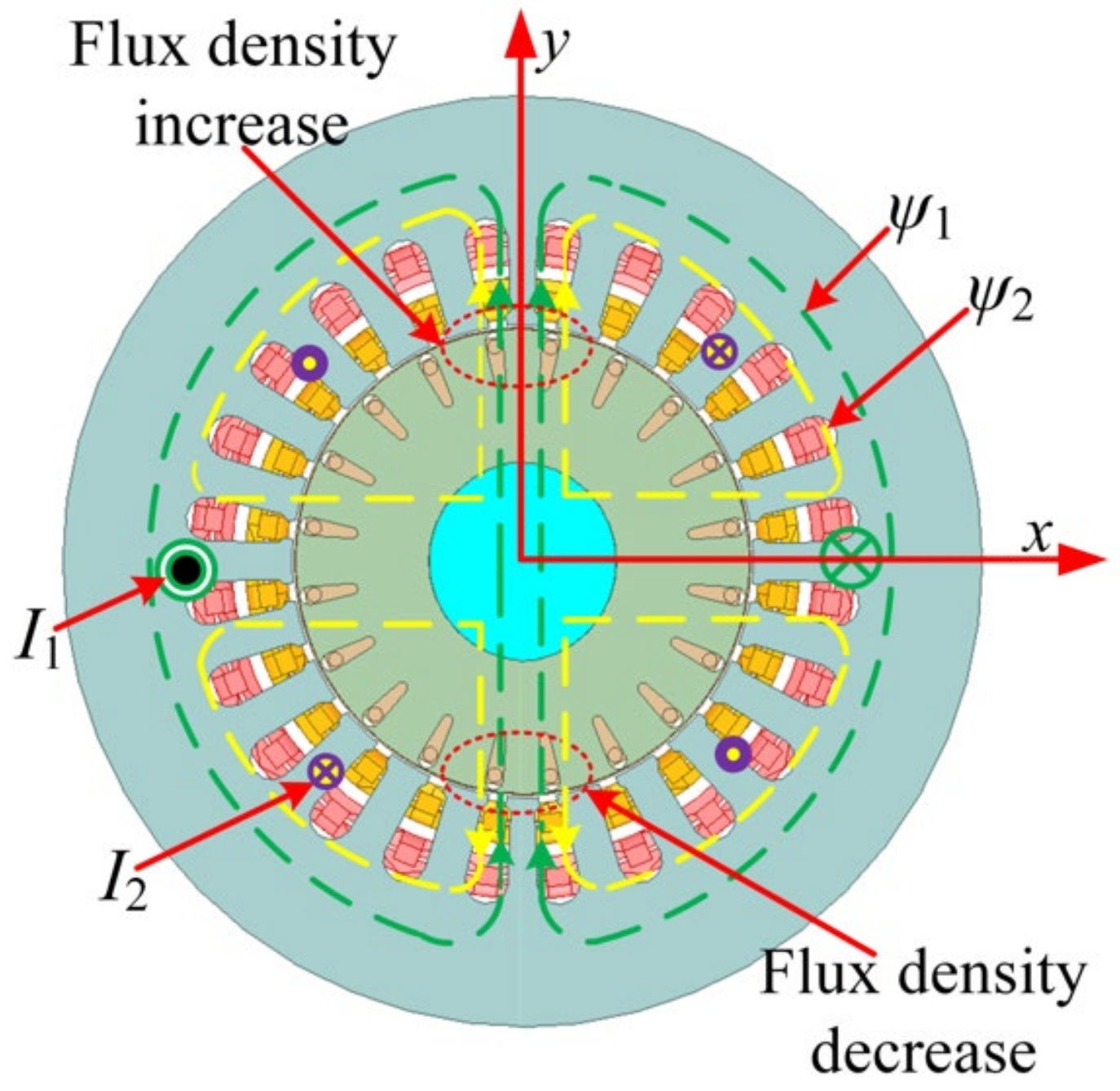
According to the basic principle of the bearingless motor, when the relationship between the number of pole-pairs of the torque winding and the suspension force winding is ±1, and the magnetic field rotation direction and electrical angular frequency of the two windings are consistent, the rotor will achieve stable suspension [13]. When the currents are injected into the two windings simultaneously, the magnetic field balance is destroyed, and the composite cage rotor will be subjected to Maxwell force in one direction in the unbalanced magnetic field. The direction of the radial force is changed by adjusting the initial phase angle difference between the torque winding current and suspension winding current. By setting the optimal initial phase angle difference, the radial force along the y-axis is obtained to realize the stable suspension of the composite cage rotor. The suspension mechanism is shown in Figure 3 [14].
The composite cage rotor is composed of an outer rotor and an inner rotor. The outer rotor is a solid layer, and the outer rotor is made of silicon steel with high magnetic permeability, which fits closely with the outer edge of the inner rotor. At the moment of starting, when the thickness of the outer rotor is less than or equal to the penetration depth of the electromagnetic wave, the outer rotor will play a major role in starting, which is similar to that of the solid rotor motor. Because of the skin effect of the outer rotor, the motor outputs greater starting torque. The inner rotor is a specially designed structure, which is composed of the rotor core, guide bars, and end rings. The inner rotor core is formed by laminating 0.35 mm silicon steel sheets, which is a part of the motor magnetic circuit, with 20 slots. The guide bars are made of aluminum with a radius of 0.35 mm, and the end rings of the inner rotor are made of copper. The composite cage rotor is shown in Figure 4.
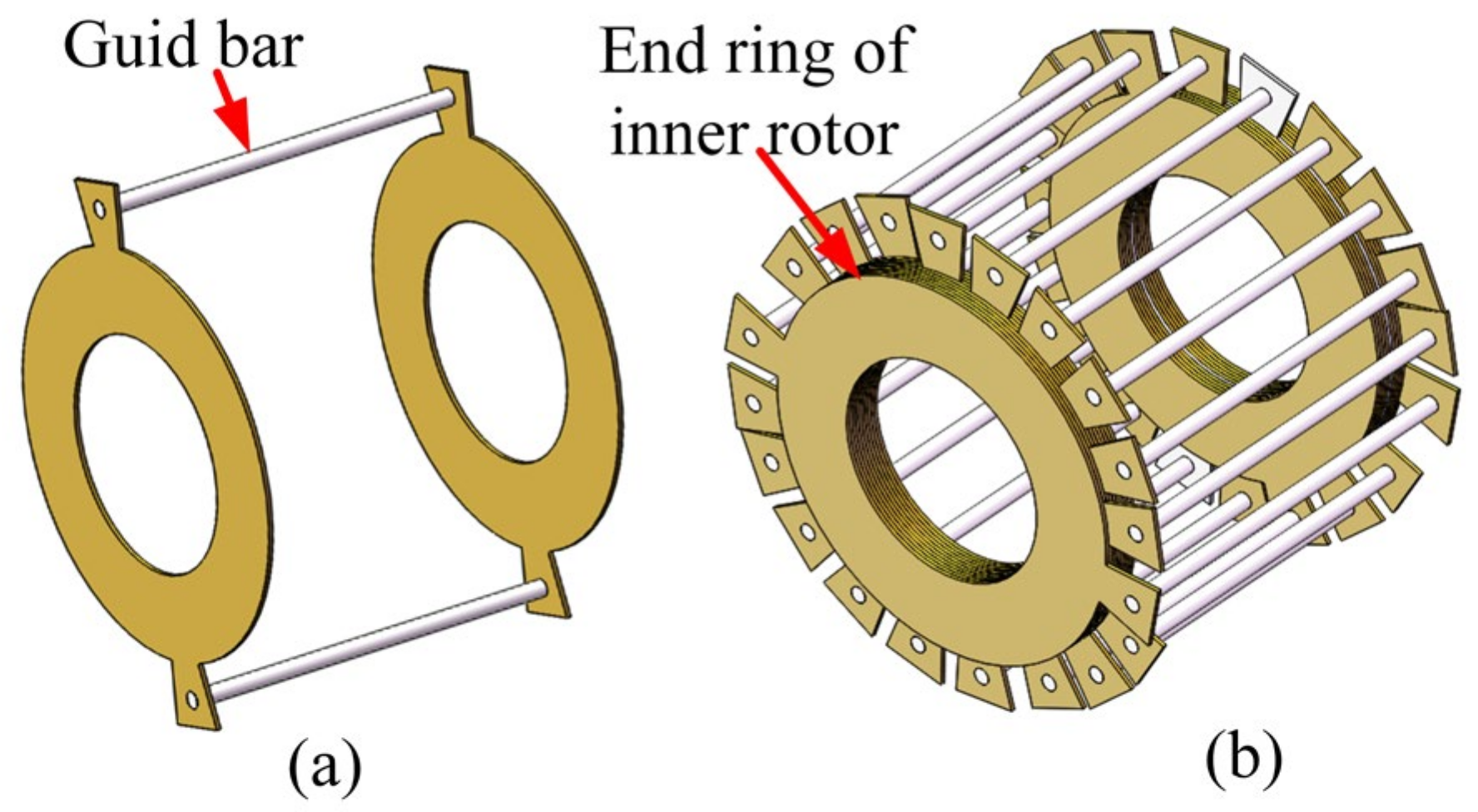
The two symmetrical guide bars and two end rings of the inner rotor form a special guide bar set (SPBS) through a closed connection, as shown in Figure 5a. Ten SPBSs are insulated from each other to form a special squirrel cage rotor structure, as shown in Figure 5b. This rotor structure of the inner rotor only senses the torque winding (P1 = 1). The induction mechanism is analyzed in Equations (1) and (2). The traditional BIM adopts a squirrel cage rotor structure; when the torque winding (P1 = 1) and suspension force winding (P2 = 2) work at the same time, both windings can induce rotor current. However, the squirrel cage rotor current induced by the suspension force winding will interfere with the torque, and the squirrel cage rotor current will also interfere with the rotor suspension. To overcome this problem, the special squirrel cage rotor structure of the inner rotor with induction only to the torque winding is designed.
Under the condition of odd and dipole magnetic fields, the magnetomotive force f(x,t) of three-phase symmetrical winding at any circumferential position x is expressed as
f ( x , t ) = F cos ( ω t P x )
where F is the amplitude of the basic magnetomotive force, and P is the number of pole-pairs of the winding.
The circumferential position x1 of the rotor is randomly selected, and the symmetrical circumferential position is x2. When P1 = 1 and P2 = 2, the magnetomotive force is written as
f 1 ( x 2 , t ) = F cos ( ω t x 2 ) = f 1 ( x 1 , t ) , P 1 = 1 f 2 ( x 2 , t ) = F cos ( ω t 2 x 2 ) = f 1 ( x 1 , t ) , P 2 = 2
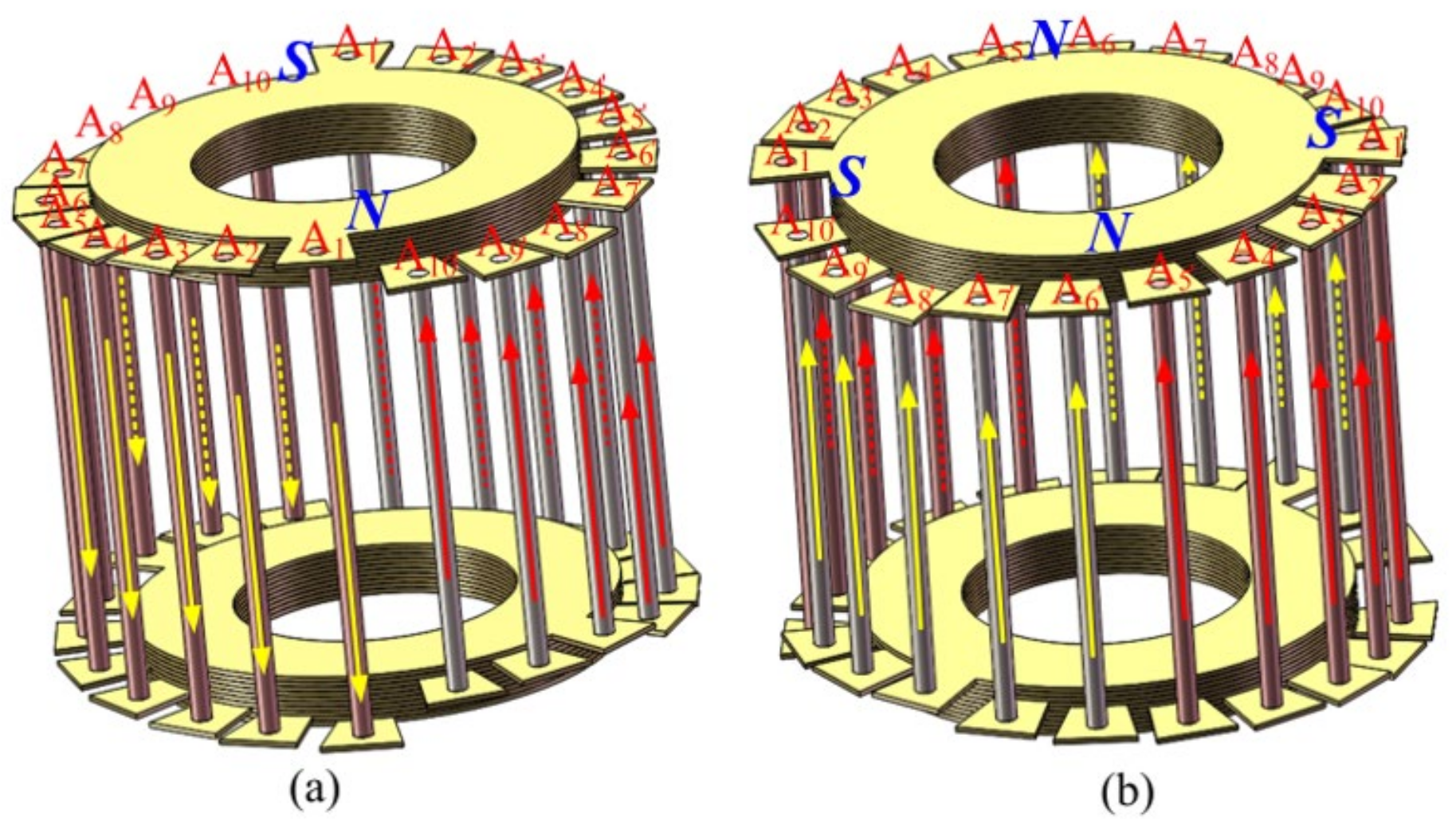
According to Equation (2), for the torque winding magnetic field (P1 = 1), the two directions of the induced electromotive force at the point x1, x2 are opposite to form a loop. For the suspension force winding magnetic field (P2 = 2), the induced electromotive force at the point x1, x2 has the same direction and cancels each other. The induced current distribution of torque and suspension force winding in the special squirrel cage rotor structure is shown in Figure 6. That is, there is only the induced current of torque winding in the guide bars.
When the motor runs smoothly, the motor slip is close to 0, the outer rotor will be penetrated by the magnetic line, and the inner rotor will play a major role. The motor will operate as a squirrel cage rotor BIM.

2.2. Mathematical Model of the CCR-BIM

2.2.1. Suspension Force Model

Based on the Maxwell force analysis, the basic suspension force model of the CCR-BIM is as follows (P2 = P1 ± 1) [15]:
F Σ x F Σ y = B 1 B 2 π r l 2 μ 0 cos θ s sin θ s + B 1 B 2 π r l ( μ A m μ F e ) 2 μ A m μ F e cos θ s sin θ s
where Fx and Fy are the resultant force components of the inner and the outer rotor along the x-axis and y-axis, B1 and B2 are the magnetic induction of the torque and the suspension force winding, r and r are the diameters of the inner and the outer rotor, l is the length of the proposed motor, μ0 is the air permeability, ωe1 and ωe2 are the electrical angular frequencies of the torque and the suspension force winding, θs is the initial angle difference between torque and suspension force winding, and μAm and μFe are the permeability of the outer rotor and inner rotor. Δ F 1 = B 1 B 2 π r l 2 μ 0 cos θ s sin θ s is the suspension force due to the inner rotor, and Δ F 2 = B 1 B 2 π r l ( μ A m μ F e ) 2 μ A m μ F e cos θ s sin θ s is the suspension force due to the outer rotor.
When μAm>>μFe, the increased suspension force due to the outer rotor is
Δ F 2 = B 1 B 2 π r l 2 μ F e cos θ s sin θ s
When μAm << μFe, the reduced suspension force due to the outer rotor is
Δ F 2 = B 1 B 2 π r l 2 μ A m cos θ s sin θ s
When the inner rotor and outer rotor are both made of silicon steel, that is μFe = μAm, then ΔF3 = 0. The outer rotor of this prototype is made of silicon steel and P1P2 = −1; therefore, the Equation (3) can be simplified as
F Σ x F Σ y = B 1 B 2 π r l 2 μ 0 cos θ s sin θ s
Therefore, the resultant force amplitude Fm is
F m = ( F Σ x ) 2 + ( F Σ y ) 2 = B 1 B 2 π r l 2 μ 0
Since the air gap flux of each phase of torque winding and suspension force winding is
φ 1 m = ϕ 1 N 1 = 2 r l B 1 P 1 N 1 ,   φ 2 m = ϕ 2 N 2 = 2 r l B 2 P 2 N 2
where φ1m is the air gap flux of the torque winding, and φ2m is the air gap flux of the suspension force winding,
then their three-phase synthetic air gap flux linkage is
φ 1 = 3 2 φ 1 m ,   φ 2 = 3 2 φ 2 m
The induced current of the suspension force winding in the rotor is ignored; then
φ 2 = L m 2 i 2
where Lm2 is the mutual inductance of suspension force winding.
Putting Equation (8), Equation (9), and Equation (10) into Equation (7), the resultant force amplitude Fm is
F m = π P 1 P 2 L m 2 φ 1 i s 2 18 μ 0 l r N 1 N 2
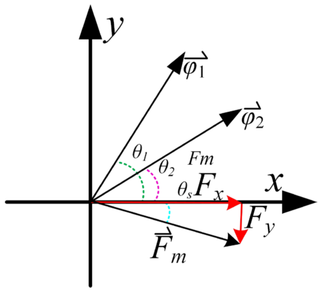
The vector diagram of the CCR-BIM Maxwell force is shown in Figure 7, where θs = θ2-θ1. Equation (6) can be decomposed into the d- and q-axis of the proposed motor, that is
F Σ x F Σ y = K m i s 2 d i s 2 q i s 2 q i s 2 d ψ r 1 d ψ r 1 q
where K m = π P 1 P 2 L m 2 φ 1 i s 2 18 μ 0 l r N 1 N 2 , is2d and is2q are the d-axis and q-axis components of the suspension force winding current, respectively, and ψr1d and ψr1q is the d-axis and q-axis magnetic flux components of torque winding, respectively.

2.2.2. Torque Model of the CCR-BIM

The stator voltage equation of torque winding is expressed as
U s 1 a U s 1 b U s 1 c = r s 1 i s 1 a i s 1 b i s 1 c + d ψ s 1 a d t d ψ s 1 b d t d ψ s 1 c d t
The rotor voltage equation is expressed as
U r 1 a U r 1 b U r 1 c = r r 1 i r 1 a i r 1 b i r 1 c + d ψ r 1 a d t d ψ r 1 b d t d ψ r 1 c d t
where Us1 and Ur1 are the stator and rotor voltages determined by their subscripts, respectively, and rs1 and rr1 are the equivalent resistances of the stator and rotor determined by their subscripts, respectively. ψ is the total flux linkage of each winding determined by their subscripts.
The mutual inductance between the stator and rotor is a function related to the position angle between the stator and rotor; the d-q coordinate transformation is introduced. Moreover, all rotor parameters are converted to the stator side. In the synchronous speed d-q transformation, the voltage equation is transformed into
U s 1 d U s 1 q U r 1 d U r 1 q = r s 1 r s 1 r r 1 r r 1 i s 1 q i s 1 d i r 1 q i r 1 d + d ψ s 1 q d t d ψ s 1 d d t d ψ r 1 q d t d ψ r 1 d d t + ω p ω p ( ω p ω r ) ( ω p ω r ) ψ s 1 d ψ s 1 q ψ r 1 d ψ r 1 q
The flux linkage equation is expressed as
ψ s 1 q ψ s 1 d ψ r 1 q ψ r 1 d = L s 1 σ L s 1 σ L r 1 σ L r 1 σ i s 1 q i s 1 d i r 1 q i r 1 d + L m 1 i s 1 q + i r 1 q i s 1 d + i r 1 d i s 1 d + i r 1 q i s 1 d + i r 1 d
The electromagnetic torque and rotor motion equations are expressed as
T e = p 1 L m 1 L s 1 σ ( i s 1 q i r 1 d i s 1 d i r 1 q )
where ωp is the synchronous angular speed, ωr is the rotor angular speed, Lm1 is the mutual inductance between the stator and rotor, Lr1 is the rotor leakage inductance of torque winding, Lσs and Lσr are the leakage inductances of each phase of the stator and rotor, respectively, and Us1 is the phase voltage amplitude of the torque winding.

3. Motor Optimization

3.1. Structure Parameter Setting

The basic parameter equation of the induction motor design is quoted, and the relationship between the structure size and electrical performance of the CCR-BIM is as follows [16,17]
D i l 2 l = 6.1 S c α p K w n K d p A B δ n
where Dil is the stator inner diameter, Sc is the apparent power, α p is the calculated pole arc coefficient, Kwn is the magnetic field waveform coefficient, Kdp is the stator winding coefficient, A is the line load, Bδ is the air gap flux density, and n is the synchronous speed.
At the start-up stage, the magnetic line of force cannot penetrate the solid layer of the outer rotor, so the thickness shall be greater than or equal to the penetration thickness. The equation of the penetration thickness of the outer rotor is [18]
Δ = 2 ω μ A m μ 0 σ
where σ is the conductivity. The initial parameter of the solid layer thickness of the outer rotor is set to 1.8 mm. Because there are errors in the calculation, the parameters need to be further optimized. According to the geometric similarity law in motor design, the stator and rotor dimensions of the CCR-BIM and traditional BIM have the same ratio. The structural parameters of the CCR-BIM are set according to the structural parameters of the traditional BIM.
The performance of the two motors is simulated with FEM. Figure 8 shows the structure and characteristic distribution of the two motors. The main parameters of the CCR-BIM and traditional BIM are listed in Table 1.
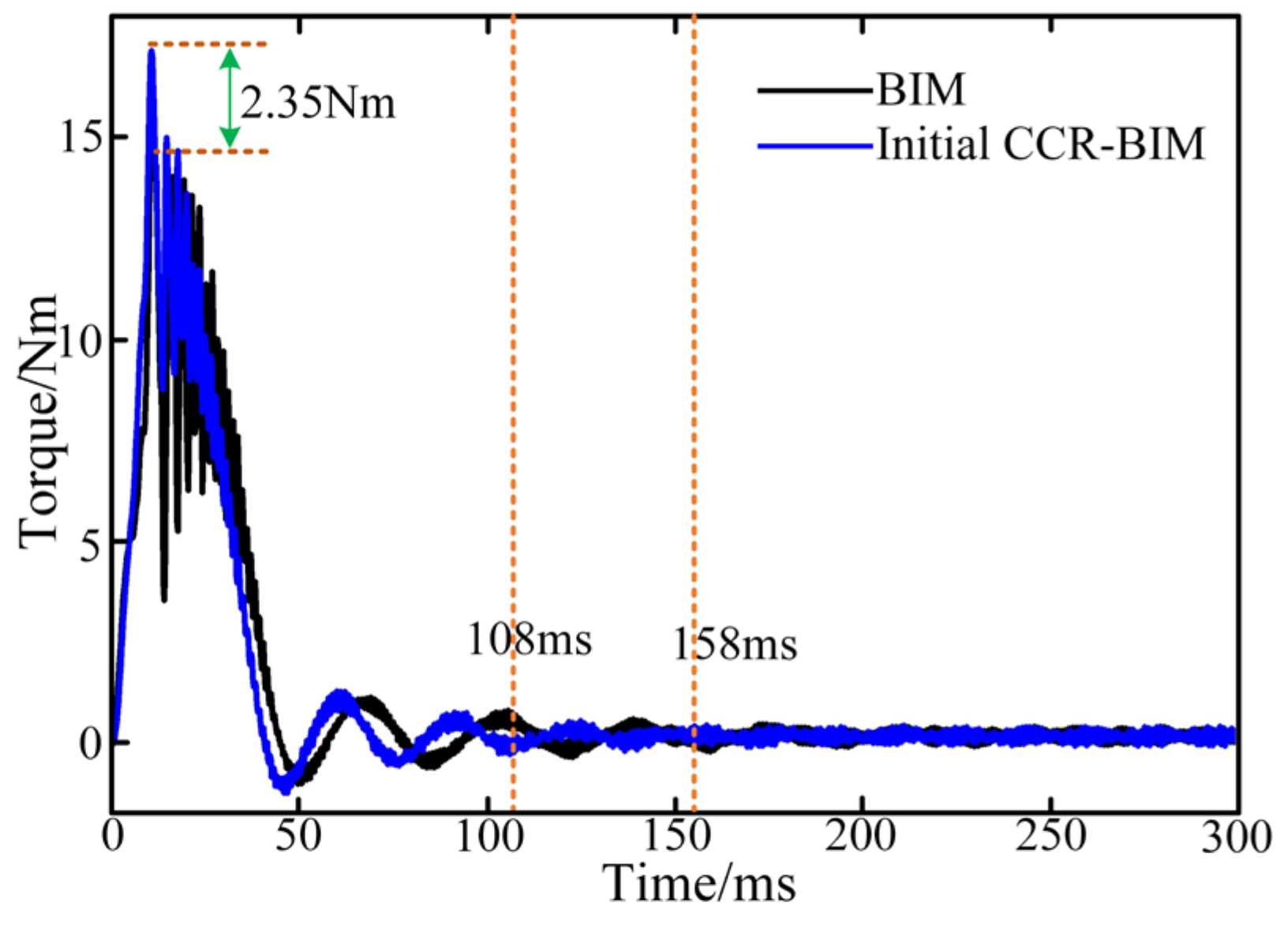
Figure 9 shows the torque characteristics between the CCR-BIM and the traditional BIM. In the start-up stage, the starting torque of the CCR-BIM reaches 17.31 Nm, while the starting torque of the BIM is 14.96 Nm. The torque of the CCR-BIM reaches a stable operation state in 108 ms, while the torque of the BIM needs 158 ms to reach stability. In the stable operation stage of the motor, the torque of CCR-BIM is more stable.
Figure 10 shows the suspension force between the CCR-BIM and the traditional BIM. In the start-up stage, when the same current value is input, the peak suspension force of the CCR-BIM is 69.45 N, which makes the starting process smoother and is conducive to the rapid and stable suspension of the rotor. The peak suspension force of the BIM is 116.32 N, which makes the suspension force vibrate more. The time for the suspension force of the CCR-BIM to reach stability is 96.72 ms, while the time for the suspension force of the BIM to reach stability is 117.53 ms; the time for the suspension force of the CCR-BIM to reach stability is shorter. When the motor reaches stable operation, the suspension force of the CCR-BIM is 40.67 N, while the stable suspension force of the BIM is only 36.22 N. When the motor reaches stable operation, the suspension force pulsation of the CCR-BIM is 0.62, and that of the BIM is 0.79. In conclusion, the suspension force of the CCR-BIM is smoother in the start-up stage and less fluctuating under the stable operation, which is more suitable for suspension requirements.

3.2. Optimization Objectives

Considering the application requirements of flywheel energy storage systems and suspension quality, the starting torque, the suspension force, and the suspension force pulsation are the observation objectives.
The starting torque Tst is defined as
T st = T max T a v g
where Tmax is the maximum torque from start to stable rotation, and Tavg is the average torque under stable rotation.
The average suspension force Favg under stable suspension is defined as
F a v g = i = 1 i = N F i N
where Fi is the values of suspension force at the sampling points, and N is the number of sampling points.
The suspension force pulsation Fpul under stable suspension is defined as
F p u l = F max F min F a v g
where Fmax and Fmin are the maximum and minimum values of the suspension force, respectively.
The optimization objective functions are
y T = T st y F = F a v g max y F p u l = F p u l min
The   constraints   are   y c s f 0.62 y F p u l 0.95
where yT, yF, and yFpul are, respectively, the objective function values of the starting torque, the suspension force, and the suspension force pulsation. Because the NSGA-II algorithm can only find the minimum value, the starting torque and average suspension force are preceded by a minus sign, respectively, in front of Tst and Favg. ycsf is the slot space factor. The slot space factor refers to the proportion of the space occupied by the windings after it is placed in the slot. If the slot space factor is too high, the slot insulation may be damaged, so the slot space factor is limited to 0.62. The suspension performance is an important index to measure the CCR-BIM. To ensure the stability of suspension, the suspension force pulsation cannot be too large, so yFpul cannot exceed 0.95.

3.3. Design of the Multi-objective Optimization

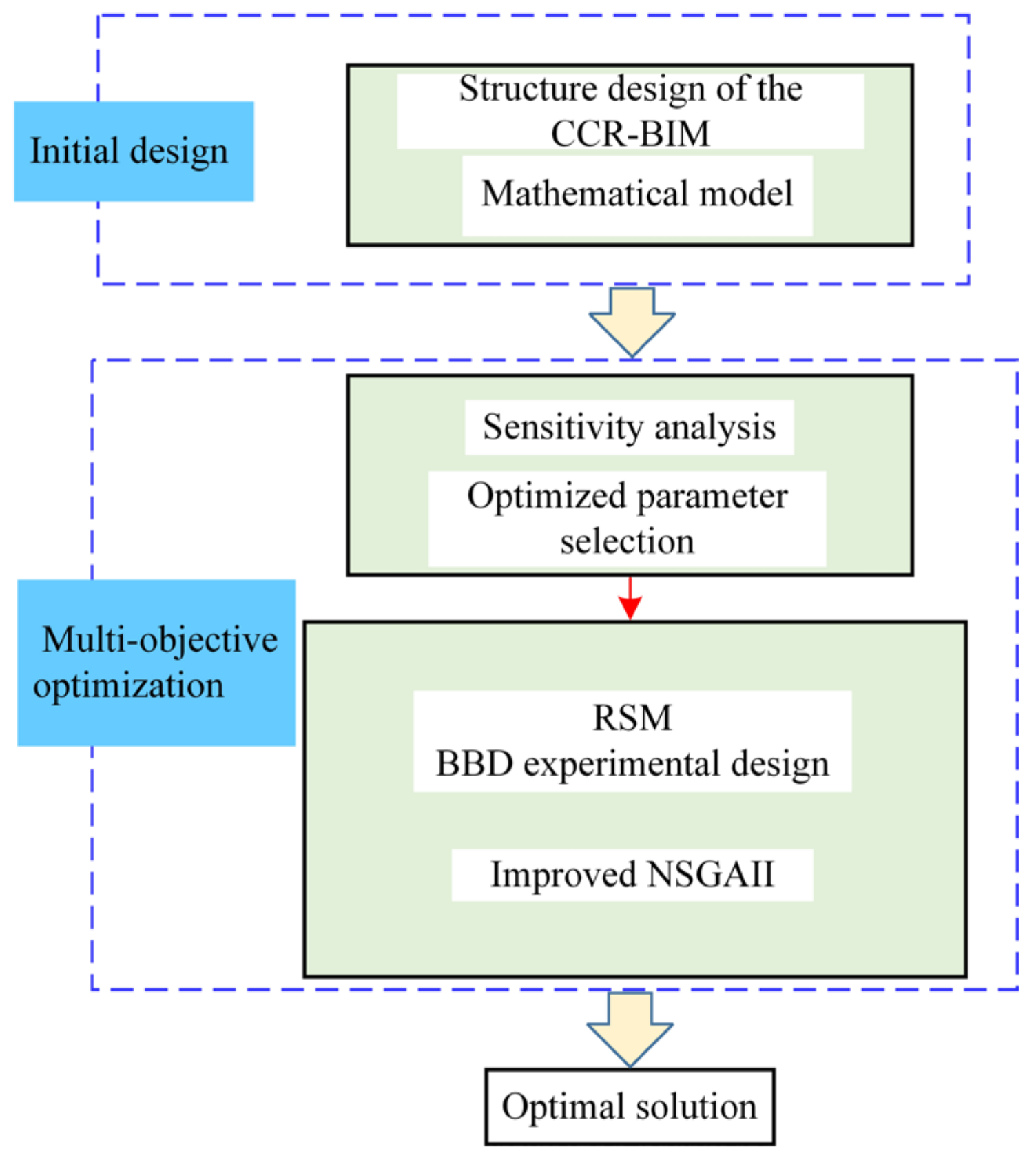
The optimization flowchart is shown in Figure 11. First, based on the analysis of the structure and mathematical model of the CCR-BIM motor, the objective parameters to be optimized are determined based on Equations (18) and (19), and the range of each parameter is given. Second, the sensitivity of the objective parameters is analyzed based on FEM, then the optimized parameters are selected. Third, based on NSGA-II, a variable neighborhood search (VNS) algorithm is introduced in the NSGA-II algorithm, which is called the improved NSGA-II algorithm. The parameters are optimized based on the improved NSGA-II. Finally, the optimized CCR-BIM with the optimal starting torque during motor start-up phase, the optimal suspension force, and the optimal suspension force pulsation under the stable rotation and suspension stage of the motor is obtained.

3.3.1. Sensitivity Analysis

Considering the structural parameter relationship of the motor and the limitation of the optimization objective, the initial optimized parameters and range settings of the proposed motor are shown in Table 2.
Considering the relevant parameters in Equation (18), the stator and rotor parameters of the CCR-BIM are optimized to obtain the optimal performance of the motor. In the stator, Sow, Sw1, Sw2, and Sh are selected as the initial optimized parameters. In the rotor, Hsl, L, Row, Rw1, Rw2, and Rh are selected as the initial optimized parameters. The stator and rotor parameters are marked as shown in Figure 12.
In this article, the sensitivity analysis method is utilized to determine the level of the optimization parameters. The calculation equation of the sensitivity parameters is as follows [19,20]:
S ( x i ) = g x i NOP x i g = Δ g / g Δ x i / x i
where xi is the optimization variable, g is the optimization objective, and S(xi) is the sensitivity index.
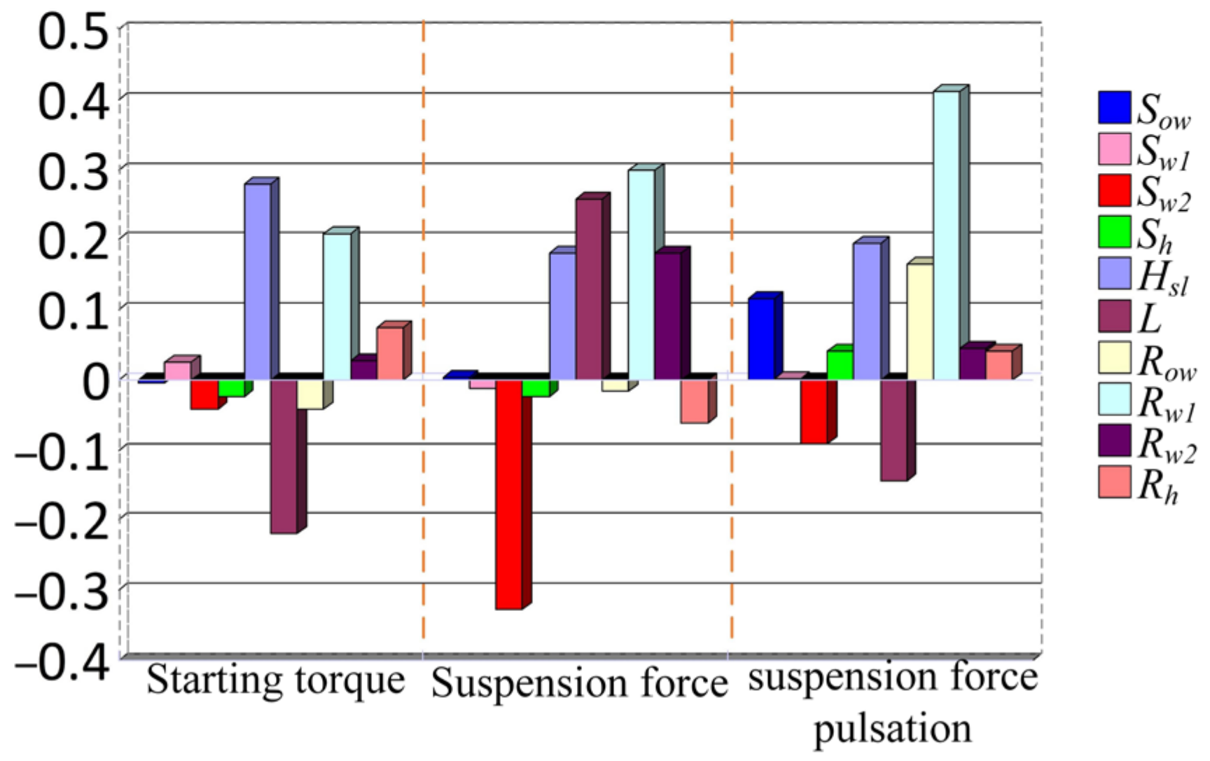
The sensitivity analysis of the stator and rotor parameters for the motor performance is shown in Figure 13. According to the comparative analysis in Figure 13, Sw2 has a great impact on the suspension force, L has a great impact on the starting torque and suspension force pulsation, and Hsl and Rw1 have the greatest impact on the three optimization objectives. Therefore, these four parameters are set as the optimized parameters. The influence of the other parameters is too little so can be ignored.
The optimization design strategy, combining RSM and the improved NSGAII, is adopted in this article. The RSM is obtained based on the Box–Behnken design (BBD), which can evaluate the nonlinear relationship between inputs and outputs and provides image analysis with continuity characteristics [21,22]. Since the optimal number of parameters in the BBD is 3–5, the number of optimized parameters is 4, which meets the requirements of the optimal parameters.

3.3.2. Optimization of the Parameters

RSM

The RSM is constructed based on the BBD, and the RSM of each optimization objective is shown in Figure 14. It is apparent that, within the selected parameter range, each optimization objective can obtain the optimal solution. However, when the three optimization objectives get the optimal solution, the values of the optimized parameters are inconsistent. To avoid conflicts between the optimization objectives and obtain a more reasonable solution set, a multi-objective intelligent optimization algorithm is adopted to get the Pareto solution.
Three fitting functions of the optimization objective are constructed from the RSM, and the fitting functions are in polynomial form, as shown in (25) [23].
g ( x i ) = β 0 + i = 1 n ( β i x i ) + i = 1 n j 1 n ( β i j x i x j ) + ε
where β0, βi, and βij are the coefficients of the fitting function, and ε is the error.
The fitting functions from Figure 14 are
Tst = 18.30 − 0.64*Hsl + 0.46*Rw1 − 0.60*Sw2 + 2.03*L + 0.77*Hsl*Rw1 − 3.58*Hsl*Sw2 + 0.46*Hsl*L − 2.26*Rw1*Sw2 + 1.06*Rw1*L − 0.19*Sw2*L − 2.66*Hsl^2 + 1.19*Rw1^2 − 2.88*Sw2^2 − 0.29*L^2.
Favg = 36.60 − 1.38*Hsl − 0.62*Rw1 − 0.41*Sw2 − 3.39*L − 0.62*Hsl*Rw1 + 5.98*Hsl*Sw2 − 1.10*Hsl*L + 2.60*Rw1*Sw2 − 1.99*Rw1*L + 0.096*Sw2*L + 3.89*Hsl^2 − 2.01*Rw1^2 + 4.80*Sw2^2 + 0.70*L^2.
Fpul = 0.63 + 0.028*Hsl + 0.016*Rw1 + 0.017*Sw2 + 0.060*L − 9.616E-004*Hsl*Rw1 − 0.020*Hsl* Sw2 + 0.043*Hsl*L − 1.433E-003*Rw1*Sw2 + 0.037*Rw1*L + 4.827E − 003*Sw2*L − 0.038*Hsl^2 + 0.031* Rw1^2 − 0.045*Sw2^2 + 0.017*L^2.

Optimization Design Based on the Improved NSGA-II

The algorithm has a high probability of falling into the local optimum. Therefore, a variable neighborhood search (VNS) algorithm is introduced in the NSGA-II algorithm. By introducing the inverse operator and the pairwise operator, some gene sequences of the current solution are changed to generate a neighborhood feasible solution set so as to avoid the solution generated in the process of population evolution from falling into the local optimum. An improved NSGA-II algorithm is designed.
Insert operator: Two positions, Qi and Qj, are randomly selected; Qj is inserted in front of Qi, and the other positions change one position in turn. The insert operator operation is shown in Figure 15.
Inverse operator: Two positions, Qj−1 and Qj+1, are randomly selected, and the gene sequences between the positions are reversed. The inverse operator operation is shown in Figure 16.
Swap operator: Two positions, Qi and Qj, are randomly selected, and the two positions are exchanged. The swap operator operation is shown in Figure 17.
Pairwise operator: The positions of two adjacent genes are exchanged, that is, the first and second genes are exchanged, the third and fourth genes are exchanged, and so on. Finally, if there is a single process left, it will not change. The pairwise operator operation is shown in Figure 18.
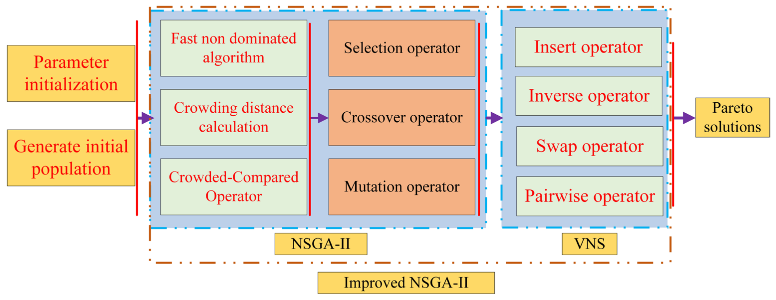
Based on the improved NSGA-II, this paper first obtains a new population through a fast non-dominated algorithm, crowding distance calculation, crossover operation, and mutation operation, and then combines the VNS algorithm to get the multi-objective optimization Pareto solutions. The algorithm flow is shown in Figure 19. The initial population samples are set to 400, and the number of iterations is set to 300.
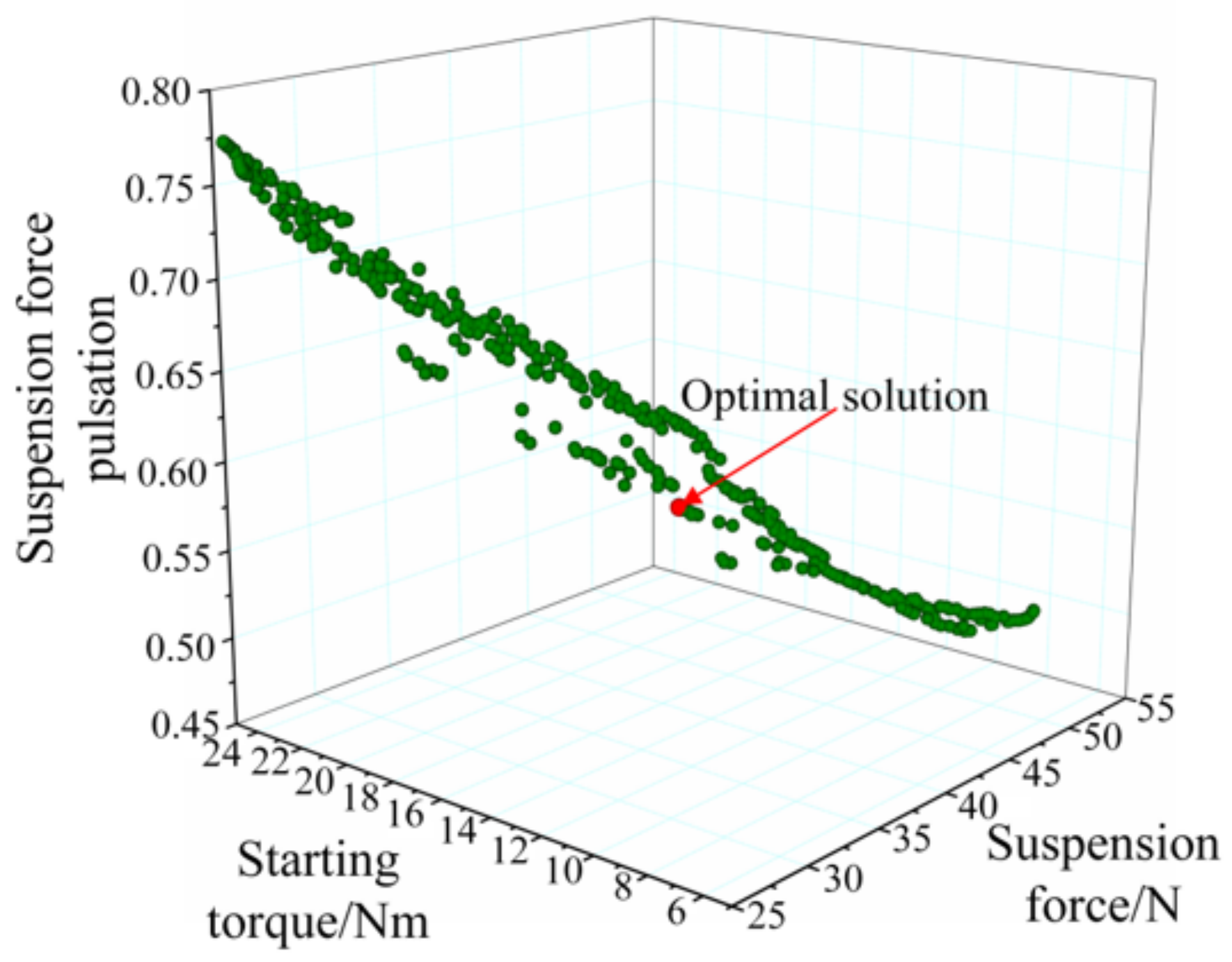
The Pareto solution set and optimal solution are shown in Figure 20. The optimum value of the corresponding sensitive parameters is Rw1 = 3.61 mm, Hsl = 1.97 mm, L = 82.85 mm, and Sw2 = 5.84 mm. The starting torque is 18.4 Nm, the suspension force is 43.26 N, and the suspension force pulsation is 0.53 when the motor runs stably. Compared with the before-optimization state in Figure 9 and Figure 10, the starting torque has increased by 6.29%, the suspension force has increased by 6.36%, the suspension force pulsation has been reduced by 14.51%, and the performance of the CCR-BIM has been effectively improved (as shown in Table 3).

4. Experimental Verification

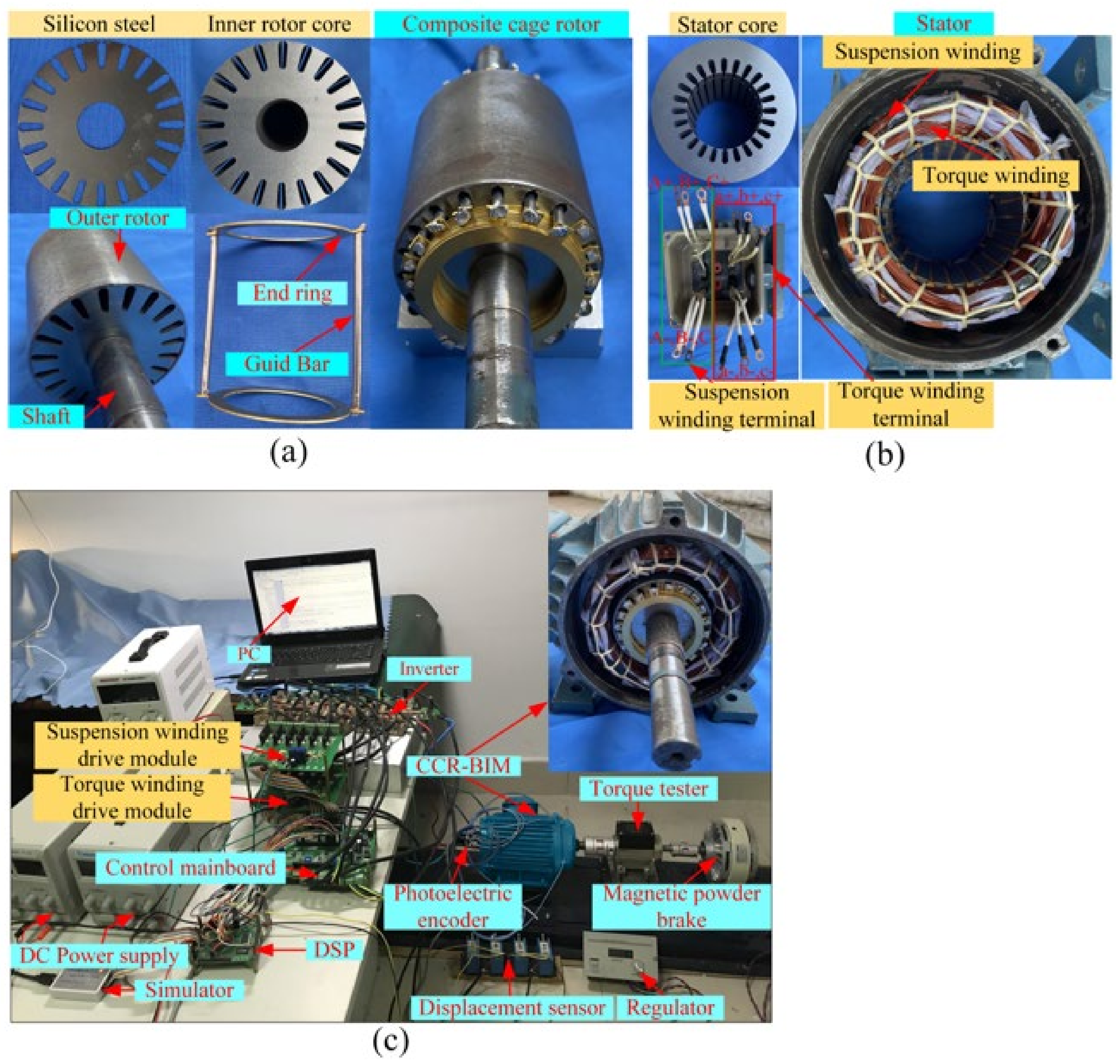
To verify the correctness of the motor structure and designed optimization strategy, the composite cage rotor and experimental prototypes are manufactured based on the initial and optimal parameters. In addition, the traditional BIM is also involved in the comparison, and the performance of the three motors is compared. The experimental platform is shown in Figure 21. Figure 21a and Figure 21b show the composite cage rotor structure and stator structure, respectively. Figure 21c shows the motor test bench, which mainly consists of the prototype, DSP, photoelectric encoder, displacement sensor, inverter, torque tester, and so on.
The air gap field-oriented control is applied to the motor test bench [24,25]. The CCR-BIM control system is composed of the speed control system and the suspension control system. Because the CCR-BIM has the double-winding structure, and there is a coupling phenomenon, the air gap field-oriented control strategy is adopted to realize the decoupling of the control system. The speed and displacement fed back by the motor are used to control the two systems separately through PID. Figure 22 shows the control system.
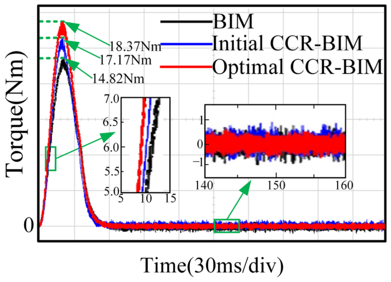
Figure 23 shows the torque response between the BIM, the initial CCR-BIM, and the optimal CCR-BIM. In the start-up phase, the starting torque response of the CCR-BIM is more sensitive. The starting torque of the optimal CCR-BIM is 18.37 Nm, and the starting torque of the initial CCR-BIM is 17.17 Nm. They are all greater than the 14.82 Nm torque of the BIM. In the stable rotation and suspension stage, the torque ripple of the optimal CCR-BIM is smaller, and the operation is more stable, which proves that the torque quality of the CCR-BIM has been improved.
Figure 24 shows the current waveform of suspension force winding A. The suspension force cannot be measured directly on the experimental platform. However, when the rotor mass of the motor is certain, by adjusting the current of the suspension force winding, the suspension force can be indirectly reflected by the current of the suspension force winding when the motor is stably suspended. I1 represents torque winding current, and I2 represents suspension winding current. The suspension force winding current I2 of the optimal CCR-BIM is 0.43 A, the suspension force winding current I2 of the initial CCR-BIM is 0.46 A, and the suspension force winding current of the BIM is 0.5 A. When the rotor weight is equal, the suspension current of the CCR-BIM decreases. Compared with the current waveform of the suspension force winding of the optimal CCR-BIM, the initial CCR-BIM, and the traditional BIM, the suspension force winding current of the optimal CCR-BIM is smoother. It is proved that the suspension force and suspension quality of the CCR-BIM have been improved.
The suspension pulsation cannot be measured directly through the experimental platform, which is reflected by the x-axis radial displacement and the trajectory at the end of the rotating shaft. Figure 25 shows the trajectory at the end of the rotating shaft of the three motors, which can show the performance of the suspension force pulsation. The maximum fluctuation amplitude is marked as Dmax, which is the result of the interaction between the x-axis radial displacement and the y-axis radial displacement. Through comprehensive calculation, the Dmax of the BIM is 72.4 μm, the Dmax of the initial CCR-BIM is 52.1 μm, and the Dmax of the optimal CCR-BIM is 43.1 μm. The trajectory at the end of the rotating shaft of the optimal CCR-BIM is smaller, which reduces the radial offset in any direction and improves the suspension quality.
Based on the test of the experimental platform, the final results of the optimization objectives are shown in Table 4. Compared with the initial CCR-BIM and the optimal CCR-BIM, the starting torque is increased by 6.98%. The average suspension force and suspension fluctuation are indirectly reflected by the suspension current and the trajectory at the end of the rotating shaft. Under the same rotating shaft quality, the suspension current of the optimal CCR-BIM is 5.45% lower than the suspension current of the initial CCR-BIM, and the Dmax of the optimal CCR-BIM is 18.54% smaller than that of the initial CCR-BIM.

5. Conclusions

This work includes a motor design and multi-objective optimization. In this paper, a composite cage rotor bearingless induction motor structure is proposed, especially for the composite cage rotor structure, which is specially designed. The skin effect of the outer rotor improves the starting performance of the motor. The inner rotor adopts a special design structure that only induces the torque winding, which avoids the interference of the suspension winding on the torque, and the suspension quality is also improved. The research results are as follows:
(1) The structural characteristics of the proposed motor are analyzed, the mathematical model of the motor is deduced, and the initial structural parameters of the motor are determined. A FEM is established, and the electromagnetic properties, such as suspension quality and torque quality, between the traditional BIM and CCR-BIM are compared and analyzed.
(2) The multi-objective improved NSGA-II based on RSM is adopted, the motor parameters are optimized with the motor torque quality and suspension quality as the optimization goals, and the optimal performance parameters are determined.
(3) The experimental prototype is processed, and the experimental research is carried out. The results show that the proposed motor meets the design requirements, which verifies the correctness of the motor structure and the effectiveness of the design method, and the torque quality and suspension quality of the motor are improved.

Author Contributions

Conceptualization, C.L. and Z.Y.; methodology, C.L.; software, Q.D.; validation, C.L. and Q.D.; formal analysis, Z.Y.; investigation, C.L.; resources, C.L. and Z.Y.; data curation, C.L.; writing—original draft preparation, C.L.; writing—review and editing, C.L.; visualization, C.L.; supervision, Z.Y.; project administration, Z.Y.; funding acquisition, Z.Y. and X.S. All authors have read and agreed to the published version of the manuscript.

Funding

This work was supported by the National Natural Science Foundation of China (51875261); Natural Science Foundation of Jiangsu Province (BK20221366); and Doctoral Research and Innovation Project of Jiangsu Province (KYCX21_3362).

Data Availability Statement

Not applicable.

Conflicts of Interest

The authors declare no conflict of interest.

References

  1. Zhu, H.; Li, H. Magnetic Field Equivalent Current Analysis-Based Radial Force Control for Bearingless Permanent Magnet Synchronous Motors. Energies 2015, 8, 4920–4942. [Google Scholar] [CrossRef]
  2. Noh, M.; Trumper, D.L. Homopolar Bearingless Slice Motor With Flux-Biasing Halbach Arrays. IEEE Trans. Ind. Electron. 2019, 67, 7757–7766. [Google Scholar] [CrossRef] [PubMed]
  3. Yang, Z.; Jia, J.; Sun, X.; Xu, T. An Enhanced Linear ADRC Strategy for a Bearingless Induction Motor. IEEE Trans. Transp. Electrif. 2021, 8, 1255–1266. [Google Scholar] [CrossRef]
  4. Mousavi G, S.M.; Faraji, F.; Majazi, A.; Al-Haddad, K. A comprehensive review of Flywheel Energy Storage System technology. Renew. Sustain. Energy Rev. 2017, 67, 477–490. [Google Scholar] [CrossRef]
  5. Ding, Q.; Yang, Z.; Sun, X.; Zhao, Q.; Zhu, H. Analysis of rotor slot width influence on a bearingless induction motor. Comput. Electr. Eng. 2019, 81, 106534. [Google Scholar] [CrossRef]
  6. Chiba, A.; Fukao, T. Optimal design of rotor circuits in induction type bearingless motors. IEEE Trans. Magn. 1998, 34, 2108–2110. [Google Scholar] [CrossRef]
  7. Sun, Y.; Tang, J.; Shi, K. Design of a Bearingless Outer Rotor Induction Motor. Energies 2017, 10, 705. [Google Scholar] [CrossRef]
  8. Hua, Y.; Zhu, H.; Xu, Y. Multi-Objective Optimization Design of Bearingless Permanent Magnet Synchronous Generator. IEEE Trans. Appl. Supercond. 2020, 30, 5201205. [Google Scholar] [CrossRef]
  9. Huang, C.; Kou, B.; Zhao, X.; Niu, X.; Zhang, L. Multi-Objective Optimization Design of a Stator Coreless Multidisc Axial Flux Permanent Magnet Motor. Energies 2022, 15, 4810. [Google Scholar] [CrossRef]
  10. Ilka, R.; Alinejad-Beromi, Y.; Yaghobi, H. Cogging torque reduction of permanent magnet synchronous motor using multi-objective optimization. Math. Comput. Simul. 2018, 153, 83–95. [Google Scholar] [CrossRef]
  11. Si, J.; Yan, Z.; Nie, R.; Li, Z.; Hu, Y.; Li, Y. Multi-objective optimization of a tubular permanent magnet linear generator with 120° phase belt toroidal windings using response surface method and genetic algorithm. IET Renew. Power Gener. 2021, 16, 352–361. [Google Scholar] [CrossRef]
  12. Jiang, R.; Jin, Z.; Liu, D.; Wang, D. Multi-Objective Lightweight Optimization of Parameterized Suspension Components Based on NSGA-II Algorithm Coupling with Surrogate Model. Machines 2021, 9, 107. [Google Scholar] [CrossRef]
  13. Sharifi, M.; Mojallali, H. Multi-Objective Modified Imperialist Competitive Algorithm for Brushless DC Motor Optimization. IETE J. Res. 2017, 65, 96–103. [Google Scholar] [CrossRef]
  14. Yang, Z.; Ji, J.; Sun, X.; Zhu, H.; Zhao, Q. Active Disturbance Rejection Control for Bearingless Induction Motor Based on Hyperbolic Tangent Tracking Differentiator. IEEE J. Emerg. Sel. Top. Power Electron. 2019, 8, 2623–2633. [Google Scholar] [CrossRef]
  15. Lu, C.; Yang, Z.; Sun, X.; Ding, Q.; Zhao, Q. A decoupling control of composite cage rotor bearingless induction motor based on SA-PSO support vector machine inverse. Int. Trans. Electr. Energy Syst. 2021, 31, e12988. [Google Scholar] [CrossRef]
  16. Chen, S. Motor Design; China Machine Press: Beijing, China, 2000; pp. 9–18. [Google Scholar]
  17. Zhu, H.; Shen, S.; Wang, X. Multiobjective Optimization Design of Outer Rotor Coreless Bearingless Permanent Magnet Synchronous Motor. IEEE J. Emerg. Sel. Top. Power Electron. 2021, 9, 5489–5498. [Google Scholar] [CrossRef]
  18. Gieras, J.F.; Saari, J. Performance Calculation for a High-Speed Solid-Rotor Induction Motor. IEEE Trans. Ind. Electron. 2011, 59, 2689–2700. [Google Scholar] [CrossRef]
  19. Andriushchenko, E.; Kallaste, A.; Mohammadi, M.H.; Lowther, D.A.; Heidari, H. Sensitivity Analysis for Multi-Objective Optimization of Switched Reluctance Motors. Machines 2022, 10, 559. [Google Scholar] [CrossRef]
  20. Mahmouditabar, F.; Vahedi, A.; Mosavi, M.R.; Bafghi, M.H.B. Sensitivity analysis and multiobjective design optimization of flux switching permanent magnet motor using MLP-ANN modeling and NSGA-II algorithm. Int. Trans. Electr. Energy Syst. 2020, 30, e12511. [Google Scholar] [CrossRef]
  21. Zhu, Z.; Zhu, J.; Zhu, H.; Zhu, X.; Yu, Y. Optimization Design of an Axial Split-Phase Bearingless Flywheel Machine with Magnetic Sleeve and Pole-Shoe Tooth by RSM and DE Algorithm. Energies 2020, 13, 1256. [Google Scholar] [CrossRef] [Green Version]
  22. Nguyen, H.L.; Duy, L.T. Using the Box–Behnken Response Surface Method to Study Parametric Influence to Improve the Efficiency of Helical Gears. Machines 2021, 9, 264. [Google Scholar] [CrossRef]
  23. Liu, G.; Wang, Y.; Chen, Q.; Xu, G.; Song, C. Multiobjective Deterministic and Robust Optimization Design of a New Spoke-Type Permanent Magnet Machine for the Improvement of Torque Performance. IEEE Trans. Ind. Electron. 2020, 67, 10202–10212. [Google Scholar] [CrossRef]
  24. Suzuki, T.; Chiba, A.; Rahman, M.A.; Fukao, T. An air-gap-flux-oriented vector controller for stable operation of bearingless induction motors. IEEE Trans. Ind. Appl. 2000, 36, 1069–1076. [Google Scholar] [CrossRef]
  25. Bu, W.; Cheng, X.; He, F.; Qiao, Y.; Zhang, H.; Xu, X. Inverse system modeling and decoupling control of bearingless induction motor based on air gap flux orientation. Int. J. Appl. Electromagn. Mech. 2017, 53, 567–577. [Google Scholar] [CrossRef]
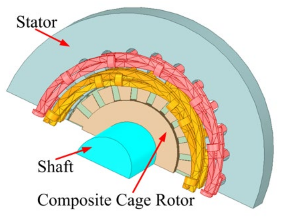
Figure 1. Sectional view of the CCR-BIM motor.
Electronics 12 00775 g001
Figure 2. Stator and winding distribution. (a) Stator structure; (b) Torque winding (Dotted line: P1 = 1), suspension force winding (Solid line: P2 = 2).
Electronics 12 00775 g002
Figure 3. Suspension mechanism.
Electronics 12 00775 g003
Figure 4. Composite Cage Rotor.
Electronics 12 00775 g004
Figure 5. Special squirrel cage rotor structure. (a) Special guide bar set; (b) special squirrel cage rotor structure.
Electronics 12 00775 g005
Figure 6. Current distribution of the special squirrel cage structure. (a) P1 = 1; (b) P2 = 2.
Electronics 12 00775 g006
Figure 7. Maxwell force vector diagram.
Electronics 12 00775 g007
Figure 8. Structure and characteristic distribution. (a) CCR-BIM; (b) Traditional BIM.
Electronics 12 00775 g008
Figure 9. Torque characteristics.
Electronics 12 00775 g009
Figure 10. Suspension force.
Electronics 12 00775 g010
Figure 11. Optimization flowchart.
Electronics 12 00775 g011
Figure 12. Optimized parameters of the stator and rotor. (a) Stator slot parameters; (b) Rotor slot parameters; (c) Rotor parameters.
Electronics 12 00775 g012
Figure 13. Sensitivity index.
Electronics 12 00775 g013
Figure 14. RSM based on sensitive parameters. (a) Starting torque; (b) Suspension force; (c) Suspension force pulsation.
Electronics 12 00775 g014
Figure 15. Neighborhood transformation of insert operator.
Electronics 12 00775 g015
Figure 16. Neighborhood transformation of inverse operator.
Electronics 12 00775 g016
Figure 17. Neighborhood transformation of swap operator.
Electronics 12 00775 g017
Figure 18. Neighborhood transformation of pairwise operator.
Electronics 12 00775 g018
Figure 19. Flowchart of the improved NSGAII.
Electronics 12 00775 g019
Figure 20. The Pareto solution set and optimal solution.
Electronics 12 00775 g020
Figure 21. Experimental platform: (a) Rotor structure; (b) Stator structure; (c) Motor test bench.
Electronics 12 00775 g021
Figure 22. Control block diagram.
Electronics 12 00775 g022
Figure 23. Torque response.
Electronics 12 00775 g023
Figure 24. Current of suspension force winding A.
Electronics 12 00775 g024
Figure 25. Trajectory of the rotating shaft.
Electronics 12 00775 g025
Table 1. Main parameters.
Parameter NameCCR-BIMBIM
Rated power1.8 kW1.8 kW
Rated speed3000 r/min3000 r/min
Rated efficiency0.820.80
Rated current of torque winding3.0 A3.0 A
Rated current of suspension force winding0.5 A0.5 A
Inner diameter of stator65 mm65 mm
Outer diameter of stator122 mm122 mm
Air gap0.3 mm0.3 mm
Motor inertia7.69 g·m27.67 g·m2
Turns of torque winding6060
Turns of suspension force winding5050
Silicon steel materialB50B50
Table 2. Initial value and range of optimized parameters.
SymbolDesign VariableInitial ValueRange
SowNotch width of stator 2.5 mm2.0–3.0 mm
Sw1Slot width of stator4.5 mm4.2–4.8 mm
Sw2Slot bottom width of stator6.0 mm4.8–7.6 mm
ShSlot depth of stator8.2 mm7.6–8.8 mm
HslThickness of outer rotor1.8 mm1.7–2.0 mm
LCore length of composite rotor80.0 mm70–90 mm
RowNotch width of inner rotor 0.8 mm0.6–1.1 mm
Rw1Slot width of inner rotor3.2 mm2.8–4.4 mm
Rw2Slot bottom width of inner rotor1.7 mm0.8–2.6 mm
RhSlot depth of the inner rotor7.0 mm6.5–7.5 mm
Table 3. Optimization results of FEM.
ObjectivesTraditional BIMInitial
CCR-BIM
Optimal
CCR-BIM
Optimization Effect
Tst14.96 Nm17.31 Nm18.40 m↑6.29%
Favg36.22 N40.67 N43.26 Nm↑6.36%
Fpul0.790.620.53↓14.51%
Table 4. Experimental Results.
ObjectivesTraditional BIMInitial CCR-BIMOptimal CCR-BIMOptimization Effect
Tst14.82 Nm17.17 Nm18.37 Nm↑6.98%
I2 (Favg)0.5 A0.46 A0.43 A↓5.45%
Dmax (Fpul)72.4 μm52.3 μm42.6 μm ↓18.54%
Disclaimer/Publisher’s Note: The statements, opinions and data contained in all publications are solely those of the individual author(s) and contributor(s) and not of MDPI and/or the editor(s). MDPI and/or the editor(s) disclaim responsibility for any injury to people or property resulting from any ideas, methods, instructions or products referred to in the content.