1. Introduction
The object detection (OD) aims to find all objects of interest in an image, determining their class and location. OD is one of the core problems in the field of computer vision. Recently, domestic and foreign professional scholars have made unremitting efforts in the field of object detection (OD); thus, many representative algorithms have emerged. OD algorithms have resulted in significant breakthroughs, from the classical Faster R-CNN [
1] to the more recent DCNv2 [
2] and YOLObile [
3], and from the AlexNet to ResNetX [
4] and AmoebaNet [
5] networks. However, research on the hardware acceleration of mainstream OD algorithms has rarely been conducted, and the existing research has suffered from insufficient acceleration methods, high-power consumption, and imperfect memory access optimization. To satisfy the higher speed and accuracy of OD algorithms with less hardware resource loss, multiple new optimization schemes and hardware acceleration solutions have been proposed. Sze et al. [
6] proposed an FFT method to reduce matrix multiplication. However, more hardware resources are consumed by FFT itself; thus, it cannot meet the requirement of minimal loss in hardware resources. Nakahara et al. [
7] designed a set of optimization acceleration platforms that combine a binary and support vector machine in lightweight YOLOv2 to accelerate the detection speed of the you only look once (YOLO) algorithm by reducing computational complexity. However, this method does not consider memory access optimization and can only optimize the performance of YOLO, which cannot meet the acceleration of multiple OD algorithms. Ma et al. [
8] analyzed the design possibilities of convolutional loop unfolding-based SIMD architectures. However, the proposed architecture caches both feature image elements and weights on chip, resulting in the consumption of excessive FPGA resources. A generic construction method of convolutional neural networks (CNNs) for embedded FPGA platforms for edge computing was proposed by Lu et al., but the evaluation model was quite simple [
9].
Therefore, on the basis of previous research [
10,
11] and the accelerator structure proposed by Fen et al. [
12], this study further optimized the accelerator structure used by previous researchers and interconnected the basic operation modules in the acceleration chain through cross-switches; hence, the input data became more flexible and multi-selective. The hardware structure of the coprocessor was designed based on the design instructions. Meanwhile, the coprocessor instructions were encapsulated as function interfaces in the form of C language inline assembly. Finally, coprocessor resource evaluation was conducted based on Xilinx FPGA. Two instruction sets were used to realize convolution, pooling, ReLU, and other basic unit algorithms. The operation cycle of each algorithm was compared in two ways and then applied to the current popular OD algorithms, and their performance was compared with that of other accelerators. The following are the innovative points of this study:
The basic units in the acceleration chain were interconnected through cross-switches, allowing a more diverse flow of input data and hence enabling the acceleration of mainstream OD algorithms.
The common points of the network structure of mainstream OD algorithms were extracted, and the operation of external data access was reduced, making the accelerator support different networks and complete the accelerated application of various networks with less resource consumption.
The accelerator was converted into a coprocessor and then connected to the E203 kernel, which reduced data movement, improved the code density, and further expedited the processing speed of an OD algorithm.
2. Related Work
Conventional OD algorithms mainly detect a limited number of classes by using Adaboost, support vector machine (SVM), and deformable part model algorithms. However, these algorithms have many drawbacks, and conventional OD algorithms are rarely used nowadays. Therefore, this study did not consider the acceleration of these conventional algorithms.
With researchers’ continuous exploration, research on OD algorithms is mainly based on deep learning. This study also focused on the hardware acceleration of mainstream deep learning OD algorithms. In the ImageNet competition, AlexNet based on CNN feature extraction outperformed all hand-designed feature extractors and successfully reintroduced neural vision networks. Generally, popular algorithms can be divided into two categories. The first is the two-stage algorithm, which is based on candidate regions [
13] of the R-CNN family algorithms (i.e., R-CNN, Fast R-CNN, Faster R-CNN [
1], R-FCN [
14], and Mask R-CNN [
15]). The other is a one-stage algorithm (e.g., YOLOv3 [
16], SSD [
17], DSSD [
18], and RetinaNet [
19]). The main concept of the two-stage algorithm is to generate a series of sparse candidate frames by a selective search or using a CNN network, and then the classification and regression of these candidate frames are used. The advantage of the two-stage algorithm is its high accuracy. The main concept of the one-stage algorithm is mainly based on uniform dense sampling at different locations of an image, wherein different ratios and aspect ratios are used when sampling. Moreover, a CNN is used to extract features and then directly classify and regress them. The entire process only needs one step, which is the advantage of this algorithm. However, the disadvantage of uniform dense sampling is its difficulty to train. This is mainly because the positive and negative samples (background) are imbalanced, leading to a low accuracy of the model.
Thereafter, OverFeat was proposed, and R-CNN emerged, which adopts a selective search to acquire approximately 2000 candidate regions. Additionally, the size of the candidate area is normalized, and the fixed pixel size is used as the standard input of the CNN network. The output of the CNN fc7 layer is used as a feature. Finally, the extracted CNN features are utilized for the classification by using multiple SVMs. Fast R-CNN is based on R-CNN and SPP-Net [
20], which improves R-CNN by adding a region of interest (ROI) pooling layer in the last convolutional layer and using a multi-task loss function. Further, complete pictures are input into the CNN, saving a large amount of time. The speed of Fast R-CNN is nearly 20 times faster than that of R-CNN, which further improves the performance. Faster R-CNN is mainly composed of Conv layers, region proposal networks (RPN), ROI pooling, and classification. The RPN network is used to replace the selective search algorithm and placed behind the last volume layer, which can result in the RPN being directly trained to obtain candidate regions. Its speed is nearly 14 times faster than Fast R-CNN, but after ROI pooling, each region goes through multiple fully connected layers, making repeated calculations possible. Moreover, the effect of detecting small targets is not particularly good.
YOLOv1 is a one-stage OD algorithm proposed after Faster R-CNN. First, the entire image is divided into s∗s grids and is then sent to the CNN to predict whether a target exists in each grid. Further, the predicted bounding box is subjected to non-maximum suppression (NMS) to obtain the final result. YOLOv2 has four types of layers: convolution, pooling, routing, and reordering layers. YOLOv3 is a network based on Darknet-53, which uses the full convolution layer. From YOLOv1 to YOLOv2, the average accuracy and computational speed on the VOCO7 dataset has been improving. Meanwhile, YOLOv3 [
16] has achieved an average accuracy of 33.0% on the COCO dataset. YOLO has made improvements from one generation to another; in particular, YOLOv3 has a higher accuracy than F-RCN and is faster than SSD. Presently, it has achieved a relatively high standard. Despite the emergence of YOLOv3, YOLOv4, YOLOv5, and YOLObile, they are not quite mature yet. Currently, 90% of the existing studies have focused on the hardware acceleration of YOLO algorithms. Although the desired performance and power consumption has been achieved, most accelerators are only applicable to a single YOLO network structure and thus cannot meet the requirements of various types of network acceleration.
SSD and YOLOv1 adopt a CNN network for detection. However, the anchor mechanism of Faster R-CNN is added on the basis of YOLOv1, which combines the advantages of both. This is equivalent to adding a regional recommendation mechanism through regression and designing feature extraction boxes of different sizes for depth feature maps of different scales. The feature extraction box predicts the target category and real boundary; then, NMS filters the best prediction results. DSSD replaces the VGG network of SSD with ResNet-101, which introduces a residual module before classification and regression. It also adds the anti-convolution layer after the auxiliary convolution layer that is added by SSD to form a “wide–narrow–wide” hourglass structure. Among them, SSD513 achieves an average accuracy of 31.2%, whereas DSSD513 achieves an average accuracy of 33.2% on the COCO dataset. Meanwhile, DSSD and YOLOv3 achieve comparable accuracy on the COCO dataset, but DSSD has a significantly slower rate compared with YOLOv3.
RetinaNet comprises ResNet+FPN+two FCN sub-networks, which are unfolded with a feature pyramid network (FPN) structure for the main network part and two sub-networks for different tasks. They are used for classification and location regression. RetinaNet achieves an average accuracy of 32.5% on the COCO dataset.
In addition to the mentioned mainstream algorithms, Jifeng et al. [
21] proposed a deformable convolution network (DCN) to learn and adapt to geometric changes reflected by the target effective space support area. Based on DCNv1, they expanded the deformable convolution and enhanced the modeling ability. They also proposed a feature simulation scheme, that is, a feature mimicking scheme, for network training. In the last 2 years, the Google Brain team has proposed NAS-FPN [
5] for FPN feature maps, which still use RetinaNet. Based on ReinaNet, an additional NAS method has been designed to combine and update the feature maps extracted by RetinaNet to obtain better detection accuracy. NAS-FPN selects the first two candidate feature layers as input feature layers, followed by the resolution of output features. Finally, NAS-FPN selects a binary operation to rectify two input feature layers into new output features, which are added to the candidate feature layers, and it obtains excellent test results on the COCO dataset.
From the analysis of the network structure of mainstream OD algorithms, it is clear that the development of their algorithms almost always starts by addressing the shortcomings of the algorithm structure in terms of continuous optimization. The two-stage algorithm uses the CNN to extract image features, but it only accounts for part of the computation and wastes a large amount of time in multiple steps, such as classification. Conversely, the one-stage algorithm mainly uses a series of operations (e.g., convolution and pooling) to extract a feature map, which consumes most of the computation time. Therefore, by extracting a common part of the algorithm structure, the basic operation units in the CNN are accelerated, and the data structure is optimized. Therefore, the speed of feature extraction is significantly improved, and then the acceleration of the entire process of the target detection algorithm can be achieved. The one-stage method has an excellent algorithm network structure, and the acceleration performance when hardware acceleration is adopted is significantly improved compared with that of the two-stage algorithm.
3. Hardware Design of the Accelerated Coprocessor in OD
As mentioned previously, most algorithms use convolution, pooling, and other operations to extract features from images. At present, the mainstream two-stage OD algorithm comprises combinational basic steps, such as feature extraction, region selection, and classification. However, one-stage OD algorithms mainly use the concept of regression to perform complete OD at a time. From the above simple analysis of the steps of the one- and two-stage algorithms, these OD algorithms can be implemented by hardwarizing common computing components. These components meet real-time requirements and can effectively improve the speed of feature extraction, especially that of one-stage algorithms (e.g., the YOLO series). Moreover, the algorithm’s detection accuracy will not be reduced.
3.1. Overall Architecture Design of the Accelerated Coprocessor
Two-stage algorithms almost regularly use CNN algorithms to extract features, whereas one-stage algorithms utilize the basic units of the CNN algorithms (e.g., multiple convolution and pooling layers). Therefore, this study focused on the acceleration of feature map extraction, and four main basic operations were extracted from a CNN algorithm: convolution, pooling, nonlinearity, and matrix addition. Due to the characteristics of algorithm structures, this study focused on the structure of its convolution and pooling layers for description expansion. Based on the CNN accelerator designed by predecessors, the accelerator of a reconfigurable OD algorithm was further designed according to the specific structures of OD algorithms. According to the characteristics of the current computer vision field, the accelerator of reconfigurable OD algorithms designed in this study makes resource consumption and acceleration performance more balanced through circuit reuse technology. Moreover, it expedites various OD algorithms with less resource consumption. In particular, the sizes of the input and output characteristic maps of the network are all multiples of four. Therefore, the accelerator mainly comprises four OD acceleration chains, allowing full utilization of hardware resources and preventing some OD acceleration units from being idle. By configuring a reconfigurable computing acceleration processing unit with different parameters, the hardware acceleration of the mainstream OD algorithm can be realized.
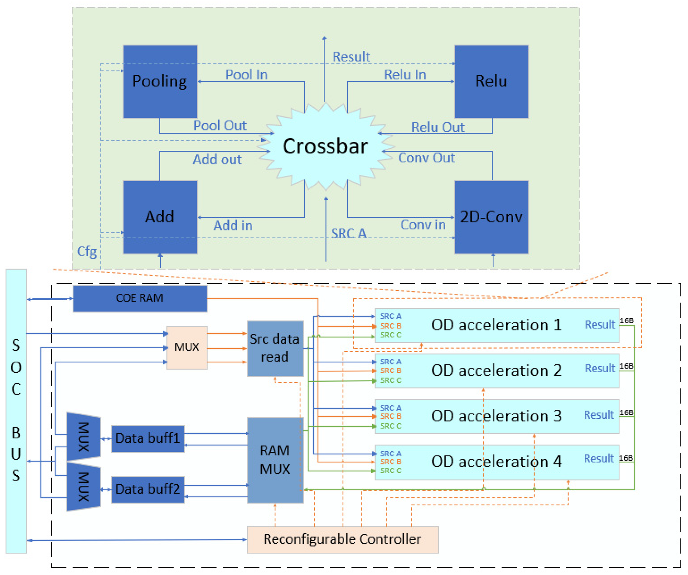
Figure 1 presents its structure.
As is shown in
Figure 1, the accelerator includes four OD acceleration units, wherein each OD acceleration unit includes four basic operation units and a configurable cross-switch. The four basic operation units are the main modules for acceleration, which contain algorithms such as convolution, pooling, etc. Moreover, the acceleration part of the CNN includes a source convolution kernel cache module (COE RAM) and ping-pong buffer blocks (data buff). Through the configuration of the cross-switch, data flows to different operation units. Thus, different OD algorithms can be accelerated. To enable other components in the system on chip (SOC) to configure parameters and access data from the acceleration unit, the entire accelerator is mounted on the system bus of the SOC.
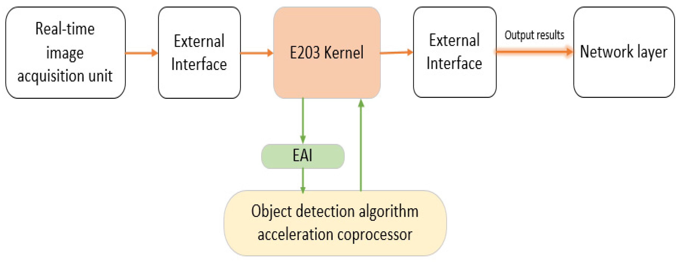
Figure 2 presents the data flow direction of the designed OD algorithm accelerator.
Based on the data flow direction shown in
Figure 2, the designed accelerator was a peripheral mounted on the ICB bus, and the E203 kernel was required to handle the movement of data. First, image data are required to move from the external interface to data storage and start processing by using the OD algorithm accelerator through the E203 kernel. Subsequently, the calculation results are returned from the accelerator to data storage through the E203 kernel, which are finally handed over to the network layer. It needs to pass through the data storage twice, before and after the processing algorithm. This results in an increase in the movement between data and unnecessary additional processing time. To further accelerate the algorithms’ speed, the designed accelerator is converted into a coprocessor.
Figure 3 shows the designed OD acceleration coprocessor.
The comparison presented in
Figure 2 and
Figure 3 indicates that, when the designed accelerator is connected to the processor through the EAI interface in the form of a coprocessor, the data movements are reduced. When the software is designed in the form of a coprocessor, programming is concise, and the code density is higher. Moreover, the power and unnecessary time consumed are saved. Therefore, the structure diagram in
Figure 1 was modified. According to the scalability of the RISC-V architecture and based on the Hummingbird E203 processor kernel, the design of the accelerated coprocessor for OD is completed through the EAI interface, and its hardware structure is shown in
Figure 4.
Compared with the accelerator in
Figure 1, the structure had an added EAI interface controller, a decoder, and a storage control unit. The newly added EAI interface controller was used to communicate with the main processor, receiving instructions, operands, and other types of information sent by the main processor through the request channel. Specifically, this channel returns the results of the coprocessor operation to the main processor through the feedback channel and writes data or sends read requests through the memory request channel. The data read from the memory are returned to the coprocessor through the memory feedback channel. The decoder is used to decode the coprocessor extension instructions and to configure the control register or introduce it to the memory access unit for memory access according to the type of instructions.
3.2. Convolution Circuit Design
As convolution operations are present in all mainstream OD algorithms, the magnitude of weights and bias parameters affects the overall network performance when computing a CNN, wherein a large number of high-precision floating-point operations exist. Convolutional operations account for a high proportion of the total time, where the computation of the convolutional part of the YOLO series algorithms even reaches more than 90%. Further, the convolutional layer is often followed by batch normalization and activation functions, which are used to accelerate model convergence and improve nonlinearity. The expression of batch normalization is presented in (1), where
yi represents the normalization result of the input data after batch standardization; μ represents the average value of the minimum batch data set during training, which can be obtained using (2); and
σ2 represents the variance of the minimum batch data set during training, which can be obtained using (3).
Here,
xi denotes the input data and ε represents a small positive number to prevent errors in the formula operation. Further,
γ and
β are the scale coefficient and the offset, respectively, which increase the stability of the standardized data. When training the YOLO algorithm model, the batch normalization calculation in the convolution circuit should also be optimized. Meanwhile, the parameter
in (1) is regarded as general. The external calculation is completed as a new
γ with
μ and
β weights passed into accelerators for the calculation, avoiding the accelerator directly calculating (1). Using this method, the division calculation and square calculation in the accelerator operation process are reduced, and the calculation process is accelerated. One of the two-dimensional matrices A of
n∗
n and a convolution kernel
W of size
m∗
m for the convolution operation can be expressed as:
Here, the volume of data loaded for the convolution operation between a n∗n matrix and a m∗m convolution kernel is m∗m∗(n − m + 1)∗(n − m + 1). A one-dimensional convolution can be regarded as the convolution of hte n∗1 two-dimensional matrix and m∗1 convolution kernel. The volume of data loaded is m∗(n − m + 1). However, almost all images are a two-dimensional convolution in the field of computer vision. Therefore, the one-dimensional convolution is not discussed separately.
In image processing, images are often represented as vectors of pixels, where
W2 denotes the length and width of the output feature map and
yd,i,j denotes elements of the
ith row and
jth column within the
dth output feature map. The length and width of the output feature map
W2 and those of the input feature map
W1 satisfy (5). Then, the elements on a single output feature map satisfy (6).
where
S and
P are the sliding step and the number of zero-complemented circles around the input feature map, respectively. Moreover,
C denotes the number of channels, m denotes the length and width of the convolution kernel, and
xc,i,j denotes the elements of the
ith row and
jth column within the input feature map of the
cth channel. Furthermore,
wd,c,a,b denotes the weights of the
ath row and
bth column of the
cth layer in the
dth convolution kernel. The bias size is
D, which is the same as the number of convolution kernels, and
bd denotes the
dth bias value. The number of channels on the output feature map is equal to that of convolution kernels
D. After
D convolution kernels and the input feature map are all operated according to the convolution formula, the N output feature maps are obtained for the subsequent processing level.
From the above basic analysis of the convolution process, data loading occurs many times in the convolution operation. Moreover, a large number of duplications exist in these data, especially the convolution operation, which accounts for a large proportion of the operation time of the entire algorithm. Thus, the R-CNN algorithm requires 2000 convolution operations; specifically, repeated loading of data from the memory leads to an increase in the number of operations and reduces the bus access bandwidth; hence, a large amount of power is consumed during the useless movement of data. Therefore, based on the improvement of the previous algorithm, optimization of the convolution operation can significantly improve the performance and resource utilization of the OD algorithm. Most resources of the convolution module are used for the design of the multiplier and adder, which mainly consume DSP and LUT resources.
Table 1 presents the resource losses of the multiplier and adder at different accuracy levels.
As is presented in
Table 1, unlike the floating-point 32-bit adder, the fixed-point 16-bit adder only consumes a small amount of LUT and does not consume DSP. Moreover, the resource consumption of the multiplier is greatly reduced. Therefore, the fixed-point calculation has great advantages in terms of ensuring data accuracy. In this study, a fixed-point number with fewer bits was used to replace the original floating-point number. To improve data reuse, bandwidth usage must be reduced, and data throughput should be increased. A convolutional operation circuit with a low data repetition rate was designed through the local cache unit.
Figure 5 presents the structure of the convolutional operation circuit.
Figure 5 shows the structure of the convolutional operation circuit. The loading unit of the picture source data was composed of a data reading unit and a cyclic queue cache unit. During the operation of OD algorithms, a picture is divided into a 5∗5 matrix and convoluted with a convolution kernel with a size of 3∗3 as an example.
Figure 6 presents the process of convolution data loading.
As is shown in
Figure 6, ∗ means convolution. when the convolution operation starts, the first read and write start pointers are placed in the first unit of the cyclic queue. Then, nine data are loaded from the memory to the cyclic queue position that corresponds to the write pointer. After the nine data are loaded, nine data are removed from the cyclic queue position that corresponds to the read pointer for operation. Furthermore, after the operation is completed, the read pointer is moved back three units. Note that, after each data load, the write pointer is moved back three units. Then, the nine data are read to perform the operation, and so on until the end of the process. This design of the convolutional operation circuit can reduce many repetitive data operations, and the optimization effect is most evident in the algorithm with excessive numbers of convolution layers. Taking two-dimensional convolution as an example, the amount of data loaded after optimization and the optimization rate η can be expressed as (7) and (8), respectively.
Many conventional networks are used in the OD algorithm (e.g., AlexNet, VGG-16, and ResNet). Considering the first layer of the YOLO network as an example, n = 448, M = 7, and η = 86.3%. Moreover, VGG-16 can be calculated, wherein the loading optimization rate of the convolution data of the first layer is 69.21% and that of the convolution output data of the last layer is 67.65%.
3.3. Design of the Pooling and Relu Circuits
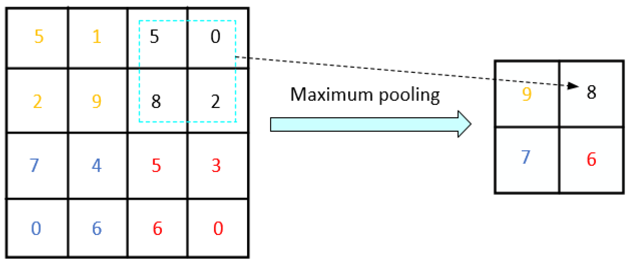
The pooling circuit down samples the input characteristic diagram to reduce the number of parameters and improve the calculation speed. Two common pooling layers exist: maximum and mean pooling layers. Maximum pooling is used to select the maximum value in the pooling window, whereas mean pooling is used to sum and average all the values in the pooling window. In particular, the calculation amount of maximum pooling is small, and the circuit structure is simple.
Figure 7 presents the principle of maximum pooling.
Maximum pooling is used in the ROI pool layer, which can convert features in any effective ROI region into a small feature graph with a fixed spatial range of
H∗
W, where
H and
W are super parameters. The pooling operation used in the reasoning and prediction process of the general OD algorithm is maximum pooling. Here,
ym,n represents the largest feature graph elements in the pooling domain, as expressed in (9).
Here,
Dm,n and
xi,j denote the range of feature map elements circled in the pooling domain within the input feature map and the input feature map elements within this pooling domain, respectively.
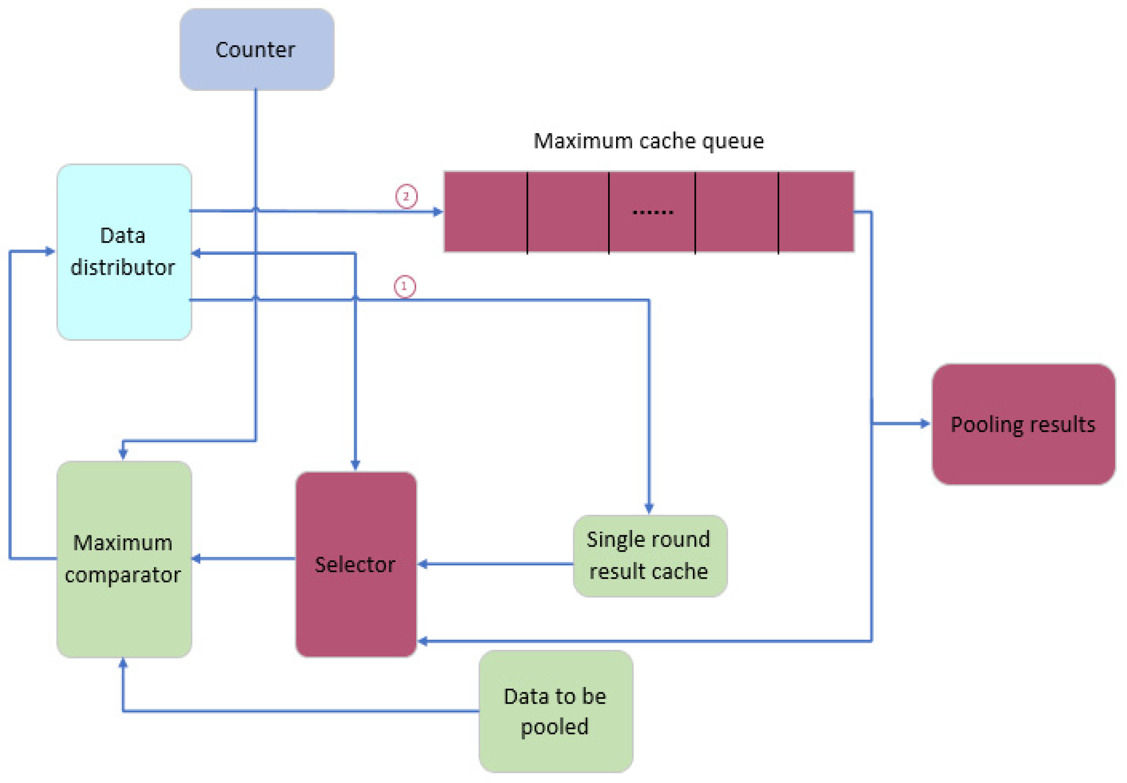
Figure 8 shows the designed pooling circuit according to the algorithmic characteristics of maximum pooling.
As is shown in
Figure 8, the designed pooling circuit structure comprises a counter, data distributor, maximum comparator, selector, maximum cache queue, and single round result cache. The counter is used to count the input data and control the entire circuit, and the circuit pools the input source matrix by row. Taking two-row matrices as an example, the maximum value is first calculated in the first row and stored in the maximum cache queue, and then waits for the input of the next row of data. When the second row of data is input, the maximum value of the previous row is removed from the cache queue. Thereafter, the maximum value of the corresponding position in the two rows is compared through the comparator.
In a CNN, to enhance its network performance, the excitation function of each neuron in a fully connected layer generally adapts a ReLU function, which is calculated as:
The ReLU function is found in CNN networks and in OD algorithms, such as the Faster R-CNN algorithm, which uses a basic Conv+ReLU+Pooling layer, and another one is YOLOv3, which also uses the ReLU function several times. Many OD algorithms also use an activation function. The designed ReLU circuit makes the basic network capable of fitting nonlinear classification problems. Further, the ReLU activation circuit makes positive and negative judgments on the input data, outputting directly if it is greater than 0, and outputting 0 if it is less than or equal to 0. The designed ReLU circuit reduces the move between data, and the design of this circuit forms a pipeline, which can achieve a variety of algorithm accelerations. Overall, the structure of the ReLU circuit can be simply understood; this is because the output is the input value when the input value is greater than 0, and the output is 0 when the input value is less than or equal to 0.
3.4. Design of the Control Switch Circuit
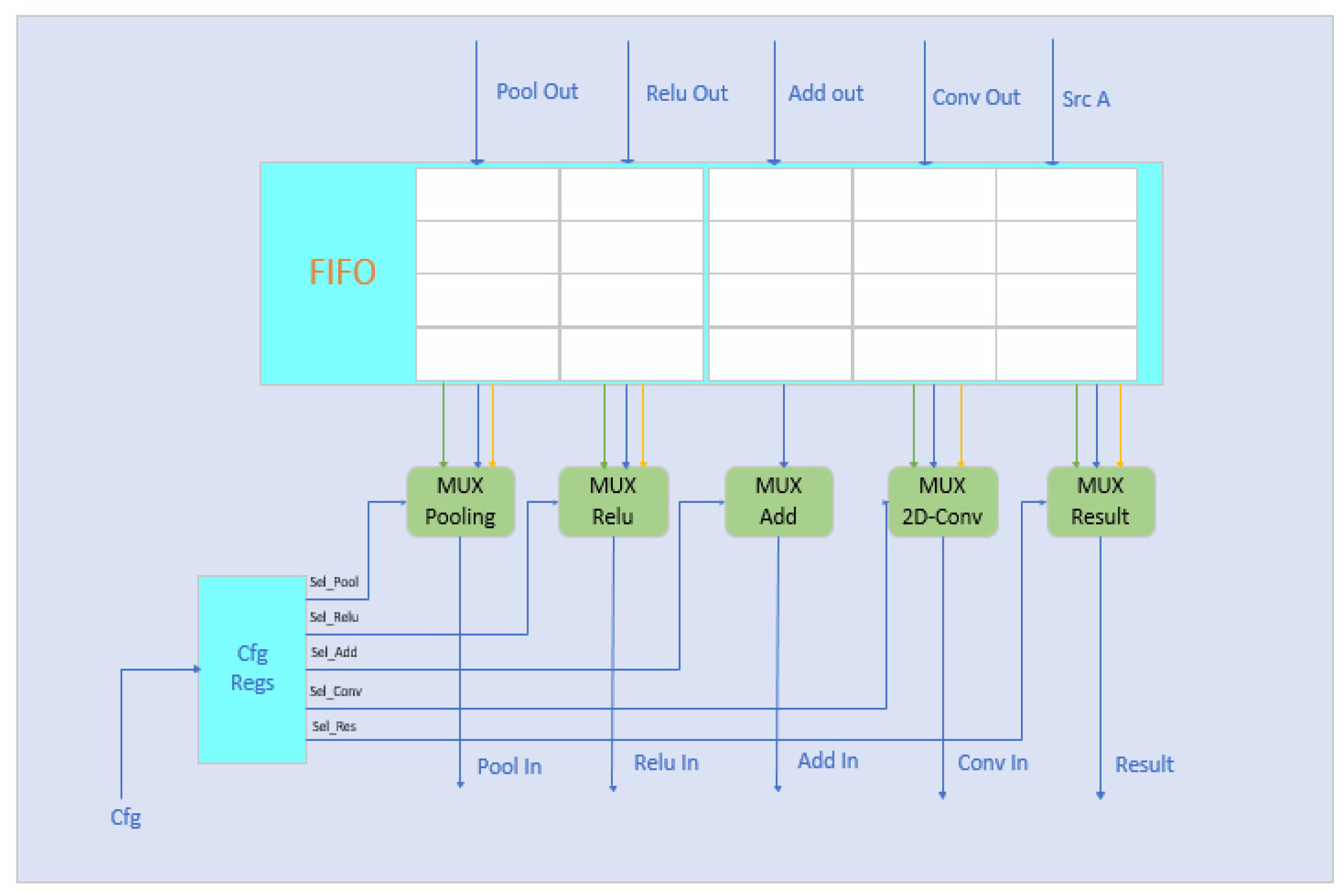
The design of the control switch circuit is key to achieving the acceleration of multiple OD algorithms. This circuit enables the input data flow in the OD ACC unit to pass through multiple calculation modules depending on the structure of the OD algorithm.
Figure 9 presents the structure diagram of the switch circuit design.
As is shown in
Figure 9, the circuit structure diagram of the designed control switch comprises a configuration register group, an input cache, and multiplexers. According to the structure of different OD algorithms, the input flows into the corresponding multiplexer, which selects the open data path, and then flows into different calculation modules to complete the control of different algorithms. Thereafter, YOLOv2 has a total of 22 convolution layers, 5 maximum pooling layers, 2 connection layers, and 1 reorganization layer. Excluding the reorganization layer, the green line in
Figure 9 represents the path of the YOLOv2 algorithm. In Faster R-CNN, the algorithm comprises convolution, pooling, and ReLU layers. Meanwhile, the yellow line in the figure represents the path of the Faster R-CNN algorithm. Different data paths are configured according to the principles of various algorithms to accelerate a variety of OD algorithms. Further, the system ICB bus is used for data transmission by the control switch circuit and the above calculation modules.
4. Instruction Design of the Accelerated Coprocessor in OD
From the hardware design of the accelerated coprocessor for OD, the next step was to complete the software environment development of the coprocessor. Based on the scalability of the RISC-V architecture, the coprocessor instructions were designed in this study, completing the establishment of the instruction compilation environment and library functions.
In this study, 15 types of extended instructions were designed for the acceleration coprocessor of OD algorithms for the custom instruction set (
Table 2).
The designed coprocessor instructions were divided into two categories according to their functions: coprocessor data loading and coprocessor configuration. Data loading class instructions were used to load convolution coefficients and the source matrix into the corresponding cache of the coprocessor. The function of the configuration instructions was to configure each functional module (e.g., the size of the input matrix, the size of the convolution kernel, and the configuration of OD algorithms to accelerate the working mode).
The calculation flow of the designed coprocessor instructions had five steps:
Step 1: Reset the acceleration circuit
Before using the coprocessor, it needs to be reset by using the od.reset instruction, which does not define the destination operand rd and source operands rs1 and rs2, but mainly realizes the function of clearing all registers in the coprocessor.
Step 2: Load the convolution kernel
When using the convolution module in the coprocessor, the coe cache is loaded with the convolution data from the memory by using the od.ld.ad instruction; here, the od.ld.ad instruction has two source operands: rs1 and rs2. Specifically, rs1 indicates that the convolution kernel data are in the register address coe mem addr, whereas rs2 indicates the length of the convolution kernel and the storage base address in the coe cache, where the convolution kernel length is 16-bits-high. Moreover, rs2[31:16] is the convolution kernel length, and rs2[15:0] is also the storage base address, which is the lower 16 bits. Here, the function of loading the convolution kernel coefficient length into the coe cache is mainly realized.
Step 3: Load the source matrix
The od.ld.ed instruction is used here to load the source matrix into the cache bank. It also has the destination operand rd and source operands rs1 and rs2. Specifically, rs1 and rs2 indicate the address of the source matrix in the register and the length of the source matrix and the storage base address in the coe cache, respectively. The length of the source matrix is 16-bits high. Moreover, rs2[31:16] is the length of the source matrix, and rs2[15:0] is also the storage base address, which is 16-bits low. Moreover, rd is not used as the destination register in this instruction, and this indicates the cache bank where the source matrix is stored. The od.load.ed instruction mainly implements the function of loading the source matrix into the cache bank.
Step 4: Configure the OD ACC parameters
When using the coprocessor configuration module, the following custom instructions are used to complete the configuration of different OD algorithms in various application scenarios. These include configuring the working mode instruction od.cfg.mo, input data location instructions od.cfg.ldl and od.cfg.ldm, result storage location instructions od.cfg.sdl and od.cfg.sdm, height and width of the input matrix instruction od.cfg.sms, convolution kernel parameter instructions od.cfg.cp and od.cfg.cb, pooled parameter instruction od.cfg.wh, and configuration matrix plus parameter instructions od.cfg.ada and od.cfg.ado. These configuration instructions are not expanded to describe the details of each instruction.
Step 5: Start the OD calculation
Finally, the computation is started by using the od.start instruction, which has no operands and enables the designed coprocessor to perform operations according to configuration parameters.
5. Experimental Results and Performance Analysis
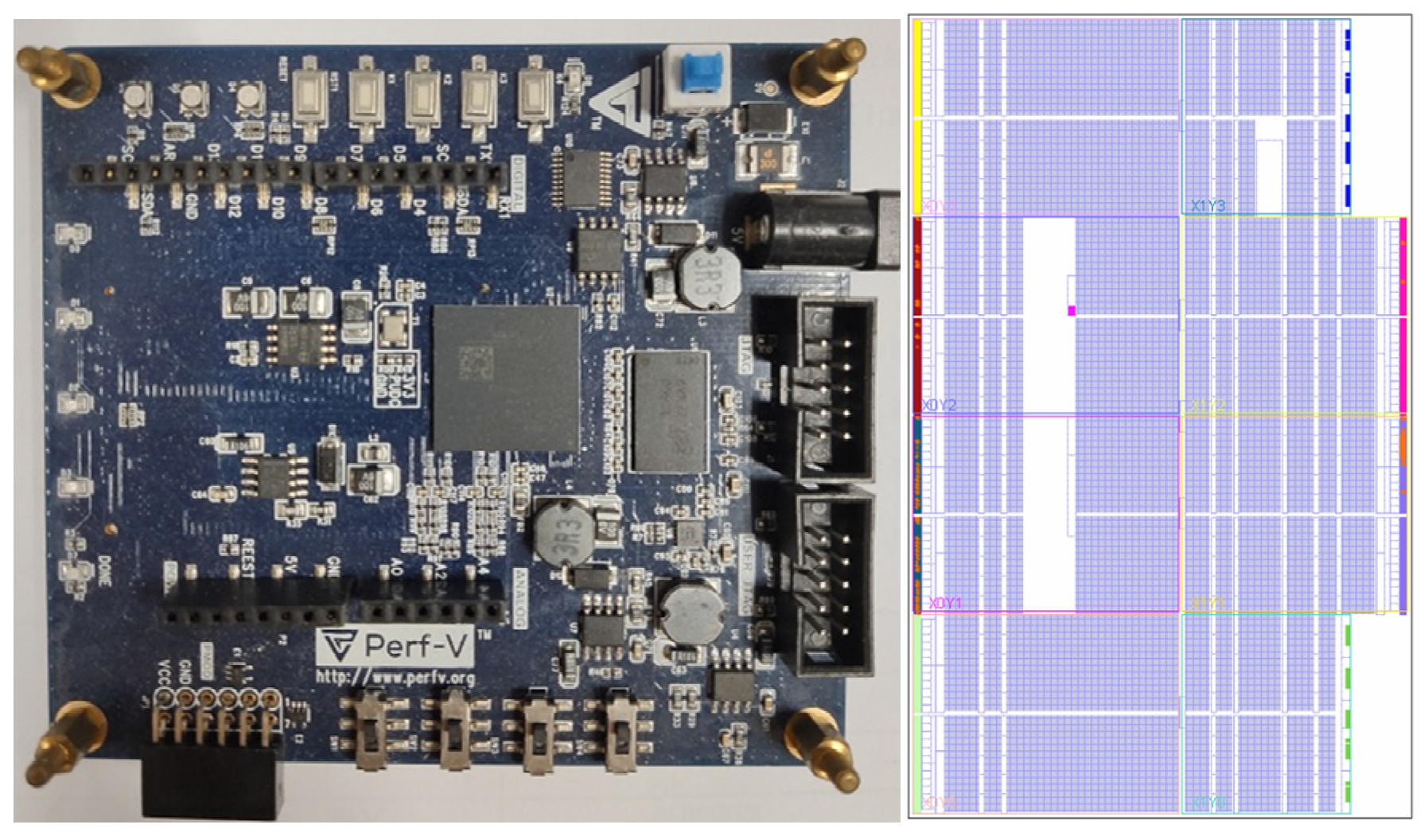
In this paper, the accelerated coprocessor of the OD algorithms was implemented on the xlinx platform. The SOC platform was built in Vivado 2018.3 to complete the design of the accelerated coprocessor architecture. This step was followed by FPGA circuit synthesis, implementation, functional simulation, and bitstream file generation for the E203 SoC with access to the coprocessor. The experimental environment and circuit layout diagram are shown in
Figure 10.
The basic unit for extracting feature maps in the OD algorithm is first analyzed to obtain the acceleration performance, which was implemented in this study by using two methods. These methods were implemented by using a standard instruction set and the designed custom instructions. The binary file generated by compiling the algorithm through the Testbench file was used as the input excitation for the entire E203 SoC. Additionally, the acceleration performance was determined through timing simulation and by counting and comparing the number of cycles executed by both methods. The results of this experiment are shown in
Table 3.
As is shown in
Table 3, the accelerated coprocessor had a speedup effect on all these operation units. The most obvious was the acceleration effect of the convolution, up to 6.94 times. Therefore, the convolution time can be greatly reduced when extracting the feature map. The acceleration effect of the matrix vector multiplication was also relatively high. The coprocessor was optimized for loading data and had a hardware multiplier. However, the multi-cycle multiplier and divider in the main processor were slower. Therefore, the performance must be effectively improved.
Subsequently, the performance of the coprocessor was verified by evaluating the resource loss and acceleration performance. Several representative OD algorithms were selected for testing, and the acceleration effects of the CPU and existing accelerators were compared to derive the final acceleration performance effect.
5.1. Resource Consumption Evaluation
As is presented in
Table 4, the designed coprocessor consumed 10091 LUT resources, accounting for 52.2% of the LUT resources of SOC, which was nearly three times lower than the amount of LUTs consumed by the accelerator in [
22]. Among them, DSP48E was mainly used for a fine-grained optimization strategy and configuration in a convolution module. Moreover, the designed coprocessor consumed a total of 23 DSP48E, making full use of the FPGA computing resources, which was much less than the 377 DSP48E consumed by the accelerator in [
7].
5.2. Resource Consumption Evaluation
The hardware acceleration of the YOLO and Faster R-CNN networks was chosen as an example to evaluate the coprocessor’s acceleration performance. First, a general-purpose CPU and two high-performance ARM CPUs were used as comparison objects, which have been introduced in relevant work wherein YOLOv3 itself uses a full convolution layer. Even the size modification of the feature graph was realized through the convolution layer. Faster R-CNN involves a shared convolution layer, RPN, ROI pooling, classification, and regression, and the ResNet-50 backbone network is used to detect Faster R-CNNs. The designed coprocessor had the best acceleration performance in terms of convolution operation. On average, The designed coprocessor had the best performance effect in terms of the YOLOv3 network. The results obtained through comparisons between a general-purpose CPU and a high-performance CPU are provided in
Table 5.
The comparison results in
Table 5 show that the designed acceleration coprocessor had the best computational performance of E203 SOC at the main frequency of 50 MHz, far exceeding the performance of a general-purpose CPU (Intel Core i7-6700K) and high-performance cores (Cortex-A7 and Cortex-A53).
Compared with other FPGA works, the accelerator proposed by Nakahara et al. [
7] had better computing performance, but it consumed far more FPGA on-chip resources than the designed coprocessor, and the resource consumption was high. Wai et al. [
23] proposed an Intel-based OpenCL method of accelerating matrices into blocks through general matrix multiplication and parallel multiplication, as well as the addition between blocks. However, this method required reordering the input feature map and convolution kernel parameters each time, which increased the preprocessing latency and complexity, thereby limiting the accelerator’s performance. The COCO dataset was used to train the YOLO network in this study.
Table 6 presents the comparison results.
Through this comparison with other FPGA accelerators, the acceleration coprocessor of OD algorithms, designed using a circuit multiplexing technique, was more balanced in terms of resource consumption and acceleration performance. Acceleration of YOLO and Faster R-CNN networks was realized with less resource consumption. From the calculation of DSP efficiency, unlike that in references [
24,
25], the efficiency of DSP in this study has been greatly improved. Moreover, the accelerated coprocessor is flexible and configurable, which can support different networks and has a greater practical value. However, the acceleration performance of the designed coprocessor for other mainstream OD algorithms (e.g., SSD and DSSD) is not described here. The acceleration performance graph is provided directly in
Section 5.3.
5.3. Acceleration Summary of Each OD Algorithm
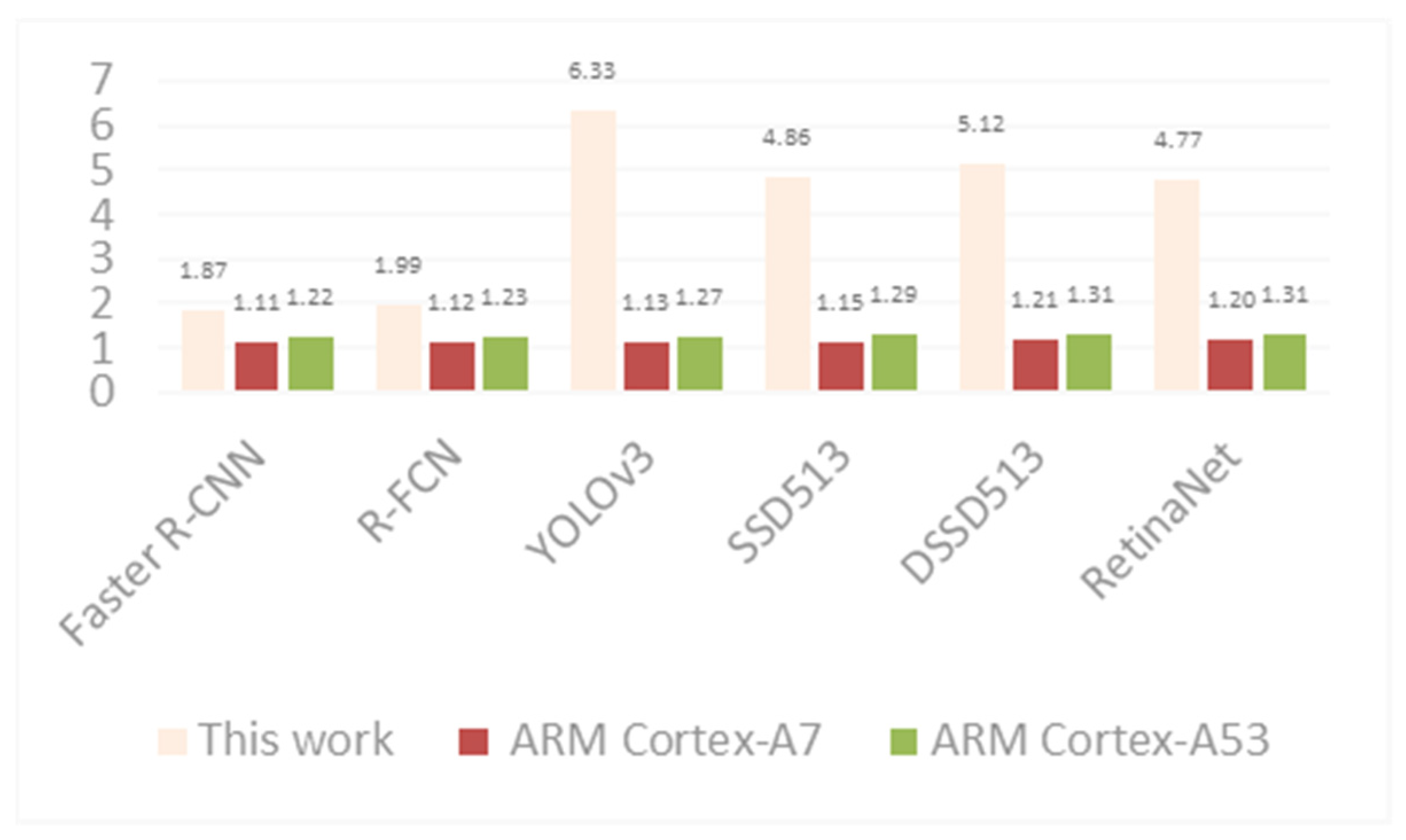
After training a variety of OD algorithms in the designed accelerated coprocessor, the acceleration ratios of representative algorithms were compared with those of high-performance CPUs on a general-purpose CPU basis (
Figure 11).
As is shown in
Figure 11, the designed coprocessor can accelerate various OD algorithms. Due to the characteristics of the algorithm network structure, the one-stage algorithm demonstrated excellent acceleration performance, and the acceleration performance of YOLOv3 was 6.33 times that of a general-purpose CPU.
The map and time for training six mainstream OD algorithms in
Figure 11 using the COCO dataset are presented in
Table 7.
To obtain the experimental results, the graph in [
26] was followed, and its framework was modified. Combining the map and time given in
Table 7, the performance of a high-performance CPU was compared with that of the designed accelerated coprocessor. Furthermore, the time was calculated according to the acceleration ratio presented in
Figure 11, and finally, a line graph was constructed.
Figure 12 presents the performance under different conditions. The performance of the designed accelerated coprocessor is indicated by a purple pentagram within the line graph.
6. Conclusions
In this study, a reconfigurable accelerator for OD on the processor system bus was investigated and designed for mainstream OD algorithms. Based on the accelerator, a new coprocessor capable of accelerating multiple OD algorithms was designed and implemented based on the kernel architecture of the open-source RISC-V processor E203. Additionally, the coprocessor’ structure was designed based on the design instructions, and the coprocessor instructions were encapsulated as function interfaces in the form of C language inline assembly. This study interconnected the basic arithmetic units in the OD algorithm with control switches, completing the configuration of different basic units of algorithms with custom library functions according to the algorithm structure. The designed coprocessor successfully reduced system power consumption while expediting the processing speed of multiple OD algorithms, addressing the poor performance and limited power consumption problems encountered by OD algorithms in practical applications. Regarding the results of the resource consumption and acceleration performance evaluation of the coprocessor, the coprocessor consumed one-third of the LUT compared with the results of existing studies and had excellent acceleration performance on basic unit convolution. Additionally, when comparing the coprocessor with those used in existing studies, the proposed accelerated coprocessor demonstrated better acceleration for the one-stage algorithm. In the future, the internal structure of the co-processor will be optimized to better reduce energy consumption and improve performance, and the contribution of this paper will be applied to a wider range of fields, such as big data security, etc.
