Abstract
Wake-up radio is a promising solution to reduce the energy wasted by mobile devices during an idle state. In this paper, we propose a new wake-up radio solution for 5G mobile devices based on a super-regenerative receiver characterized by its low cost and low power consumption and investigate how to build on the orthogonal frequency-division multiplexing (OFDM) modulation capability at the base station to generate optimal wake-up signals. After presenting the relevant features and limitations of super-regenerative receivers operating in different 5G New Radio (NR) frequency bands, we evaluate how the numerology, the number of resource blocks, and the quadrature amplitude modulation (QAM) scheme used affect the sensitivity of the super-regenerative wake-up receiver. The results show that a 256-QAM modulation scheme, together with the highest numerology values, achieves optimal receiver sensitivity with a minimal number of resource blocks, yielding higher duty cycle pulses that also facilitate symbol synchronization tasks.
1. Introduction
An important challenge in wireless networks is the limited battery life of wireless devices, i.e., the time that a full battery charge may last. For all battery-powered wireless devices, which range from smartphones to button-battery-powered temperature sensors, energy-efficient operation is critical. The Internet of Things (IoT) paradigm states that devices, such as sensors and actuators, should have a battery life of several years to meet minimum user intervention requirements.
Wireless communication is an important energy-consuming operation for wireless devices. In a large study carried out by monitoring 1520 smartphones, 51% of energy was found to be consumed by wireless communication components [1]. Accordingly, energy-efficient communication has been a major research target in recent years. The industrial community has also reacted to this challenge by incorporating energy-efficient communication approaches into wireless networking specifications, such as Wi-Fi (IEEE 802.11), LTE, 5G, and ZigBee (IEEE 802.15.4), along with the scientific community.
A technique that can significantly reduce the power consumption of wireless devices in an idle state is wake-up radio (WuR) [2,3,4,5,6,7]. In this paper, we propose a WuR solution for 5G New Radio (NR) devices based on the super-regenerative (SR) receiver (SRR). This receiver is characterized by a simple architecture and low power consumption [8,9]. In particular, we show that it is possible to take advantage of the orthogonal frequency-division multiplexing (OFDM) modulation capability available at the 5G base station (gNB) to generate optimal wake-up signals (WuSs). The best-suited numerologies, number of resource blocks, and modulation schemes are investigated. Previous work related to the application of SRR to OFDM communications can be found in [10].
2. Materials and Methods
2.1. Energy Consumption Reduction Strategies in Wireless Communications
A common approach to reducing the energy consumption of wireless communications is to reduce the energy waste caused by radio communications, which is largely due to idle listening and overhearing. Idle listening occurs when a node is in the reception state, but no communication is present in the channel, whereas overhearing occurs when a communication is received by a node, yet it is not intended for that node. The conventional solution proposed and applied for reducing idle listening is duty cycling, where the devices are put to sleep periodically. In this approach, they are not in a listening state permanently, and they wake up regularly to check for potential incoming packets. In other words, the device changes between the listening mode and sleep mode periodically. However, although the duty-cycling mechanism reduces idle listening, it does not fully remove it, still causing considerable energy waste. Moreover, duty cycling introduces a “sleeping” delay, since a communication that is destined to be received by the device has to wait until the device enters the listening mode.
2.2. Wake-Up Radio in 5G Communications
A communication paradigm that would reduce the energy waste caused by idle listening and that would achieve low communication latency is WuR, where a very-low-power secondary radio is used to wake up a sleeping device. In this way, wireless devices can remain in deep sleep mode and turn off the main radio unless woken up by remote triggering through WuR. Quantitative evaluations, e.g., [2], show that WuR is a more energy-efficient alternative to duty cycling. This is the reason why a task group (TGba) was founded under IEEE 802.11 to incorporate WuR into IEEE 802.11. The group recently (October 2021) published the developed standard. The study and the definition of a new WuS that is feasible for use in 5G NR is part of 3GPP Release 18 [11], since it has been proposed by several companies, e.g., [12,13]. So, there is no specific method defined for the verification of the integration of WuR solutions into 5G devices. Our paper is a step towards the possibility of the use of 5G modulation techniques for a wake-up receiver (WuRx).
The most important characteristics of a WuRx solution are its power consumption, sensitivity, and carrier frequency. Most WuRx studies focus on low carrier frequencies, which is not possible with the mobile network spectrum. Many WuRx hardware designs have been presented using either discrete components or integrated solutions, with most targeting sub-GHz frequencies and/or sensitivities between −50 and −70 dBm [14,15] to achieve sub-W level power consumption. However, since the network coverage is determined by the WuRx sensitivity, mobile networks need a WuR solution that achieves sensitivity levels as low as those of mobile devices (around −110 dBm).
2.3. The Super-Regenerative Receiver in 5G Wake-Up Radio
SRRs are characterized by their simplicity and low power consumption [8,9,16]. Other remarkable features include the following: low cost, suitability for integration, low operation voltage, and a short wake-up time. The most recent research activity focuses on their application in wireless sensor networks, including the Internet of Things and medical applications, the incorporation of digital calibration techniques, and their use in radar and mm-wave/terahertz systems [16,17,18,19,20,21,22,23]. On the other hand, new approaches and analysis techniques continue to appear [24,25].
SRRs can achieve ultra-low power consumption, offering better sensitivity compared to other WuR solutions [20,26,27]. Hence, they are excellent candidates for WuR, and we claim that they are suitable for use in 5G mobile devices. Figure 1 shows the concept proposed in this paper. The base station generates a WuS, which will be received and demodulated by the SR WuRx in the user equipment (UE). If the identification code (ID) included in the WuS matches the mobile device ID, then the WuRx triggers a hardware interrupt signal for the processor, which activates the main radio chip. With such a WuR solution, the processor and the main radio chip can be put into a deep sleep mode until a transmission addressed to that device occurs.
Figure 1.
Super-regenerative (SR) wake-up radio (WuR) concept. When the node identification code is received, an interrupt is triggered to activate the main radio chip.
5G NR is based on OFDM, which offers important flexibility at the gNB to generate a specific pulse waveform that is not only suitable but also optimal for the SR WuRx. The device ID is obtained upon the reception of M OFDM pulses or symbols.
A challenge to be addressed is the design of the WuS waveform, which should consider the 5G NR physical layer specifications, since the WuS will use the 5G spectrum, and the gNB should ideally multiplex the WuS with other types of 5G communication using the existing gNB hardware. The WuS should ideally be compliant with the physical layer of the 5G NR, and the WuRx must work at the mobile device sensitivity levels in accordance with the WuS. Note that the WuS should include synchronization and node ID information. According to the 5G NR standard, each gNB sends a synchronization signal burst set every 20 ms, which is confined to 5 ms. Hence, a time window of 15 ms is available every 20 ms to send a WuS without interference from other control signals. For instance, with a carrier spacing of kHz, 15 slots, i.e., 210 symbols, are available to send over the WuS, which should be enough for the SRR to synchronize and detect the ID to wake the main radio of the device. This paper focuses on proper WuS generation using gNB OFDM modulation.
2.4. Generation of Optimal Wake-Up Signals for the Super-Regenerative Wake-Up Receiver
2.4.1. Pulse Generation at gNB
In this section, we investigate the capability of OFDM modulation available at the gNB to generate an optimal WuS for the SR WuRx.
In 5G NR, time domain symbols are generated through the inverse fast Fourier transform (IFFT) of the blocks of 12 subcarriers, also known as resource blocks (RBs), where the subcarriers are separated by . 5G NR defines different numerologies with different subcarrier spacings, which can be seen in Table 1. An optimal pulse in the time domain can be generated with one or several RBs, the subcarriers of which have the proper amplitude and phase to reproduce the spectrum of the optimal pulse in the frequency domain. The modulation schemes defined for the data channels are the quadrature phase-shift keying (QPSK), 16-QAM, 64-QAM, and 256-QAM. As verified below, 256-QAM is the preferred scheme, since it allows more precise definition of the targeted spectrum. Hence, by injecting a suitable bit stream into the OFDM signal generation module, an arbitrary discrete spectrum can be generated using as many RBs as needed, with the only restriction being the discrete amplitude levels of the modulation scheme.
Table 1.
5G New Radio (NR)-transmission-supported numerologies for orthogonal frequency-division multiplexing (OFDM) that need to be met in the proposed solution.
The optimal pulse for an SRR is an RF pulse that typically has a Gaussian envelope. Hence, the spectrum of this pulse, which is centered on the carrier frequency, has a modulus that is also Gaussian and exhibits a fixed phase. In this work, the approximation to this Gaussian spectrum is generated by combining the points in the diagonal of the constellation (Figure 2) with an amplitude determined by the Gaussian function in the frequency domain. All points in the diagonal exhibit a fixed phase of /4, which results in a fixed phase in all subcarriers of the generated OFDM signal.
Figure 2.
Selected points (circled in blue) from the QPSK, 16-QAM, and 256-QAM constellations that are used to generate the wake-up signal (WuS).
It is worth emphasizing that the aim of the proposed SR WuRx is not to retrieve the bits coded on each subcarrier used to generate the OFDM symbol. In a conventional OFDM receiver, this usually requires taking N samples from the symbol and calculating a fast Fourier transform (FFT). For instance, an SR version of an OFDM receiver operating in this way is proposed in [10]. In this paper, our goal, instead, is to receive a pulse that is matched to the SR WuRx so that the signal-to-noise ratio at the receiver output is maximized. This implies taking a single sample of the OFDM symbol by generating one quench cycle during each symbol period. Each OFDM symbol carries part of the device ID, and the reception of M consecutive pulses (M OFDM symbols) allows for the retrieval of the entire ID.
2.4.2. Optimal Pulses for the SR WuRx
The super-regenerative oscillator (SRO) is the core of an SRR. The SRO is an RF oscillator that is periodically turned on and off under the control of an external periodic quench signal [8]. This generates a train of RF pulses at the output of the SRO separated by the quench period, where the peak amplitude (linear mode) or the width (logarithmic mode), as well as the phase, are determined by the small-amplitude RF signal injected into the SRO.
A characteristic of the SRO is that it is sensitive to the RF input signal during a relatively small fraction of the quench period, . Thus, the receiver can be understood as a system that periodically samples the input signal amplitude and phase. According to the proposal presented in Figure 1, a single quench cycle must be generated during each OFDM symbol period, , so that a single sample of this pulse carrying a single or several ID bits is taken. The SRO sensitivity periods are characterized by the sensitivity function . This function defines the optimal input pulse waveform, typically a Gaussian function when the SRO operates in the so-called slope-controlled state, for which the receiver behaves as a matched filter [9].
A key point of this study is to evaluate the duration of the sensitivity period of the SRO with respect to the OFDM symbol duration. The model presented in [8] was used to evaluate the effective duration of the sensitivity period, . It was found that, under typical operation conditions, the duration ranges from 10% of , which is typical of low quench frequencies, to 20% of , which is typical of high quench frequencies.
A second key point is the range of suitable quench frequencies for the SRO. The aforementioned model was also used to evaluate this range, which is determined by the ratio of the oscillation frequency, , to the quiescent quality factor of the SRO, . represents the Q factor of the frequency-selective network (resonant circuit) of the SRO [8]. For instance, for = 10, the range of suitable quench frequencies in the linear mode and with a fixed peak gain of dB is approximately between and . The lower limit is imposed by the transition from the super-regenerative to the regenerative mode of operation, whereas the upper limit is imposed by the hangover [8]. This range can be expanded, to some extent, with the use of precision quench techniques while also in the logarithmic mode. The range limits turn out to be inversely proportional to . As an example, when taking one of the bands available in 5G NR, say GHz, the suitable quench frequencies for = 10 range from 0.9 MHz to 36 MHz ( ns s). Table 2 summarizes the maximum quench period and the corresponding sensitivity period duration, assuming = 0.1 , for different frequency bands available in 5G and different values for . A quality factor of 10 can be achieved with integrated inductors, while values ranging from 30 to 100 can be achieved with external inductors or resonators (the viability of each depends on the operating frequency). As can be observed, in most cases, the maximum quench period is smaller than any of the available symbol periods in Table 1.
Table 2.
Duration of the sensitivity period of the super-regenerative oscillator (SRO) for different maximum quench period values. The effective duration of the OFDM pulse must be close to .
From Table 1 and Table 2, it can be concluded that in order to adapt the quench cycle to the OFDM symbol period, (a) the highest values of and the lowest frequency of 700 MHz are preferable, as they allow the longest quench periods, and (b) the highest numerology values are best suited because they provide the shortest symbol periods.
Table 3 provides the ratio of to . For the cases where the maximum in Table 2 is smaller than , it is assumed that inactive quench periods are included between active quench periods to match whole OFDM symbol periods (see Section 2.5). The low values in Table 3 mean that the optimal pulse for the SR WuRx must exhibit a low duty cycle, which also entails a high peak-to-average power ratio. Therefore, in line with the above conclusions, a higher and higher numerologies are preferable as they increase the duty cycle.
Table 3.
Sensitivity period-to-OFDM symbol period ratio: at = 700 MHz.
2.5. A Case Study
Next, in order to assess the performance achieved by the generated OFDM pulses, we present the analysis results obtained by using Matlab by considering the numerology values from = 0 to = 4, regardless of whether these values are available in the specific frequency bands or implementations. We used the model presented in [8], which is based on the analytical solution to the differential equation that describes the dynamics of the SRO.
The SRO considered is characterized by the parameters presented in Table 4. The lowest frequency of 700 MHz was chosen, along with an intermediate quality factor: . The quench waveform is a sawtooth, which is known to produce a wider sensitivity function. Figure 3 shows the quench waveform (i.e., the damping function, ), the sensitivity function, and the pulse generated in the SRO for .
Table 4.
SRO parameters in the case study.
Figure 3.
Damping function (top) and signal generated at the SRO (bottom) in the case study for = 2 ( s, active quench period s). The dashed line represents the sensitivity function of the SRO.
For , the active quench period is limited by the values presented in Table 2, and, therefore, the inactive periods must be added to match the whole OFDM symbol period (Figure 3). For and , the limits presented in Table 2 allow for an active quench period that is equal to or close to the OFDM symbol period. In the following results for these two latter cases, was set to be equal to the symbol period, excluding the cyclic prefix subperiod and keeping the quench inactive during said subperiod, since no useful signal is expected at the input.
In order to describe the computation procedure carried out, let us consider the generated OFDM pulse expressed as
where , N is the total number of subcarriers, and , , and are the amplitude, frequency, and phase associated with each subcarrier, respectively. represents the instantaneous amplitude and the instantaneous phase of the pulse taking the center carrier frequency as a reference. The subcarrier frequencies are
The complex coefficients associated with each subcarrier are the points chosen from the constellation in Figure 2; therefore, and represents the magnitude of the point in the constellation closest to the magnitude of the spectrum of the optimal pulse to be approximated,
where is the number of points selected from the constellation (i.e., 1 for QPSK, 2 for 16-QAM, 4 for 64-QAM, and 8 for 256-QAM), and is the standard deviation of the optimal pulse spectrum (Table 4), which is also Gaussian. By adding the complex signals associated with the different subcarriers, we obtain
When evaluated at the instants , Equation (4) takes the form of an IFFT. This equation yields a real function since the spectrum to be approximated, a Gaussian bell, is symmetric with respect to . Equation (1) represents the input signal of the SRO and has the form
where V is the peak amplitude, and is a normalized function describing the envelope of the RF oscillation. Assuming that the SRO is tuned to the received carrier frequency , the peak amplitude of the RF oscillation generated at the ouput of the SRO in the linear mode is given by [8]:
where is the maximum amplification of the frequency-selective network of the SRO, is the super-regenerative gain, and is the regenerative gain. According to [8], while and are independent of the input signal, depends on the shape of ,
where is the sensitivity function of the SRO, and and stand for the initial and the final instants, respectively, of the quench period. In the following results, in order to properly compare the performances offered by the different pulses generated, the peak amplitude at the input is set to provide a fixed pulse energy, E:
The above expressions can be particularized to the case in which the input pulse is matched to the SRO, i.e., when . This allows for computing the output signal loss (in decibels) introduced by a specific OFDM pulse with respect to the matched pulse,
which, after the replacement of Equations (8) and (9) and considering the same pulse energy for the matched and the OFDM pulses, yields
The variable L provides a measure of the similarity between the generated OFDM pulse and the optimal pulse, with lower values being better. This magnitude also represents the output signal-to-noise ratio loss and the receiver sensitivity loss due to pulse mismatch.
The results that appear in the next figures show the OFDM symbol in the time domain (Equation (1)) for different sets of . Each set comes from a different combination of the parameter , which determines the subcarrier spacing (, Table 1); the number of RBs, which determines the total number of subcarriers (N = 12 × number of RBs); and the modulation scheme, which determines the quantization error in the magnitude of (Equation (3)). These sets of were introduced into Equation (4) to numerically compute the amplitude in Equation (1).
3. Results
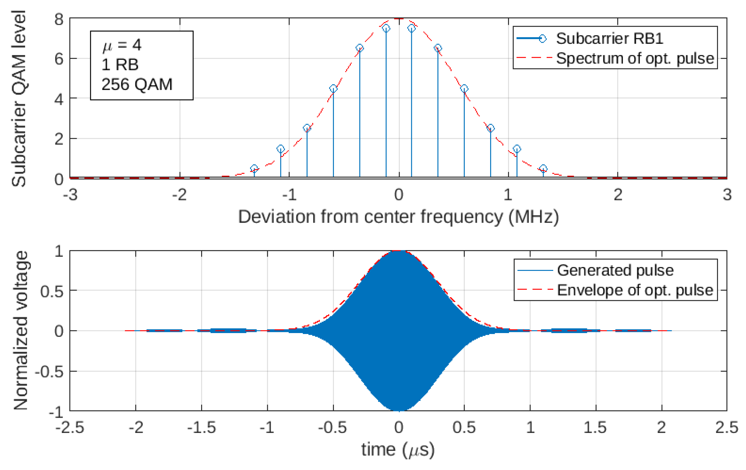
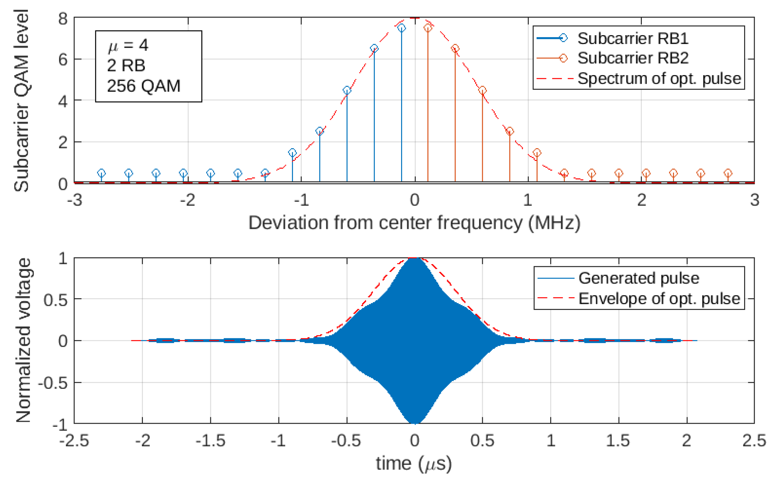
3.1. Influence of Numerology and the Number of Resource Blocks
In the subsequent figures, the subcarrier distribution in the frequency domain and the corresponding pulse generated in the time domain are plotted for different numerologies and different number of RBs used. The frequency scale is fixed, whereas the time scale varies to accommodate a whole OFDM symbol period. The dashed lines indicate the spectrum and the envelope of the optimal pulse.
Figure 4 shows the results for using one RB and the 256-QAM modulation scheme. The results for are qualitatively similar with half subcarrier spacing and are not included in the graphs. As is shown, the constant amplitude subcarriers cover a small portion of the spectrum, resulting in a sync pulse in the time domain. This pulse exhibits several side lobes and is considerably wider than the optimal pulse. Clearly, this is a sub-optimal situation, and a greater number of RBs is required to cover a significant portion of the Gaussian bell. Figure 5 shows that the result with four RBs significantly improves, and the generated pulse matches the optimal pulse very well, with negligible side lobes.
Figure 4.
Subcarrier distribution in the frequency domain (top) and the corresponding OFDM symbol in the time domain (bottom) for = 1, one resource block (RB), and 256-QAM. There is a poor match with the optimal pulse.
Figure 5.
Subcarrier distribution in the frequency domain (top) and the corresponding OFDM symbol in the time domain (bottom) for = 1, four RBs, and 256-QAM. There is a good match with the optimal pulse, which exhibits a low duty cycle.
Figure 6 presents the results for . Although the OFDM symbol period has been reduced by half, the active quench period is exactly the same as in the previous case. Therefore, the sensitivity period, the optimal pulse, and the corresponding Gaussian bell in the spectrum remain exactly the same. As is shown, two RBs are enough to obtain a satisfactory result.
Figure 6.
Subcarrier distribution in the frequency domain (top) and the corresponding OFDM symbol in the time domain (bottom) for = 2, two RBs, and 256-QAM. There is a good match with the optimal pulse, which exhibits a higher duty cycle.
Figure 7 shows the results for . The optimal pulse is exactly the same as before; therefore, a single RB is enough to obtain the desired result.
Figure 7.
Subcarrier distribution in the frequency domain (top) and the corresponding OFDM symbol in the time domain (bottom) for = 3, one RB, and 256-QAM. There is a good match with the optimal pulse, which exhibits an even higher duty cycle.
Figure 8 shows the results for . In this case, the active quench period can be reduced to match the symbol period. This results in a narrower pulse in the time domain and a wider Gaussian bell in the frequency domain. One RB is enough to generate the optimal pulse. Figure 9 presents what happens when two RBs are used for this value of . As there are several subcarriers outside of the significant values of the Gaussian bell and the constellation does not allow zero-amplitude points to be assigned, the pulse in the time domain differs from the optimal one. Hence, using an excessive number of RBs is counterproductive, a phenomenon that is also observed for all other numerologies.
Figure 8.
Subcarrier distribution in the frequency domain (top) and the corresponding OFDM symbol in the time domain (bottom) for = 4, one RB, and 256-QAM. There is a good match with the optimal pulse, which exhibits a maximum duty cycle.
Figure 9.
Subcarrier distribution in the frequency domain (top) and the corresponding OFDM symbol in the time domain (bottom) for = 4, two RBs, and 256-QAM. The pulse differs from the optimal one due to an excessive number of resource blocks.
Table 5 summarizes the output signal loss, L, in dB relative to the output with an optimal SRO pulse (Equation (11)) due to pulse mismatching for different numerologies and different number of RBs used. The pulse energy was normalized in all cases to make the comparison. As the table reveals, several combinations of these parameters achieve a performance close to the optimum.
Table 5.
Output signal loss, L, in dB relative to an output with an optimal SRO pulse (Equation (11)). Modulation scheme: 256-QAM.
It is worth pointing out that, although the optimal pulse can be approximated well in all numerologies, the duty cycle of the pulse is considerably lower for lower values of . Hence, to reduce the peak-to-average power ratio and to also improve symbol synchronization, the pulse in Figure 8 with using one RB can be considered the best option for the SR WuRx. Choosing with one RB may be acceptable as well.
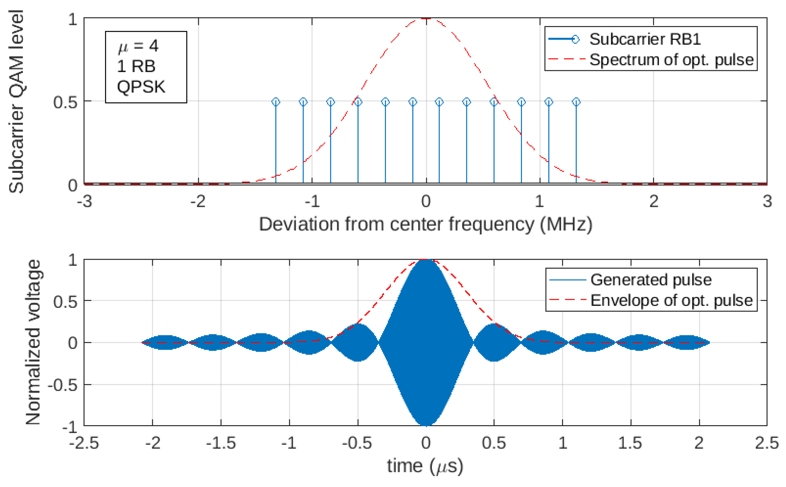
3.2. Influence of the Modulation Scheme
Figure 10 and Figure 11 show how the shape of the pulse degrades with 16-QAM and QPSK modulation, respectively. They confirm that 256-QAM is the best solution, as predicted, as it allows for better approximations of the shape of the desired spectrum.
Figure 10.
Subcarrier distribution in the frequency domain (top) and the corresponding OFDM symbol in the time domain (bottom) for = 4, one RB, and 16-QAM. Several significant secondary lobes appear.
Figure 11.
Subcarrier distribution in the frequency domain (top) and the corresponding OFDM symbol in the time domain (bottom) for = 4, one RB, and QPSK. The pulse shape is degraded compared to that obtained for the other modulation schemes.
Table 6 provides the output signal loss, L, in dB relative to the output with an optimal SRO pulse (Equation (11)) for different modulation schemes. As expected, the performance is degraded with a reduction in the number of points in the constellation, although the differences are not dramatic.
Table 6.
Output signal loss, L, in dB relative to the output with an optimal SRO pulse (Equation 11).
In summary, the best results for optimal WuS generation were obtained for the 256-QAM modulation scheme and the highest numerology values, which also require fewer resource blocks to cover the spectrum of the optimal pulse.
4. Discussion
A wake-up radio solution for 5G devices based on a low-cost and low-power super-regenerative receiver was proposed. We showed that, by taking advantage of the OFDM flexibility available at the 5G base station, it is possible to generate optimal pulses for the receiver.
On one hand, this study concludes that super-regenerative oscillators with high-quality factors are preferable. On the other hand, the 256-QAM modulation scheme, along with the highest numerologies, is best suited for the wake-up receiver, which also requires a minimum number of resource blocks and facilitates symbol synchronization. It should be noted that, unlike other wake-up radio systems, and to the extent that optimal signals are generated for the receiver, it will be possible to operate this system as a matched filter, achieving sensitivities similar to those obtained by the main radio of 5G devices.
One possible line of future research includes considering the restrictions imposed by the 5G standard, especially those related to the physical layer. The practical performance achieved by receiver implementations operating in real environments should also be evaluated.
Author Contributions
Conceptualization, F.X.M.-G., F.d.-Á.-L. and I.D.; methodology, F.X.M.-G. and F.d.-Á.-L.; software, F.X.M.-G.; validation, F.X.M.-G.; formal analysis, J.B.-D.; investigation, F.X.M.-G., F.d.-Á.-L. and J.B.-D.; resources, F.X.M.-G. and I.D.; writing—original draft preparation, F.X.M.-G.; writing—review and editing, F.d.-Á.-L. and P.P.-S.; visualization, F.X.M.-G.; supervision, P.P.-S.; project administration, F.X.M.-G. and I.D.; funding acquisition, F.X.M.-G. and I.D. All authors have read and agreed to the published version of the manuscript.
Funding
This research was funded by MCIN/AEI/10.13039/501100011033 and by “ERDF A way of making Europe”, grant number PID2021-128166OB-I00, and by the Generalitat de Catalunya grant Consolidated Research Groups, SGR 01041 (RIIS).
Data Availability Statement
Data are contained within the article.
Acknowledgments
The authors thank Pau de las Heras for his contributions to the validation of the results.
Conflicts of Interest
The authors declare no conflict of interest.
References
- Chen, X.; Ding, N.; Jindal, A.; Hu, Y.C.; Gupta, M.; Vannithamby, R. Smartphone Energy Drain in the Wild: Analysis and Implications. SIGMETRICS Perform. Eval. Rev. 2015, 43, 151–164. [Google Scholar] [CrossRef]
- Oller, J.; Demirkol, I.; Casademont, J.; Paradells, J.; Gamm, G.U.; Reindl, L. Has Time Come to Switch From Duty-Cycled MAC Protocols to Wake-Up Radio for Wireless Sensor Networks? IEEE/ACM Trans. Netw. 2016, 24, 674–687. [Google Scholar] [CrossRef]
- McCormick, D.K. Preview: IEEE Technology Report on Wake-Up Radio: An Application, Market, and Technology Impact Analysis of Low-Power/Low-Latency 802.11 Wireless LAN Interfaces; IEEE Press/Standards Information Network: Piscataway, NJ, USA, 2017; pp. 1–11. [Google Scholar] [CrossRef]
- Fumtchum, C.A.; Hutu, F.D.; Tsafack, P.; Villemaud, G.; Tanyi, E. Towards a Battery-Free Wake-up Radio. Electronics 2021, 10, 2449. [Google Scholar] [CrossRef]
- Mercier, P.P.; Calhoun, B.H.; Wang, P.H.P.; Dissanayake, A.; Zhang, L.; Hall, D.A.; Bowers, S.M. Low-Power RF Wake-up Receivers: Analysis, Tradeoffs, and Design. IEEE Open J. Solid-State Circuits Soc. 2022, 2, 144–164. [Google Scholar] [CrossRef]
- Ketata, I.; Ouerghemmi, S.; Fakhfakh, A.; Derbel, F. Design and Implementation of Low Noise Amplifier Operating at 868 MHz for Duty Cycled Wake-Up Receiver Front-End. Electronics 2022, 11, 3235. [Google Scholar] [CrossRef]
- Zhang, T.; Afshang, M.; Mozaffari, M.; Wang, Y.P.E. Toward Zero-Energy Devices: Waveform Design for Low-Power Receivers. IEEE Commun. Lett. 2023, 27, 2038–2042. [Google Scholar] [CrossRef]
- Moncunill-Geniz, F.; Pala-Schonwalder, P.; Mas-Casals, O. A generic approach to the theory of superregenerative reception. IEEE Trans. Circuits Syst. I Regul. Pap. 2005, 52, 54–70. [Google Scholar] [CrossRef]
- Moncunill-Geniz, F.X.; Pala-Schonwalder, P.; Dehollain, C.; Joehl, N.; Declercq, M. An 11-Mb/s 2.1-mW Synchronous Superregenerative Receiver at 2.4 GHz. IEEE Trans. Microw. Theory Tech. 2007, 55, 1355–1362. [Google Scholar] [CrossRef]
- Moncunill-Geniz, F.X.; Bonet-Dalmau, J.; Del Águila Lopez, F.; Demirkol, I.; Palà-Schönwälder, P. Super-Regenerative Receiver for OFDM Communication. In Proceedings of the 2022 IEEE International Symposium on Circuits and Systems (ISCAS), Austin, TX, USA, 28 May–1 June 2022; pp. 1843–1847. [Google Scholar] [CrossRef]
- 3GPP. Study on Low-Power Wake-Up Signal and Receiver for NR. Technical Report 38.869, Release 18, 3GPP, Specification Series. 2023. Available online: https://www.3gpp.org/dynareport?code=38-series.htm (accessed on 3 November 2023).
- Apple. On Rel-18 Low Power Wake Up Radio; Technical Report RP-212367, 3GPP, RAN Meeting #93-e; Apple: Los Altos, CA, USA, 2021. [Google Scholar]
- Ericsson. Motivation for Rel-18 WI on Enhanced RedCap; Technical Report RWS-210313, 3GPP, TSG RAN Rel-18 Workshop; Ericsson: Stockholm, Sweden, 2021. [Google Scholar]
- Bdiri, S.; Derbel, F.; Kanoun, O. An 868 MHz 7.5 µW wake-up receiver with −60 dBm sensitivity. J. Sensors Sens. Syst. 2016, 5, 433–446. [Google Scholar] [CrossRef]
- Jiang, H.; Wang, P.H.P.; Gao, L.; Sen, P.; Kim, Y.H.; Rebeiz, G.M.; Hall, D.A.; Mercier, P.P. 24.5 A 4.5nW wake-up radio with −69 dBm sensitivity. In Proceedings of the 2017 IEEE International Solid-State Circuits Conference (ISSCC), San Francisco, CA, USA, 5–9 February 2017; pp. 416–417. [Google Scholar] [CrossRef]
- Fu, X.; El-Sankary, K.; Ge, Y.; Yin, Y.; Truhachev, D. A Blind Background Calibration Technique for Super-Regenerative Receivers. IEEE Trans. Circuits Syst. II Express Briefs 2022, 69, 344–348. [Google Scholar] [CrossRef]
- Kong, F.; Ghovanloo, M.; Durgin, G.D. An Adaptive Impedance Matching Transmitter for a Wireless Intraoral Tongue-Controlled Assistive Technology. IEEE Trans. Circuits Syst. II Express Briefs 2020, 67, 240–244. [Google Scholar] [CrossRef]
- Yuan, Y.; Wu, C.T.M. Super-Regenerative Oscillator Integrated Metamaterial Leaky Wave Antenna for Multi-Target Vital Sign and Motion Detection. IEEE J. Electromagn. Microwaves Med. Biol. 2022, 6, 238–245. [Google Scholar] [CrossRef]
- Pekcokguler, N.; Dundar, G.; Dehollain, C. A Novel Area Efficient Inductorless Super-Regenerative Receiver Front-End for Medical Brain Implants. In Proceedings of the 2023 19th International Conference on Synthesis, Modeling, Analysis and Simulation Methods and Applications to Circuit Design (SMACD), Funchal, Portugal, 3–5 July 2023; pp. 1–4. [Google Scholar] [CrossRef]
- Yin, Y.; Fu, X.; El-Sankary, K. A PVT-Robust Super-Regenerative Receiver with Background Frequency Calibration and Concurrent Quenching Waveform. Electronics 2019, 8, 1119. [Google Scholar] [CrossRef]
- Hahn, L.; Vossiek, M.; Carlowitz, C. A Subharmonic Super-Regenerative FMCW Radar With Improved Intermodulation Efficiency for Applications Beyond Cut-Off Frequency. IEEE Trans. Microw. Theory Tech. 2023, 1–15. [Google Scholar] [CrossRef]
- Ghaleb, H.; Carlowitz, C.; Fritsche, D.; Stärke, P.; Protze, F.; Carta, C.; Ellinger, F. A 180-GHz Super-Regenerative Oscillator With up to 58 dB Gain for Efficient Phase and Amplitude Recovery. IEEE Trans. Microw. Theory Tech. 2020, 68, 2011–2019. [Google Scholar] [CrossRef]
- Garay, E.F.; Munzer, D.J.; Wang, H. A 150 GHz Lens-Free Large FoV Regenerative 2 × 2 Transceiver Array with 31Bidirectional Peer-to-Peer Link. IEEE J. Solid-State Circuits 2022, 57, 2102–2113. [Google Scholar] [CrossRef]
- Hernández, S.; Suárez, A. Envelope-Domain Analysis and Modeling of Super-Regenerative Oscillators. IEEE Trans. Microw. Theory Tech. 2018, 66, 3877–3893. [Google Scholar] [CrossRef]
- Sancho, S.; Hernández, S.; Suárez, A. Noise Analysis of Super-Regenerative Oscillators in Linear and Nonlinear Modes. IEEE Trans. Microw. Theory Tech. 2019, 67, 4955–4965. [Google Scholar] [CrossRef]
- Kim, S.J.; Lee, D.; Lee, K.Y.; Lee, S.G. A 2.4-GHz Super-Regenerative Transceiver With Selectivity-Improving Dual Q-Enhancement Architecture and 102-μW All-Digital FLL. IEEE Trans. Microw. Theory Tech. 2017, 65, 3287–3298. [Google Scholar] [CrossRef]
- Fuketa, H.; O’uchi, S.; Matsukawa, T. A 0.3-V 1-μW Super-Regenerative Ultrasound Wake-up Receiver with Power Scalability. IEEE Trans. Circuits Syst. II Express Briefs 2017, 64, 1027–1031. [Google Scholar] [CrossRef]
Disclaimer/Publisher’s Note: The statements, opinions and data contained in all publications are solely those of the individual author(s) and contributor(s) and not of MDPI and/or the editor(s). MDPI and/or the editor(s) disclaim responsibility for any injury to people or property resulting from any ideas, methods, instructions or products referred to in the content. |
© 2023 by the authors. Licensee MDPI, Basel, Switzerland. This article is an open access article distributed under the terms and conditions of the Creative Commons Attribution (CC BY) license (https://creativecommons.org/licenses/by/4.0/).