Abstract
Development of a general-purpose PLC based on a typical dual-core processor as a hardware platform is presented. The cores run two cooperating projects involving data exchange through shared memory. Such a solution is equivalent to a single-core PLC running two tasks by means of a real-time operating system. Upgrading to a typical programming tool involves defining which of the global variables are shared, and whether a variable in a particular core is read-from or written-to the shared memory. Extensions to core runtimes consist of read-from at the beginning of the scan cycle and write-to at the end, and of an algorithm for protecting the shared memory against access conflicts. As an example, the proposed solution is implemented in an engineering tool with runtime based on a virtual machine concept. The PLC prototype is based on a heterogeneous ARM dual-core STM32 microcontroller running different projects. The innovation in the research lies in showing how to run two projects in a dual-core PLC without using an operating system. Extension to multiple projects for a multi-core processor is can be accomplished in a similar manner.
1. Introduction
The increasing complexity of industrial plants imposes growing requirements on the corresponding automation systems in terms of processing power, real-time performance, and safety. At the same time, the limitations of chip technology indicate the inability to increase processing power simply by increasing the processor frequency without an equivalent increase in energy consumption. The requirement of increased processing power can only be met by multi-core CPUs where limitations are considerably milder. Hence, the evolution of embedded systems is going in that direction, and some manufacturers of PLCs already provide multi-core solutions. PLCnext from Phoenix Contact, Telford, UK [1] involving a dual-core ARM Cortex-A9 processor and the Embedded PC series from Beckhoff [2], also with a dual-core ARM Cortex-A53, are examples in the medium performance range. Programing languages and runtime execution environments comply with the IEC 61131-3 standard [3].
Currently, 70% of embedded systems use processors built around the ARM architecture (Advanced RISC Machine) [4], which is appreciated for its high performance, low energy consumption, and low price. The mass implementation of this architecture is the result of the ARM holdings policy, which licenses its designs to chip manufacturers rather than establishing its own fabrication facility. The Cortex family represents the current ARM range in which the profiles A (application), M (microcontroller), and R (real-time and safety) profiles are distinguished. The Neoverse server is the latest. Contrary to A and R, the M profile does not involve an MMU (memory management unit), which is needed to run operating systems (OSs) such as Linux.
Multi-core designs can be homogeneous if all cores are of the same architecture or heterogeneous if the architectures are different. Moreover, multi-core processing can be symmetric (SMP) if the cores are homogeneous and all run a single OS or asymmetric (AMP) if the cores are heterogeneous or homogeneous and run different OSs. Asymmetric processing is particularly interesting, since the AMP cores can be treated independently, providing isolation and safety.
Management of the AMP cores, messaging, and virtual I/Os can be provided by the OpenAMP framework [5]. It supports most OSs used in embedded applications, namely Linux, FreeRTOS, VxWorks, and others, as well as standalone (bare-metal) software for low-level control. In particular, OpenAMP enables cooperation between general-purpose cores running an OS, typically Linux, and real-time (RT) cores running another OS, such as FreeRTOS or standalone software. FreeRTOS is a lightweight RT kernel designed for small embedded systems. The dual-core PLCnext mentioned above [1] runs embedded Linux with RT expansions in its core. The powerful Embedded PC series [2] combines TwinCAT runtime with FreeBSD, a Unix-compatible OS.
Most research solutions in recent years have used ARM-based Zynq-series boards from Xilinx as platforms for development. For example, the Zynq UltraScale board [6] involves four Cortex-A53 cores for general applications, two Cortex-R5 cores for RT processing, and an FPGA for increased requirements of embedded applications, for instance, fast I/Os or safety.
In the dual-core solutions reviewed in the next section, one core is responsible for real-time control, while another handles the human–machine interface (HMI) and possibly some external tasks. In the field of low-cost automation, the RT control is executed by PLCs, so such a solution may be referred to as PLC + HMI. External tasks that can be executed by the medium performance range controller [1] include fieldbus management, OPC UA server, cloud connection, and others, and therefore can be considered as a kind of PLC + EXT TASK arrangement.
The IEC 61131-3 standard [3], a widely used standard in the automation industry, defines programming languages and the runtime execution environment for PLCs. Current PLCs execute IEC 61131-3 programs with a scan cycle defined during programming. The common default value of the cycle, intended primarily for logic control, is 10 ms. However, some industrial plants, heating systems, municipal facilities, food processing, etc., require also continuous control, most often PID regulation executed with a much longer cycle, for instance, 100 ms or more. At present, three automation solutions can provide both logic control and PID regulation with different cycles, namely:
- Two separate PLCs.
- PLC and a PID control instruments.
- Distributed control systems (DCSs) with a controller running a real-time OS.
The first two solutions may create some problems with inter-device communication, whereas the third one is expensive.
Note, however, that the problem of running two control projects with different cycles can be solved by a low-cost PLC with a dual-core processor. One core may be dedicated to logic, the other to regulation. This idea is pursued in this paper, as demonstrated by the implementation of two runtimes for the respective cores. Common global variables are kept in the shared memory. Such a dual-core solution may be referred to as PLC + PID or, in the general case, PLC + PLC, where the cores run programs with different cycles. Looking back into earlier similar low-cost automation solutions, the multifunction instrument described in [7] executed logic control every 20 ms and regulation or process calculations every 0.2 … 0.3 s.
The current IEC 61131-3-compliant engineering environments have been designed for the development of single-core applications. Therefore, the purpose of this research is to show what extensions need to be taken in the compiler and runtime of a typical environment to upgrade it into a solution enabling dual-core development, with the cores running two different but cooperating projects. An engineering environment used in industrial applications and a hardware prototype demonstrate the approach.
The paper is organized as follows. After reviewing the related work, Section 3 presents the concept of what steps are needed to upgrade a typical single-core environment to a dual-core environment running two IEC 61131-3 projects. As an example, an upgrade to a virtual machine-based environment is described in Section 4. Motivations for selecting a dual-core microcontroller as a low-cost platform and a practical implementation are given in Section 5. The execution of two exemplary projects is demonstrated in Section 6 together with some results from performance tests. The last section summarizes the approach.
2. Related Work
One may begin from architectural patterns of multi-core devices with asymmetric processing for embedded systems. Considering low power, performance, and real-time requirements, three patterns are distinguished in [8], namely “mini me” for battery power, “optimized execution” if the cores use different instruction sets, and “dedicated processor” for general purpose and RT cores.
The papers dealing with systems programmed according to the IEC 61131-3 standard usually assume that applications may be represented by function block diagrams (FBDs). In particular, [9] presents a platform architecture and an algorithm for the allocation of separate FBD networks to a many-core (16) processor. Due to the number of cores, shared memory becomes a critical part. Papers [10,11] focus on faster execution of FBD programs. The two-step approach proposed in [10] first compiles the source code info C/C++ by using open-source tools. The resulting C/C++ code is then partitioned following the original FB structure and allocated to tasks mapped to different cores. Outsourcing the parallel processing of FBD programs to dedicated libraries available in C++ or Fortan is explored in [11]. Custom program organization units from IEC 61131-3 provide an interface to the parallel libraries. Compilation to C is also the first step in the approach.
Other issues related to industrial controllers include handling exceptions, such as power on/off, reset, entering the idle state, etc. The types of software components appropriate for the exception levels provided by the ARM v8 architecture are given in [12]. In addition to functional correctness of normal operation, some controllers must satisfy safety and time-critical requirements. Such a “mixed criticality” solution described in [13] involves a dual-core ARM and an FPGA running the critical part of the system. The FPGA CPU presented in [14] processes 32-bit Boolean variables from logic programs written in the instruction list (IL) language. Timers, counters, and other (fixed-point) standard blocks are connected by the AMBA bus (ARM architecture).
IEC 61499 is another standard for industrial control and automation, yet its adoption in industry proceeds rather slowly. While IEC 61131-3 applies to PLCs, 61499 refers to DCS systems, with a focus on latency, reliability, and availability [15]. The execution of programs composed of FBs is event-triggered, which may imply allocation to separate cores. The use of FPGA devices along with partial reconfiguration for dynamic core activation is proposed in [16].
Robot control is another field where multi-core solutions are forthcoming. A dual-core controller designed in [17] applies Linux for human–computer interaction, path planning and other tasks, and FreeRTOS for motion control and emergency operations. The results of the Rhealstone real-time benchmark tests are provided. The actual implementation of a dual-core ARM plus FPGA (Zynq) controller for six degrees-of-freedom industrial robot is described in [18]. The main core processes kinematics and plans trajectory, while another provides communication and handles teaching pendant with G-code programming. Motion control belongs to FPGA. Note that standalone (bare-metal) software is sufficient for such a solution. A moving robot needs a number of different sensors, such as ultrasonic, LIDAR, GPS, encoders, etc. To make communication reliable, a FreeRTOS task is assigned to each sensor [19]. Another task controls the movement of the robot.
The OpenAMP framework [5] that enables cooperation between operating systems of asymmetric cores inevitably introduces some latency that may count for hard real-time systems. The latencies of the timer interrupts are measured in [20] for four scenarios, namely standalone, FreeRTOS, Linux + standalone, and Linux+FreeRTOS. Linux thread latencies are evaluated in [21] for smart grid end-point applications where 3 ms is the limit. Eight scenarios are considered, with two of them applying the open-source Xen hypervisor (hypervisor is an additional software layer that enables having different OSs in a homogeneous platform). Xen and four other general-purpose hypervisors are evaluated in [22] with respect to latency and jitter in RT systems, since maximizing throughput and capacity, not RT, are the main objectives of the hypervisor. Whereas the general-purpose hypervisors meet typical requirements, stricter requirements of hard RT systems and stress may create problems.
Among other practically oriented works, asymmetric multiprocessing [23] proposes a distributed architecture oriented to reliability for a UAV drone in the vicinity of people. Five safety-critical subsystems isolated at the hardware level communicate through an on-chip protection environment. The implementation of a distributed battery-powered wirelessly connected multiprocessing architecture for monitoring a rail freight wagon is described in [24]. The main processor of the system enables power supplies for the other two units. LoRaWAN radio technology is applied for communication with the master device in the locomotive. As demonstrated in [25], a dual-core processor can also be applied for teaching and prototyping, with one core responsible for plant simulation and the other for control. Models of a buck converter circuit and tank system are given as examples of fast and slow dynamics.
3. The Concept of a Dual-Core PLC
IEC 61131-3-compliant engineering environments consist of IDE (integrated development environment) with language editors, compiler of source programs into binary code, and runtime for execution of the code. In a dual-core PLC proposed here, the cores run different projects cooperating by shared memory. Global variables declared in both projects provide cooperation. Some improvement in memory organization may simplify cooperation. The runtime of each core involves reading the input variables from the shared memory at the beginning of the cycle and writing the output ones at the end.
3.1. Notes on the IEC 61131-3 Standard
There is a common view among practicing engineers and university staff that runtime engineering environments based on the IEC 61131-3 standard [3] will remain a state of industrial practice at least until the end of this decade. The standard defines five programming languages, namely textual IL, ST, graphic LD, FBD, and mixed SFC, with time-triggered scan cycle or event-driven execution. IL, LD, and SFC are preferred in manufacturing based on PLCs, whereas ST, FBD, and also SFC dominate in general automation.
The IEC 61131-3 introduces the concept of program organization units (POUs), such as programs, function blocks, and functions. Variables are local in a POU where they are declared, or global if the scope applies to the whole project. Global variables are used for communication.
Software environments implementing the standard, for instance CODESYS [26], STEP7 [27], automation builder [28], LogicLab [29], or others, consist of three essential components, namely IDE, compiler, and runtime. IDE provides editors of the IEC 61131-3 languages, and then compiler translates the source program into executable binary code transferred to the runtime in the controller processor. The runtime executes the code in real-time with a given cycle or when an event occurs. The addresses of global variables are also provided by the compiler.
3.2. General Architecture of a Dual-Core PLC
The dual-core PLC being developed may be viewed as equivalent to two separate PLCs with some communication link. Here, the link is provided by the shared memory. Figure 1 shows the general architecture, where Projects 1, 2 represent software of the PLC cores. It is assumed that each of them can also operate independently using its own local memory.
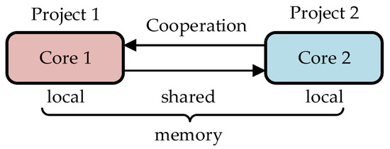
Figure 1.
General architecture of a dual-core PLC.
The runtimes of the cores are copies of a single-core runtime with some minor extensions (see Section 4). Cooperation of the cores through the shared memory is provided by means of global variables.
3.3. Shared Global Variables
Define the following sets of global variables:
GV1—variables updated in Project 1 and used in Project 2.
GV2—variables updated in Project 2 and used in Project 1.
GV = GV1 ∪ GV2—variables shared between Projects 1, 2.
The sets are depicted in Figure 2. The areas outside the GV1 ∪ GV2 circles indicate other global variables declared in the projects but not shared.
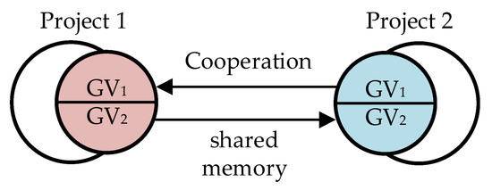
Figure 2.
Sets of global variables in the two projects.
To make cooperation of the projects feasible, the original single-core designs must obey the following rule:
- Declaration of global variables in each of the two projects must contain all shared variables, i.e., the GV set.
Note that application of the rule requires also an extension to GV variable declaration in IDE, so as to indicate whether the variable is updated in the particular project or not. It may be implemented as an additional attribute of the variable, for instance, with WRITE meaning updating in the shared memory the value and READ meaning reading only. Naturally, a GV variable cannot be declared updated in both projects.
3.4. Improvement of Memory Organization
It seems quite probable in industrial practice that the variables from the sets GV1, GV2 will not be declared one after another, but will be scattered among other global variables. Transfer of such scattered variables to/from the shared memory would have to be performed individually, one by one. To make the transfer more time-efficient, the scattered GV1, GV2 variables may be collected into compact memory sectors transferred by fast memory copying. An extension of the single-core compiler for the dual-core application is needed to make such an ordered arrangement. The recommended memory organization after the arrangement is shown in Figure 3.
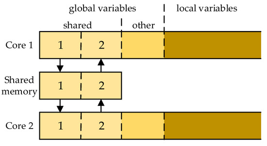
Figure 3.
Memory organization of the dual-core PLC.
After such an arrangement, the relevant sectors of Core 1 memory may be denoted as:
- CM11—sector for GV1 (updated WRITE, another words output);
- CM12—sector for GV2 (received READ—input).
Likewise, we have CM21 (input), CM22 (output) for Core 2, and SH1, SH2 for the shared memory.
3.5. Operation of a Dual-Core PLC
During execution of the binary code, the runtime programs of typical PLCs apply read-execute-write semantics for the scan cycle. This means that all input values are read into internal local copies once a program starts its execution at the beginning of the cycle. During the remainder of the execution, only those local values are used (the mechanism is sometimes called a process image). At the end of the execution, the output values are written into global copies to be used in the next cycle.
In case of Core 1, the content of CM12 memory becomes the input (see Figure 3). However, so far, it is stored in SH2, where it has been copied earlier from CM22, once Core 2 finished its execution. Hence, at the beginning of the Core 1 cycle, SH2 must be copied into CM12. At the end of the execution, the results updated in CM11 are copied into SH1. So, the beginning of execution and the end of the cycles of two cooperating cores may be illustrated as in Figure 4. To implement such behavior, the original single-core runtime must be extended by the copy-from the shared memory at the beginning of the cycle and copy-to at the end. Note that operations executed at the beginning may be called precycle, whereas those executed at the end may be called postcycle.
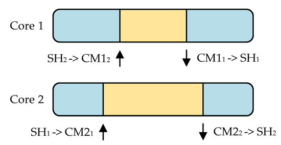
Figure 4.
Scan cycles of the dual-core PLC.
To avoid conflicts between the cores while accessing the shared memory, multi-core processors have built-in hardware semaphores to check whether access is currently possible. Runtime software of each core must involve an algorithm for operating the semaphore, so raising it (releasing) when the data transfer is completed. An example of such an algorithm is shown in Section 5.
To summarize, three extensions of a typical single-core IEC 61131-3 runtime engineering environment are needed for implementation into dual-core PLC running two projects:
- IDE: an additional attribute of a shared global variable to indicate whether it is updated in the actual core or received from the other one.
- Compiler: memory arrangement so as to have updated and received shared variables in compact sectors (optional).
- Runtime: copy-from the shared memory at the beginning of the cycle (precycle) and copy-to at the end (postcycle).
4. Virtual Machine for a Dual-Core Processor
Three types of IEC 61131-3-compliant runtime environments are briefly characterized, namely direct translation of source programs to native code, conversion to C/C++ as the first step, and virtual machine solution with an intermediate language. The virtual machine of the CPDev engineering environment is used for an upgrade to a dual-core. It turns out that two additional instructions of the intermediate language and a semaphore are sufficient for the upgrade.
4.1. Runtime Environments
Compilers of popular control engineering environments such as CODESYS, STEP7, and others mentioned before directly translate IEC 61131-3 programs into native code of a particular processor running the PLC. Fast execution of the code is the basic advantage. However, it is a single-platform solution since changing the CPU requires a new compiler or at least some modifications. Therefore, the approach is appropriate for controllers manufactured in long series, primarily by leading companies.
More flexibility is provided by open-source tools such as Beremiz [30], GEB Automation [31], and OpenPLC [32], where the source programs are converted into C/C++. In case of [30] and [31], another tool is required to translate the C/C++ into native code of a particular CPU. OpenPLC goes further by providing open-hardware solutions for almost 20 platforms, starting from Arduino up to Windows and Linux.
The virtual machine (VM) concept offers another way for expanding the range of CPUs accepted by runtime environment. VM means a simulated processor implemented in software that executes programs written in its own intermediate language. The Java virtual machine [33] and the common language runtime (CLR) of the .NET Framework [34] are general widespread applications of the approach. In the control engineering area, the VM concept was originally introduced in ISaGRAF [35] with an intermediate target independent code. The IEC 61131-3 applications executed by .NET CLR are reported in [36]. An assembler-like intermediate language is used by a VM from [37]. It is written in C and runs on an embedded ARM. Although the VM-based runtimes provide multiplatform applications, execution of the intermediate code is slower since instructions are executed by software instead of directly by hardware components of a CPU.
4.2. CPDev Virtual Machine
CPDev (control program developer) is a VM-based engineering environment used here for a dual-core upgrade. The environment consists of IL/ST/LD/FBD/SFC editors, a compiler that converts source programs into a VMASM (VM assembler) intermediate language, and a VM runtime written in C/C++ [38]. Details on the compiler, VM architecture, and characteristic of VMASM can be found in [39], with examples of controllers for the ship automation and energy sector. The simplified architecture of the VM is shown in Figure 5 for each of the two cores. The instruction processing module fetches successive VMASM instructions from the core memory and executes them, acquiring values from the data or code memories. Results are stored directly in the data memory.
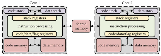
Figure 5.
CPDev virtual machines in a dual-core processor.
The CPDev virtual machine, designed specifically for the execution of control programs, can handle all IEC 61131-3 data types, from BOOL up to WSTRING. The VMASM instructions consist of counterparts of the IEC 61131-3 functions and assembler-like system procedures dealing with the VM architectural components. So, AND, ADD, EXPT, and REAL_TO_INT are examples of the functions. Several system procedures are listed in Table 1 [39].

Table 1.
Exemplary procedures of the VMASM language.
The binary code generator of the CPDev compiler replaces the VMASM mnemonic instructions with digital identifiers and locates variables at particular addresses of data memory. Instructions stored in code memory and various variables in data memory are organized according to limitations of memory access of the executive platform [40]. When executing an instruction, the identifier is decoded by the software of the instruction processing module (Figure 5), which is slower than the hardware decoding and pipelining of the standard CPU. On the other hand, the intermediate code is portable, so no change of the compiler or IDE is needed while switching to a new processor. The source code for the CPDev VM is available at [41]. Formal denotational semantic model of the VM and its implementation are described in [42].
4.3. Upgrade to Dual-Core
Compared to the single-core virtual machine described above, the machine dedicated to dual-core processor must deal with shared memory as a new hardware component. As indicated in Section 3, additional instructions in the runtime program are needed to implement memory copying between the shared memory and the local data memory of a particular core. Naturally, the copying is possible when the other core is not currently doing the same thing. In case of the VMASM language, the extension involves two new copying instructions (system procedures) presented below in a descriptive form:
- CM_TO_SH (LocalAddress, SharedAddress, ByteNumber).
- SH_TO_CM (SharedAddress, LocalAddress, ByteNumber).
Memory addresses and the number of bytes to be copied are the parameters given by the compiler. The semaphore SH_SEM controls the data transfer from/to the shared memory. The raised semaphore means “copying possible”.
One may expect that similar extensions will be needed for another runtime environment upgraded to dual-core solution.
5. Lab Prototype of a Dual-Core PLC
The laboratory prototype involves a dual-core STM32 microcontroller with ARM Cortex-M7 and Cortex-M4 cores. STM32 provides a SEV instruction (send event) for core synchronization and HSEM semaphore to avoid conflicts while accessing the shared memory. A development board is a base for the PLC.
5.1. Multi-Core Processors
As indicated in the introduction, multi-core processors can be divided into microprocessors and microcontrollers. Microprocessors involve a memory management unit necessary to run the operating systems. The A and R profiles in the ARM Cortex family belong to this group. Microcontrollers do not have MMUs, and therefore may run primarily low-level bare-metal (standalone) software. Hybrid solutions have emerged in recent years that consist of both microprocessor and microcontroller cores. This specific combination enables development of more complex devices, for instance, with advanced GUI (graphical user interface) in the microprocessor cores and real-time control and communications handled by microcontroller cores. Examples of multi-core microprocessors, microcontrollers, and hybrids, both homogeneous and heterogeneous, are in Table 2.

Table 2.
Examples of multi-core ARM Cortex processors.
Significant differences between multi-core platforms have led to the development of a universal OpenAMP framework (Section 1) which provides software components for the standardization of inter-core interactions. However, OpenAMP is not needed in bare-metal microcontrollers where the programmer itself is responsible for task synchronization, resource protection, etc., using solutions provided by the chip manufacturer. Applications of bare-metal are typical for low-cost automation devices.
5.2. Lab Prototype with STM32
From the available dual-core microcontrollers, the heterogeneous STM32H755 model from STMicroelectronics [43] has been chosen for the development of the lab prototype. The STM32 consists of the efficient Cortex-M7 (480 MHz) core and the versatile popular Cortex-M4 (240 MHz). The combination of two different cores also enables applications other than PLC+PLC, in particular PLC + GUI/HMI with complex graphic interface. The STM32 development board with external I/O panel and display is shown in Figure 6.
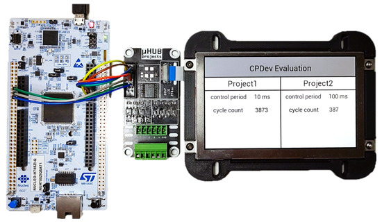
Figure 6.
Nucelo-144 development board with STM32H755 microcontroller and attached external I/O panel and LCD display.
5.3. Time Interrupt and Memory Protection
In case of two real-time applications, there is usually a need to synchronize both. The STM32 chip contains a peripheral called SEV that triggers a mutual hardware interrupt between the cores. This allows an immediate response to be enforced in the system, such as starting a control program or reading new data from the shared memory.
An exemplary synchronization of two projects is shown in Figure 7, also indicating transfers from/to the shared memory with notation from Figure 4. The first core runs a fast logic control every two time units, with the actual execution time taking one time unit. The second core executes a continuous control every nine units, whereas the execution takes five units.
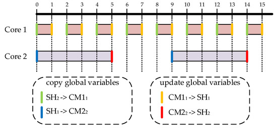
Figure 7.
Execution of two synchronized applications with memory transfers.
In the precycle phase of a particular core, so before executing the control program, the local memory area is updated with global variables evaluated by the other core and transferred to the shared memory. After completing the execution, the shared memory assigned to the first core is updated. Each copy operation from the local memory to the shared memory (by CM_TO_SH virtual machine instruction) is subject to mandatory acquisition of a semaphore at the beginning, followed by release after completing. Writing the current values to the shared memory (SH_TO_CM) proceeds in a similar way.
To protect the shared memory from reading and writing conflicts, the STM32 chip is provided with a classic semaphore called HSEM (actually 32 instances of the semaphore are available; HSEM corresponds to SH_SEM in the previous section). The algorithm shown in Figure 8 permits it to copy data from the shared memory only when the HSEM semaphore is released. The tremcopy in the algorithm denotes the time remaining for copying and the tcycle elapsed execution time of the program. If HSEM = 0 (semaphore down) and the sum tremcopy + tcycle does not exceed the control period, the algorithm remains in the precycle phase, trying to access the shared memory again. When HSEM = 1 (up) the algorithm proceeds to copy the shared sector involving the relevant global variables. If the sum tremcopy + tcycle exceeds the control period, the system will end the precycle phase and start executing the control program, signaling the failure in the flag register. This safeguard is required for correct cyclical operation in accordance with the IEC 61131-3 standard.
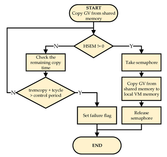
Figure 8.
Algorithm to copy global variables from the shared memory to local memory during the virtual machine precycle.
6. Running Two Projects and Tests
The original single-core CPDev engineering environment has been extended to enable the development and execution of two IEC 61131-3 projects by a dual-core microcontroller according to the guidelines from previous sections. Specifically, the extensions correspond to the ones indicated at the end of Section 3, so shared attribute of relevant global variables, ordered arrangement of the shared variables, and transfer to/from the shared memory in the runtime. Likewise, the IDE online monitoring tool used to set and display variables has been extended accordingly. Common time interrupt provides synchronization of the cores. Experimental results indicate that organization of the shared memory into compact sectors can substantially reduce communication overhead.
6.1. Details of the Projects
Cooperation of two projects is demonstrated here using a simple FBD diagram and ST code to count input pulses, monitor impulse time, and transfer signals between cores, as shown in Figure 9 and Figure 10. The FBD diagram is executed every 10 ms, and the ST code every 100 ms. All variables in the projects are global.
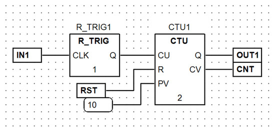
Figure 9.
FBD diagram for Project 1.
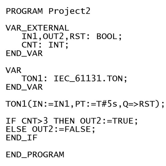
Figure 10.
ST program for Project 2.
In the first project, the pulse from IN1 connected to one of the I/O panel digital inputs is fed to the rising edge detector R_TRIG1 and then to up-counter CTU1 (R_TRIG1, CTU1 are instances of standard blocks). The count is given at CNT, whereas OUT1 indicates whether CNT has reached the limit 10. The counter CTU1 can be reset by the signal RST. The second project involves the timer TON1 that monitors the signal IN1 received from Project 1. If IN1 is set for at least 5 s, the timer output Q goes high, which through RST resets the counter CTU1 in Project 1. Furthermore, Project 2 at OUT2 monitors whether CNT exceeds 3.
As seen from the description, the signals IN1, CNT, and RST are shared between the projects. Additional attributes required to implement sharing (Section 3.3) are given in Table 3, where WRITE indicates a global variable updated in the project and READ received from the other one. The variable OUT1 in Project 1 and OUT2 in Project 2 are global in the respective projects, but not shared.

Table 3.
Additional attributes of the shared global variables.
The operation of the cores is demonstrated in Figure 11 on the display panels of the IDE monitoring tool. The first row indicates an exemplary state after processing five pulses at IN1. Since CNT exceeds three, OUT2 in Core 2 is set (red). The second row represents the state after 10 pulses, so the output OUT1 becomes TRUE (red). The last row indicates values while keeping IN1 set for more than 5 s. So RST is set to TRUE which resets the counter back to 0.
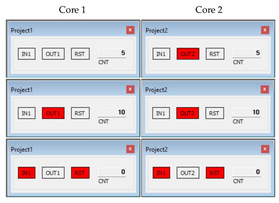
Figure 11.
Testing the dual-core PLC.
6.2. Experimental Results
The STM32H755 chip involves hardware counters, including timers that can be connected to interrupt controllers (NVICs) of the cores. Synchronization of the control projects (tasks) is implemented by connecting a common master timer to the interrupt controllers of both cores. The use of SysTick that counts time since processor power-up can be another way of synchronization.
The results on communication overhead and time consumption for three tests are given in Table 4. To ensure reasonable accuracy of time measurements by a logic analyzer and to decrease delays introduced by internal buses of the processor, a common fairly low operating frequency 4 MHz has been chosen. Note that it is many times lower than the maximum of 480 MHz for Core 1 (Cortex-M7) and 240MHz for Core 2 (Cortex-M4). Therefore, the precycle, cycle (calculations), and postcycle are given in milliseconds, and not in microseconds as one could expect.

Table 4.
Precycle, cycle, and postcycle in [ms] for 4MHz.
The tests denoted by 100/200 DWORD are loops involving arrays whose 4-byte items are (1) read out from the shared memory, (2) increased by three, and (3) written back to the shared memory. The same loop is executed synchronously by the second core, so the cores continuously cooperate. To test communication overhead, the array is firstly treated as a compact memory sector and secondly as a group of items distributed “at random”. Therefore the “compact” case corresponds to Figure 3 with the preferred memory organization. For the 100 DWORD test, the execution involves one copying of 400 bytes to local memory and two virtual machine Set/GetData instructions for 200 bytes each (VM limits the size to 256). In case of “random” where each item is treated independently, there are 100 or 200 memory copyings for each of the DWORD.
The difference between “compact” and “random” communications is seen in the precycle and postcycle, where the transfer from/to the shared memory actually takes place. For 100 DWORD, the random/compact ratio is 8.7 for the precycle and 9.5 for postcycle. The ratios for 200 DWORD are 9.1 and 9.6, respectively. The ratios clearly indicate that careful organization of memory as in Figure 3 can substantially reduce communication overhead. Recall, however, that memory organization is the task of the compiler which should be upgraded for dual-core applications.
The time consumptions of the processor to execute the calculations are given in the cycle column of Table 4. Codes in examples from Section 6.1 are executed only once, which explains the much lower cycle values than for the loops 100/200 DWORD. As may be expected, there is almost no difference between “compact” and “random” as far as calculations are concerned. We repeat that the time values in Table 4 have been obtained for quite low operating frequency of the cores. For typical much higher frequencies, the times would be correspondingly lower.
7. Conclusions
A dual-core PLC capable of running two IEC 61131-3 projects has been developed. As a precondition, the shared variables must be declared global in both projects. To upgrade a single-core engineering environment for two cores, three steps are needed:
- New attribute of each shared variable indicating whether it is updated or received in a project.
- Compact sectors for the shared variables in the controller memories (optional).
- Data transfers from/to the shared memory at the beginning and end of the control cycle.
The steps can be implemented in IDE, compiler, and runtime. As an example, a VM-based environment has been upgraded to two cores to demonstrate the solution. The prototype PLC involves the heterogeneous dual-core STM32 microcontroller with time synchronization and protection against data transfer conflicts. The execution of two cooperating projects confirms the feasibility of the approach.
As indicated in the introduction, a dual-core PLC may provide similar capabilities as two tasks of a real-time OS running a controller in a DCS system. In case of more tasks, a multi-core processor could be a low-cost alternative.
Future work will concentrate on the PLC + HMI solution with graphical objects interfaced to PLC global variables through shared memory, and on the extension of the current single-core denotational semantic model to dual-core.
Author Contributions
Conceptualization, B.T.; Software, M.H.; Writing—original draft, B.T. and M.H.; Writing—review & editing, B.T.; Visualization, M.H.; Funding acquisition, B.T. All authors have read and agreed to the published version of the manuscript.
Funding
This project was financed by the Ministry of Education and Science of the Republic of Poland within the “Regional Initiative of Excellence” program for the years 2019–2023. Project number 027/RID/2018/19, amount granted 11,999,900 PLN.
Data Availability Statement
The data presented in this study are openly available in https://github.com/CPDev-ControlProgramDeveloper, accessed on 24 October 2023.
Acknowledgments
We sincerely thank Leszek Trybus for his invaluable support, encouragement, and motivation in our work.
Conflicts of Interest
The authors declare no conflict of interest.
References
- Automation Technology for PLCnext Technology. Phoenix Contact. Available online: https://www.phoenixcontact.com/en-gb/products/plcs-controllers-and-i-os/automation-technology-for-plcnext-technology (accessed on 11 October 2023).
- CX8200|Embedded PC Series (Compact Controller). Beckhoff Automation. Available online: https://www.beckhoff.com/en-en/products/ipc/embedded-pcs/cx8200-arm-cortex-a53/ (accessed on 11 October 2023).
- John, K.H.; Tiegelkamp, M. IEC 61131-3: Programming Industrial Automation Systems; Springer: Berlin/Heidelberg, Germany, 2010. [Google Scholar] [CrossRef]
- ARM Microcontrollers Market Size, Share, Opportunities & Forecast. Verified Market Research. Available online: https://www.verifiedmarketresearch.com/product/arm-microcontrollers-market/ (accessed on 11 October 2023).
- The OpenAMP Project. Available online: https://www.openampproject.org/ (accessed on 11 October 2023).
- Zynq 7000 SOC. AMD (XILINX). Available online: https://www.xilinx.com/products/silicon-devices/soc/zynq-7000.html (accessed on 11 October 2023).
- Cisek, J.; Mikluszka, W.; Świder, Z.; Trybus, L. A Low-Cost DCS with Multifunction Instruments and CAN Bus 1. IFAC Proc. Vol. 2001, 34, 64–69. [Google Scholar] [CrossRef]
- Martos, P.I. Architectural Patterns for Asymmetric Multiprocessing Devices on Embedded Systems. In Proceedings of the SugarLoafPLoP ’16: Proceedings of the 11th Latin-American Conference on Pattern Languages of Programming, Buenos Aires, Argentina, 16 November 2016; pp. 1–13. [Google Scholar]
- Becker, M.; Sandström, K.; Behnam, M.; Nolte, T. A Many-Core Based Execution Framework for IEC 61131-3. In Proceedings of the IECON 2015—41st Annual Conference of the IEEE Industrial Electronics Society, Yokohama, Japan, 9–12 November 2015. [Google Scholar] [CrossRef]
- Mubeen, S.; Becker, M.; Zhao, X.; Gan, L.; Behnam, M.; Nolte, T. Towards Automated Deployment of IEC 61131-3 Applications on Multi-Core Systems. In Proceedings of the 2016 IEEE World Conference on Factory Communication Systems (WFCS), Aveiro, Portugal, 3–6 May 2016. [Google Scholar] [CrossRef]
- Specht, F.; Flatt, H.; Eickmeyer, J.; Niggemann, O. Exploiting Multicore Processors in PLCs Using Libraries for IEC 61131-3. In Proceedings of the 2015 IEEE 20th Conference on Emerging Technologies & Factory Automation (ETFA), Luxembourg, 8–11 September 2015. [Google Scholar] [CrossRef]
- Ning, B.; Li, D.; Ling, Y.; Zhihua, B.; He, L.; Zhang, G.; Li, M. Asymmetric Software Architecture Design of High Performance Control Chip Applied in Industrial Control Field. In Proceedings of the 2021 4th International Conference on Advanced Electronic Materials, Computers and Software Engineering (AEMCSE), Changsha, China, 26–28 March 2021. [Google Scholar] [CrossRef]
- Salčić, Z.; Nadeem, M.; Park, H.; Teich, J. A Heterogeneous Multi-Core SoC for Mixed Criticality Industrial Automation Systems. In Proceedings of the 2016 IEEE 21st International Conference on Emerging Technologies and Factory Automation (ETFA), Berlin, Germany, 6–9 September 2016. [Google Scholar] [CrossRef]
- Mazur, P.; Czerwinski, R.; Chmiel, M. PLC Implementation in the Form of a System-on-a-Chip. Bull. Pol. Acad. Sci. Tech. Sci. 2020, 68, 1263–1273. [Google Scholar] [CrossRef]
- Zoitl, A.; Lewis, R.W. Modelling Control Systems Using IEC 61499; The Institution of Engineering and Technology: Stevenage, UK, 2014. [Google Scholar] [CrossRef]
- Ochoa-Ruiz, G. Enabling Adaptable IEC 61499-Based Cyber-Physical Systems Using SoC FPGAs and Partial Reconfiguration. ACM Comput. Surv. 2020. [Google Scholar] [CrossRef]
- Sun, Y.; Li, E.; Yang, G.; Liang, Z.; Guo, R. Design of a Dual-Core Processor Based Controller with RTOS-GPOS Dual Operating System. In Proceedings of the 2019 IEEE International Conference on Mechatronics and Automation (ICMA), Tianjin, China, 4–7 August 2019. [Google Scholar] [CrossRef]
- Cong, V.D. Industrial Robot Arm Controller Based on Programmable System-on-Chip Device. FME Trans. 2021, 49, 1025–1034. [Google Scholar] [CrossRef]
- Dočekal, T.; Slanina, Z. Control System Based on FreeRTOS for Data Acquisition and Distribution on Swarm Robotics Platform. In Proceedings of the 2017 18th International Carpathian Control Conference (ICCC), Sinaia, Romania, 28–31 May 2017. [Google Scholar] [CrossRef]
- Alonso, S.; Lázaro, J.; Jiménez, J.; Muguira, L.; Bidarte, U. Evaluating the OpenAMP Framework in Real-Time Embedded SoC Platforms. In Proceedings of the 2021 XXXVI Conference on Design of Circuits and Integrated Systems (DCIS), Vila do Conde, Portugal, 24–26 November 2021; pp. 1–6. [Google Scholar] [CrossRef]
- Alonso, S.; Lázaro, J.; Jiménez, J.; Bidarte, U.; Muguira, L. Evaluating Latency in Multiprocessing Embedded Systems for the Smart Grid. Energies 2021, 14, 3322. [Google Scholar] [CrossRef]
- Queiroz, R.; Cruz, T.; Simões, P. Testing the Limits of General-Purpose Hypervisors for Real-Time Control Systems. Microprocess. Microsyst. 2023, 99, 104848. [Google Scholar] [CrossRef]
- Mariton, M.; Bertrand, P. Reliable Flight Control Systems: Components Placement and Feedback Synthesis. IFAC Proc. Vol. 1987, 20, 151–155. [Google Scholar] [CrossRef]
- Losada, M.; Adin, I.; Perez, A.; Ramírez, R.C.; Mendizabal, J. Connected Heterogenous Multi-Processing Architecture for Digitalization of Freight Railway Transport Applications. Electronics 2022, 11, 943. [Google Scholar] [CrossRef]
- Ulmer, D.; Wittel, S.; Huenlich, K.; Rosenstiel, W. A Hardware-in-the-Loop Testing Platform Based on a Common Off-The-Shelf Non-Real-Time Simulation PC. In Proceedings of the Sixth International Conference on Systems, St. Maarten, The Netherlands, 23–28 January 2011. [Google Scholar]
- CODESYS. Available online: https://www.codesys.com/ (accessed on 11 October 2023).
- SIMATIC STEP 7 (TIA Portal). SIEMENS. Available online: https://www.siemens.com/global/en/products/automation/industry-software/automation-software/tia-portal/software/step7-tia-portal.html (accessed on 11 October 2023).
- Automation Builder. Available online: https://new.abb.com/plc/automationbuilder (accessed on 11 October 2023).
- LogicLab. Available online: https://www.axelsoftware.it/en/logiclab/ (accessed on 11 October 2023).
- Beremiz. Available online: https://beremiz.org/ (accessed on 11 October 2023).
- GEB Automation. Available online: https://www.gebautomation.com/ (accessed on 11 October 2023).
- OpenPLC. Available online: https://autonomylogic.com/ (accessed on 11 October 2023).
- Lindholm, T.; Yellin, F.; Bracha, G.; Buckley, A. The Java Virtual Machine Specification, Java SE 8 Edition; Addison-Wesley Professional: Redwood City, CA, USA, 2014. [Google Scholar]
- Richter, J. CLR via C#, 4th ed.; Microsoft Press: Washington, DC, USA, 2012. [Google Scholar]
- ISaGRAF Technology. Available online: https://www.rockwellautomation.com/en-us/support/documentation/technical-data/isagraf_20190326-0743.html (accessed on 11 October 2023).
- Cavalieri, S.; Puglisi, G.; Scroppo, M.S.; Galvagno, L. Moving IEC 61131-3 Applications to a Computing Framework Based on CLR Virtual Machine. In Proceedings of the 2016 IEEE 21st International Conference on Emerging Technologies and Factory Automation (ETFA), Berlin, Germany, 6–9 September 2016. [Google Scholar] [CrossRef]
- Zhang, M.; Lu, Y.; Xia, T. The Design and Implementation of Virtual Machine System in Embedded SoftPLC System. In Proceedings of the 2013 International Conference on Computer Sciences and Applications, San Francisco, CA, USA, 23–25 October 2013. [Google Scholar] [CrossRef]
- Trybus, B. Development and Implementation of IEC 61131-3 Virtual Machine. Theor. Appl. Inform. 2011, 23, 21–35. [Google Scholar] [CrossRef][Green Version]
- Sadolewski, J.; Trybus, B. Compiler and virtual machine of a multiplatform control environment. Bull. Pol. Acad. Sci. Tech. Sci. 2022, 70, 140554. [Google Scholar] [CrossRef]
- Hubacz, M.; Trybus, B. Data Alignment on Embedded CPUs for Programmable Control Devices. Electronics 2022, 11, 2174. [Google Scholar] [CrossRef]
- CPDev-ControlProgramDeveloper. GitHub. Available online: https://github.com/CPDev-ControlProgramDeveloper (accessed on 11 October 2023).
- Sadolewski, J.; Trybus, B. Denotational Model and Implementation of Scalable Virtual Machine in CPDEV. In Proceedings of the Computer Science and Information Systems (FedCSIS), Federated Conference On 2022, Sofia, Bulgaria, 4–7 September 2022. [Google Scholar] [CrossRef]
- STMicroelectronics. Available online: https://www.st.com/content/st_com/en.html (accessed on 11 October 2023).
Disclaimer/Publisher’s Note: The statements, opinions and data contained in all publications are solely those of the individual author(s) and contributor(s) and not of MDPI and/or the editor(s). MDPI and/or the editor(s) disclaim responsibility for any injury to people or property resulting from any ideas, methods, instructions or products referred to in the content. |
© 2023 by the authors. Licensee MDPI, Basel, Switzerland. This article is an open access article distributed under the terms and conditions of the Creative Commons Attribution (CC BY) license (https://creativecommons.org/licenses/by/4.0/).