Abstract
Legalized routing is an essential part of PCB automatic routing. It solves the problem of wiring conflicts and obtains routing results that comply with the constraints of design rules. Traditional legalized routing problems mostly use trial backtracking methods, but with increasing design complexity and design rules, avoiding wiring conflicts between networks has become increasingly challenging. This paper proposes a legalized routing algorithm based on linear programming to obtain the optimal wiring trajectory under specified topological constraints. First, the corresponding routing model was established based on numerous routing rules, and a routing grid diagram was found using obstacles as grid points. Secondly, a global routing algorithm was used to obtain the estimated wiring path, and integer linear programming was used to realize the mathematical modeling of the legalized routing problem. Finally, a multi-line simultaneous routing strategy was used to design and implement a detailed routing algorithm, optimizing the routing results. We use C++ to complete the coding work and thoroughly test the PCB use cases of different sizes. The experimental results show that our algorithm still maintains a 100% routing success rate, good time performance, and excellent routing quality with large-scale use cases compared with the trial backtracking method.
1. Introduction
Printed circuit boards are an important part of the electronics industry and are used in almost every type of electronic equipment [1,2]. Since the invention of PCB boards, there has been development towards large-scale and high integration [3], making manual wiring more and more complex and demanding. To meet the needs of production and life, research on PCB automatic routing algorithms has gradually become a hot topic in recent years. Complex functions and design goals have dramatically increased the number and density of pins, and the difficulty of automatic routing is growing daily [4]. Currently, no algorithm can perfectly solve all automatic routing problems. Especially when the internal pin arrangement of a device is irregular, the routing scenarios to be considered are more complex, and there are always problems, such as a low routing rate and violation of design rule constraints (DRC). It can only be automated to a certain extent, and manual wiring is required to correct it to obtain the expected routing results. Legalized or detailed routing [5,6,7] is a critical challenge in automatic routing design. It solves the problem of routing paths violating design rules, reflects the quality of routing results, and is an important criterion for determining the quality of automatic routing algorithms.
1.1. Previous Work
According to the routing area, PCB routing problems can be divided into escape routing and bus routing [8]. Escape routing realizes wiring from pins to device boundaries [9], which is point-to-line wiring. Bus routing completes the interconnection of the corresponding pins between devices, which is point-to-point wiring. Legalized escape routing saves routing space in the bus routing stage and dramatically improves the overall PCB routing success rate. However, these two stages do not always work well together, and a successful escape route can lead to an area route without a solution. In traditional technology, escape routing and bus routing are routed simultaneously as a whole, but this solution cannot accurately optimize routing resources. Escape and bus routing have been considered separate issues in recent years. Escape routing can be divided into ordered escape routing [10,11,12] and unordered escape routing [8,13,14]. Unordered escape routing usually leads to complex length routing, so the issue of ordered escape routing (OER) has received more attention.
Luo and Wang proposed that the OER problem could be modeled as a planar Boolean satisfiability problem [15] and that the problem could be solved using an existing Boolean satisfiability solver. However, this does not solve the capacity limitation problem. In 2009, Yan et al. proposed a new network flow model modeling approach [13], which solved the problem of diagonal capacity modeling on the original basis. However, this model may lose many optimal solutions. In 2016, Jiao et al. first proposed the minimum-cost, multi-commodity flow (MMCF) method to solve the OER problem [16], mainly by adding many virtual transit nodes to the original network flow model to meet the constraints of ordered escape routing. Later, Zhao et al. suggested using ILP to solve the OER problem [17]. However, this method, which divides large-scale printed circuit boards into small scales to escape independently, does not solve the significant problem of surrounding obstructions caused by the dispersion of a similar number of pins, which can easily lead to routing failures or timing conflicts.
Legalized routing is the last stage of the automatic routing process, so the routing results must meet the design rule checks, such as line width, spacing, wiring angle, etc., and the specific wiring that meets the DRC is output as the final routing result [18,19]. Most previous research considers the search wiring path and legalized routing simultaneously and uses the trial backtracking method to achieve detailed routing, which cannot solve complex routing scenarios, such as irregular pin arrangements.
1.2. Our Contributions
This paper considers a legalized routing algorithm based on the ordered escape routing module, considering routing path search and legalized routing as two stages occurring before and after. A suitable routing path is given through the existing path search algorithm, and the legalized routing is realized on this basis. Our main contributions are summarized as follows:
- To simplify the complexity of the detailed routing problem, a solution to realize the wiring using a prescribed topology is proposed, and a specific wiring model is established based on complex design rules;
- Integer linear programming is used to realize the mathematical modeling of detailed wiring problems, and a legalized wiring algorithm based on linear programming is proposed to effectively realize the legalized wiring function of grid pin array (GPA) and staggered pin array (SPA) devices;
- The heuristic strategy of multi-line routing is used to design and implement a detailed routing algorithm, further optimizing the routing quality and the time complexity.
The remainder of this article is organized as follows: Section 2 presents a problem statement and proposes a routing topology. Section 3 describes how we can use integer linear programming [20,21,22,23] to complete the mathematical modeling of the legitimized routing problem. Section 4 introduces our proposed detailed routing algorithm. Section 5 presents the experimental results, and Section 6 concludes our work.
2. Model Building
2.1. Problem Statement
The legalized routing problem can be formulated as follows:
Within a specified routing area, there is a set of estimated routing points from the origin to the destination, and the routing trace determined by this set of points violates routing rules. As shown in Figure 1, there are circular and square obstacles in the routing area, and the routing trajectory consists of a point set . Based on the obstacle information, we must improve the estimated path and find a routing result that satisfies all the design rules.
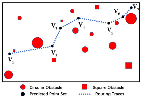
Figure 1.
Schematic diagram of estimated routing in a complex scene with multiple obstacles.
For PCB automatic routing, the main constraints considered in this paper are as follows:
- Spacing constraints: The distance between the routing trace and the obstacle is greater than or equal to the minimum spacing value;
- Routing direction and angle constraint: The angle between the routing direction and the x-axis must be a multiple of 45°, and the routing direction can only be changed by 135°;
- Minimum line length constraint: The shortest line length determined by two points must be greater than or equal to the line width.
Figure 2 is a schematic diagram of the ordered escape routing of a grid pin array device. The routing from all the designated pins to the device boundary must be completed. The escape routing grid diagram is constructed with the pins as grid points, and each pin’s escape path and boundary position are determined through the routing path search stage. The escape paths of different pins in the figure are recorded through the edges in the grid diagram, indicating the passing position and adjustable range of the estimated point set. Line segments and arrows of different colors distinguish them. In the automatic routing stage, the legalized routing must complete the routing from the pin to the boundary according to the routing sequence. At the same time, the legalized routing function can also be used to post-process the routing results to repair the routing that does not meet the DRC.
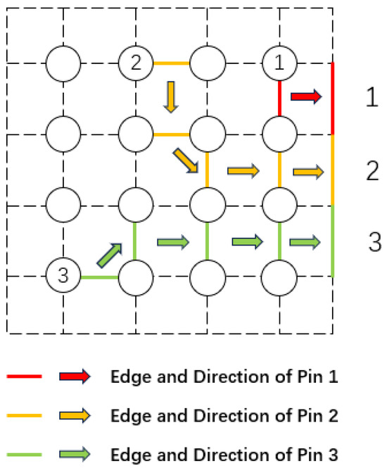
Figure 2.
Schematic diagram of orderly escape routing of GPA package devices.
2.2. Routing Topology
The path determined by the escape routing grid diagram divides all local routing scenarios into three situations: left-in and top-out, left-in and right-out, and left-in and down-out, as shown in Figure 3. Among them, Figure 3a–c take the left side as the incoming edge, the right side as the outgoing edge, and the upper side of Figure 3d,e is the outgoing edge. The situation of left-in and bottom-out is the same as that of left-in and top-out. Just flip the Figure 3d,e up and down. The scene with other edges as the incoming edge is the same as the scene with the left as the incoming edge, and only the corresponding coordinate conversion is required.
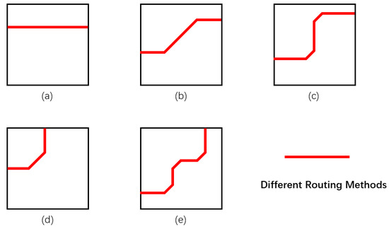
Figure 3.
Routing topology in different scenarios. (a) One-segment of left-in-right-out. (b) Two-segment of left-in-right-out. (c) Three-segment of left-in-right-out. (d) Three-segment of left-in-top-out. (e) Seven-segment of left-in-top-out.
For different routing scenarios, we adopt the corresponding topology as the routing line type to meet the DRC. For left-side entry and right-side exit, three different topological structures are used, consisting of one, three, and five line segments. Two other topological structures are used for the left-side entry and top-side exit, composed of three and seven line segments, respectively. A variety of topologies are used to adapt to staggered pin array devices, irregular pin array devices, and other complex routing scenarios.
The routing types shown in Figure 3 all satisfy the routing direction and angle constraints. Under the constraint of fixed topology, as long as the minimum line length constraints and distance regulations to obstacles are met, legalized routing results that comply with DRC can be obtained. Ordered escape routing conducts the routing of each pin in sequence according to the order of the boundary. The routing path from the pin to the boundary comprises routing edge sets, and legalized escape routing is implemented from the local to the whole. The legalized routing of a certain line network needs to consider the impact on other nearby line networks. At the same time, this article focuses on the routing success rate and quality, which are also the performance indicators. The low routing rate cannot meet the automation requirements, and the unreliable routing results must be dismantled and rewired, which is more time-consuming and laborious.
3. Linear Programming Modeling
This section describes modeling the legalized routing problem through linear programming. Figure 4 is a flowchart of the legalized routing algorithm. Firstly, the routing grid diagram is constructed according to the obstacle information in the figure. Then, the estimated routing path is determined through the estimated point set, and the legal routing model is established by the routing topology proposed in Section 2.2. Then, linear programming modeling is performed based on the routing rule constraints considered in this article, and, finally, the routing results are solved and output through the solver.
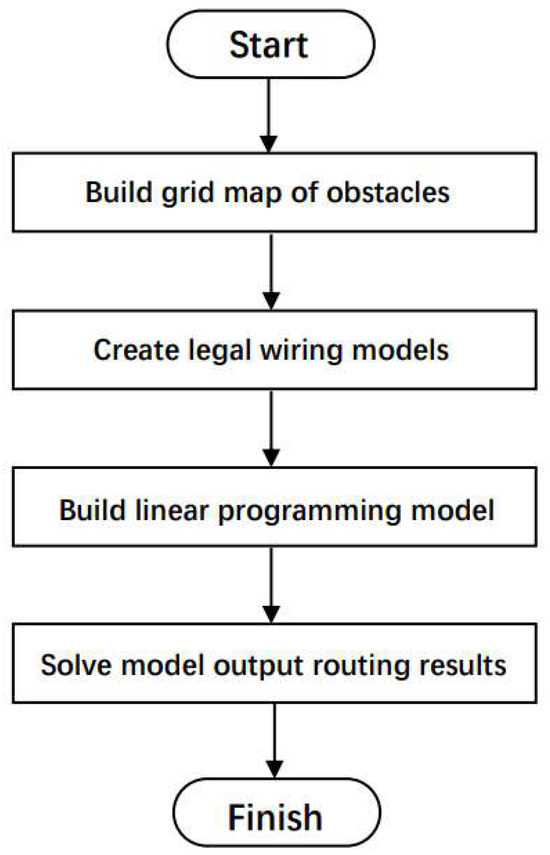
Figure 4.
Legalized routing flowchart.
3.1. Composition and Routing Model Establishment
Figure 5 is our simulated routing scene. There are a large number of circular or square obstacles scattered in the routing area. The estimated point set of a certain line network is composed of . A grid diagram is constructed using the center points of the circular and square obstacles as grid points. The horizontal and vertical grid lines intersect with each other to divide the plane into multiple rectangular areas. The obstacle grid graph consists of each rectangle with its vertices and edges. The estimated point set is fitted to the edge of the grid diagram and extended appropriately around to form a merged edge as a routing edge, as shown in the green line segment in Figure 5. The routing edge corresponds to the estimated points one-by-one, and the adjustment range of each point is determined.
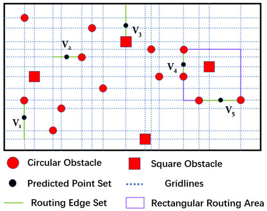
Figure 5.
Obstacle grid diagram.
The estimated routing path is composed of all the routing edges, and the point-to-point routing problem is converted into a line-to-line routing problem. The minimum rectangle determined by the two edges is used as the local wiring area, as shown in the purple rectangular box in Figure 5. According to the routing edge’s location, the corresponding scenario’s routing topology is adopted to establish a legal routing model.
3.2. Integer Linear Programming
The essential requirement of legalized routing is that the routing results meet all the design rule constraints. The success rate of routing is also an important indicator that must be considered. An infinite number of feasible solutions may satisfy DRC in each local routing area identified above. If it is assumed that multiple wire nets need to be wired in the routing area simultaneously, in that case, it is necessary to occupy as little routing space as possible during routing to improve the routing success rate of the other wire nets.
Clockwise wiring rules are used to constrain it to improve the routing rate. For each local routing rectangle, the area of the polygon formed by going clockwise around the rectangular boundary from the routing startpoint to the endpoint should be as small as possible. The legalized routing problem is treated as an optimization problem, and integer linear programming is used for the mathematical modeling. The linear programming process is introduced through the routing scenario with the left side as the entry edge, and the linear programming expression of a specific line network is derived from this.
Figure 6 is a schematic diagram of the linear programming of the three-segment topology in the left-in-right-out scenario. As shown in Figure 6a, there are seven obstacles of different sizes and shapes in the routing area, and they are marked with 1–7 as , , …, . The routing track is composed of four vertices and three line segments. The coordinates of points A, B, C, and D are set to (, ), (, ), (, ), and (, ), respectively. In Figure 6b, the center point of the obstacle is taken as the obstacle coordinates marked as (, ), (, ), …, (, ). The downward ray is taken, starting from point B as the axis, and the upward ray , starting from point C as the axis. The routing area is divided into four blocks, which are recorded as 00, 01, 10, and 11, respectively.
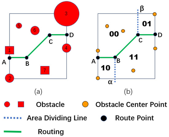
Figure 6.
Left-in and right-out linear programming diagram. (a) Left-in-right-out schematic diagram. (b) Linear programming diagram.
First, the spacing constraint requirements are considered to record the minimum spacing between each obstacle and the trace as , . includes the length from the obstacle coordinates to the obstacle boundary, the distance from the obstacle boundary to the trace, and the line width W. The topology structure naturally satisfies the routing direction and angle constraints. Considering the minimum line length constraint, is recorded as the minimum line length. At the same time, according to the clockwise routing requirements, the routing area occupied above the polyline should be as small as possible. To sum up, this situation can be expressed by a mathematical model as:
Among them, the decision variables are the coordinates , , , , , , , of points A, B, C, and D. The obstacle coordinates and are constants, and M is a sufficiently large integer constant. The objective function is given by Formula (1), which is the sum of the distance from obstacle to point A, the distance from line segment , and the distance from obstacle to point D. When Z takes the minimum value, the clockwise routing constraint is satisfied. Formula (2) represents the dependencies between the routing trajectory points of the topology, Formula (3) determines the value range of the boundary points, and Formula (4) represents the minimum line length constraint.
Obstacles are divided into four types through the axes , , and the routing trajectories. Obstacles located in different areas correspond to various constraints. In order to unify the spacing constraints of obstacles in different areas, two (0,1) variables , are set for each obstacle. Their different values are combined to correspond to different regions of the mark, multiplied by M, and substituted into the spacing constraint to unify multiple mutually exclusive constraints. Among them, Formulas (5)–(7) represent the obstacle constraint conditions located in the 00 area, Formulas (8) and (9) represent the 01 region constraint conditions, Formulas (10) and (11) represent the 10 region constraint conditions, and Formulas (12)–(14) represents the 11 region constraint conditions.
Figure 7 is a schematic diagram of linear programming in the left-in-top-out scenario we simulated. The obstacle is , and the minimum distance between the obstacle and the trace is . The coordinates of the obstacle center point are (, ), . The coordinates of points A, B, C, and D are set to (, ), (, ), (, ), (, ), respectively, and the minimum line length is L. The ray downward from point B and the ray to the right from point C divide the routing area into four blocks: 00, 01, 10, and 11. Considering the DRC constraints and the clockwise routing constraints, the left-in-top-out mathematical model can be expressed as:
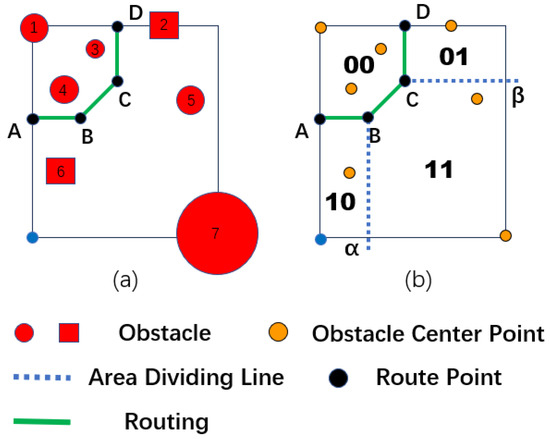
Figure 7.
Left-in and top-out linear programming diagram. (a) Left-in-top-out schematic diagram. (b) Linear programming diagram.
The decision variables are the coordinates of the routing trajectory points, the obstacle coordinates are constants, and M is a sufficiently large integer constant. The objective function is given by Formula (16), and the routing trajectory point that minimizes the Z value is solved. Formula (17) represents the line type constraint, Formula (18) limits the value range of the boundary point, and Formula (19) represents the minimum line length constraint. At the same time, two (0, 1) variables, , and are set for each obstacle, and their different value combinations correspond to the four routing areas divided by the axes and to achieve the unification of spacing constraints in different regions. The linear programming process in other scenarios can be considered analogously to the above two scenarios.
The complete routing result of a net consists of the routing results of each local area. Assume that the estimated routing point set V = , , …, , n > 2, corresponds to local routing areas. In comprehensive local area linear programming, the overall linear programming expression is as follows:
Among them, () corresponds to the objective function of the i-th routing area, and () represents the constraints of the i-th routing area. By solving Formula (31), the optimal routing result that satisfies the DRC and clockwise routing rules can be obtained. Using linear programming and solving the nets in sequence, the ordered escape routing results of the device can be obtained.
4. Detailed Routing Algorithm
Legal escape routes with a high routing success rate can be guaranteed through integer linear programming. However, as the device’s size increases, the number of pins and variables increases sharply, resulting in an over long solution time when dealing with large-scale routing problems. Therefore, this paper proposes a heuristic routing scheme to optimize the algorithm and to improve the time performance. At the same time, to improve the routing quality, multiple nets in the local routing area are routed simultaneously, making the routing results more beautiful and reliable.
Figure 8 is a detailed routing algorithm framework flowchart. Linear programming solves the routing of a certain net each time. The heuristic algorithm first divides the escape routing grid graph into different local routing areas based on the estimated routing paths. It constructs a directed acyclic graph with the local routing areas as nodes. Then, the local area routing sequence is obtained through topological sorting, the regional legalized routing is implemented in order, and the routing results are output.
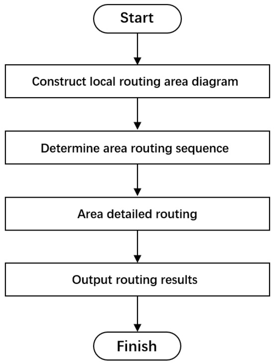
Figure 8.
Detailed routing algorithm flowchart.
Figure 9 is a schematic diagram of the local routing area when using the detailed routing algorithm for wiring. A total of 5 pins A, B, C, D, and E need to escape. All the routing edges are numbered and highlighted in red, and arrows of different colors indicate the estimated routing path for each pin. The local routing area is composed of connected edges before and after. As shown in the routing area composed of edges 3, 4, and 6 in Figure 9, pin A is routed from edge 3 to edge 4, and pin B is routed from edge 3 to edge 6. Local routing is carried out, and the edges are divided in the routing area into incoming and outgoing edges and route different nets from their incoming edge to the outgoing edge. The point passing through the incoming edge is the in point, and the point passing through the outgoing edge is the out point. The out point of this area serves as the in point of the following routing area. The legalized routing problem is converted into a point-to-line routing problem. The edge where the pin is located treats the pin coordinates as a determined point separately.
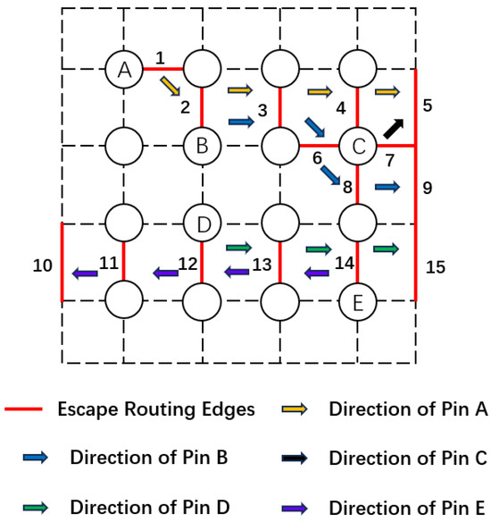
Figure 9.
Schematic diagram of multi-line synchronous routing area.
When conducting regional detailed routing, the influence of multiple nets in the region should also be considered to make the routing traces more uniform. At the same time, other routing areas are referred to with a front-to-back connection relationship to ensure that the points given in the routing results in this area are within a reasonable range and do not affect the wiring in subsequent regions. Without affecting the routing success rate, different preference parameters can be added for parameter adjustment to minimize the local routing length, avoid winding caused by clockwise routing constraints, and to make it more beautiful. According to the regional routing sequence, legalized escape routing is implemented from local to global.
5. Experimental Results
This section demonstrates the high efficiency of the proposed linear-programming-based routing model in solving the escape routing legalization problem. The algorithm in this article is programmed and implemented on the VS2022 platform using C++ language, and the linear model is optimized and solved using the Gurobi9.1 [24] solver. The algorithm runs on a PC with an Intel Core i7 processor (2.30 GHz) and 16 GB of memory.
We collected eight industrial PCB boards of different sizes for the experiments. Table 1 shows the parameter statistics of the different test cases, including the number of pins, the number of obstacles, the number of devices, the number of routing layers, and the number of nets that need to be routed. The obstacles are composed of pins and holes. First, we use the existing ordered escape routing algorithm to complete hierarchical sequencing and give the estimated routing path of each pin. Then, we use the trial backtracking algorithm, the linear programming algorithm, and the detailed routing algorithm to legalize the routing. Table 2 shows the statistics of the experimental results for different algorithms on test cases, including the total routing length, running time, routing rate, and number of DRC violations. Figure 10 and Figure 11 are partial diagrams of the experimental results using the detailed routing algorithm under the Case5 use case.

Table 1.
PCB use case parameter statistics.

Table 2.
Legalized routing result statistics.
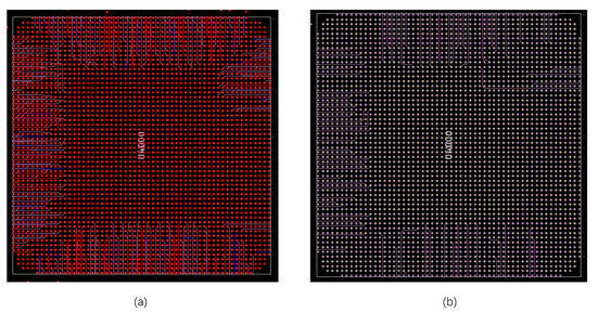
Figure 10.
Detailed routing algorithm Case5 use case GPA device experimental results diagram. (a) Multi-layer experimental result diagram. (b) Single layer experimental results diagram.
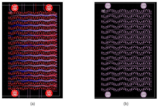
Figure 11.
Detailed routing algorithm Case5 use case SPA device experimental results diagram. (a) Multi-layer experimental result diagram. (b) Single layer experimental results diagram.
It can be seen from Table 2 that when testing small-scale PCB use cases, all three solutions show good performance, but the trial backtracking method gives the worst routing results, there are winding conditions, the routing length is long, and it takes the longest time. The linear programming method’s routing length and running time are slightly longer than those of the detailed routing algorithm, and there are local windings. When testing the medium-scale use cases, there are many windings in the trial backtracking method, which occupies the routing space of the other nets, resulting in a reduction in the routing rate, and the experimental results under different trial granularities are significantly different. The results in Table 2 are averaged. The running time of the linear programming method also increases significantly. In larger-scale test cases, the routing rate of the trial backtracking method drops sharply, while the linear programming method still gives good routing results, but the time performance cannot meet the requirements. In Case 8, the trial backtracking and linear programming methods are not counted because the running time is too long. The detailed routing algorithm has good time performance and high routing quality in small-, medium-, and large-scale use cases. It successfully completes the legalized routing of all line networks, with a routing rate of 100%.
6. Conclusions
In this paper, we treat legalized routing as an independent stage and propose a new scheme based on integer line programming suitable for large-scale, multi-device, printed circuit board design. We first constructed a plane grid diagram based on the location of obstacles and established legal routing models. Then, a legalized routing algorithm based on integer linear programming was proposed. Compared with the trial backtracking method, the routing success rate in medium- and large-scale test cases remained 100%, which meets all the design rules and applies in complex scenarios, such as SPA devices. Finally, a heuristic strategy was used to design and implement a detailed routing algorithm. Compared with the linear programming method, the time performance was greatly improved, and the routing quality was also better. The running time was about 20% that of the linear programming method, and the successful routing length was shortened by about 5% on average. The experimental results show that our solution effectively solves the legalized routing problem in ordered escape routing. It can be used in the final stage of automatic routing to obtain legal routing results and in the post-processing stage to correct routing that violates DRC. This solution has advantages and the potential for PCB automatic routing applications and has been embedded in PCB automatic routing tools. Follow-up research will consider extending this solution to bus routing modules and improving the stability of the solution to adapt to other complex and changeable routing scenarios.
Author Contributions
Conceptualization, C.C., Q.L. and J.C.; methodology, C.C., X.T., Q.L., J.C. and Z.L.; software, C.C., X.T. and Z.L.; validation, C.C. and X.T.; data analysis, Q.L. and J.C.; writing—original draft preparation, C.C. and X.T.; writing—review and editing, X.T., Q.L. and Z.L.; funding acquisition, C.C. All authors have read and agreed to the published version of the manuscript.
Funding
This research was funded by NSFC grant number 11871015, FJNSF grant number 2021J01624, and FSTILOIC grant number 2021ZR142.
Data Availability Statement
The data is unavailable due to privacy restrictions.
Acknowledgments
The authors want to thank the editor and anonymous reviewers for their valuable suggestions for improving this paper.
Conflicts of Interest
The authors declare no conflict of interest.
References
- Yan, T.; Wong, M.D.F. Recent research development in PCB layout. In Proceedings of the 2010 IEEE/ACM International Conference on Computer-Aided Design (ICCAD), San Jose, CA, USA, 7–11 November 2010; pp. 398–403. [Google Scholar]
- Shamkhalichenar, H.; Bueche, C.J.; Choi, J.-W. Printed Circuit Board (PCB) Technology for Electrochemical Sensors and Sensing Platforms. Biosensors 2020, 10, 159. [Google Scholar] [CrossRef] [PubMed]
- Lavagno, L.; Scheffer, L.; Martin, G. (Eds.) EDA for IC Implementation, Circuit Design, and Process Technology, 1st ed.; CRC Press: Boca Raton, FL, USA, 2006. [Google Scholar]
- Ho, Y.K.; Lee, H.C.; Chang, Y.W. Escape Routing for Staggered-Pin-Array PCBs. IEEE Trans. Comput.-Aided Des. Integr. Circuits Syst. 2013, 9, 1347–1356. [Google Scholar]
- Shin, H.; Sangiovannivincentelli, A. A detailed router based on incremental routing modifications-mighty. IEEE Trans. Comput.-Aided Des. Integr. Circuits Syst. 1987, 11, 942–955. [Google Scholar] [CrossRef]
- Guruswamy, M.; Wong, D.F. Echelon: A multilayer detailed area router. IEEE Trans. Comput.-Aided Des. Integr. Circuits Syst. 1996, 9, 1126–1136. [Google Scholar] [CrossRef][Green Version]
- Tzeng, P.S.; Sequin, C.H. Codar: A congestion-directed general area router. In Proceedings of the [1988] IEEE International Conference on Computer-Aided Design (ICCAD-89) Digest of Technical Papers, Santa Clara, CA, USA, 7–10 November 1988; pp. 30–33. [Google Scholar]
- Fang, J.W.; Lin, I.J.; Chang, Y.W.; Wang, J.H. A Network-Flow-Based RDL Routing Algorithmz for Flip-Chip Design. IEEE Trans. Comput.-Aided Des. Integr. Circuits Syst. 2007, 8, 1417–1429. [Google Scholar] [CrossRef]
- Ma, Q.; Kong, H.; Wong, M.D.F.; Young, E.F.Y. A provably good approximation algorithm for Rectangle Escape Problem with application to PCB routing. In Proceedings of the 16th Asia and South Pacific Design Automation Conference (ASP-DAC 2011), Yokohama, Japan, 25–28 January 2011; pp. 843–848. [Google Scholar]
- Chen, C.D.; Lin, D.S.; Wei, R.S.; Liu, Q.H.; Zhu, Z.R.; Chen, J.L. Efficient Global Optimization for Large Scaled Ordered Escape Routing. In Proceedings of the 28th Asia and South Pacific Design Automation Conference (ASP-DAC), Tokyo, Japan, 16–19 January 2023; pp. 535–540. [Google Scholar]
- Lin, S.T.; Wang, H.H.; Kuo, C.Y.; Chen, Y.; Li, Y.L. A complete PCB routing methodology with concurrent hierarchical routing. In Proceedings of the 58th ACM/IEEE Design Automation Conference (DAC), San Francisco, CA, USA, 5–9 December 2021; pp. 1141–1146. [Google Scholar]
- Chen, Z.Y.; Ji, W.Q.; Peng, Y.H.; Chen, D.T.; Liu, M.Y.; Yao, H.L. Machine Learning Based Acceleration Method for Ordered Escape Routing. In Proceedings of the 2021 on Great Lakes Symposium on VLSI (GLSVLSI ’21), New York, NY, USA, 22–25 June 2021; pp. 365–370. [Google Scholar]
- Yan, T.; Wong, M.D.F. A correct network flow model for escape routing. In Proceedings of the 2009 46th ACM/IEEE Design Automation Conference, San Francisco, CA, USA, 26–31 July 2009; pp. 332–335. [Google Scholar]
- Yan, T.; Wong, M.D.F. Correctly Modeling the Diagonal Capacity in Escape Routing. IEEE Trans. Comput.-Aided Des. Integr. Circuits Syst. 2012, 2, 285–293. [Google Scholar] [CrossRef]
- Luo, L.J.; Wong, M.D.F. Ordered escape routing based on Boolean satisfiability. In Proceedings of the 2008 Asia and South Pacific Design Automation Conference, Seoul, Republic of Korea, 21–24 March 2008; pp. 244–249. [Google Scholar]
- Jiao, F.; Dong, S. Ordered escape routing for grid pin array based on min-cost multi-commodity flow. In Proceedings of the 21st Asia and South Pacific Design Automation Conference (ASP-DAC), Macao, China, 25–28 January 2016; pp. 384–389. [Google Scholar]
- Liao, Z.P.; Dong, S.Q. A Constraint-Driven Compact Model with Partition Strategy for Ordered Escape Routing. In Proceedings of the 2020 on Great Lakes Symposium on VLSI (GLSVLSI ’20), New York, NY, USA, 7–9 September 2020; pp. 393–398. [Google Scholar]
- Tang, P.S. VLSI CAD Theory and Method; Fudan University Press: Shanghai, China, 1990; pp. 262–300. [Google Scholar]
- Gonçalves, S.M.M.; Rosa, L.S.; Marques, F.S. DRAPS: A Design Rule Aware Path Search Algorithm for Detailed Routing. IEEE Trans. Circuits Syst. II Express Briefs 2020, 7, 1239–1243. [Google Scholar] [CrossRef]
- Jia, X.T.; Cai, Y.C.; Zhou, Q.; Chen, G.; Li, Z.Y.; Li, Z.W. MCFRoute: A detailed router based on multi-commodity flow method. In Proceedings of the 2014 IEEE/ACM International Conference on Computer-Aided Design (ICCAD), San Jose, CA, USA, 2–6 November 2014; pp. 397–404. [Google Scholar]
- Jia, X.T.; Cai, Y.C.; Zhou, Q.; Yu, B. A Multicommodity Flow-Based Detailed Router With Efficient Acceleration Techniques. IEEE Trans. Comput.-Aided Des. Integr. Circuits Syst. 2018, 1, 217–230. [Google Scholar] [CrossRef]
- Kahng, A.B.; Wang, L.T.; Xu, B.Q. TritonRoute: An Initial Detailed Router for Advanced VLSI Technologies. In Proceedings of the 2018 IEEE/ACM International Conference on Computer-Aided Design (ICCAD), San Jose, CA, USA, 5–8 November 2018; pp. 1–8. [Google Scholar]
- Li, Y.; Zhang, H.; Liang, X.; Huang, B. Event-Triggered-Based Distributed Cooperative Energy Management for Multienergy Systems. IEEE Trans. Ind. Inform. 2019, 8, 2008–2022. [Google Scholar] [CrossRef]
- Gurobi Optimizer. Available online: http://www.gurobi.com (accessed on 10 July 2023).
Disclaimer/Publisher’s Note: The statements, opinions and data contained in all publications are solely those of the individual author(s) and contributor(s) and not of MDPI and/or the editor(s). MDPI and/or the editor(s) disclaim responsibility for any injury to people or property resulting from any ideas, methods, instructions or products referred to in the content. |
© 2023 by the authors. Licensee MDPI, Basel, Switzerland. This article is an open access article distributed under the terms and conditions of the Creative Commons Attribution (CC BY) license (https://creativecommons.org/licenses/by/4.0/).