Article

Empowering Accessibility: BLE Beacon-Based IoT Localization

by
Patryk Pyt
,
Kacper Skrobacz
,
Piotr Jankowski-Mihułowicz
*,
Mariusz Węglarski
* and
Kazimierz Kamuda
Department of Electronic and Telecommunications Systems, Rzeszów University of Technology, ul. Wincentego Pola 2, 35-959 Rzeszów, Poland
*
Authors to whom correspondence should be addressed.
Electronics 2023, 12(19), 4012; https://doi.org/10.3390/electronics12194012
Submission received: 24 August 2023 / Revised: 16 September 2023 / Accepted: 21 September 2023 / Published: 23 September 2023
(This article belongs to the Special Issue Emerging Trends and Challenges in IoT Networks)

Abstract

:
The Internet of Things (IoT) localization empowers smart infrastructures of buildings to deliver advanced services to users leveraging mobile devices. In this context, in order to enhance the mobility of people with disabilities on the university campus, a Bluetooth Low Energy (BLE) beacon-based indoor system was developed. Particular emphasis was placed on selection of the beacon for the designed application, which was performed on the basis of the energy demand characteristics at the assumed power settings and time intervals of the emitted signal. The paper also focuses on various concepts of transmitter deployment inside buildings of the campus in order to demonstrate possible configurations in which the IoT localization will work correctly. Based on experimental determination of the signal strength reaching users’ mobile devices, the best arrangement of the system was proposed. However, the dependence of the calculated distance between the interrogated beacon and the mobile device as a function of the received signal strength is a non-deterministic function of many factors; thus, only an approximate position can be designated on the performed measurements. Nevertheless, the BLE beacon-based system, supported by additional localization algorithms integrated into the user’s mobile software, can be useful for the applications in question.

1. Introduction

Nowadays, the challenge of locating devices using various types of wireless signals is rapidly growing as a key concern in IoT (Internet of Things) systems [1,2]. The determination of object position holds great potential for providing additional or alternative services while ensuring freedom of movement, enhancing overall security, and more. The significance of precise indoor localization is on the rise given the growing prevalence of AI (Artificial Intelligence) reality, healthcare and personal monitoring, inventory management, and various applications reliant on accurate indoor positioning [3]. However, there is currently no commonly accepted standard that facilities the implementation of the localization process depending on the type of system and the users’ expectations [4].

1.1. Indoor IoT Localization

In a typical indoor localization system, the primary component of the architecture comprises a management center, which may be either centralized or distributed, along with a properly shaped network of wireless nodes/devices (which includes so-called sensors, access points, base stations, tags, beacons, etc.). The used technologies differ in terms of the accuracy of position determination, the complexity of the implemented process, outlays on infrastructure and/or the need to develop appropriate databases and specific algorithms to support the localization efforts [5].
Taking into account the needs of the designed application dedicated to supporting disabled people in quickly reaching building rooms, special emphasis was placed on analyzing the possibilities of using mobile phones. Since these devices are widely used by students, they are ideal as guides on large university campuses. Of course, currently every mobile phone is equipped with a GPS (Global Positioning System) system, which, as is commonly known, does not work in closed spaces [6]. Cellular network triangulation also does not work precisely in such conditions [7]. The possibility of using the internal sensors of the mobile device including accelerometers, gyroscopes, and magnetometers is another good solution for relative navigation with regard to a known reference point [8,9]. This solution is a perfect complement to any navigation system when the availability of the base signal is limited. Ultimately, there are two solutions that could be suitable for building the application in question: Bluetooth Low Energy (BLE) and Wi-Fi access points. Both technologies have their own advantages and limitations [10]. The main benefit of Wi-Fi localization is the high strength of signals and their availability in the case of a properly configured network. Moreover, the network is accessible both inside and outside in the immediate vicinity of buildings. However, in order to ensure sufficient precision in navigation, it is necessary to expand standard installations, which is very expensive and requires access to the power supply grid. On the other hand, BLE beacons are designed to be extremely power-efficient, making the system suitable for implementing in battery-powered devices such as smartphones and IoT sensors. They are well-suited for applications that require high accuracy in determining proximity or presence within a limited range. Setting up a BLE beacon network is generally simpler and more cost-effective than deploying Wi-Fi access points. BLE beacons are small, easy to install, and require minimal configuration. An even better solution in terms of costs and energy savings would be to replace BLE beacons with RFID transponders [6,11]. Unfortunately, mobile phones are only equipped with an NFC (Near-Field Communication) reader/writer that operates in the high frequency (HF) band. To read the tag, the reader must be placed in close proximity to it. Although systems operating in the ultra-high frequency (UHF) band are still being developed, commonly used phones do not have the ability to search for these tags.
One of the simplest mechanisms for approximating localization in any radiofrequency (RF) based system is the concept of so-called “nearest node”. This concept involves the use of multitude simple transmitters that emit radiofrequency signals, like BLE beacons [12], RFID (Radiofrequency Identification) tags [13,14], visible light communication [15], etc. The moving object that is equipped with an RF receiver can recognize the signal from the closest source, and in this way, can gain information about its position. The main advantage of this method lies in its simplicity of implementation. It eliminates the need for using complex algorithms and advanced computational resources. Almost all wireless or cellular systems can be adapted to this technique with minimal expenses. However, the straightforward nature of this concept comes with certain limitations. In the case of a dense network of reference nodes, the mobile device could potentially detect multiple transmitters, including those located at a considerable distance. The detection range is influenced by the conditions of electromagnetic wave propagation. Consequently, the precision of tracking is compromised, making this technique suitable only for uncomplicated applications where high accuracy is not required.
The IoT localization can be achieved with a significant enhancement in accuracy by incorporating additional mechanisms and computational algorithms [16,17]. The most popular is triangulation. The topographic relationships between three or more neighboring nodes or other reference points available in the system are used to determine the location of monitored objects. If the coordinates of the nodes in Cartesian space are known, then the standard information obtained during network scanning and the measurement of the RSSI (Received Signal Strength Indicator) is sufficient to address localization tasks. The effectiveness of this technique certainly improves as the number of nodes participating in the localization process increases [18].
Although other parameters of the transmission path can be measured in multilateration systems (e.g., Time of Arrival (ToA) or Time Difference of Arrival (TDoA)), the mechanism of determining the RSSI coefficient is most often used in common radiocommunication devices [19,20]. Assessment of the strength of the incoming signal is easy to implement in modern receiving circuits; however, the obtained values are affected by many attenuating factors present in the radio channel. Having knowledge of propagation models, transmitted output power, cable losses, antenna gain and potential interferences on the radio path can significantly enhance accuracy of the localization. Unification in the assembly, housing, antennas, and other elements of the devices used in the network of reference points, if possible, also positively affects the effectiveness of the results achieved.
Due to the unpredictable nature of attenuation in the radio channel, the RSSI measurement technique is often supplemented by the use of the so-called RF patterns, which is known as fingerprinting [21,22]. The core concept behind the fingerprinting method involves the use of an intelligent algorithm that enables validation of the estimated RSSI coefficient. This approach is based on the assumption that each tracked device has a unique RF signature (characteristic attenuations and duplications of the signal, the number of available propagation paths, etc.) that can be compared with the prepared database. This methodology can be entirely integrated in software, which essentially reduces the cost of its implementation and facilitates algorithm enhancements without necessitating hardware modifications. Such a mechanism demonstrates remarkable efficacy within difficult and diverse propagation scenarios, particularly within spaces characterized by dynamically changing number and types of obstacles (people, windows, doors, cars, etc.).
Of course, there are numerous methods to enhance the accuracy of object location within the network structure of navigation points, and this topic has been the subject of many publications [23]. It turns out, however, that simple RSSI measurement algorithms are sufficient for creating an effective information system about rooms in a building. Therefore, the RSSI-based measurement method is attractive for many simple implementations, as the costs are relatively low. Ultimately, the proper selection of device types, and a judiciously allocated expenditure on infrastructure in relation to the expected outcomes (accuracy of location enough for a given application), leads to the dynamic development of WLBS (Wireless Location-Based Services) solutions in real-world scenarios.

1.2. Investigation Assumptions

The research aimed to create an intelligent guide system for people with disabilities staying on the extensive university campus encompassing more than 25 buildings. The primary objective was to choose a right radio device that could facilitate navigation tasks in the comprehensive information service for locating users’ position, with an emphasis on minimizing user efforts and investments as much as possible.
Hence, from the technical side, it was assumed that the system would be based on a network of beacons deployed in key points of utility areas and on a dedicated application launched on mobile devices (e.g., smartphones) operating under Android or iOS platforms. Beacon is a small, portable and discreet battery-powered radio device that broadcasts unique digital information (usually a digital identifier) at specified intervals. If it operates in the Bluetooth Low Energy (BLE) standard, it can be recognized by commonly available mobile devices (smartphone, tablet, etc.). It can serve as a source of a signal that triggers a specific action in the receiving device or as an identifier of desired information stored in a database, etc. It can also be used to determine the location or movement path of an object to which it is assigned.
The IoT system, which relies on unique information read from the beacons in real time and has access to the university database, can provide disabled users with all the necessary information about the desired service and the identified place. In addition, if the mobile device receiver is able to read the signal from several beacons at the same time, it will be possible to automatically locate and determine the user’s location on the virtual map of the university campus. Very often, appropriate functions enabling the implementation of the selected localization method are made available in the commissioning software offered by the beacon suppliers.
At the stage of preparing the initial assumptions, it was decided to seek the most cost-effective and low-maintenance products due to the large number of beacons required for the intelligent guide system. In addition, the device should meet the following requirements:
  • It has to be compatible with iOS and Android systems—unfortunately, most beacons are compatible with only one system, and often, such information is not disclosed in the manufacturers’ specifications;
  • It can be placed both inside and outside buildings—suitable waterproof and vandal-proof housing has to be provided for adequate protection;
  • It should feature an easily replaceable battery and facilitate the maintenance process;
  • It should integrate an intelligent transmitter—the ability to adjust the level of emitted power and the interval of transmitted signals can significantly prolong the operational lifespan;
  • SDK (Software Development Kit) libraries for the Android and iOS operating systems should be available.
A characteristic feature of public utility facilities is the presence of large, common and open spaces, additional obstacles in the form of floor level variability, irregular walls, mezzanines, loggias, staircases, and permanent obstacles with many metal components affecting the propagation of the electromagnetic waves. It results in a significant complication of the propagation structure and disrupts the process of location determination. The impossibility of placing beacons at a constant height has an additional negative impact on the ambiguity of the level of received signals in relation to the actual localization of nodes. Consequently, the advanced software algorithms have to be used for analyzing acquired data (e.g., fingerprinting method), and it is associated with a huge amount of additional work, costs and extension of the project implementation time.
However, the application prepared especially for the needs of the project implements basic localization methods available in standard libraries dedicated to typical operating systems (Android and iOS). The main reason for this approach is the fact that the application for navigation in university facilities is to be available to a wide group of devices operating in a diverse architectural and propagation environment.
The paper contains a description of the beacons used to mark the buildings of the university campus, their configurations and the method of mounting. The characteristics of the current consumed by the selected beacon are determined, and its energy demand is estimated for the selected power settings and time intervals of the emitted signal. Verification of the system’s operation is also carried out for various concepts of placing transmitters inside the buildings. Finally, practical implementation demonstrates possible configurations in which the intelligent guide system works correctly.

2. Characteristics of Major Components

The major idea behind the project was to create the IoT localization system that could be used by every student without the need to purchase additional equipment. Therefore, it was assumed to use mobile devices that are compatible with iOS (from version 7) and Android (from version 4.0) operating systems.

2.1. Characteristic of Used Beacons

To meet the primary requirement, the chosen transmitting device has to incorporate an appropriate chip, i.e., nRF51822, nRF52832, CC254x, and CC2640. Parameters of the mentioned chips taken into account at the stage of preparing the project assumptions are listed in Table 1.
Based on the analysis of beacons available on the market, two sample products were designated in order to present their properties in terms of their possible use in the designed application (Table 2). Particular emphasis was placed on selection of the beacon according to the energy demand characteristics at the assumed power settings and time intervals of the emitted signal. Both devices are based on the BLE 4.x NRF51822 chip. The chip is designed upon a 32-bit Cortex-M0 platform and includes 16 kb RAM along with 256 kb FLASH. It also meets the requirements of iBeacon License CE Regulations (EN300328, EN301489, EN60950, EN62479) as well as FCC Regulations (FCC Part 15).
As seen from Table 1 and Table 2, the range of beacon offerings is quite extensive, and the choice of a specific product is primarily influenced by how easily it can be adapted to the established requirements within the developing IoT application. Since basic parameters, such as the time interval between successive signal transmissions, transmitter power, or identification numbers can be configured by the system administrator, both devices are suitable for conducting experimental research. The main advantage of GT-DKBY-BLE by Global Tag is that it is prepared for mounting on flat surfaces/walls, both for outdoor and indoor use. Moreover, it can be equipped with a temperature or humidity sensor or accelerometer, which could be useful in the planned next stage of IoT system development. For configuring operational parameters, the BluEpyc BE-BLEG-D-E Bluetooth network gateway and the Beacony Encoding Tool 5.1 software provided by the beacon manufacturer can be utilized.

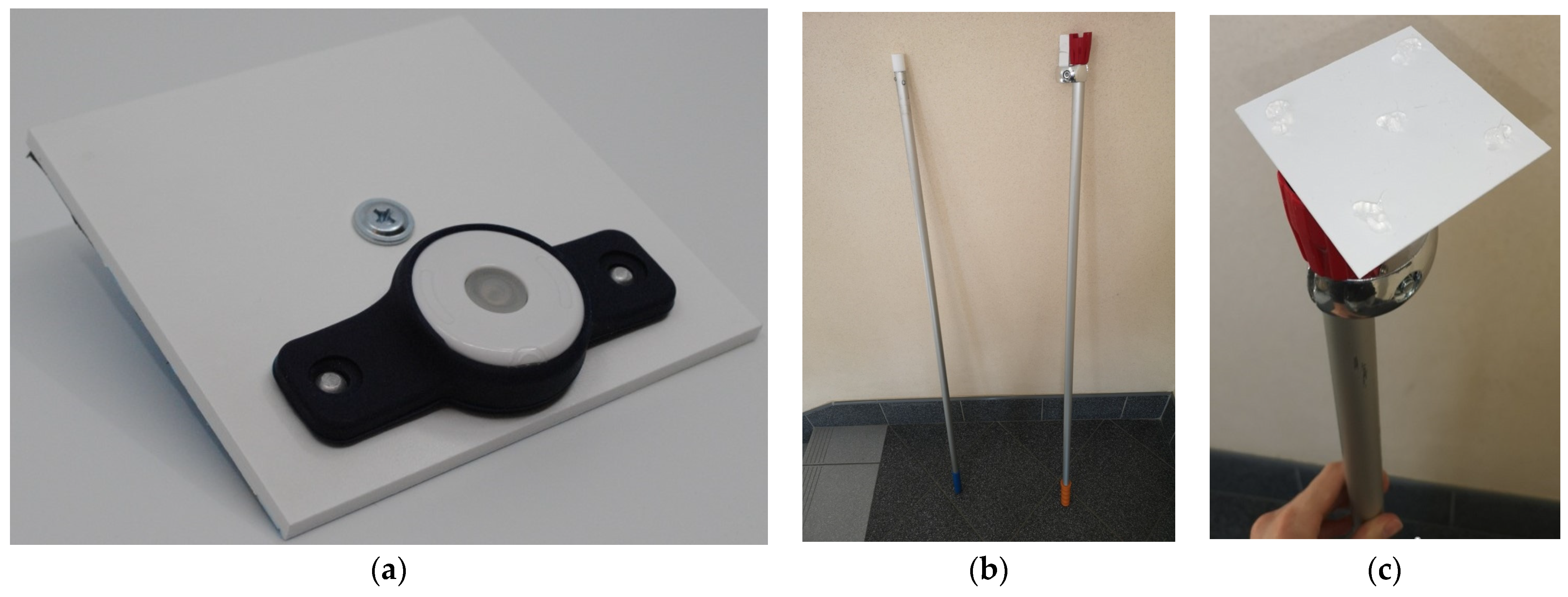
2.2. Beacons Assembly in University Campus

To establish the network of reference points for the IoT localization infrastructure, it is necessary to fix beacon rubber clamps to the walls or ceilings, at a substantial height, within a space that is inaccessible to future users or potential malicious attacks. Moreover, beacons should be installed away from obstacles that could disturb the electromagnetic waves, such as moving objects or people, pipes, ventilation components, routers, cameras, smoke detectors, wire installation, etc. It is also important to consider that occasional service tasks, such as battery replacement, will be required. Thus, the assembling process has to be precisely thought out and prepared in detail in order to avoid unnecessary damages and reduce maintenance costs. For instance, assembling beacons to coffers allows not interfering with the surfaces of walls or ceilings, and cassettes, although they are susceptible to damage, can be easily replaced or moved into another position.
To enhance the effectiveness of the assembly process, certain facilitates may be proposed. The rubber housing of the beacon may be permanently attached to the plastic plate (Figure 1a) that is easily adhered to a given surface. This board may also serve as a base for any subsequent modifications of the transmitters, such as the incorporation of sensors or photovoltaic modules instead of lithium batteries.
Since the recommended mounting height is at least 2 meters (Section 3.2), a specialized tool was developed to enable installers to quickly attach multitude of transmitters without the need to use a ladder (Figure 1b,c).

3. Preliminary Investigations

In order to prepare for the examination of the BLE beacon-based IoT localization system, some preliminary tests need to be performed. The most important one is to estimate the dependence of the beacon’s activity duration on the set operational parameters, and next, the availability of the transmitted signal has to be checked in various system operating conditions.

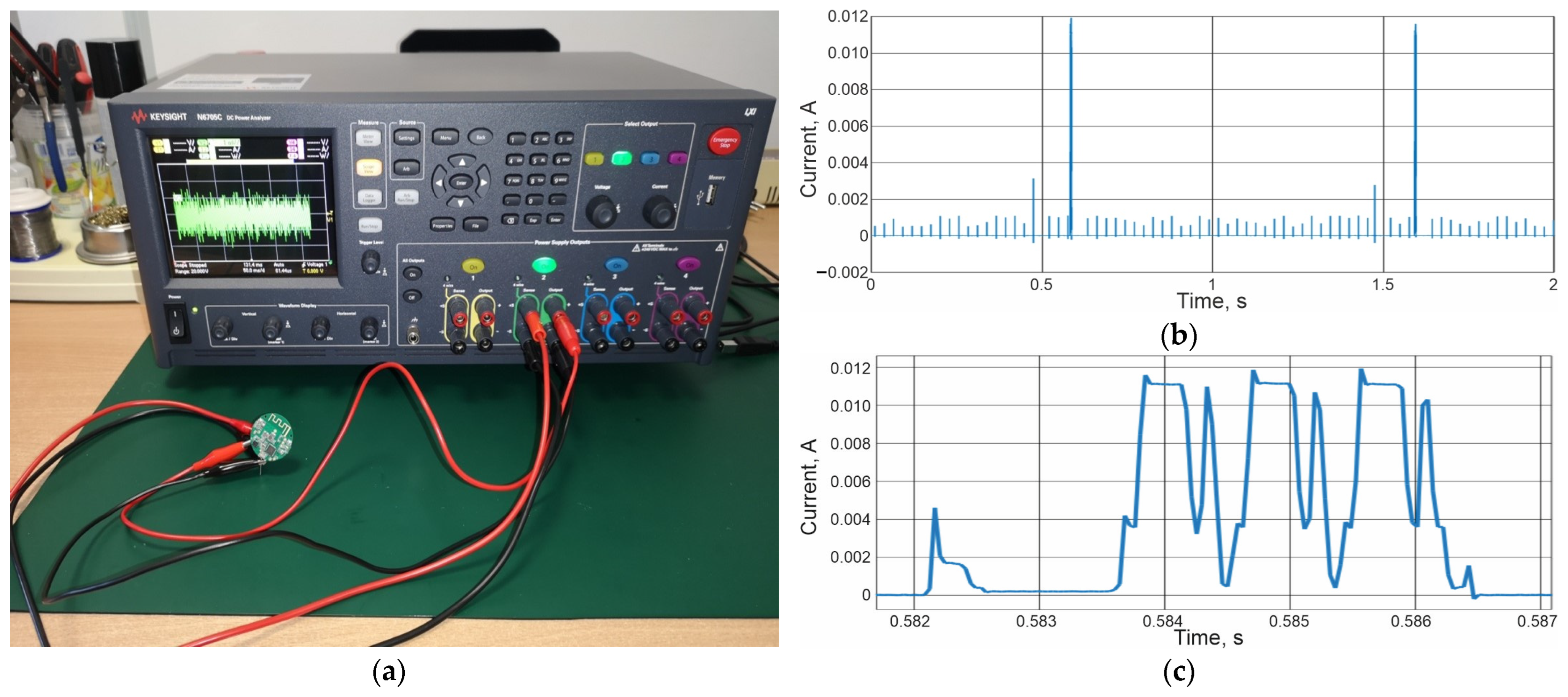
3.1. Device Operating Time

Each beacon is powered by a single lithium battery with a voltage of 3 V and a capacity of 235 mAh. In order to estimate the device’s operational duration, measurements were taken for the current consumption in the transmitter set to 0 dBm for the output power and to 1 s for the time interval.
The measurements were conducted using the Keysight (Santa Rosa, California, USA) N6705C DC power analyzer, which provided a constant voltage of 3 V to the transmitter and recorded the current flow. The measurement setup along with the characteristics of the current consumption are shown in Figure 2.
Most of the time, the beacon is in sleep mode with the current load of approximately 4.5 µA despite set parameters of signal transmission. The current peaks, as shown in Figure 2b, are related to the operations carried out by the device in the active mode. The highest current consumption Imax of about 12 mA occurs during transmission, which lasts about 4 ms (Figure 2c). The average current Iav is equal to 28.2 µA (measured by Keysight N6705C DC). The working time of the beacon on one battery can be expressed by the formula:
b l = b c I a v = 235   m A h 0.0282   m A = 8333   h
where bl means the operational time of the beacon on one battery, bc—battery capacity, and Iav—mean value of current consumption. Hence, the beacon can work for approximately 347 days between successive battery changes. In Table 3, calculations for other setups are presented. Evidently, the configure parameters of the transmitter have a decisive influence on its runtime. In addition, to a small extent, the average current load will also depend on the transmission duration. In this case, the crucial factor is the number of bytes in the Advertising Packet (set to 30 bytes for the iBeacon protocol).
It should be noted that the battery replacement process is time-consuming, and it generates both costs and waste. Therefore, it is advisable to equip the beacons with their own renewable energy sources, e.g., in the form of photovoltaic panels. This approach would transform the system into a self-maintaining one that is more cost-effective and free of waste produced by disposable batteries.

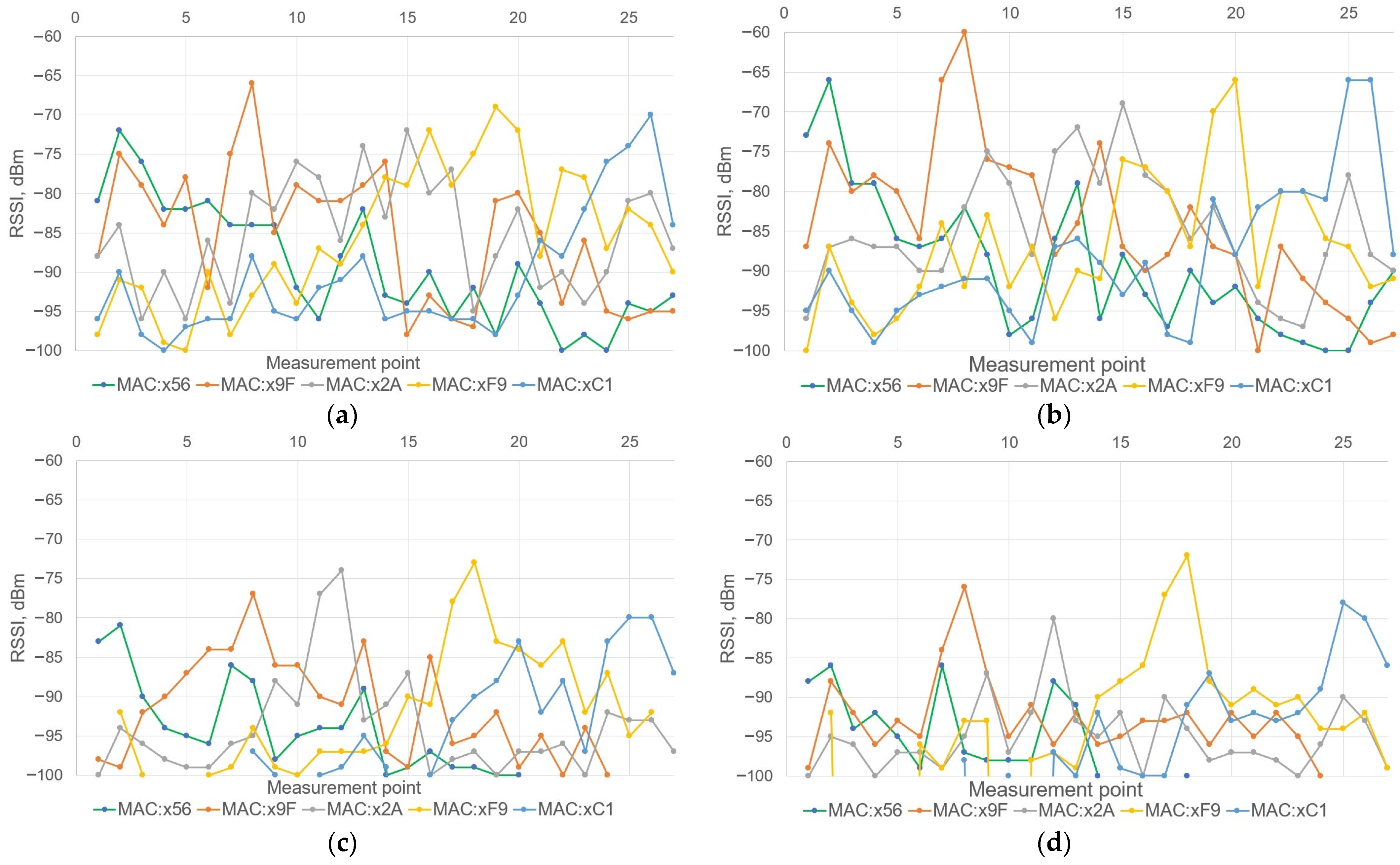
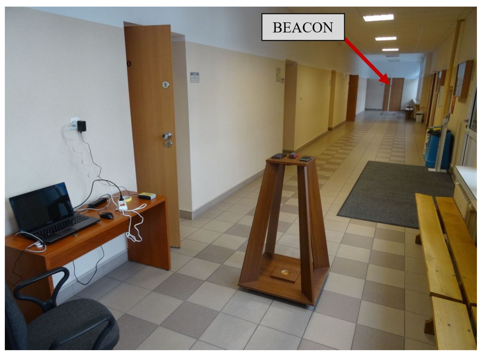
3.2. Indoor Signal Strength Measurement

The signal strength reaching the mobile phone located at varying distances from the beacon was measured in the first stage of the scheduled research (Figure 3). The experiment was performed for two mounting heights and three transmitter power levels at the time interval of 1 s.
The beacon was attached to a plastic post in such a way that its height could be adjusted without disassembling it. The plastic post had no impact on the electromagnetic waves emitted by the transmitter. The mobile phone was positioned horizontally on a wooden stand during the measurements. Two phones were used in the experiments: a SONY (Kōnan, Minato, Tokyo, Japan) Xperia XZ2 H8324 with Android 10, and HUAWEI (Shenzhen, China) Honor KIW-L21 with Android 6.0.1. The measured value was determined as the average of five RSSI measurements taken by each of the phones.
The mobile phones were placed on the stand at a height of about 100 cm above the floor, which corresponds to the approximate height during their regular usage. The beacon was suspended on the post at heights of 160 cm and 200 cm above the floor. Transmitter power was configured at 0 dBm, −23 dBm and 4 dBm. The given distances were measured from the center of the mobile phone to the beacon post. The polynomial trend lines of the third degree calculated for measured values of the signal strength are marked in black color in Figure 4. In all cases, as the distance between the transmitter and the phones increases, the signal strength decreases. On the other hand, increasing the height of the beacon suspension reduces the dispersion of the results read from both phones. Various environmental influences, such as reflections of the transmitted signal or electromagnetic waves generated by other sources, can lead to interference in receiving the signals from the beacon.
At the lowest transmitter power of −23 dBm, the measured signal strength, even at close range, falls below −85 dBm. Beyond a distance of 9 m, the mobile phones began losing the signal, as it become unstable along the entire length. Beyond distances exceeding 15.6 m, no phones were able to receive the signal anymore. With these beacon settings, it is advisable to use them to mark objects that the phone user needs to approach closely.
At the maximum transmitter power of 4 dBm, the signal exhibits greater stability when compared to all previous cases. The range is maximized and is over 21 m. Despite many advantages, this higher transmitter power significantly reduces battery life.
To sum up, beacons should be placed as high as possible in the smart guidance system designed for people with disabilities. Moreover, maintaining a distance of at least several centimeters from the ceiling and other fixed installations is advised to avoid reflections. This approach improves the signal stability, eliminates disruptions due to potential obstructions by objects (mainly moving people), and discourages potential theft or unauthorized tampering.

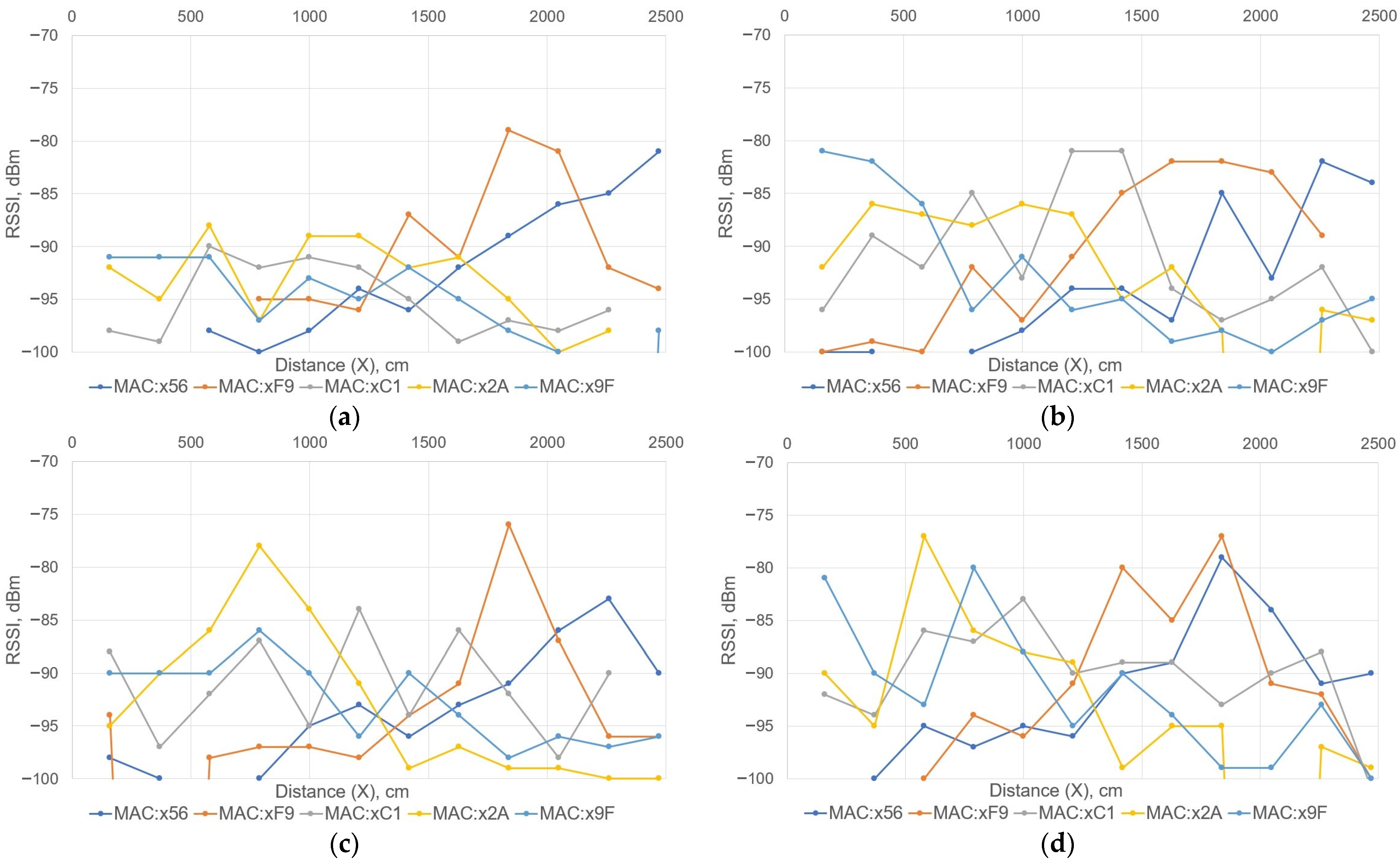
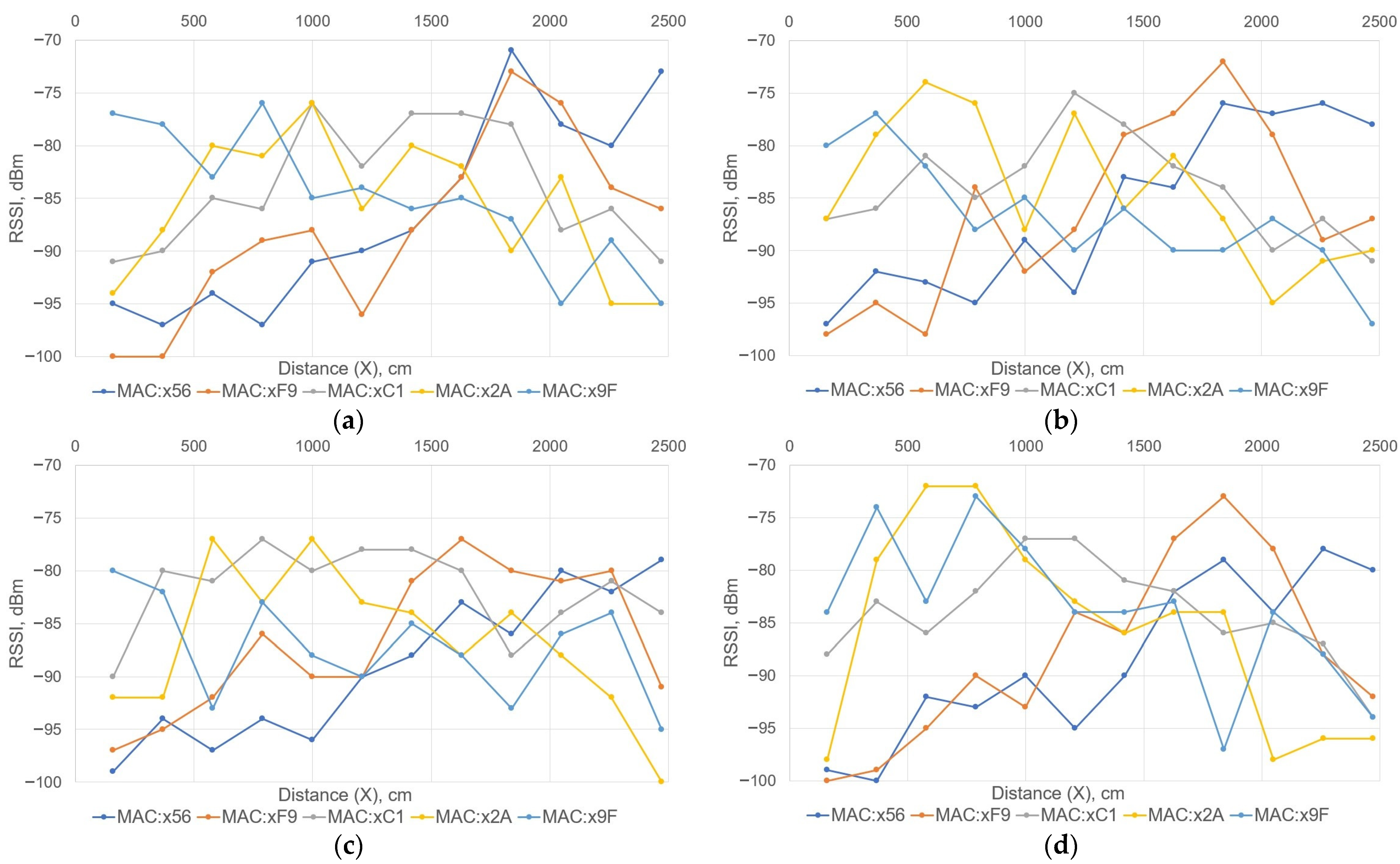
3.3. Node Network Signal Strength Measurement

To evaluate the effectiveness of object location in relation to the network of reference points, five beacons were placed in a building on the university campus. These devices were attached to various points on the walls of the test corridor at a height of over 2 m (as discussed in Section 3.2). The map of the hall with marked locations of the transmitters along with their coordinates and the last two digits of the beacons’ MAC (Media Access Control) address is depicted in Figure 5. Measurements were performed for two power settings in the transmitters, 0 dBm or −6 dBm, and with the time interval of 1 s between successive signals. The points where the signal strength received by the mobile phone was measured lie on one plane parallel to the floor surface, forming two lines (Y = 134 or Y = 225) along the corridor (blue lines in Figure 5). The HUAWEI Honor KIW-L21 mobile phone with Android 6.0.1 was used in the experiment. The mobile phone was placed on a wooden base at a height of 103 cm above the floor surface. Measurements were made with the phone in both the vertical and horizontal position.
The values of RSSI signals, read by the mobile phone placed at selected points in the corridor (blue lines Y = 134 or Y = 225), are shown in Figure 6. The user’s position can be estimated on the basis of the known locations of all five beacons. As the phone approaches a given beacon, the signal received from it becomes stronger.
The case when the user moves along the interior wall (Y = 225), where doors to rooms are located, is presented in the first two graphs (Figure 6a,b). It is noticeable that changes in the phone’s position, and subsequently its antenna’s orientation, result in variations in the received power level. However, it remains possible to estimate the object’s position in the IoT system localization.
When the user moves along the side closer to windows of the corridor (Y = 134; Figure 6c,d), it becomes evident that the power level of received signals is higher for the beacons located on the window side. The orientation of the phone also affects signal reception, but it is still possible to estimate which of the transmitters is closest to the user.
The level of received signals at measuring points decreases after reducing the power of the transmitters to −6 dBm (Figure 7). Nevertheless, it is still possible to estimate the distance of the phone from a given beacon. However, it is more difficult especially for the case when the user moves along the side closer to the windows (Y = 134; Figure 7c,d). For example, F9 and 2A transmitters are placed 12 m apart from each other on the wall with windows. Moving from the node F9 to 2A, there is a decrease in the power of the signal received from the first device and an increase from the second beacon. On this basis, the current user location can be determined. The power level of signals received from beacons located on the interior wall (nodes 9F, C1 and 56) remains relatively stable. This lack of significant fluctuations is due to the fact that the phone does not approach a given beacon, unlike in previous scenarios when the user moved closer to the wall (Y = 225).
To sum up, reducing the transmitter power from 0 to −6 dBm definitively extends battery life. However, as a consequence, the received signal becomes unstable and disappears completely at longer distances. The signal reception is also influenced by altering the phone’s spatial position. Nevertheless, the variations in signal strength levels due to different phone antenna positions are comparable to differences caused by other factors, such as different phone models, changing the position of surrounding objects (e.g., opening and closing doors or windows, moving people), or even the way in which the phone is held. In such a situation, the determination of the users’ position within the building is still possible by analyzing mutual proportions of signals strength received from beacons with precisely known locations.
The results of RSSI measurements obtained at point P1 (Figure 5), located next to the entrance door to the corridor, are presented in Table 4. During the experiment, the transmitter’s output power was configured at either 0 dBm or −6 dBm. The point P1 was positioned 180 cm away from the closed door and 65 cm away from the guardrail along the stairs (Figure 5). The difference in the results of signal strength measurements between the horizontal and vertical position of the phone is small. At 0 dBm transmitter power, all received signals were below −85 dBm. The phone did not receive a signal from the farthest beacon located on the same wall as the door. In the case of the transmitter power set to −6 dBm, the RSSI of all received signals was below −88 dBm, and the signal from the two most distant beacons did not reach the phone at all.
The results of RSSI measurements obtained at points P2, P3 and P4 (Figure 5), located in one of the rooms, are presented in Table 5. The points are positioned in the distances of 100, 200 and 300 cm away from the room’s door. The beacon with MAC number 56 is moved to the room above the windows line to the position 56′ (at the height of 240 cm).
The RSSI values received from beacons placed in the corridor remain below −90 dBm. As expected, after reducing the transmitter power, the RSSI levels decrease further. It is worth noting that in some cases, the signal from the beacons localized on the wall opposite to the door disappeared completely even though these beacons are in a direct straight line with the mentioned door.

3.4. Signal Strength Measurement in Stairwell Scenario

The received signal strength was also measured for the case of the stairwell. The mobile phone was placed at a height of 130 cm from the ground, and the test points are indicated in Figure 8 with blue crosses. Five beacons were installed on subsequent floors and mezzanines at a height of 240 cm above the floor surface. The power level of the transmitters was set to 0 dBm and −6 dBm and with the time interval of 1 s between successive signals. The HUAWEI Honor KIW-L21 mobile phone with Android 6.0.1 was used in the experiment.
The results of the measurements of the signal strength received by the mobile phone from five different beacons are summarized in Figure 9. It can be seen that the user’s location can be determined based on the RSSI readings. However, the position of the phone also affects the signal strength, but it is comparable to the influence of other factors, such as the arrangement of objects in the stairwell, the user’s orientation, the way the phone is held (whether held entirely with the whole hand or by its corner), as well as the presence or absence of a phone cover, etc.
If the transmitter power was configured to −6 dBm (Figure 9c,d), the strength of the received signals dropped significantly, resulting in the absence of signals from certain beacons. Nevertheless, this change does not worsen the localization aspects, as nodes situated in close proximity to the mobile phone are more easily identifiable.

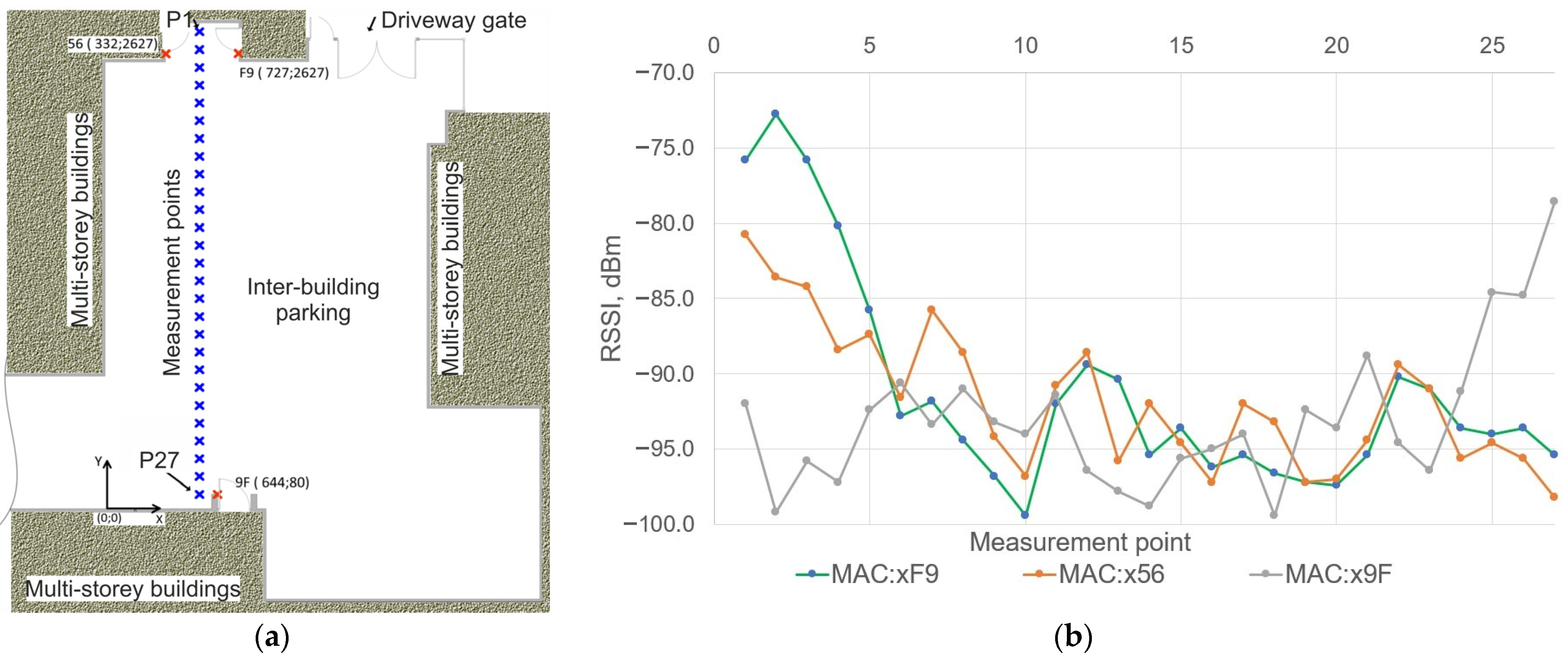
3.5. Outdoor Signal Strength Measurement

In the study, another aspect involved gauging the RSSI signal strength outdoors, aiming to validate the effectiveness of IoT localization while moving between various buildings across the university campus. Three beacons were mounted on the outer walls of the buildings at a height of 210 cm next to the entrance door (Figure 10a). The power of the transmitters was set to 0 dBm with the time interval of 1 s between successive signals. The HUAWEI Honor KIW-L21 mobile phone with Android 6.0.1 was used in the experiment. The phone was placed at a height of 130 cm above the ground at selected points between buildings (Figure 10a). In each case, the phone was in the horizontal position relative to the ground.
The dependences of the signal strength in the selected points of the inter-building parking are presented in Figure 10b. As the phone is placed closer or farther from the beacons, the recorded RSSI values increase or decrease correspondingly. In the middle of the parking area (P13 and P14), values of RSSI factor are in the range of −90 to −100 dBm. Since the same transmitters are used, and their parameters are configured identically to those in the previous scenarios, the strength of received signals outdoors is weaker compared to the power of signals received inside the building. This occurs because there is an electromagnetic wave multipath effect indoors, which results in a stronger received signal. In the free space of the parking area, however, the electromagnetic waves emitted by the transmitters propagate into space, and a smaller portion of them reaches the receiver.

4. System Implementation

The knowledge gained from the research discussed in Section 3 was used to implement the IoT localization system on the university campus (Figure 11a). The IoT system is dedicated, in particular, to supporting people with disabilities so that they can quickly and accurately locate the places they are looking for. To achieve this, it was necessary to deploy several thousand beacons in every building on the campus. Before commencing the implementation of the node network, the effectiveness of the system was tested in two different arrangements of transmitter locations: Case I—beacons positioned directly above room doors; Case II—beacons evenly positioned along the hall.
Prior to installation, the following beacon operating parameters were configured: the output power 0 dBm and the time interval 1 s. These configurations allow reaching a signal range of up to 10 m, which was confirmed in the preliminary tests. The results of the RSSI index measurements are summarized in Section 4.1 (for Case I) and Section 4.2 (for Case II). The network gateway Bluetooth BluEpyc BE-BLEG-D-E connected to the mobile PC with Beacon Encoding Tool 5.1 software tool was used in the tests for configuring beacons and conducting RSSI measurements.

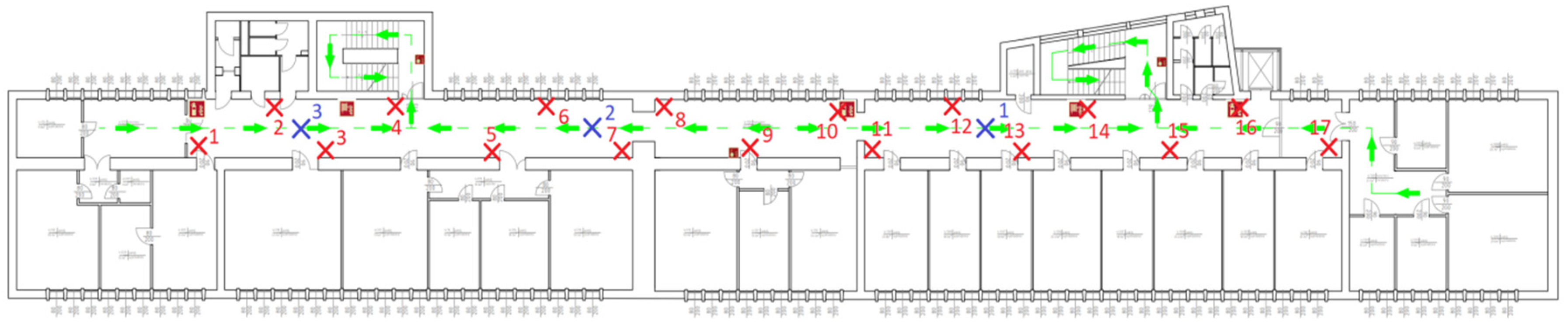
4.1. Beacons Positioned Directly above Room Doors

The first approach to node network organization involved attaching beacons directly above the doors leading to all rooms (Case I). The rationale behind this positioning is based on the principle that the signal strength from a specific node increases as the user’s proximity to the transmitter becomes closer. Consequently, positioning the transmitter at the door enables the software on the mobile device to compute the distance from the user to the desired destination. Furthermore, by measuring the signal strength from other beacons at the remaining entrances, it becomes possible to enhance the precision of estimating the user’s exact location. It is worth highlighting that this method of beacon placement greatly simplifies the procedure of assembling the node network and subsequently transferring it to a virtual application. This is due to the fact that determining only the beacon’s position relative to the door is sufficient for this purpose (Figure 11).
The recorded RSSI values (Table 6) obtained from beacons in the prepared node network (Figure 12) provide a clear means to accurately estimate the user’s location within the corridor in the majority of instances. However, some doors are too close to each other, which results in a small difference in the strength of the signals coming from the adjacent beacons. This disparity may potentially lead to the misinterpretation of the relative positions of the nodes. Placing transmitters next to doors that are spaced closely, less than approximately 2 m apart, may lead to these distortions. In such a case, it is advisable to install the beacon solely at one door, and the required shift should be calculated in the algorithms of the application installed on the mobile phone.

4.2. Beacons Evenly Positioned along the Hall

The second tested configuration involved the uniform distribution of transmitters along the corridor (Case II, Figure 13). For the experiment, a corridor with a layout comparable to the previous one was selected. In this case, the beacons were evenly installed on both sides of the corridor, maintaining an approximate distance of 6 m between adjacent nodes.
The beacons were suspended at a height of about 2.4 to 3 m, taking into account the technical and economic considerations discussed in the previous sections. In the course of the experiments, it became evident (compare Table 6 and Table 7) that an even distribution of the transmitters yielded superior results compared to placing them solely near the door. Using straightforward algorithms for assessing the signal strength values within the software, it becomes feasible to unequivocally ascertain the user’s current location relative to the nearest door.

4.3. Summary of Application Tests

The comparison of the two tested concepts is presented in Table 8. The distance between any two neighboring beacons should be maintained at more than 6 m (assuming the beacon types and their parameters selected for the experiments). Keeping this requirement, the designated localization space is divided into smaller zones, each of which is allocated to a single node. Consequently, the strength of the signal from adjacent beacon within each zone can be easily selected as the maximal recorded value. The exception is the border of these zones, where the distances from the receiver to several neighboring transmitters are similar. At these locations, the RSSI values of signals from different transmitters are also at a comparable level. However, using simple computing algorithms, the user’s position can be easily estimated. But the problem arises when beacons are mounted in too small distances. It may potentially lead to distortions in the interpretation of the users’ relative positions. On the other hand, the distance between two adjacent beacons should not be greater than 10 m. This is the distance from which a stable signal can be received. At a greater distance, the signal is not stable, and its power is very low: about −95 dBm. Determining the location of the receiver in a given area requires at least three stable signals from distinct beacons. As a rule of thumb, the height of the transmitter should be lower than the distance between adjacent transmitters.
In order to overcome obstacles of any kind, the beacons have to be installed at the significant height above 2 m. Nevertheless, to thoroughly address this issue, multiple scenarios should be analyzed, taking into consideration various concepts of transmitter deployments inside buildings (Table 8). In all cases, signal attenuations occur sporadically and temporarily when the movement is fast and occasional, or permanently—in crowded conditions. However, the navigation software relies on localization algorithms that search for the strongest signal source based on the relative levels of transmitted electromagnetic waves. Therefore, the problem is not overly significant; assuming that the user has to be at a short distance from the beacons, the beacons are installed at a relatively high altitude as well as the movement area and the choice of possible directions are quite limited, and the user moves within a strictly defined environment.
According to the assumptions of the BLE Beacon-Based IoT Localization system, the selected building of the campus has to be reached using other location systems such as GPS. However, the problem of indoor GPS location coverage is widely known, and therefore, there is a need to explore other solutions. After reaching at least the entrance door of the building (or courtyard, entrance gate, etc.), the user should be within the range of at least one beacon (in case I: when the system identifies only the nearest door) or three beacons (in case II: when the triangulation procedure is used). At this point, the application can indicate the user’s current location and can possibly suggest the direction of further movement. If there is no signal, it means that the user is very far from the beacon or is moving along a corridor in which it is impossible to change direction. It should be emphasized that the building map is precisely defined, and directions of movement are very limited (limited by doors and corridors). Therefore, assuming even a low user experience, the user can traverse some corridors without receiving any location signal. It is important that if the user is near a door, their position should be accurately defined either directly by reading the beacon above the door (case I) or in the process of triangulation with an accuracy greater than half of the distance between adjacent doors (case II).
The test was performed exclusively using Android-based smartphones. Nevertheless, the utility application was developed for both Android and iOS platforms, and it is available on mobile devices accordingly in the Google Play Store as well as in the App Store (https://nawigacja.prz.edu.pl/; accessed on 1 September 2023). There will certainly be some differences in the operation of both platforms, especially with regard to reading of the RSSI signal value. However, it should be noted that the IoT application has to deal with such variations and rely on distinguishing the relative signal strength.

5. Discussion

Many recent efforts have been dedicated to the development of indoor positioning systems that based on BLE beacons [23,24,25,26]. In these studies, the focus has consistently been put on enhancing the precision of object localization. Researchers have sought to refine and compare various algorithms for analyzing RSSI signals, typically concluding that greater beacon density leads to improved accuracy.
Contrastingly, our approach demonstrates the feasibility of creating a comprehensive navigation system with minimal expenditure. This is achieved at a minimal number of beacons and a straightforward software application. Admittedly, this system is only effective within a precisely defined environment. Nevertheless, the buildings within university campuses are meticulously mapped, facilitating navigation, and possible directions of movement are highly restricted.
After the IoT localization system implementation and its laboratory tests, it becomes evident that relying solely on the recognition of RSSI signal strength does not always lead to an unequivocal determination of the user’s location. Nevertheless, in most cases, a simple algorithm based on the RSSI allows users to find out the door he is looking for. In turn, supporting the application with additional navigation calculation algorithms may be useful in the IoT system under consideration. Unfortunately, the relationship between the receiver’s distance from individual beacons and the received signal strength is a non-deterministic function influenced by numerous factors. Highlighting the primary factors, it is crucial to emphasize the following:
  • Diversity in the construction of receiver devices/mobile phones (various designs of internal antennas, diversified location of antennas within casings, different orientations in relation to beacons’ antenna) makes assessing the predictability of system operation more challenging;
  • RSSI values of received signals at a given moment strongly depend on the current orientation of the receiving antenna relative to the transmitting antennas;
  • Variability in propagation characteristics within the environment is influenced by numerous factors, such as topographic and material properties specific to the IoT localization space, nature of propagation, presence of obstacles, speed and direction of object movement, presence and number of users in the given area;
  • The manner in which beacons are installed and the proximity of materials and obstacles may modify the telecommunication and propagation characteristics of transmitters;
  • Disturbances and signal interferences, common within the frequency band used in the BLE standard, diminish the effectiveness of the localization process;
  • Setting the transmitter’s minimum power reduces battery consumption but also limits the signal range (e.g., to approximately 10 m, as in the experiment);
  • Setting the transmitter’s maximum power significantly enhances signal stability and range (e.g., extending beyond 20 m), reduces the number of required installed devices, improves location accuracy, etc.; however, it substantially reduces battery life and even impedes accurate localization in scenarios where beacons are placed above doors.

6. Conclusions

The primary focus of the research was to find an optimal way to distribute beacons in terms of signal availability, system economy and navigation efficiency. Nevertheless, more scenarios can be derived from the obtained results. Since signals from upper and lower floors were unable to reach the receivers due to significant distance and the presence of additional obstacles in the form of reinforced ceilings, the system can be easily replicated almost in all spaces of the university campus. It is unlikely that a signal from other floors would reach the user, and even if it happened, it would certainly be strongly attenuated. In such a case, the use of simple signal strength selection algorithms solves this problem in terms of location accuracy. It should also be noted that the measurements were carried out for different scenarios arranged in various areas but within the same building.
The critical issue in this case seems to be the staircase, which has a complex communication route spanning many floors. In this scenario, beacons are placed on different levels, and their signals are constrained by structural elements, such as concrete, barriers, and extensive supervisor installations. This particular case was considered in detail in Section 3.4. The search for further specific scenarios will be conducted at the stage of testing the system in the university campus. We gather practical feedback, and as soon as we process the data, we will make it publicly available.
In the proposed IoT localization system, the most significant challenge arises when maintenance activities become necessary. While replacing thousands of batteries is feasible, it is time-consuming and environmentally detrimental. Hence, in the next stages of development, the potential for utilizing alternative power sources should be considered. Therefore, equipping the beacons with self-renewable energy sources, such as photovoltaic panels, will be a challenging approach of our future research.

Author Contributions

Conceptualization, P.J.-M. and M.W.; methodology, P.J.-M.; software, P.P.; validation, K.K.; formal analysis, P.P. and K.S.; investigation, P.P., K.K. and K.S.; resources, P.P. and K.K.; data curation, P.P. and M.W.; writing—original draft preparation, P.P. and K.K.; writing—review and editing, M.W.; visualization, P.P. and M.W.; supervision, P.J.-M. and K.K.; project administration, P.J.-M. and M.W.; funding acquisition, P.J.-M. All authors have read and agreed to the published version of the manuscript.

Funding

This research was co-financed by the European Union through the European Social Fund under the Operational Program Knowledge Education Development in the project No. POWR.03.05.00-00-A091/19-00 “Politechnika Rzeszowska Uczelnią Dostępną”.

Data Availability Statement

All calculated and measured data will be provided upon request to the correspondent authors by email with appropriate justification.

Conflicts of Interest

The authors declare no conflict of interest. The funders had no role in the design of the study; in the collection, analyses, or interpretation of data; in the writing of the manuscript; or in the decision to publish the results.

References

  1. Obeidat, H.; Shuaieb, W.; Obeidat, O.; Abd-Alhameed, R. A Review of Indoor Localization Techniques and Wireless Technologies. Wirel. Pers. Commun. 2021, 119, 289–327. [Google Scholar] [CrossRef]
  2. Tomic, S.; Beko, M.; Camarinha-Matos, L.M.; Oliveira, L.B. Distributed Localization with Complemented RSS and AOA Measurements: Theory and Methods. Appl. Sci. 2019, 10, 272. [Google Scholar] [CrossRef]
  3. Jérémy, R.; Karell, B.; Cyril, F. Ble Based Indoor Positioning System and Minimal Zone Searching Algorithm (MZS) Applied to Visitor Trajectories within a Museum. Appl. Sci. 2021, 11, 6107. [Google Scholar] [CrossRef]
  4. Shit, R.C.; Sharma, S.; Puthal, D.; Zomaya, A.Y. Location of Things (LoT): A Review and Taxonomy of Sensors Localization in IoT Infrastructure. IEEE Commun. Surv. Tutor. 2018, 20, 2028–2061. [Google Scholar] [CrossRef]
  5. Pinto, B.H.O.; de Oliveira, H.A.; Souto, E.J. Factor Optimization for the Design of Indoor Positioning Systems Using a Probability-Based Algorithm. J. Sens. Actuator Netw. 2021, 10, 16. [Google Scholar] [CrossRef]
  6. Subedi, S.; Pyun, J.-Y. A Survey of Smartphone-Based Indoor Positioning System Using RF-Based Wireless Technologies. Sensors 2020, 20, 7230. [Google Scholar] [CrossRef]
  7. Priya, D.; Suchitra, V. Localization of Indoor Mobile Networking. Int. J. Eng. Res. Technol. 2020, 8, 146–150. [Google Scholar]
  8. Fujinami, K. On-Body Smartphone Localization with an Accelerometer. Information 2016, 7, 21. [Google Scholar] [CrossRef]
  9. Rodríguez, G.; Casado, F.; Iglesias, R.; Regueiro, C.; Nieto, A. Robust Step Counting for Inertial Navigation with Mobile Phones. Sensors 2018, 18, 3157. [Google Scholar] [CrossRef]
  10. Sadowski, S.; Spachos, P. RSSI-Based Indoor Localization with the Internet of Things. IEEE Access 2018, 6, 30149–30161. [Google Scholar] [CrossRef]
  11. Zhang, Y.; Gong, X.; Liu, K.; Zhang, S. Localization and Tracking of an Indoor Autonomous Vehicle Based on the Phase Difference of Passive UHF RFID Signals. Sensors 2021, 21, 3286. [Google Scholar] [CrossRef] [PubMed]
  12. Spachos, P.; Plataniotis, K.N. BLE Beacons for Indoor Positioning at an Interactive IoT-Based Smart Museum. IEEE Syst. J. 2020, 14, 3483–3493. [Google Scholar] [CrossRef]
  13. Diallo, A.; Lu, Z.; Zhao, X. Wireless Indoor Localization Using Passive RFID Tags. Procedia Comput. Sci. 2019, 155, 210–217. [Google Scholar] [CrossRef]
  14. Tan, P.; Tsinakwadi, T.H.; Xu, Z.; Xu, H. Sing-Ant: RFID Indoor Positioning System Using Single Antenna with Multiple Beams Based on LANDMARC Algorithm. Appl. Sci. 2022, 12, 6751. [Google Scholar] [CrossRef]
  15. Albraheem, L.; Alawad, S. A Hybrid Indoor Positioning System Based on Visible Light Communication and Bluetooth RSS Trilateration. Sensors 2023, 23, 7199. [Google Scholar] [CrossRef]
  16. Chuku, N.; Nasipuri, A. RSSI-Based Localization Schemes for Wireless Sensor Networks Using Outlier Detection. J. Sens. Actuator Netw. 2021, 10, 10. [Google Scholar] [CrossRef]
  17. Huang, K.; He, K.; Du, X. A Hybrid Method to Improve the BLE-Based Indoor Positioning in a Dense Bluetooth Environment. Sensors 2019, 19, 424. [Google Scholar] [CrossRef]
  18. Minea, M.; Dumitrescu, C.; Costea, I.M.; Chiva, I.C.; Semenescu, A. Developing a Solution for Mobility and Distribution Analysis Based on Bluetooth and Artificial Intelligence. Sensors 2020, 20, 7327. [Google Scholar] [CrossRef]
  19. Huang, B.; Liu, J.; Sun, W.; Yang, F. A Robust Indoor Positioning Method Based on Bluetooth Low Energy with Separate Channel Information. Sensors 2019, 19, 3487. [Google Scholar] [CrossRef]
  20. Subedi, S.; Pyun, J.-Y. Practical Fingerprinting Localization for Indoor Positioning System by Using Beacons. J. Sens. 2017, 2017, 9742170. [Google Scholar] [CrossRef]
  21. Ruan, L.; Zhang, L.; Zhou, T.; Long, Y. An Improved Bluetooth Indoor Positioning Method Using Dynamic Fingerprint Window. Sensors 2020, 20, 7269. [Google Scholar] [CrossRef] [PubMed]
  22. Khan, I.M.; Thompson, A.; Al-Hourani, A.; Sithamparanathan, K.; Rowe, W.S.T. RSSI and Device Pose Fusion for Fingerprinting-Based Indoor Smartphone Localization Systems. Future Internet 2023, 15, 220. [Google Scholar] [CrossRef]
  23. Szyc, K.; Nikodem, M.; Zdunek, M. Bluetooth Low Energy Indoor Localization for Large Industrial Areas and Limited Infrastructure. Ad Hoc Netw. 2023, 139, 103024. [Google Scholar] [CrossRef]
  24. Fares, M.H.; Moradi, H.; Shahabadi, M.; Mohanna, Y. Beacon-Based Approach for Target Localization in NLOS Condition for N-Bounce Reflections. In Proceedings of the 2021 IEEE 4th International Conference on Computing, Power and Communication Technologies (GUCON), Kuala Lumpur, Malaysia, 24–26 September 2021; pp. 1–6. [Google Scholar]
  25. Bilbao-Jayo, A.; Almeida, A.; Sergi, I.; Montanaro, T.; Fasano, L.; Emaldi, M.; Patrono, L. Behavior Modeling for a Beacon-Based Indoor Location System. Sensors 2021, 21, 4839. [Google Scholar] [CrossRef]
  26. García-Paterna, P.J.; Martínez-Sala, A.S.; Sánchez-Aarnoutse, J.C. Empirical Study of a Room-Level Localization System Based on Bluetooth Low Energy Beacons. Sensors 2021, 21, 3665. [Google Scholar] [CrossRef]
Figure 1. Beacon installation: (a) Beacon preparation; (b) Assembling tool for quick mounting beacons on ceiling; (c) Assembling tool along with beacon placed in holder.
Electronics 12 04012 g001
Figure 2. Tests of beacon: (a) Laboratory stand: measurement of current drawn by beacon during operation, power analyzer DC Keysight N6705C; (b) Time course of current drawn by beacon (screenshot); (c) Time course of current drawn by beacon in active mode (screenshot).
Electronics 12 04012 g002
Figure 3. Setup for measuring the signal strength of indoor-located beacon.
Electronics 12 04012 g003
Figure 4. Relationship between signal strength received by phones vs. distance between phones and reference beacon: (a) Height: 160 cm, output power: 0 dBm; (b) Height: 200 cm, output power: 0 dBm; (c) Height: 160 cm, output power: −23 dBm; (d) Height: 200 cm, output power: −23 dBm; (e) Height: 160 cm, output power: 4 dBm; (f) Height: 200 cm, output power: 4 dBm.
Electronics 12 04012 g004
Figure 5. Diagram of measuring points and beacon locations in test hall, staircase and example room: red crosses indicate beacon installation points; blue crosses and lines represent measurement points; 56, F9, C1, 2A, 9F beacon numbers corresponding to last digits of beacons’ MAC address.
Electronics 12 04012 g005
Figure 6. Relationship between signal strength received by phones vs. phone’s location in corridor; for output power 0 dBm set in beacons: (a) Y = 225, phone horizontally; (b) Y = 225, phone vertically; (c) Y = 134, phone horizontally; (d) Y = 134, phone vertically.
Electronics 12 04012 g006
Figure 7. Relationship between signal strength received by phones vs. phone’s location in the corridor; for output power −6 dBm set in beacons: (a) Y = 225 cm, phone horizontally; (b) Y = 225 cm, phone vertically; (c) Y = 134 cm, phone horizontally; (d) Y = 134 cm, phone vertically.
Electronics 12 04012 g007
Figure 8. Stairwell under tests of IoT localization system: (a) Example of node installation (arrow indicates place where beacon is attached); (b) Measurement stand; (c) Diagram of test points and nodes, top–down floor plan; (d) Cross-section of the stairwell; red crosses indicate beacon installation points; blue crosses and lines represent measurement points.
Electronics 12 04012 g008
Figure 9. Relationship between signal strength received by phones vs. phone’s location in stairwell: (a) Beacons’ output power −0 dBm, phone horizontally; (b) Beacons’ output power −0 dBm, phone vertically; (c) Beacons’ output power −6 dBm, phone horizontally; (d) Beacons’ output power −6 dBm, phone vertically.
Electronics 12 04012 g009
Figure 10. Test in inter-building parking scenario: (a) Test points and nodes of IoT localization system; red crosses indicate beacon installation points; blue crosses represent measurement points; (b) Relationship between signal strength received by phones vs. phone’s location.
Electronics 12 04012 g010
Figure 11. IoT localization system implementation: (a) Idea of IoT system; (b) Beacons strategically placed directly above room entrances; (c) Test stand for configuring beacons and RSSI measurements (network gateway Bluetooth BluEpyc BE-BLEG-D-E is connected to mobile PC with Beacon Encoding Tool 5.1 software tool).
Electronics 12 04012 g011aElectronics 12 04012 g011b
Figure 12. Map with beacons placed directly above room entrances; red crosses indicate beacon installation points; blue crosses and lines represent measurement points.
Electronics 12 04012 g012
Figure 13. Map with beacons evenly positioned; red crosses indicate beacon installation points; blue crosses represent measurement points.
Electronics 12 04012 g013
Table 1. Comparison of sample beacon parameters with respect to used chips.
ChipsetnRF51822nRF52832CC254x CC2640nRF52810
NordicNordicTITINordic
BLE4.05.04.05.05.0
Power supply2.0–3.3 V2.0–3.3 V2.0–3.3 V1.8–3.8 V1.7–3.6 V
Output power4 dBm4 dBm0 dBm5 dBm4 dBm
Transmission interval1 s (adjustable)1 s (adjustable)1 s (adjustable)1 s (adjustable)0.1 s
Current of transmitter13 mA13 mA24 mA9.1 mA7.5 mA
Average current50 μA50 μA80 μA40 μA-
Standby current3.1 μA3.1 μA3.1 μA1 μA1.8 μA
Operating distance>50 m>50 m>50 m>60 m<200 m
Table 2. Detailed comparison of two beacons prepared on the basis of the producer’s data specifications.
ParameterYJ-15044GT-DKBY-BLE
Supported standardsiBeacon, EddystoneApple iBeacon, Google Eddystone
Supported mobile systemApple Beacon Standard,
iOS from 7.0, Android from 4.3
Replaceable batteryCR2477, 3 V/1000 mAhCR2032, 3 V/235 mAh
Load current50 µA (@ 4 dBm, 0.5 s interval)Not specified
Rx rangeUp to 100 mUp to 200 m
Tx rangeUp to 60 mUp to 90 m
AntennaPCBPCB
Output powermax 4 dBmmax 4 dBm
Transmission powerAdjustable from −30 to 4 dBmFour levels: −23 dBm, −6 dBm, 0 dBm, 4 dBm
IDLE power/current12 µW/2 µANot specified
Operating voltage1.8–3.6 V1.7–3.6 V
Transmission intervalAdjustable from 0.1 to 2 sAdjustable from 0.1 to 10 s
SensorsLackTemperature, humidity, and acceleration sensors are accessible
Operating time12–24 month (depending on output power and time interval)12 month @ −6 dBm and 1 s interval
Temperature range−40–105 °COperating: −15–45 °C
Storage: −15–50 °C
Ingress protectionWaterproofIP67
CasingRound plastic enclosure closed with three screwsPolycarbonate snap-closure case with variety of modified outer parts
Mounting methodRequires an additional enclosure enabling surface mountingEnclosure ready for mounting on any surface using, e.g., screws, additionally equipped with double-sided adhesive tape
Function buttonProgrammableOn/Off
Device statusLEDTwo-color LED
Table 3. Operational time of beacon GT-DKBY-BLE at different parameters of transmitted signal.
Signal Power
−23 dBm−6 dBm
Imax, μAIav, μAbl, hImax, μAIav, μAbl, h
Time interval0.2 s11,77774.8314211,59482.82838
1 s11,77418.812,50011,68920.711,353
2 s11,77511.720,08511,87112.618,651
4 s11,6548.228,65911,7138.727,011
Signal Power
0 dBm4 dBm
Imax, μAIav, μAbl, hImax, μAIav, μAbl, h
Time interval0.2 s12,846112.6208718,319154.51521
1 s12,42928.2833318,11529.87886
2 s12,81715.615,06418,43719.611,990
4 s12,76510.522,38118,35311.420,614
bl—operational time, bc—battery capacity 235 mAh, Iav—mean value of current consumption, Imax—maximal value of current consumption.
Table 4. RSSI measurements at point P1 in front of entrance door to corridor.
Orientation of Mobile Phone/
Output Power in Transmitter
Two Last Digits of Beacons’ MAC
56f9c12a9f
RSSI Factor, dBm
Phone horizontally/0 dBm−97- −88−87−99
Phone vertically/0 dBm−91- −88−85−99
Phone horizontally/−6 dBm- - - −99−100
Phone vertically/−6 dBm- - −99−89−90
Table 5. RSSI measurements at points P2-P3 in selected room.
Orientation of Mobile Phone/
Output Power in Transmitter
Measurement Point/
Distance From Door, cm
Two Last Digits of Beacons’ MAC
56′f9c12a9f
RSSI Factor, dBm
Phone horizontally/0 dBmP2/100 cm−81−100−99−94−93
Phone vertically/0 dBm−75−95−95−96−100
Phone horizontally/0 dBmP3/200 cm−77−98−100−94−98
Phone vertically/0 dBm−77−95−90−97−97
Phone horizontally/0 dBmP4/300 cm−87- −94−92−97
Phone vertically/0 dBm−76−100−100−92−97
Phone horizontally/−6 dBmP2/100 cm−88−99−98−100−92
Phone vertically/−6 dBm−88- −99- −98
Phone horizontally/−6 dBmP3/200 cm−88−100−99- −92
Phone vertically/−6 dBm−86- −99- −97
Phone horizontally/−6 dBmP4/300 cm−86 -- - −93
Phone vertically/−6 dBm−89- −100- −93
Table 6. RSSI measurements at points in hall; beacons strategically placed directly above room entrances (Case I); Position No. corresponding to number of door marked with beacon according to Figure 12.
Test Point123
No.Beacons’ MACRSSI, dBmRSSI, dBmRSSI, dBm
1MAC:x0A−88
2MAC:xDD−85
3MAC:x10−88
4MAC:x0B−88
5MAC:xDB−90
6MAC:x23−88
7MAC:x09−82
8MAC:x73−65−86
9MAC:xDE−78−80
11MAC:x49−73−75−91
12MAC:x20−85−52−79
13MAC:xFE−84−57−85
14MAC:xB3−90−71−80
15MAC:x42−87−72−70
16MAC:xD7−90−75−53
17MAC:x4C−88−76−68
18MAC:x3E −87−83
19MAC:x8A −78−62
20MAC:x46 −84−60
21MAC:xFA−86−79−68
22MAC:x4E −72−87
23MAC:xF1−59
24MAC:x99−78
25MAC:xD9−76−89
26MAC:xD5−82
Table 7. RSSI measurements at points in hall; beacons evenly positioned (Case II); Position No. corresponding to beacon number according to Figure 13.
Test Point123
No.MACRSSI, dBmRSSI, dBmRSSI, dBm
1MAC:x59−89−75−74
2MAC:x4E−89−75−61
3MAC:xFB −65−80
4MAC:x17 −68−78
5MAC:x4B−84−67−81
6MAC:x7E −59−71
7MAC:xEB −62−83
8MAC:xF4−83−81−90
9MAC:xE3−73−83−89
10MAC:x8E−78−87−87
11MAC:x8A−62−88−87
12MAC:x01−81−87
13MAC:x4A−68−90
14MAC:x15−83 −89
15MAC:xFD−76 −87
16MAC:x39−83
17MAC:x35−83−90−87
Table 8. Comparison of two configurations of localization network arrangement.
FeatureCase I: Beacons Positioned Directly Above Room DoorsCase II: Beacons Evenly Positioned Along the Hall
Estimating distance indoorsSimple localization algorithm
Signal strength increases as user approaches desired door
Calculation of user’s position across entire zone by using navigation algorithms
Distance from door has to be calculated each time based on several received RSSI signals
Difficulties in setting up network nodesSimple identification of location for beacon installationIoT space should be evenly covered by beacons while adhering to estimated distance range (6–10 m)
Node network has to be replicated on virtual map
Uniformity in covering IoT space with signalsSignificant non-uniformity
Signal strength is highest at doors
Uniform coverage with signals
Signals are received from at least three beacons everywhere
Localization coverage Where there are no doors, there are no beacons, there are no signals, and then user’s position is unknownEntire localization space is marked with nodes
Signals are available from at least three transmitters
Similar RSSI values for different nodesThis case is when doors are close to each other
More advanced localization algorithms add complexity to software’s simplicity
This case is only at borders of beacon zones
This case does not present any unusual challenge for navigation algorithms used in that system
AestheticsBeacons hanging chaotically near doors
Mostly not forming symmetric patterns
Beacons arranged in symmetric patterns;
positioned alongside elements like sensors, lights, etc., beacons do not prominently stand out
Quantity of required transmitterNumber of transmitters depends on number of doors
Required number is higher than in second arrangement
Number of transmitters depends on IoT system size Required number is lower than in second arrangement
Disclaimer/Publisher’s Note: The statements, opinions and data contained in all publications are solely those of the individual author(s) and contributor(s) and not of MDPI and/or the editor(s). MDPI and/or the editor(s) disclaim responsibility for any injury to people or property resulting from any ideas, methods, instructions or products referred to in the content.

