1. Introduction
With the continuous development of electronic and information technology and the deterioration of the electromagnetic environment in the battlefield, the battle of the electromagnetic battlefield is becoming more and more fierce. Various kinds of interference pose a great threat to the survival of radar. Digital radio frequency memory (DRFM) [
1,
2,
3] technology has been widely used in electronic countermeasures [
4], which brings different interference [
5,
6,
7,
8] and stimulates the corresponding electronic counter-countermeasures [
9,
10,
11,
12]. At the present stage, the serious difficulty of radar anti-interference is concentrated in the main lobe, as the anti-interference in the sidelobe has been well restrained by sidelobe cancellers and blanking [
13]. In particular, the smeared spectrum (SMSP) interference [
7], invented by Sparrow and Cikalo, is a kind of self-protection deceptive interference (SPDI) [
14] for linear frequency modulation (LFM) radar. A simplified block diagram of the process of generating SMSP interference by a jammer [
7] is shown in
Figure 1. The figure shows that the jammer samples the radar-transmitted signal and retransmits it
n times at
n times the sampling frequency. Then, the SMSP interference can form a large range of dense false targets leading and lagging the true target at the receiver output after matched filtering, which seriously affects the detection performance of the radar systems. Therefore, it has generated attention and research activity among many experts and scholars.
The existing methods for SMSP interference suppression can be generally divided into three categories, namely, transform domain filtering [
15,
16,
17], signal reconstruction [
18,
19,
20,
21,
22], and multi-channel signal separation [
23,
24,
25,
26]. In [
15], the echo signal is transformed into the linear canonical transform (LCT) domain, and the target signal is extracted by narrowband filtering to achieve interference suppression. However, this method may only apply when there is a low jamming-to-signal ratio (JSR). Hanbali et al. [
16] transform the echo into the fractional domain, and then the threshold determined by constant false alarm rate detection is set to filter the interference. However, the target energy in the overlapping area will be lost. Zhang et al. [
17] utilize the properties of the target and interference in the two-dimensional fractional Fourier domain to suppress the interference, but the algorithm requires multiple sets of fractional Fourier transforms which have high complexity. Lu et al. [
18] propose a method based on fractional Fourier domain filtering combined with target reconstruction in the frequency domain after de-chirping. However, the target may not be reconstructed due to too much residual interference after filtering at high JSRs. In [
19,
20,
21], the authors present methods to reconstruct SMSP interference by full parameter estimation of the interference, and then the reconstructed interference is subtracted from the echo to achieve interference suppression, but the process depends on parameter traversal search, and the computation is heavy. In contrast, Zhao et al. [
22] utilize compressed sensing theory to design a target-interference joint dictionary in the fractional Fourier domain to reconstruct the target and interference simultaneously, which reduces the computational burden. However, the short-time Fourier transform may not be able to accurately obtain the frequency modulation (FM) information of the target and interference under low signal-to-noise ratio (SNR) scenarios. Blind source separation technology is applied in [
23,
24,
25,
26], in which polarization domain information is introduced in [
23,
24], and a frequency diverse array radar system is introduced in [
25,
26]. But these methods are only applicable to multi-channel radar. Based on the above analysis, the advantages and disadvantages of the existing interference suppression methods are compared and summarized in
Table 1.
To deal with these problems, a novel SMSP interference suppression method based on echo preprocessing is proposed, which takes reference signals to modulate echo pulses. These reference signals have different FM slopes and take the echo time delay as prior information. It is noteworthy that the SMSP interference modulated by the reference signal forms a center-shifting and range-scaling in the distance dimension after pulse compression (PC), while the true target remains unchanged before and after modulation. Therefore, the SMSP interference can be suppressed by coherent integration (CI), and the energy of the target will not be lost. In addition, the Doppler frequency of the true target can also be extracted from the range-Doppler (RD) diagram after CI. The main contributions of our work are as follows.
- (1).
The SMSP interference and echo pulses are modeled. The PC and CI outputs of the target and interference before and after echo preprocessing are derived in detail to elucidate the principle of interference suppression.
- (2).
To obtain the echo time delay for the reference signals construction, a novel method, called slow-time root mean square (RMS) first-order difference, is proposed. The robustness of the method is confirmed by comparison with the other two methods.
- (3).
The proposed interference suppression method not only does not lose target energy but also has better robustness and higher JSR tolerance in target detection compared with the other three representative algorithms.
The rest of this article is structured as follows.
Section 2 establishes the SMSP interference and echo pulse model.
Section 3 introduces the characteristics of the interference and the principle of the interference suppression method based on echo preprocessing.
Section 4 introduces the novel echo time delay detection method and the detailed interference suppression steps. Finally, the experimental results and analysis are presented in
Section 5, and the conclusions and future work are summarized in
Section 6.
2. Signal Model
The pulse Doppler (PD) radar transmits LFM pulse signals [
27], i.e.,
where
and is a rectangular window with pulse width
.
is the FM slope, and
is the bandwidth. The carrier frequency of the signal is neglected because it does not affect the following deductions.
According to the generation process of the SMSP interference [
7], the SMSP interference is composed of
identical sub-waveforms. The FM slope of the sub-waveform is
. The pulse width of the sub-waveform is
. The waveform of SMSP interference is formulated as
where
denotes the
ith sub-waveform of the SMSP interference.
The initial distance between the jammer and the radar is set as
. The radial velocity of the jammer is
. The signal echoed off a target to the radar without considering the jammer acceleration is formulated as
where
is the fast-time indicating the time in single pulse repetition interval (PRI).
denotes the slow-time indicating the
mth PRI, and
,
, where
M is the number of pulses and
is the PRI.
denotes the target radar cross section.
is the distance between the target and radar in the
mth PRI, where
c denotes the speed of light.
is the wavelength of the radar.
is the Doppler frequency of the target. The SMSP interference emitted by a jammer to the victim radar is formulated as follows:
where
is the amplitude of the interference.
The jammer can control the time delay of the interference, and the interference cannot obtain coherent integration gain if the time delay and the phase of the interference are inconsistent within a coherent processing interval (CPI). In this case, the jammer can only rely on its own interference energy to obscure the target, which requires the jammer to have high power. In contrast, the interference can achieve coherent integration gain when the interferences are coherent and have the same delay, which reduces the power requirement of the jammer and increases the difficulty of the interference suppression. Thus, a more complicated situation in which the interferences are coherent in a CPI and have the same time delay as the target, and in which the target moves no more than a range bin within a CPI is considered. Then, the interfered echo received by the victim radar can be further written as follows:
where
is the Gaussian white noise.
is the initial time delay.
3. SMSP Interference Suppression Principle
3.1. Interference Characteristics
Performing the Fourier transform to (1) and (3) results in the spectrum of the radar-transmitted signal and SMSP interference as follows:
where
stands for Fourier transform operator.
In combination with (6) and (7), the pulse compression of
can be converted to the frequency domain, i.e.,
where
In (9)–(11), represents the inverse Fourier transform operator, and ‘∗’ denotes the conjugate operator. , , and represent the PC results of the true target, the SMSP interference, and noise, respectively. represents the PC result of .
Performing the fast Fourier transform (FFT) to (9) in the slow-time domain results in the coherent integration result of
, i.e.,
where
In (12)–(14), , , and represent the coherent integration results of the true target, the SMSP interference, and noise, respectively. denotes the center frequency of the zth filter, where , and is the pulse repetition frequency. Equation (14) shows that the SMSP interference can obtain coherent integration gain because in (11) is independent of slow-time. Hence, we can suppress SMSP interference by coherent integration if we can couple the with slow-time by proper processing.
3.2. Echo Preprocessing
The reference signal is a time delay version of the radar-transmitted signal but not windowed, i.e.,
where
corresponds to
and represents the FM slope of the reference signal in the
mth PRI.
is the reference time, which is a constant set by the radar system. Taking the reference signals to modulate the received echo pulses, the preprocessed results are obtained as
where
In (16)–(18),
,
, and
represent the true target, the SMSP interference, and noise after reference signal modulation, respectively. Fourier transforming (18) yields the spectrum of the preprocessed interference, i.e.,
In the case of
, we use the reference signal to modulate the radar-transmitted signal. It is worth noting that the preprocessed radar-transmitted signals are not used for transmitting but for pulse compression processing. The preprocessed radar-transmitted signals are
Performing the Fourier transform to
yields
In combination with (16) and (21), the pulse compression of the preprocessed echo pulses
can be converted to the frequency domain, i.e.,
where
,
, and
represent the PC outputs of the preprocessed true target, the SMSP interference, and noise, respectively.
The PC output of the preprocessed true target is
The PC output of the preprocessed SMSP interference is difficult to derive directly compared with that of the true target. Fortunately, the spectrum of the PC output is relatively easy to derived by (19) and (21), i.e.,
Equation (23) indicates that the peak coordinate of the preprocessed target after PC is
. Furthermore, in order to allow the true target to obtain coherent integration gain, the peak coordinate of the preprocessed target cannot be coupled with
. Therefore, it is inferred that the reference time should meet the condition:
. Then, taking this condition into (24), the equation can be rewritten as
The PC output of the preprocessed SMSP interference is obtained by performing an inverse Fourier transform on (25), the envelope of which is
Equations (11) and (26) indicate that the PC outputs of the SMSP interference before and after echo preprocessing are the superposition of the PC outputs of the interference sub-waveforms. In addition, the properties of the PC output of the SMSP interference are summarized in
Table 2.
In
Table 2, the envelope of the PC output of the interference sub-waveform before and after echo preprocessing is approximately rectangular. But the difference is that the center position and coverage area of the PC output of the preprocessed SMSP sub-waveform are coupled with
, which indicates that the center position of the SMSP sub-waveform will shift and the coverage area will be stretched after PC when the echo pulses are modulated by reference signals with different FM slopes in different PRI. In contrast, according to (10) and (23), the peak coordinate of the true target remains unchanged before and after echo preprocessing when
equals
. Therefore, under the condition of
, the PC output of the interference is coupled with slow-time by echo preprocessing, and then the SMSP interference can be effectively suppressed through CI.
5. Simulation Result
The parameters [
16,
28] used in the following experiments are listed in
Table 3. In this section, a series of experiments are employed to verify the proposed method. The interference characteristics, the interference suppression process, and the comparison experiments are outlined. The comparison experiments include the performance comparison of the proposed time delay detection method with the other two detection methods and the performance comparison of the proposed interference suppression method with the other three representative interference suppression methods. In addition, the effects of the coherent integration number and FM slope range are also analyzed.
The simulation software is MATLAB R2022a with Windows 11, and the hardware configuration is 12th Gen InterI CITM) i7-12700 H 2.30 GHz CPU, 16 GB RAM, and NVIDIA GeForce RTX 3060 Laptop GPU with 6-GB video memory.
5.1. Interference Characteristics Analysis
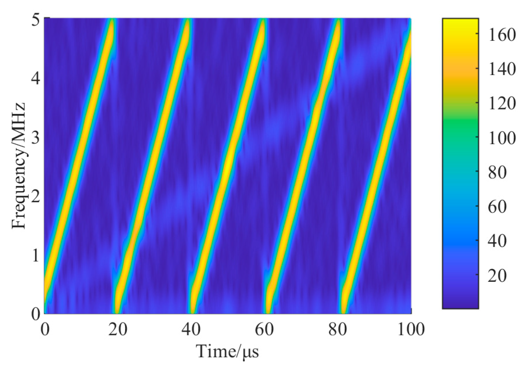
The time-frequency (TF) analysis of the mixed signal including the true target, SMSP interference, and noise by short-time Fourier transform is shown in
Figure 3. The parameters of the short-time Fourier transform are as follows: the window length equals 32 samples, the number of overlapping samples equals 1, and the length of FFT equals 256 samples.
The results show that the five highlighted oblique lines in the TF domain correspond to the five interference sub-waveforms, while the true target is not obvious. It can also be seen that the true target and the SMSP interference are completely coupled in the time domain and the frequency domain, and have some coupling points in the TF domain, which indicates that the true target is difficult to separate from the interference in the time domain, the frequency domain, and even in the TF domain.
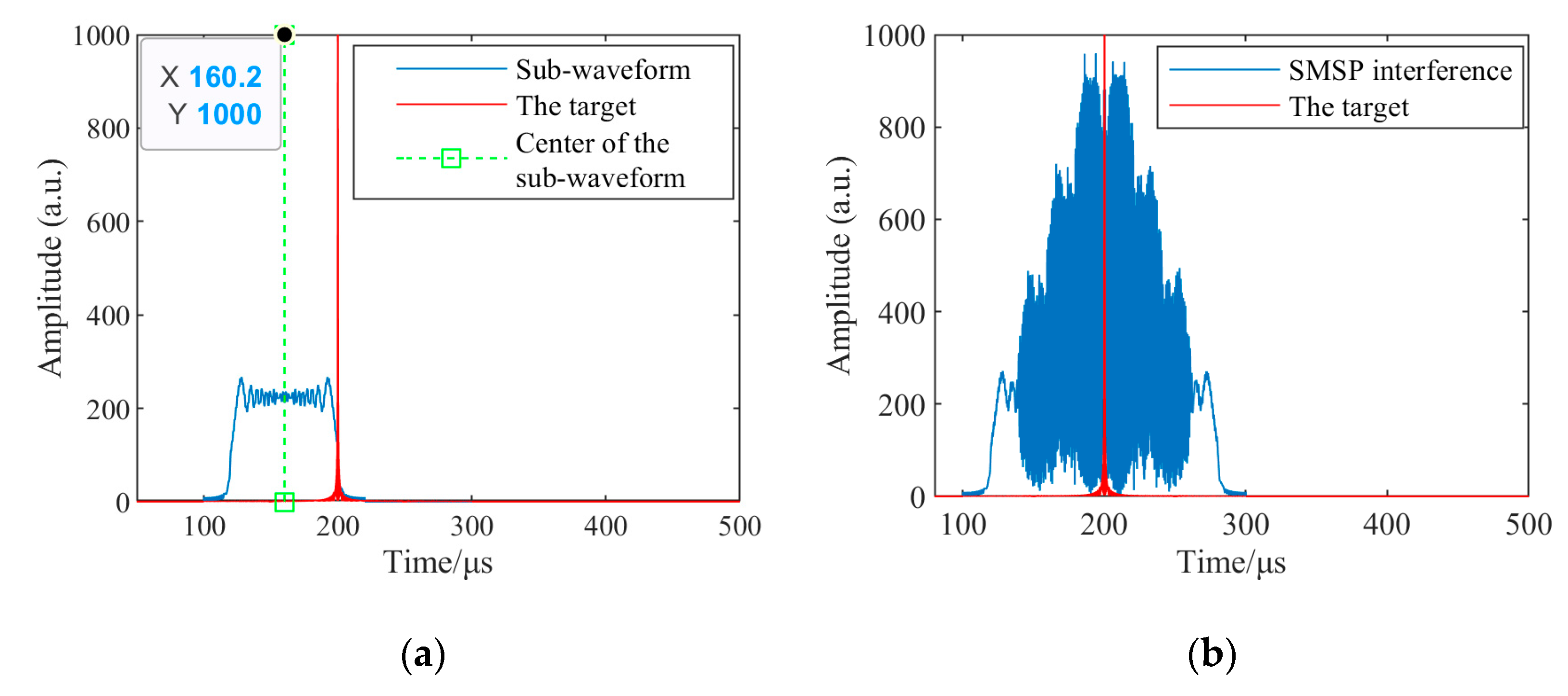
Figure 4a,b show the PC outputs of the first interference sub-waveform and the target as well as the PC outputs of the whole SMSP interference and target, respectively, when JSR equals 20 dB and SNR equals 0 dB.
In
Figure 4a, the envelope of the SMSP sub-waveform after PC is approximately rectangular, and the amplitude of the interference is much lower than that of the true target despite that
, which is caused by the mismatch between the SMSP interference and the receiver matching signal. In addition, the time delay of the true target is 200 μs, and the time interval between the sub-waveform center and the true target is 39.8 μs. The result is close to the theoretical value of 40 μs calculated by substituting the parameter values of
Table 3 into
Table 2, which confirms the theoretical analysis in
Section 3.
Figure 4b shows that the PC output of the SMSP interference is generated by the superposition of the PC outputs of multiple sub-waveforms, and the SMSP interference produces a large number of dense false targets leading and lagging the true target, which causes both suppressive and deceptive effects on the victim radar.
5.2. Interference Suppression Flow
As mentioned in
Section 4, before the reference signals construction, the first step is to obtain the time delay of the echo pulses. For the detection of time delay, three different methods including the envelope difference method, the slow-time differential entropy method [
28], and the proposed slow-time RMS difference method are employed, and the obtained results are shown in
Figure 5.
Figure 5a shows the unprocessed echo pulses in a CPI, where the interfered echoes are exceedingly obvious compared with the noise.
Figure 5b shows that the envelope difference method cannot obtain the time delay of the echo pulses completely when
. The noise has a significant impact on the detection results.
Figure 5c shows that the slow-time differential entropy method can detect the echo time delay correctly. However, there are some large sidelobes around the peak and these may affect the robustness of the time delay detection. This may be due to low SNRs or the fact that the distribution of the signal envelope of the interfered echo segment at slow-time does not match well with the Rice distribution when the samples are small. In contrast, the amplitude of the sidelobes around the peak in
Figure 5d is much lower than that in
Figure 5c, which indicates that the proposed RMS difference method is superior in terms of noise immunity and robustness.
The FM slope range
Q is set to
. According to the detected time delay
,
M different FM slopes are randomly selected from
to construct
M reference signals to modulate the echo pulses. Then, taking the preprocessed echo pulses and preprocessed radar-transmitted signals into matched filtering, the obtained results in comparison with the results without echo preprocessing are shown in
Figure 6.
Figure 6a shows that the true target is masked by a wide range of dense false targets formed by SMSP interference. On the other hand, the preprocessed true target become more visible in
Figure 6b. In addition, the preprocessed SMSP interference forms a range shifting including sub-waveform center shifting and range scaling in the distance dimension, which results in a reduction in the interference amplitude.
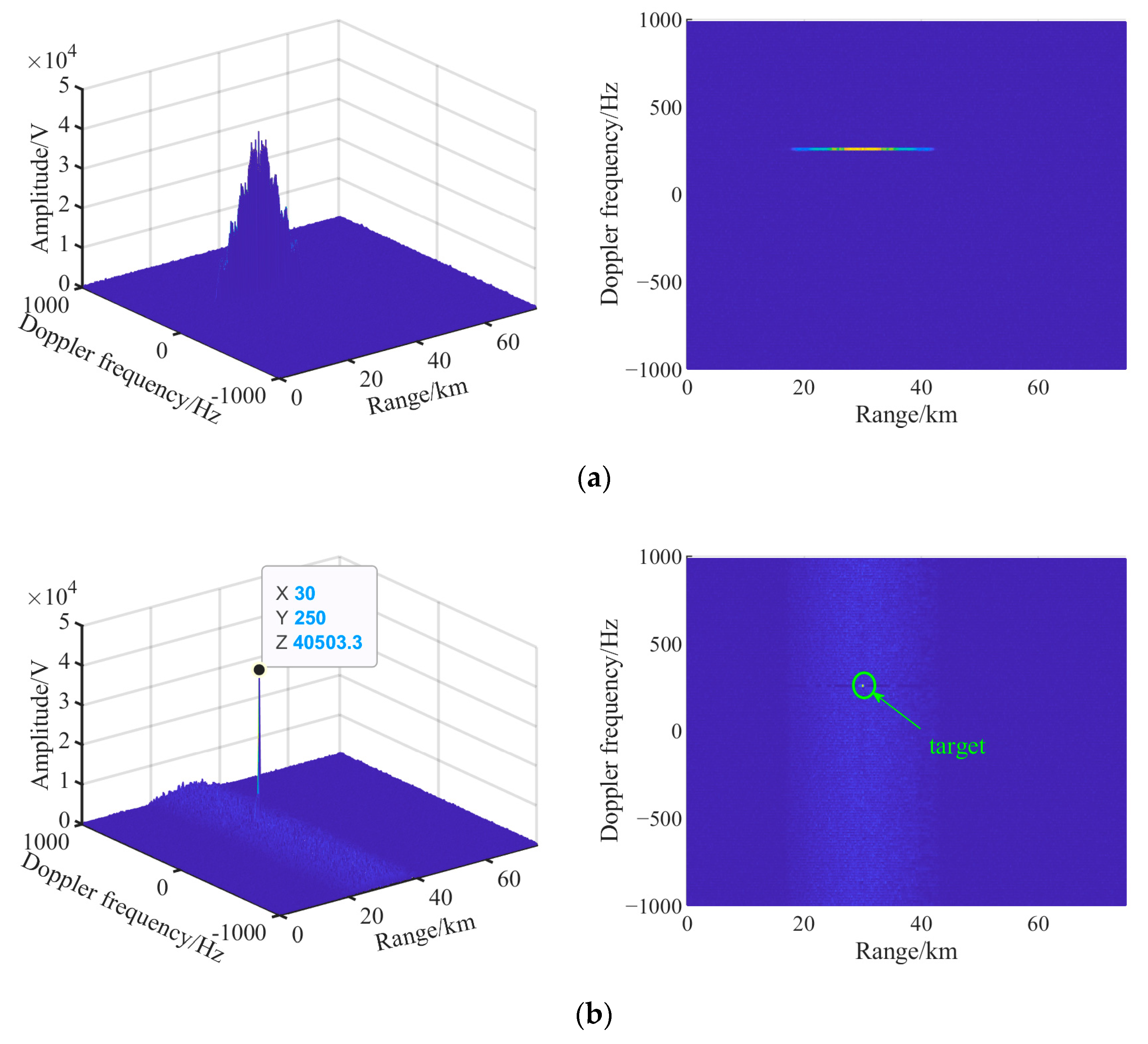
The range-Doppler (R-D) diagrams of the echo pulses obtained by the PC and CI before and after echo preprocessing are shown in
Figure 7.
Figure 7a shows that the SMSP interference obtains the CI gain and obscures the target in the R-D domain. Subsequently, the target cannot be detected and the corresponding distance and Doppler information cannot be obtained. In
Figure 7b, since the output of the SMSP interference after the PC is related to the slow-time according to (26), the interference cannot further obtain CI gain. Moreover, the range and Doppler frequency of the target are shown as 30 km and 250 Hz, respectively, which are consistent with the parameter settings.
Figure 7a,b indicate that the preprocessing method can effectively suppress the SMSP interference and extract the parameter information of the true target at the same time.
5.3. Algorithm Performance Analysis
5.3.1. Time Delay Detection Accuracy
To evaluate the detection accuracy of the echo time delay, the correct detection probability (CDP) [
29] is defined as
where the unit of CDP is percentage. MCN represents the number of Monte Carlo experiments.
represents the accurate measurement of the parameter in the
ith experiment. When the estimated pulse delay is consistent with the true value, the value of
is 1. Otherwise, the value is 0.
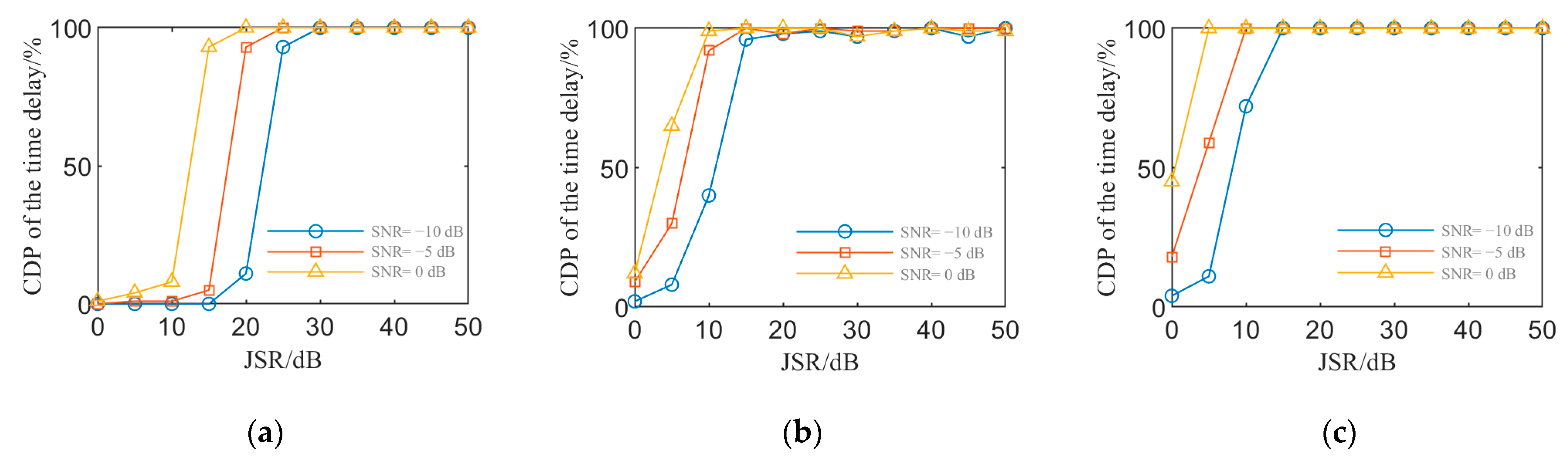
Figure 8 shows the curves of CDP of the time delay versus the JSR, which are obtained from 300 Monte Carlo experiments on different SNRs and three different detection methods, including the envelope difference method, the slow-time differential entropy method [
28], and the proposed RMS difference method.
In
Figure 8, the CDP values of the three methods increase with the increases in the SNR and JSR. Taking the CDP of the time delay being equal to 100% as the criterion for different methods to detect effectively, the results are summarized in
Table 4.
Table 4 shows that the lowest JSR requirement of the proposed method is 15 dB lower than that of the envelope difference method at different SNRs and is also lower than that of the differential entropy method, which reflects that the proposed method is preferable at lower JSRs.
Figure 8b shows the CDP of the differential entropy method is not always 100% at higher JSRs. Compared with
Figure 8c, the proposed method is more robust.
5.3.2. Target Detection Probability
The target detection probability (TDP) [
27] is defined as an index to evaluate the performance of the interference suppression method, i.e.,
where
represents the accurate detection of the true target via peak search in the
ith experiment.
equals 1 when the target is detected. Otherwise, the value is 0.
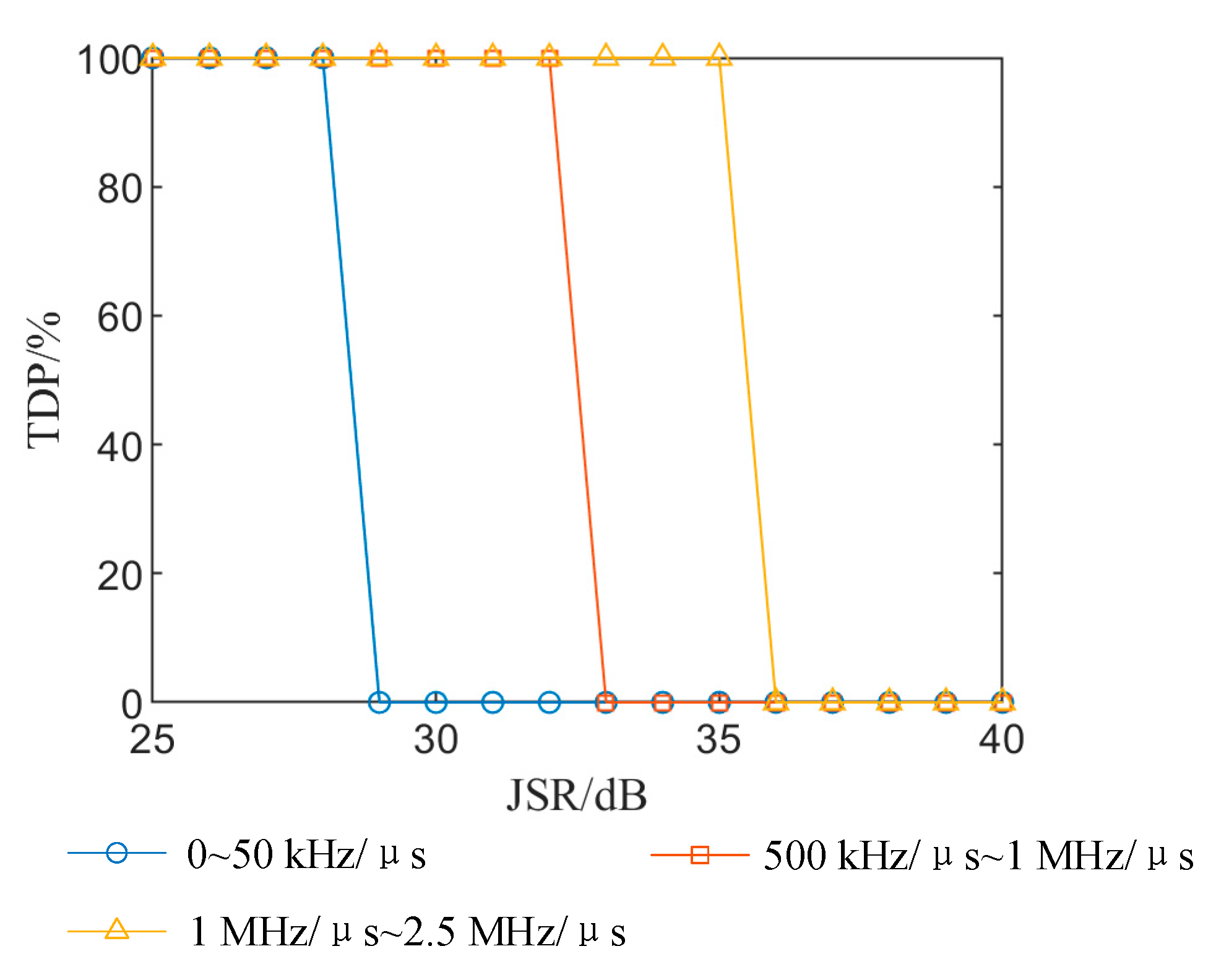
The FM slope range
Q is set to 1 MHz/μs~2.5 MHz/μs. The TDP curves of different suppression methods versus JSR and SNR calculated by 300 Monte Carlo experiments are plotted in
Figure 9.
Figure 9a shows that the TDP without interference suppression is zero when the JSR is greater than 20 dB, which indicates that JSRs greater than 20 dB are generally required if the SMSP interference needs to suppress the target and affect radar detection effectively.
Figure 9b shows that the TDP of the LCT domain filtering method [
15] deteriorates after interference suppression because the interference has completely covered the target in the LCT domain when the JSR is greater than 20 dB so that the peak coordinate of the target cannot be accurately located. Moreover, there is still a large amount of residual interference after filtering, which seriously affects the detection of the target.
Compared with
Figure 9b, the TDP of the fractional domain signal reconstruction method [
22] is significantly improved in
Figure 9c. The TDP at different SNRs gradually decreases from 100% when the JSR is greater than 30 dB. This is because the error of reconstruction increases as the JSR increases.
Figure 9d shows the TDP curves of the blind source separation method [
24] when the angle between the interference and target equals
. It can be seen that the TDP cannot reach 100% at different SNRs and JSRs, which is because the angle between the target and jammer in the main lobe interference environment has a great impact on the performance of blind source separation.
In contrast,
Figure 9e shows that the critical condition of the proposed method for TDP dropping from 100% is 35 dB, which is 17.5 dB and 5 dB higher than that of the LCT domain filtering method and fractional domain signal construction method, respectively. In addition, the proposed method has better noise immunity compared with the blind source separation method and fractional domain signal reconstruction method.
5.3.3. Target Energy Loss
The main step of the proposed method is echo preprocessing, namely, modulating the echo pulses by reference signals. Equations (10) and (23) show that the peak amplitude of the target remains unchanged before and after echo preprocessing when the reference time equals the time delay, which means the peak power of the target will not be lost after interference suppression. However, the LCT is the generalization of the fractional Fourier transform, and the fractional domain is the intermediate domain between time and frequency, where the interference is partially coupled with the target. Therefore, the LCT domain filtering and fractional domain interference reconstruction will lose some peak power of the target. Moreover, SMSP interference, as an SPDI, is a main lobe interference. The separation performance will deteriorate, and the target energy loss will be great when the angle between the target and the jammer is very small. In summary, the proposed method is preferable in terms of target energy loss.
5.4. Effect of Parameters on Algorithm Performance
5.4.1. Coherent Integration Number M
The curves of TDP versus JSR at different coherent integration numbers, calculated by 300 Monte Carlo experiments, are plotted in
Figure 10.
Figure 10 shows that the TDP increases with the increase in coherent integration number but this improvement is not obvious. This is because the interference amplitude is superimposed by multiple sub-waveform amplitudes. The large distance sidelobes near the target are difficult to suppress when the JSR is too large. The coherent integration number
M selected as 64 is appropriate.
5.4.2. FM Slope Range Q of the Reference Signals
To further investigate the effect of the FM slope range, the FM slope range
Q is set to 0~
k,
k~10
k, 10
k~20
k, and 20
k~50
k. The PC results of the preprocessed echo pulses in a CPI are shown in
Figure 11, when
and
.
Figure 11 indicates that the preprocessed interference is more distributed in the distance dimension after PC, and the energy of the interference near the true target is significantly reduced when
increases from kHz/μs to MHz/μs and the range
Q expands simultaneously.
The value of SNR remains unchanged. The curves of the TDP versus JSR at different FM slope ranges, calculated by 300 Monte Carlo experiments, are given in
Figure 12.
Figure 12 shows that the critical condition for TDP dropping from 100% becomes loose when the values of
increase to MHz/μs and the FM slope range
Q of
expands. In summary, we can achieve better interference suppression performance when the values of
km reach MHz/μs and the FM slope range is expanded at the same time.
6. Conclusions
In this paper, a novel SMSP interference suppression method based on echo preprocessing is proposed in the context of PD radar anti-self-protection interference. The method includes time delay detection, reference signals construction, echo preprocessing, and PC and CI. Doppler information is also considered in our model, and we can finally obtain the distance and Doppler frequency of the true target after interference suppression. Based on the interference suppression process and experiments, the proposed method has the following advantages:
- (1)
The proposed method does not need to convert the signal to the transform domain for processing, but only to carry out reference signal modulation on the echo pulses and radar-transmitted signal, which is easily embedded in the process of radar signal processing in PD radar and can be applied to existing radar systems.
- (2)
The proposed slow-time RMS difference method has better noise immunity and robustness to detect the time delay of the echo pulses compared with the envelope difference method and slow-time differential entropy method.
- (3)
The proposed interference suppression method does not involve filtering, reconstructing the signal or signal separation during signal processing, so the energy of the target signal is not lost. In addition, when the SNR is greater than −10 dB and the JSR is less than 35 dB, the TDP after interference suppression by peak search can reach 100%, which outperforms the three typical representative methods in terms of JSR tolerance.
- (4)
The effects of the parameters on interference suppression are discussed. The proposed method is not sensitive to CI number, while large values of such as MHz/μs, and a wide FM slope range expanded to MHz can improve the performance of interference suppression.
Nevertheless, the real electronic countermeasure environments may be more complex than the considered environment. Multiple adjacent targets may affect the detection of the time delay. In addition, the key of the proposed method is to couple the output of the interference with slow-time by echo preprocessing such that the SMSP interference cannot obtain CI gain. However, the CI gain is limited for the true target, and the true target can still be obscured by false targets at ultra-high JSRs. Hence, the ultra-high-power background and more complex electronic countermeasure environments should be considered in our future works.


