Abstract
At present, the hydraulic support pushing system in coal mines usually uses an electrohydraulic directional valve as the control component. However, the existing control methods based on high-speed on–off valve, servo, and proportional control methods are not suitable for solving such problems because of the nonideal characteristics of the electrohydraulic directional valve, such as discrete input values, low switching frequency, and time delay. This paper proposes a positioning control scheme based on online predictive feedback for the control of hydraulic cylinders by electrohydraulic directional valves. In this scheme, the recursive least-squares estimation algorithm with genetic factors is used to identify the required prediction model in real time, and an improved radial basis function network based on generalized growth and shear is used to realize the online fitting of the target trajectory function. The online learning algorithm provides accurate prediction information for the switching control method, and finally, the hydraulic cylinder can be positioned near the target position using the optimal control method. By using the above methods, a well-designed model can be accurately identified, fundamentally solving the problem of control difficulties caused by the nonideal characteristics of the electrohydraulic directional valve. Finally, the effectiveness of the control scheme is verified through simulation analysis and physical experiment research, which proves that the control strategy can realize accurate and fast positioning control for the hydraulic support pushing system of a fully mechanized mining face.
1. Introduction
Intelligent mining of coal mines is an effective way to achieve safe and efficient development of coal resources [1,2]. The continuous and stable collaborative operation of the comprehensive mining equipment group in the working face is the foundation of intelligent mining [3]. As one of the most important equipment in the comprehensive mining equipment group of the working face, the hydraulic support is mainly responsible for the relative position of the scraper conveyor and providing a safe working space for the working face. The straightness of the hydraulic support group directly affects the continuous coordination effect of the equipment automation in the fully mechanized mining face, thereby affecting the level of intelligent mining in the working face. Therefore, being able to achieve precise positioning control of the hydraulic support pushing system for fully mechanized mining faces under complex working conditions in coal mines [4,5,6] is the most fundamental and key technology for achieving intelligent mining in coal mines and has become a hot research topic at this stage. At present, the on–off-type electrohydraulic element of the hydraulic support of the fully mechanized coal face adopts an electrohydraulic directional control valve, which is suitable for high-pressure, large flow, and high water-based mining, has low cost and long service life. The positioning control method of the hydraulic cylinder pushing system is simple logic control, namely a built-in magnetic ring displacement sensor is arranged at an extension port of a piston of the pushing cylinder. The position of an oil cylinder piston is judged through a magnetic ring. When the control system receives a pushing signal from the hydraulic support, the electrohydraulic directional control valve is opened, and the emulsion with certain pressure enters the pushing oil cylinder to push a pushing rod to move forwards. When the control system receives the set target position signal, the directional valve is directly closed so that the hydraulic cylinder is stopped. However, due to the switch delay characteristic of the electrohydraulic directional control valve and the uncertainty involved in the control method, the final stop position of the hydraulic cylinder and the target position will have a large deviation. Overall, although the existing control methods have lower costs, their positioning accuracy is not high, and their moving efficiency is low, making them Unable to adapt to the current high yield and efficient development of coal mines. Therefore, it is a very valuable research subject to study the electrohydraulic directional control valve and its control method, and then realize the precise positioning control of the pushing cylinder, which will provide technical support for the high-yield and high-efficiency coal mine, intelligent and unmanned control of the working face.
In this research, the control element is an electrohydraulic directional control valve, and the executive element is the pushing cylinder. Through the switching control of the electrohydraulic directional control valve, the positive, negative, and zero-speed values of the pushing oil cylinder are realized and maintained, and finally, the pushing oil cylinder approaches the target position through the positive and negative speed values, and the pushing oil cylinder is maintained at the target position by changing the speed to zero. However, the design of the control is limited by the influence of many nonideal characteristics of the electrohydraulic directional control valve. Firstly, the input signal of the switching value of the electrohydraulic directional control valve is limited and discrete; secondly, the switching frequency of the control signal is relatively low; at last, there is a time delay characteristic between the control signal sending and the actual switching of the valve port under the large flow condition.
The above input limits make the positioning control of the hydraulic support pushing system based on the electrohydraulic directional control valve more difficult. The common positioning control system of the valve-controlled cylinder can be divided into high-speed switch valve, switch array control system [7,8,9], servo and proportional control system [10,11], electromagnetic directional valve, and electrohydraulic directional control valve control system according to the type of control element.
The existing high-speed on–off valve control usually adopts the pulse-width modulation (PWM)/pulse frequency modulation (PFM) control method [12,13,14,15] and the direct switching control method [16,17]. Van Varseveld et al. [9] studied position control based on PWM high-speed on–off valves. Through experimental duty cycle and steady-state speed open-loop steady-state mapping, precise position control was achieved using PID. Scheidl R [18] studied the basic characteristics of a PWM hydraulic pressure-regulating circuit by using an accumulator, a long oil pipe, and a one-way valve to form a pressure-regulating circuit. Liu Zhihao et al. [19] proposed a PWM-based PD control and a velocity feedforward displacement feedback composite algorithm and used genetic algorithms to tune control parameters. The control method based on high-speed on–off valves has high requirements for the cleanliness of the transmission medium, short service life, low reliability, and high manufacturing costs.
The servo and proportional control system realizes spool control through a mechanical–electrical closed loop composed of a spool displacement sensor, a closed-loop control circuit, and a proportional amplifier [20,21], and the opening of the control valve port is continuously adjustable. Cheng et al. [22] proposed a position control method based on feedforward compensation for direct-acting high-frequency response proportional valves to improve the frequency response and control performance of electrohydraulic proportional valves. Mao [23] designed static and dynamic compensation algorithms based on the nonlinear characteristics of proportional valve-controlled hydraulic cylinder systems and applied them to PID control algorithms, achieving good results. Wang et al. [24] established a corresponding mathematical model for the coal mining electrohydraulic proportional position system and combined a single neuron with PID to achieve good control results. At present, there is no mature industrial application example of electrohydraulic proportional valves for water media.
The above control method is not suitable for the electrohydraulic directional control valve with discrete control signal, time delay, and low switching frequency characteristics. At present, the control of the electromagnetic directional valve and the electrohydraulic directional control valve is usually completed in the form of a single opening/closing by means of a proximity switch or other sensors. In order to avoid the positioning error caused by time delay, it is often corrected by setting advance [25,26]. However, the existing control method has a good switching effect only under a single working condition, and the related control algorithm only provides the switching conditions at the final stop stage, so the applicability is poor. In addition, researchers have conducted in-depth research on switching control for existing switch control technologies. Ning et al. [27] solved the stochastic stability and control synthesis problem of discrete semi-Markov jump systems with upper bound dwell time using the semi-Markov kernel method. Nie et al. [28] adopted a new finite-time switched linear variable parameter control method to ensure the finite-time H ∞/LQR performance of the error tracking system of a quadcopter. Yang et al. [29] studied the control synthesis problem of a class of discrete semi-Markov jump linear systems and applied it to the flight positioning control process.
In summary, due to the discrete input values, low switching frequency, and time delay of the electrohydraulic directional valve, the existing control methods based on the electrohydraulic directional valve cannot meet the positioning control of the hydraulic support pushing system under complex working conditions in coal mining. Therefore, it is particularly important to propose a more advanced and effective control scheme to solve the problem of poor applicability of current positioning control methods based on electrohydraulic directional valves and low overall performance of hydraulic support propulsion systems.
In response to the problems of discrete output values, low switching frequency, and time delay in the control process of electrohydraulic directional valves, predictive feedback control methods are commonly used for positioning control. The basic control idea is to issue commands at the advanced level through statistical or predictive switching advance, in order to achieve precise positioning control. However, in the actual positioning process, it often occurs that when the target position is close to the current position, it cannot be guaranteed that the system will reach the switching conditions, which may lead to the system repeatedly switching near the target position and instability. In addition, under variable operating conditions, the method of directly calculating the lead time is not available. A positioning control scheme based on online predictive feedback is proposed to address the above issues. This scheme constructs an advanced model in real time through learning algorithms, enabling real-time switching commands to be issued in advance, thereby achieving real-time and accurate positioning control. In addition, the switching conditions and switching control methods have been supplemented to ensure that the system can achieve the switching conditions. Specifically, based on accurate prediction of future states, this scheme utilizes advanced switching control methods that can switch under zero switching conditions, resulting in the system eventually converging to zero. For the positioning control of electrohydraulic directional control valves, control input constraints, delay characteristics, and control problems caused by system nonlinearity and uncertainty are mainly solved through online identification of some good models, while good prediction models are identified through corresponding learning algorithms: the prediction model of future states is identified through recursive least-squares method based on forgetting factor; Identify the required target trajectory function model through an improved generalized growing and pruning radial basis function network (improved GGAP-RBF) algorithm. Compared with traditional RBF networks and GGAP-RBF [30,31,32,33,34], the improved GGAP-RBF dynamically adjusts the minimum allowable center distance between network nodes and adjusts the overlap factor through adaptive methods, thereby achieving adaptive adjustment of the radial basis function width of hidden layer neurons. Ultimately, the adjustable parameters of the algorithm are further reduced, the network structure is simplified, and the generalization ability of the algorithm is improved. In summary, the proposed positioning control method based on online predictive feedback can continuously optimize the positioning control results of the hydraulic support pushing system in coal mines, thereby improving the straightness of the entire working face. Finally, on the premise of meeting the positioning requirements of the hydraulic support pushing system in the fully mechanized mining face, in order to improve the pushing efficiency, a simplified design of the controller was carried out, and the effectiveness of the scheme was verified through simulation and experiments.
2. Materials and Methods
This research takes positioning control as the goal. It does not require the position, the velocity continuous tracking control, and the velocity in the arbitrary value; therefore, it only requests that the velocity sign maintains the positive and the negative, and it has no explicit request to the concrete numerical value. The current system makes the hydraulic cylinder realize and maintain positive, negative, and zero position change rates (i.e., speed value) through three control input values of the electrohydraulic directional control valve. The target position is approached by the positive and negative speeds, and the target position is maintained by making the speed zero.
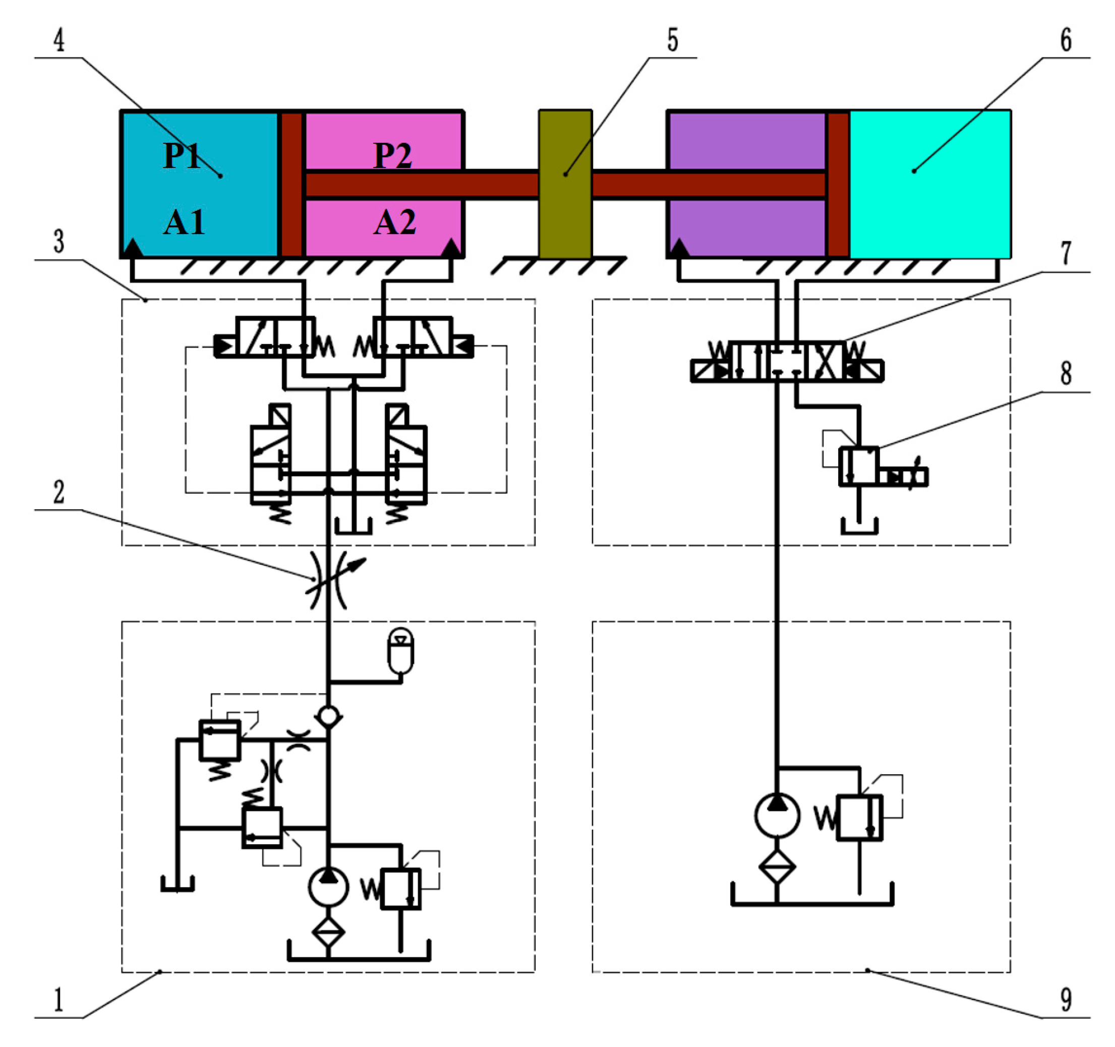
The hydraulic schematic diagram of the system is shown in Figure 1. The system consists of the pushing system and the loading system. The pushing system takes a single-rod hydraulic cylinder as the control object. The hydraulic cylinder is fixed horizontally, the speed adjustment and positioning control are realized by the throttle valve and the Y-type electrohydraulic directional control valve, and the oil source pressure is adjusted by the proportional relief. When the electrohydraulic directional control valve is opened to the left or right, the positive and negative movement of the hydraulic cylinder can always be ensured by reasonably setting the set pressure of the overflow valve and the output flow rate of the pump. When the electrohydraulic directional valve is in the middle position, it can achieve the final stop action of the hydraulic cylinder. In the loading system, the proportional relief valve at the loop end is adjusted to change the oil return back pressure of the loading cylinder so as to realize the adjustment of different load forces. Therefore, the control experimental system meets the basic requirements of the positioning control.
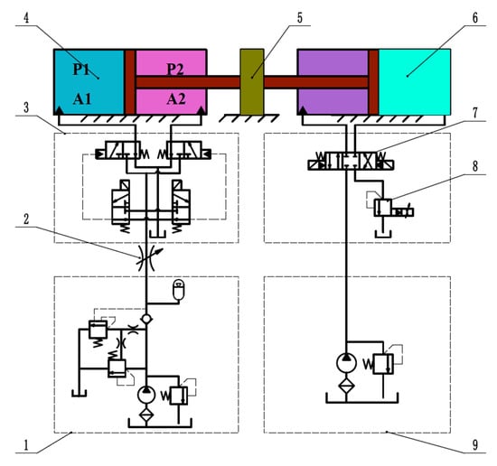
Figure 1.
System diagram of positioning control experiment. 1—emulsion pump station, 2—throttle valve, 3—electrohydraulic directional control valve, 4—advancing cylinder, 5—cylinder connection block, 6—loading cylinder, 7—solenoid directional valve, 8—proportional relief valve, 9—loading pump station.
2.1. Characteristic Analysis of Electrohydraulic Directional Control Valve
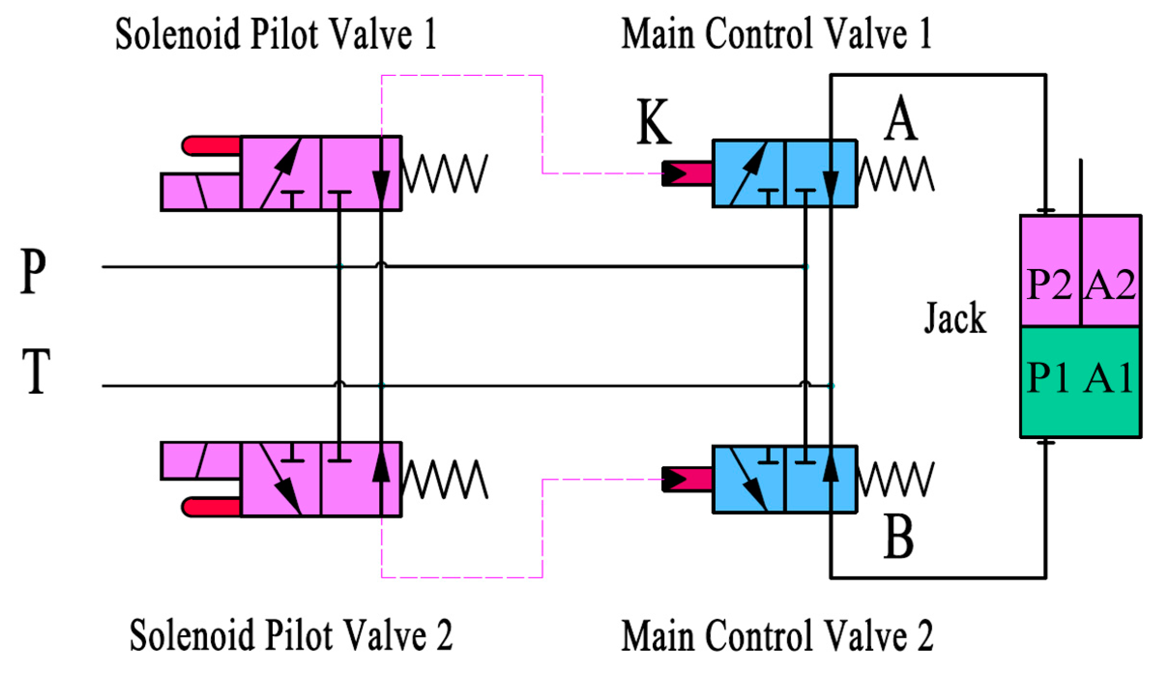
As the control component of the system, the characteristics of the electrohydraulic directional control valve are the main factors that affect the positioning control. Shown in Figure 2 is a hydraulic support electrohydraulic directional control valve of a basic circuit, where a solenoid pilot valve controls the main valve, and two groups constitute a circuit. Firstly, when solenoid pilot valve 1 is energized, it will open. At this time, the control oil flows through control port K to open main control valve 1, and the high-pressure emulsion at port P enters the upper chamber of the jack through main control valve 1. At the same time, the emulsion in the lower chamber returns to the oil return pipeline through main control valve 2, completing the cylinder retraction action. On the contrary, when solenoid pilot valve 2 is energized, the cylinder completes the cylinder extension action.

Figure 2.
The basic working circuit of electrohydraulic directional control valve.
The structure diagram of a single group is shown in Figure 3, and the valve is mainly composed of an electromagnet, a pilot valve, and a main valve. The working principle is as follows: when the electromagnet is electrified, the electromagnet pushes the left and right small balls of the pilot valve to move rightwards through the push rod. The small ball at the left end is tightly pressed on the valve seat, the liquid return port O of the pilot valve is closed, the small ball at the right end is opened, the working port of the pilot valve is opened, the high-pressure emulsion at port P reaches the control port K of the main valve and enters the control cavity of the main valve through the damping hole, the liquid return valve core of the main valve firstly executes action to close the oil return port O of the main valve, and the liquid inlet valve core is opened, and port P is communicated with port A to realize liquid supply. When the electromagnet is powered off, the pilot valve is reset under the action of the reset spring, and the pressure at port K of the main valve becomes zero. Under the action of hydraulic pressure and spring force, the liquid return valve core and the liquid inlet valve core are reset in sequence, and port P is closed to stop the liquid supply.
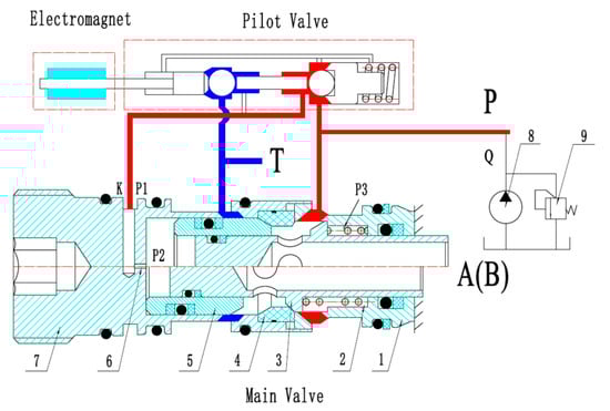
Figure 3.
Structure diagram of electrohydraulic directional control valve. 1—inlet valve sleeve, 2—main control valve spring, 3—inlet valve spool, 4—valve seat, 5—return valve spool, 6—fixed hydraulic orifice, 7—return valve sleeve, 8—pump, 9—relief valve.
The circuit of the whole electrohydraulic directional control valve is switched to three states through two electromagnets so that the input of the electrohydraulic directional control valve is a discrete value and can only be a positive-value input, a zero-value input, and a negative-value input, and three different hydraulic loop communication modes are correspondingly generated.
First, control signal U from the controller and the corresponding state of the electrohydraulic directional control valve are defined as follows:
① is a positive input command. Solenoid pilot valve 1 is electrified, and port A is connected with port P;
② is a zero input command. Solenoid pilot valves 1 and 2 lose power, and ports A, B, and P are connected;
③ is a negative input command. Solenoid pilot valve 2 is energized, and port B is connected to port P.
Secondly, there is a time delay between the control signal and the corresponding connection mode generated by the electrohydraulic directional control valve. When the electromagnet is powered on or off, the current will slowly rise or fall due to the inductance of the coil. According to Cetinkunt’s [35] modeling results, the electromagnetic force is related to the coil current. With the slow rise or fall of the current, the electromagnetic force will also rise or fall slowly. Only when the electromagnetic force is greater than a certain value, the valve core will be pushed to the correct position, which leads to a delay in switching. Therefore, the dynamic change of the electromagnetic force of the electromagnet and the friction caused by the imbalance of the radial force when the spool is closed cause the delay characteristics of the electrohydraulic directional control valve.
Finally, the stable switching frequency that the electrohydraulic directional control valve can achieve is relatively low. When the input frequency is too high, on the one hand, due to the existence of delay, it becomes unknown whether the input of each voltage switch can be responded to; on the other hand, the electrohydraulic directional control valve will become an unknown and uncontrollable link because it is impossible to judge the opening and closing of the current valve port directly by the relationship between the current input signal value and the delay.
Through experimental testing of the electrohydraulic directional control valve, combined with the accuracy requirements of the positioning control of the hydraulic support pushing system in the fully mechanized mining face, in order to facilitate the design of the controller, the control signal in this article is required to be below 2 Hz, which can ensure that the valve core position and coil current are in a steady state, and the valve’s switching characteristics remain unchanged under the same initial state and input voltage.
2.2. Characteristic Analysis of Pushing Cylinder
The pushing cylinder system of the hydraulic support is essentially a valve-controlled single-outlet cylinder system. In order to simplify the design process of the controller, only the inertia and friction load of the actuator are considered in this study. Due to the need to consider the pressure drop process after zero-value switching and the dynamic process after hydraulic driving force unloading in the identification of prediction models and online learning of target trajectory functions in subsequent research, the pressure characteristics and friction characteristics of the pushing cylinder chamber are analyzed.
According to Newton’s second law, the piston dynamic equation is:
In the formula, is the position of the piston; is the total mass of the piston and the load converted to the piston; and represent the pressure of the piston chamber and the rod chamber, respectively; and and represent the area of the piston chamber and the rod chamber, respectively. is the viscous damping coefficient of the piston and load, is the load spring stiffness, and is the external load force acting on the piston.
The friction force of the pushing cylinder is partly from the sealing friction inside the cylinder and partly from the external load friction. The frictional load can be considered as a nonlinear function that is only related to the piston velocity, and the total frictional load force on the cylinder is denoted by [36,37]. The pressure characteristics of the chamber of the pushing cylinder are analyzed as follows. For the chamber with relatively uniform pressure distribution, the dynamic model of the chamber pressure can be expressed as:
where is the oil modulus of elasticity, is the volume of the chamber, is the flow rate into the chamber, and is the flow rate out of the chamber.
When the electrohydraulic directional valve switches from a nonzero state to a zero state, the flow rate flowing out of the two chambers of the hydraulic cylinder can be expressed as:
In the formula, and , respectively, represent the flow into the piston chamber and rod chamber of the hydraulic cylinder; represents the flow coefficient of the orifice of the electrohydraulic directional control valve; and , respectively, represent the orifice area of the electrohydraulic directional control valve connected with the piston chamber and the rod chamber of the pushing cylinder; and , respectively, represent the pressure of the piston chamber and the rod chamber; is the density of the emulsion; and is the pressure of the tank. Here, it is assumed that the pressure of the tank is 0, so .
Considering the compressibility of the liquid, the pressure and flow dynamic equations of the two chambers of the pushing cylinder that were originally connected to the pressure source can be expressed as:
where and are the modulus of elasticity at pressures of and , respectively; and are the areas of the piston and rod chamber, respectively; and is the velocity of the piston.
From the above equation, it can be concluded that the dynamic characteristics of pressure are determined by and . When the electrohydraulic directional control valve is switched to the zero state, the pressure in both chambers will quickly and monotonically decrease to a small value, so the hydraulic driving force will be adjusted to zero in a short time.
When the electrohydraulic directional valve switches from the zero state to the nonzero state, the flow entering the two chambers of the hydraulic cylinder through the electrohydraulic directional control valve can be expressed as:
In the formula, is the source pressure, and is the orifice area of the throttle valve. At this time, the pressure flow dynamic equation of the two chambers of the pushing oil cylinder originally connected to the pressure source can be expressed as:
Since the influence of speed cannot be ignored when the electrohydraulic directional control valve switches from the zero state to the nonzero state, the dynamic characteristics of pressure are determined by and . In conclusion, the dynamic pressure and piston speed of the system are stable.
In order to facilitate the design of the controller, the following simplified treatment is made: when the state of the electrohydraulic directional control valve is , is 0; when the state is , is a positive constant; when the state is , is a negative constant.
3. Positioning Control Strategy
Aiming at the nonideal characteristics of the electrohydraulic directional control valve, a positioning control strategy based on online predictive feedback control is proposed. The basic control idea is to switch the lead time through statistics or prediction, and issue commands at the lead time to achieve precise positioning control. Due to control input constraints, system nonlinearity, uncertainty, and other problems, the following problems may exist:
Firstly, When the target position is close to the current position, the system cannot be guaranteed to reach the handover condition;
Secondly, The method of the direct statistical lead time is not applicable under changing operating conditions.
To solve the above problems, the lead time model is reconstructed by a learning algorithm, and the switching conditions and switching control methods are supplemented. In order to better describe the specific positioning control strategy, specific analysis was conducted on the system motion process after zero-value switching, recognition of predictive models, online learning of target trajectory functions, and switching control methods.
This scheme utilizes a recursive least-squares estimation algorithm with genetic factors to identify the required prediction model in real time, and uses an improved generalized growth shear radial basis function network to achieve online fitting of the target trajectory function. Through online learning algorithms, precise prediction information is continuously provided for switching control methods, and ultimately the hydraulic cylinder can be controlled to the target position in the optimal way.
3.1. Analysis of Zero Switching Dynamic Process
In this study, we describe the dynamic process of switching control commands from positive values to zero values. After zero-value switching, the dynamic process of the pushing cylinder positioning control system in the future can be divided into two stages:
The first stage describes the system process from the connection between port and port to the connection between port and port . It includes a delay stage from the generation of a control signal to the occurrence of switching and a pressure drop process from the occurrence of the switching to the rapid decline of the pressure of the chamber previously connected with port to zero. In the delay stage, since the valve port is still in the original stable state, the hydraulic cylinder will still maintain the original stable speed , the speed is unchanged in this process, and the displacement variation is the product of the stable speed and the elapsed time. The pressure drop process can be approximated by a linear function as:
where is the pressure in the chamber originally connected to port at , is the steady-state pressure in the chamber originally connected to port , and is the duration of the pressure drop.
The second stage is the dynamic process after the hydraulic driving force is unloaded after port is connected with port . At this time, the piston chamber of the hydraulic cylinder is sucked empty in a short time, the hydraulic driving force provided by the pressure of the piston chamber is zero, and the hydraulic cylinder stops after sliding for a period of time under the action of friction force.
3.2. Learning Algorithm
3.2.1. Prediction Model and Its Recognition Method
The positioning control strategy involved in this study is designed by analyzing the dynamic characteristics of the system in the phase plane, where z represents the position error, and , where r is the target position, and x is the current position. The prediction model needs to calculate the state increment and , corresponding to the future time after the zero-value switching occurs, based on the current state values and ; that is, the state increment after the end of the first stage is predicted based on the current state value, so the corresponding future state values and can be expressed as:
For the pressure drop stage, the pressure of the chamber originally connected with port is approximately 0, and the pressure change process of the chamber originally connected with port meets Formula (11). At this time, since is greater than Stribeck speed, all friction load forces on the hydraulic cylinder can be expressed as [38,39]:
where is the Coulomb friction, and b is the viscous damping coefficient. Since the pushing system satisfies Formula (1), combining (11) and (13), it can be concluded that:
Then, the velocity dynamics at this time can be expressed as:
Solving the first-order nonhomogeneous differential equation yields:
When , , substitute to find the constant C. Since , when , , we finally obtain:
Integrating (17) yields:
In summary, the state increment at can be expressed as:
According to the above analysis, the future state increment and are unknown functions related to and . We can represent the dynamic increment of the first phase after the zero switching occurs by an approximate linear model:
where and are parameter vectors, and is an eigenvector, where . Due to the positive and negative differences in friction and the return oil model coefficients, and are different in different speed directions. Therefore, the model parameters in the positive and negative directions are denoted by and , respectively. Due to the uncertainty of the model, it is difficult to obtain the function model directly by establishing the mathematical model. In order to obtain the generalized prediction model, the involved parameters and will be obtained through good algorithm learning based on a large number of measurement data. Since and are the state increments from zero-value switching to future time , it can be obtained that:
As , is the current displacement value, is the final displacement value of this switching, , , , and in Equations (22) and (23) can be obtained through experimental data collection, and finally the parameter vector of single switching can be obtained. Through continuous switching data collection, the optimal parameters can be obtained through online identification of the recursive least-square method with a forgetting factor, and then brought into (19) and (20) to obtain the real-time prediction model.
3.2.2. Target Trajectory Function Online Learning
The target track function is mainly used for fitting the dynamic process of the hydraulic cylinder positioning control system after zero-value switching in the second stage, then estimating the function by using the current speed observation value, and further performing accurate positioning control on the pushing hydraulic cylinder through a subsequent switching control method. In the second stage, since the hydraulic driving force is zero, the pushing cylinder slides and finally stops by all friction forces , so when the speed is the same, the derivative of the state trajectory has no difference, the shape of the target trajectory function is fixed, and the change of the state along the phase plane trajectory can be expressed as follows:
Because the parameters of the friction force of the pushing cylinder are unknown and the model is uncertain, the parametric structure form of cannot be obtained directly through the theoretical model, and the strong time-varying working condition of the hydraulic support pushing system can cause the continuous change of the target trajectory function . So, in order to quickly adapt to the change, the target trajectory function is obtained through an online learning method based on the variation of actual data. In this paper, an improved generalized growing and pruning radial basis function network (improved GGAP-RBF) is used to realize the online fitting of the objective function. Before the improved GGAP-RBF is used, the data used need to be collected, and the data are the position and velocity in the second stage process. Before training, the original data shall be preprocessed by normalization, so the data acquired by single switching can be expressed as:
In the above data, is the final position of a single zero switch, . In the target trajectory function fitted by the learning algorithm, the independent variable is and the dependent variable is .
The improved GGAP-RBF network is the same as the GGAP-RBF network [30,31,32,33,34], which only contains one hidden layer, and the hidden layer contains M hidden nodes. Gaussian function is used as the kernel function of the nodes, so its input and output function can be expressed as:
where is the weight coefficient, and and , respectively, represent the center and width of the kernel function of the jth node. The improved GGAP-RBF not only puts forward the importance index of hidden nodes and designs the growth and cutting strategy of hidden nodes, but also obtains the minimum allowable median distance between network nodes in the importance index by a dynamic adjustment method and adjusts the overlap factor by a self-adaptive method, thereby realizing the self-adaptive adjustment of the width of the radial basis function of the hidden layer neuron. Finally, the extended Kalman filter [40] (EKF) is used to adjust the parameters of the hidden nodes. The improved GGAP-RBF algorithm is as follows:
- (1)
- Output of calculation network:
- (2)
- Parameters required in the calculation of importance indicators:
- (3)
- Determine whether to add hidden layer neurons by growth criteria:
If the above formula is satisfied, a new hidden layer neuron enters the network, and the corresponding parameters are updated at the same time: , , . When the above formula is not satisfied, the hidden layer node parameter , which is closest to the current input in the network, will be updated by using the EKF method. The specific adjustment process is as follows:
Then, and are updated by the following formulas.
In the above formula, is the process noise covariance matrix in the Kalman filter model, is the prior estimation error based on the previous training results, is the observation noise covariance, is the parameter to be updated, , is the covariance matrix corresponding to , and is the prior covariance matrix of .
- (4)
- Determine whether to delete hidden layer neurons through the pruning criterion:
If the above expression is satisfied, the hidden layer neuron is deleted, and the dimension of EKF is reduced accordingly.
3.3. Switching Control Method
The switching control method for the electrohydraulic directional valve is to determine when the switching is performed, and the hydraulic cylinder can be stopped near the target position. In this paper, by analyzing the dynamic characteristics of position error and velocity in the phase plane, the switching control method is designed. According to the analysis of the dynamic process of the hydraulic cylinder positioning control system in the two stages in the future after zero-value switching, it is known that:
At the end of the first stage, the future state values and can be expressed in the form of Equation (12), and at the end of the second stage, the state of the target trajectory function along the phase plane trajectory can be expressed in the form of Equation (24). At the end of the first stage, the system state can always satisfy the trajectory function given in (24), so when and satisfy:
Then, the system state can finally converge to zero when switching to zero in the current state and . In the above equation, and refer to the state prediction value at after the zero-value switching occurs. The above equation is called the zero-value switching condition.
According to the above analysis, in order to achieve the zero switching condition, it is necessary to control the system state to a point that meets the above equation. To facilitate the analysis, the distance from a certain state point to the target track is defined as:
Take the derivative of the above equation to obtain:
According to the analysis of the above formula, when the control command is , after the time delay is over, the emulsion enters the piston chamber of the hydraulic cylinder, and the pressure is greater than zero, at which increases. When the control command is , after the delay is over, the emulsion enters the rod chamber of the hydraulic cylinder, and the pressure is greater than zero. At this time, decreases. Therefore, the switching control law under any switching conditions can be obtained as follows:
In the above formula:
4. Simulation Analysis
In order to verify the effectiveness of the control strategy, a control theory model is established based on the description of the physical composition and working principle of the system in Figure 1.
4.1. Establishment of Simulation Models
This article takes the ZY3200/08/18D-type shield hydraulic support in thin coal seams as an example to study the forward installation push oil cylinder. In the forward installation structure, the pushing oil cylinder extends to push the scraper conveyor and retracts to pull the hydraulic support. The main parameters of the hydraulic support used in the simulation are shown in Table 1.

Table 1.
Main parameters of ZY3200/08/18D hydraulic support.
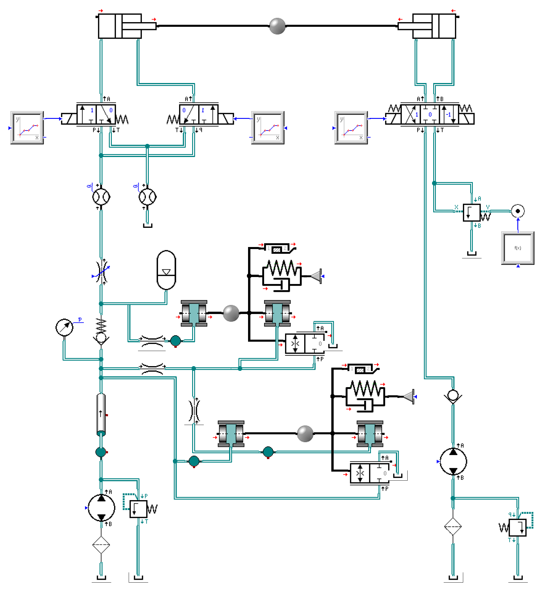
This article takes a group of push oil cylinders as an example and builds a physical simulation model of the experimental system in SimulationX, as shown in Figure 4. The push oil circuit uses an emulsion pump station as the power source, and the speed is adjusted through a throttle valve. The hydraulic oil flow direction in the push system is controlled through a Y-shaped electrohydraulic directional valve. The hydraulic oil pump is used as the power source in the loading oil circuit, and different loads are adjusted through a proportional overflow valve. The parameters involved are shown in Table 2.
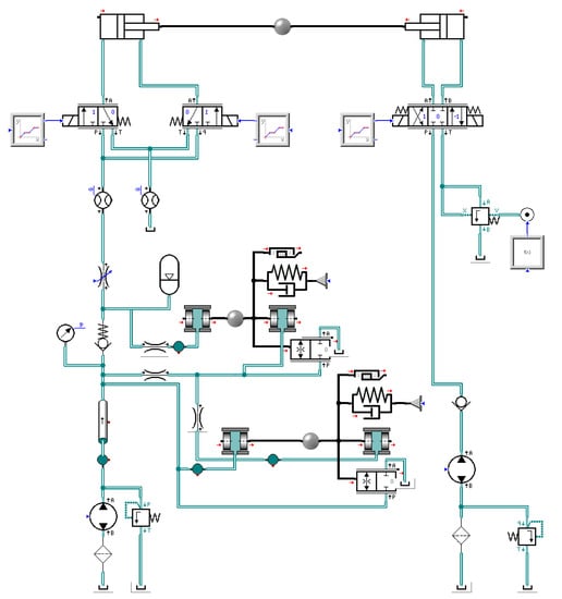
Figure 4.
A physical simulation model based on SimulationX.
Table 2.
Main parameters of physical simulation model.
At the same time, the positioning control strategy program of the hydraulic support pushing system of the fully mechanized coal mining face with the electrohydraulic directional control valve as the main control component is compiled through the S-function in MATLAB/Simulink. The key parameters required for the constructed controller model are shown in Table 3.
Table 3.
Key parameters of controller model (control algorithm).
Finally, the cosimulation platform is built by SimulationX and MATLAB/Simulink. The position, pressure, and velocity signals used in Simulink come from the physical simulation model in SimulationX, and the control voltage of the physical model in SimulationX needs to be calculated in Simulink through the compiled control program. Figure 5 shows the joint simulation model, The content in the red box has its switching control method, The content in the blue box has its SimulationX block.
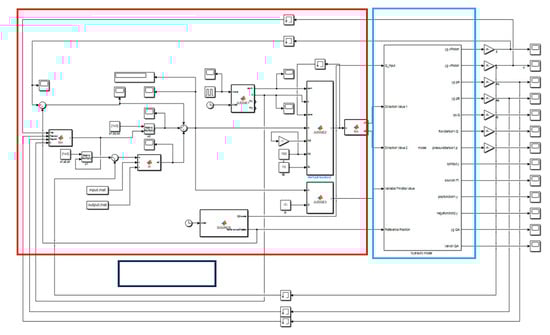
Figure 5.
Cosimulation diagram of positioning control of hydraulic support pushing system.
4.2. Simulation Results and Analysis
In the simulation experiment, tests were conducted on the positioning effect of fixed target positions under different steady-state speeds. The effectiveness of the simplified control algorithm including the predictive control model and the online curve fitting algorithm is verified by the analysis of the target signal positioning control results.
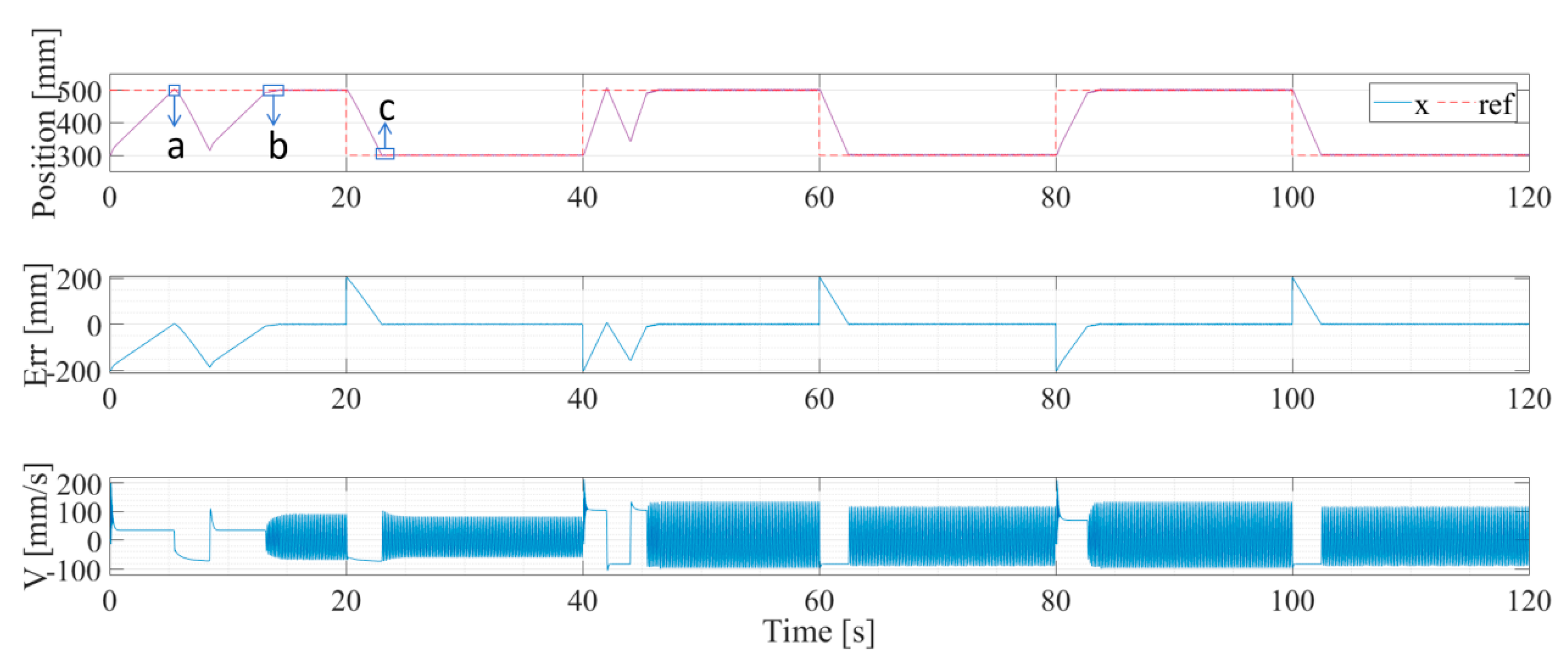
Figure 6 shows a positioning control state of a fixed target position. The target position is 0.05 Hz square-wave signal, and the stable values of the square wave are 300 mm and 500 mm, respectively.
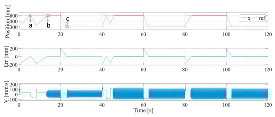
Figure 6.
Fixed target position control curve.
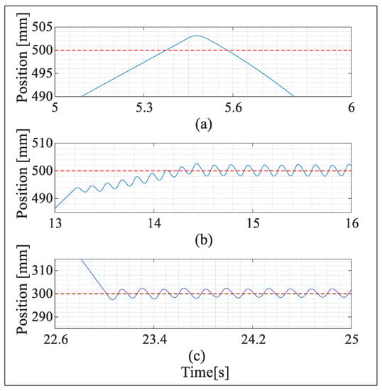
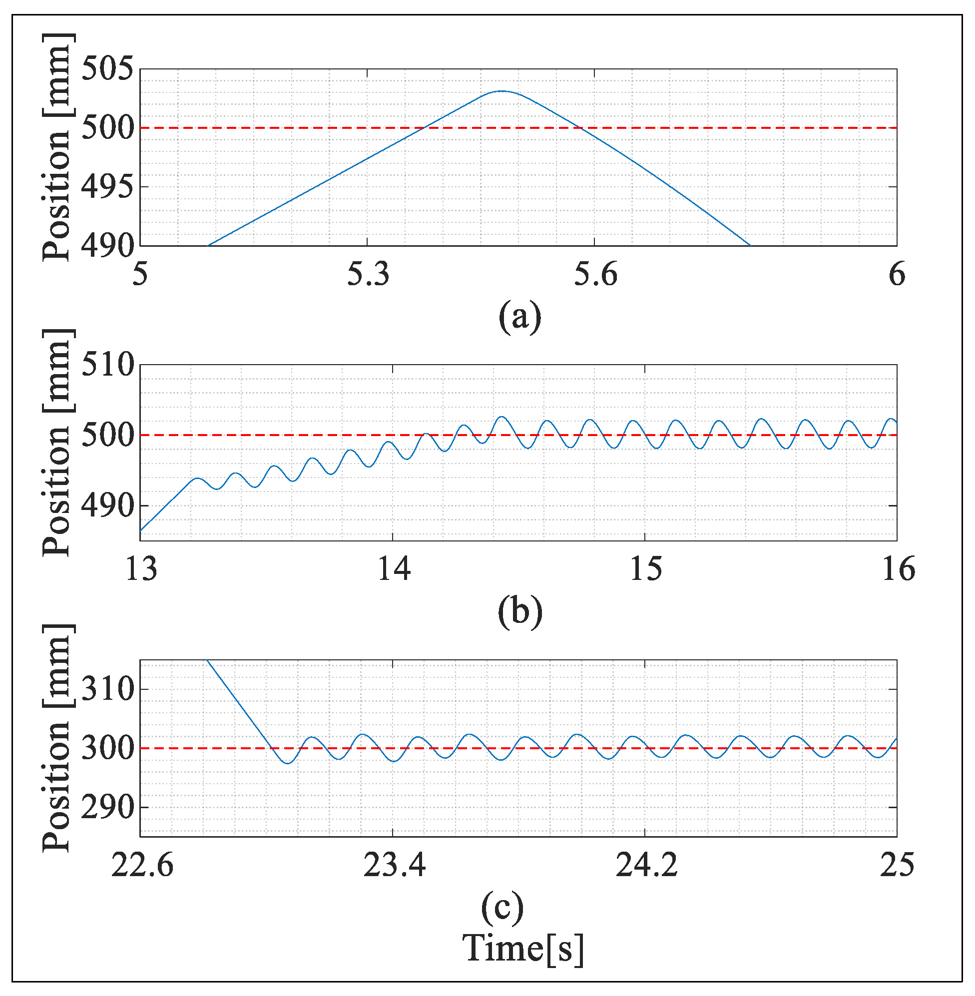
Figure 7 shows the local enlarged image corresponding to the positions “a”, “b”, and “c” in Figure 6. As can be seen from the figure, in the initial stage, the process of peak and trough first appears, which is due to the lack of observation data and because the prediction model has not been identified. Then, the wave-by-wave rising process occurs, because the instability of velocity and pressure in the zero-value switching process causes the accuracy of the linear prediction model and identified target trajectory function to be insufficient; thus, the adjustment process occurs; Finally, from t1 (14.5 s), the stable fluctuation can be achieved near the target position, because after the initial positive and negative zero-value switching process, the learning algorithm obtains better identification results through the training of observation data and finally realizes the positioning control of stable fluctuation.
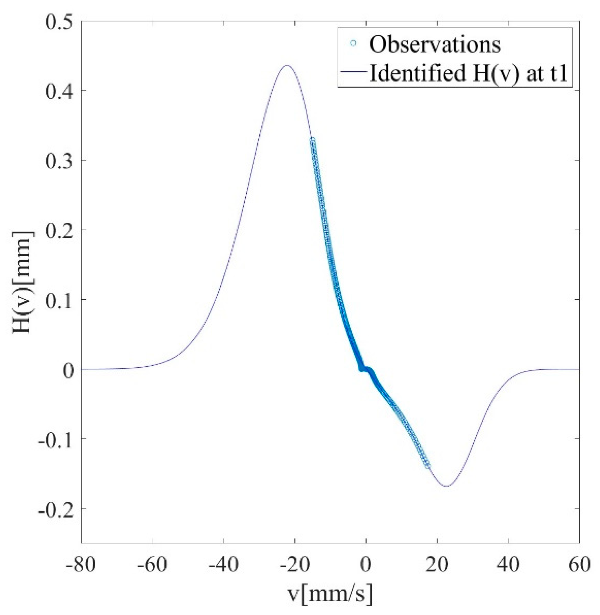
As shown in Figure 8, the target trajectory fitting result at t1 (41.5 s) shows that the improved GGAP-RBF can better fit the obtained observation data.
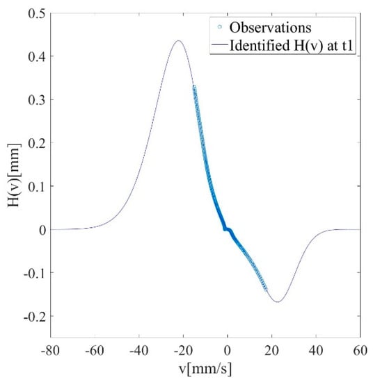
Figure 8.
Target track observation data at t1 in simulation and improved GGAP-RBF target track fitting results.
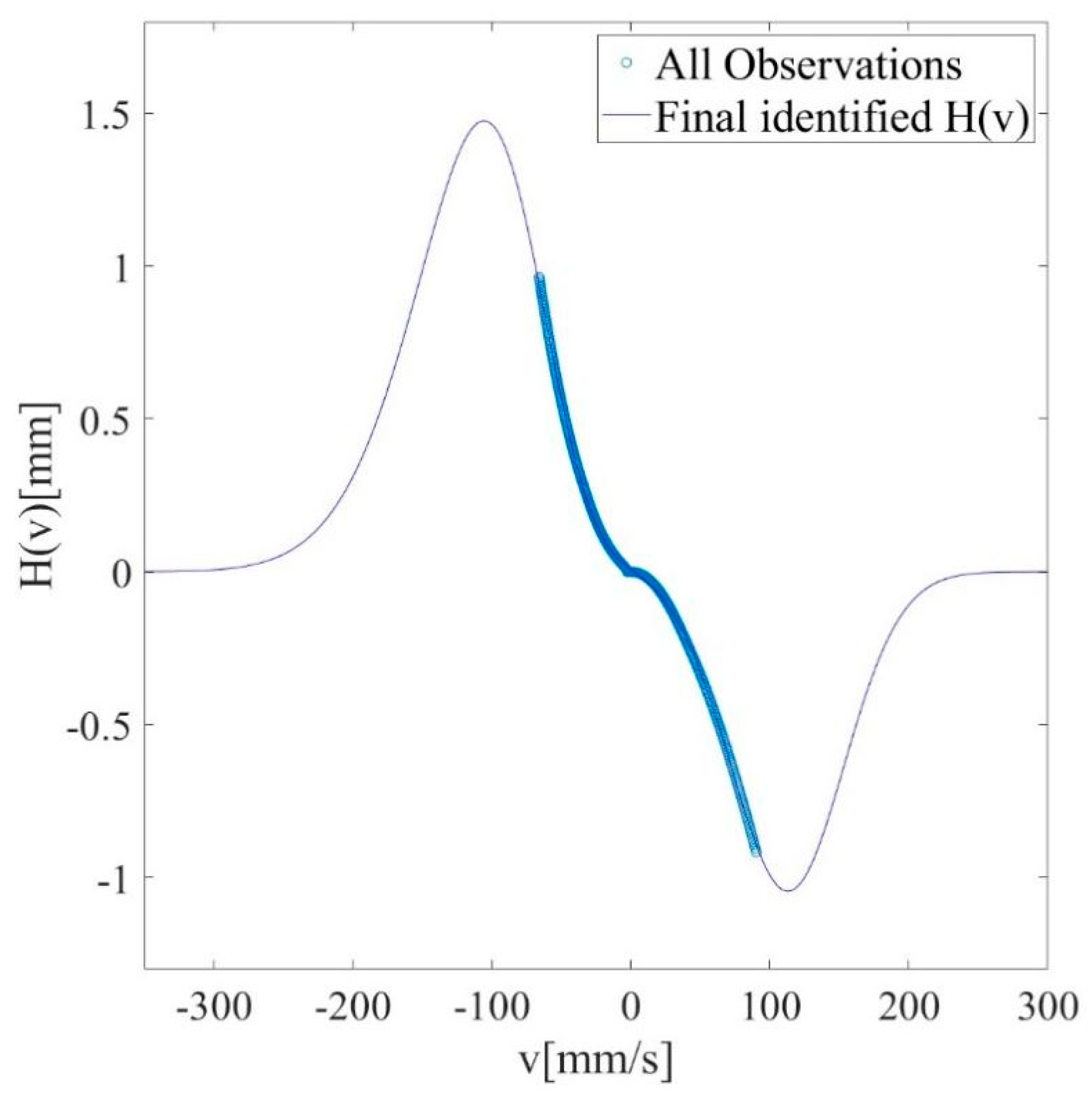
At t2 (40 s), the steady-state speed of the hydraulic cylinder is adjusted to a larger input value, and in this process, since the target trajectory is not observed within this speed range, a larger fluctuation begins to appear. With the increase in observation data, the learning algorithm obtains better identification results through the training of observation data and finally realizes the stable fluctuation positioning control at t3 (46 s). Figure 9 shows the target trajectory fitting result at t3 (46 s), which shows that the improved GGAP-RBF can quickly adjust the network parameters with the newly obtained observation data and better fit all the obtained observation data.
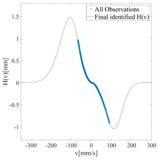
Figure 9.
Target track observation data at t3 in simulation and improved GGAP-RBF target track fitting results.
At t4 (80 s), the steady-state speed is adjusted again, but since the prediction model is well modified and the target trajectory is well fitted at this moment, the positioning control state is always in stable fluctuation. Through the above simulation results, we can find that in the initial process, there is a ramp-up wave stage, which is caused by the continuous change of caused by the continuous change of pressure and speed during the switching process of the electrohydraulic directional control valve, and the stable fluctuation near the target position is caused by the switching delay characteristic of the electrohydraulic directional control valve.
Through the above simulation analysis, the improved GGAP-RBF can quickly perform online data fitting and provide accurate and stable prediction results, the simplified linear model can effectively predict the state, and the proposed control algorithm based on online predictive feedback can meet the requirements of positioning control of the moving system.
5. Experimental Study
In order to verify the simulation results, and further verify the effectiveness of the designed controller, considering the actual performance of the positioning control of the hydraulic support pushing system in the fully mechanized coal mining face, according to the principle of similarity, the positioning control experimental platform of the pushing control system is built under laboratory conditions.
5.1. Experiment Configuration
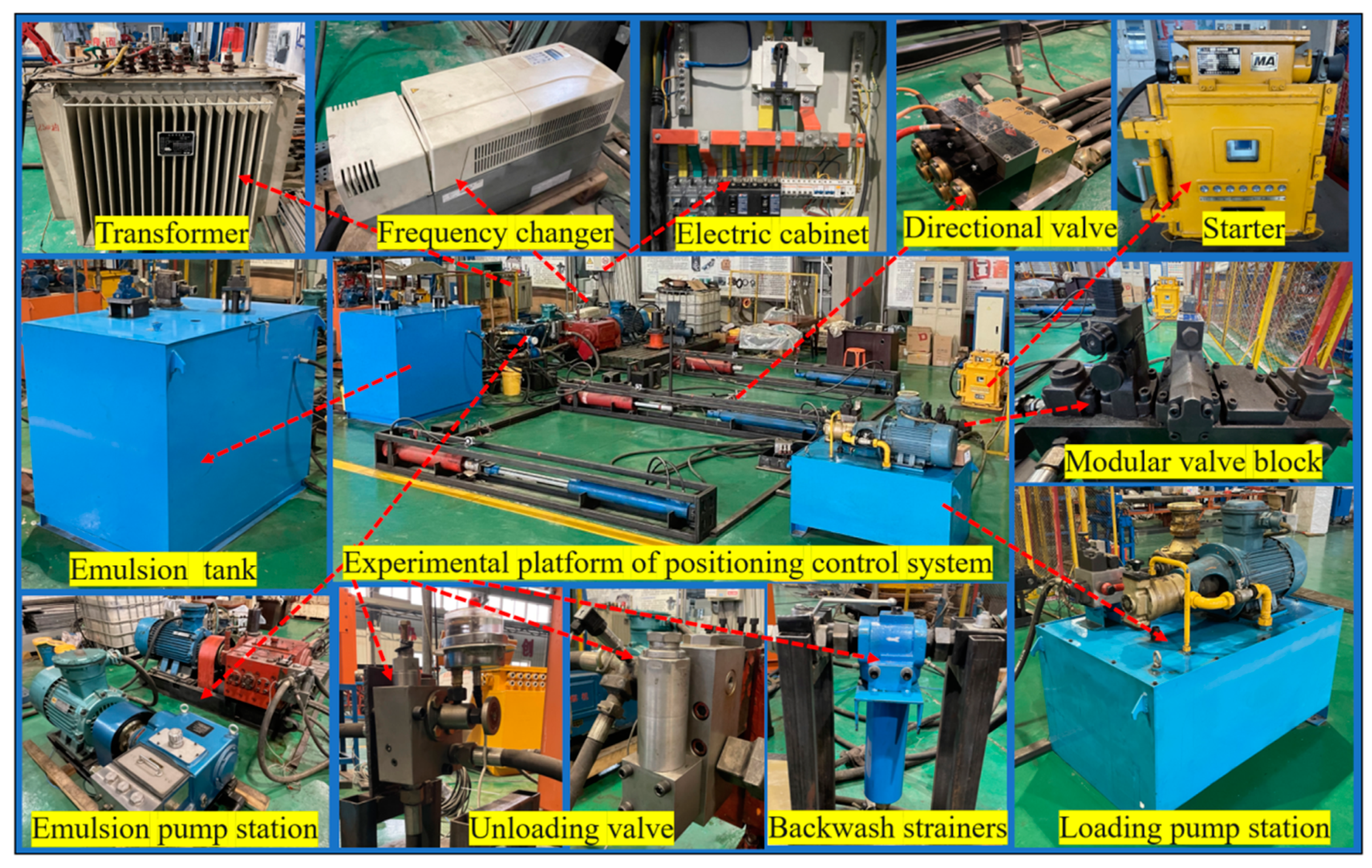
In the experimental platform, a loading system was first designed for force loading experiments. The oil supply pressure of the loading pump source is adjusted to a small value by adjusting the set pressure of the overflow valve, which mainly plays the role of oil replenishment. The proportional relief valve is installed on the oil return side of the oil circuit and mainly plays the role of back pressure. By adjusting different back pressure, different loading force loading can be realized. The experimental platform is built according to Figure 1, and the physical diagram of the control system test bed is shown in Figure 10.
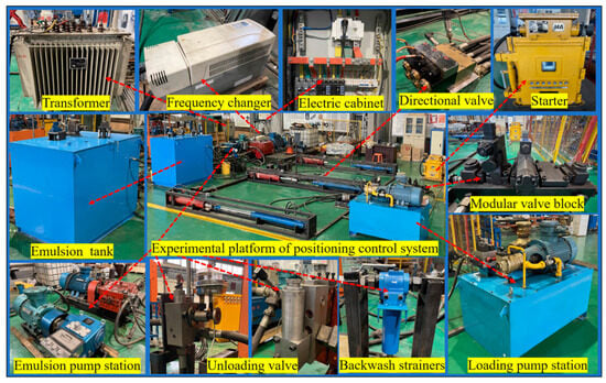
Figure 10.
Experimental platform of positioning control system.
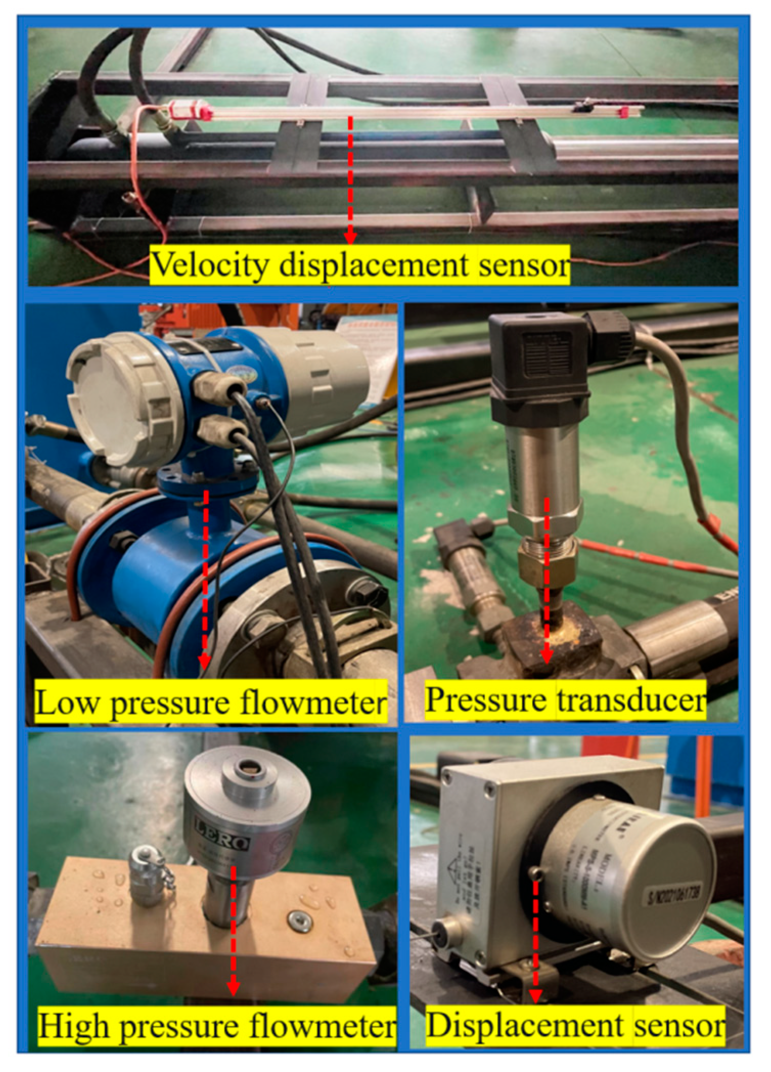
The piston diameter of the single-rod cylinder is 110 mm, the rod diameter of the single-rod cylinder is 80 mm, and the stroke is 1000 mm. The process of pushing the scraper conveyor and pulling hydraulic support is simulated by the extension and retraction of the pushing cylinder. The displacement and velocity of the piston are measured by an external magnetostrictive sensor (MTS), the hydraulic cylinder is controlled by the electrohydraulic directional control valve, and the throttle valve is used for speed regulation. Three pressure sensors (MIK-P300) are used to measure the pressure at ports P, A, and B of the electrohydraulic directional control valve, and a high-pressure flowmeter (CT300) is used to measure the system flow. The sensors used in the experiment are shown in Figure 11.
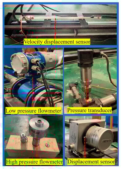
Figure 11.
Various types of sensors.
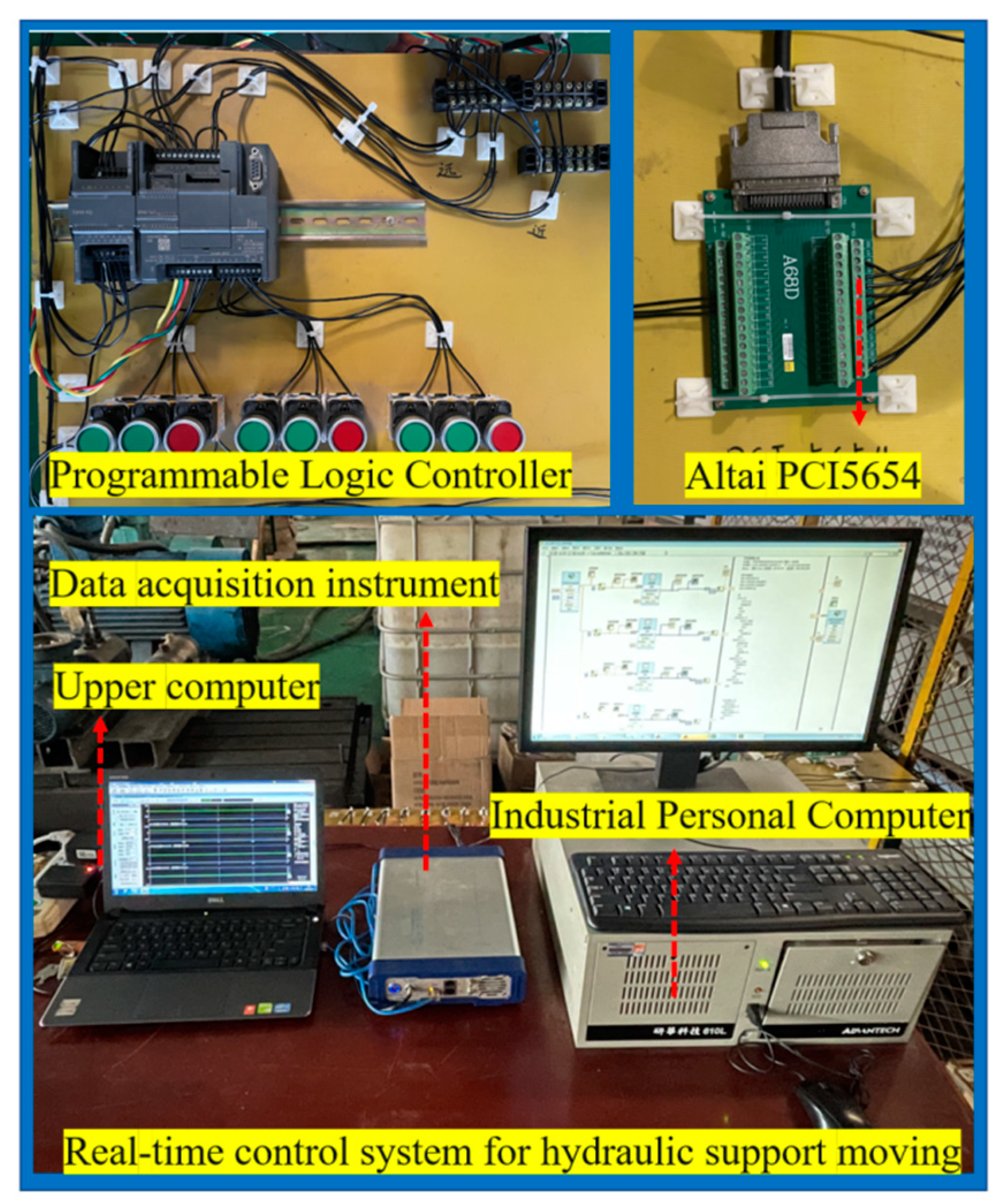
Figure 12 shows the real-time measurement and control system used in the control system test platform. The hardware of the measurement and control system is mainly composed of the lower computer (Advantech 610L industrial computer), the upper computer (PC), Altai PCI5654, and the PLC controller. The system software is the Simulink/real-time real-time control system in MATLAB(R2022a) software. The control algorithm involved is compiled in the MATLAB environment, and then the code is downloaded to the real-time controller. The collected signal is calculated by the compiled control strategy, and the calculated voltage output signal is output by PLC to control the electrohydraulic directional control valve. In addition, in order to solve the noise problem of the signal in the process of acquisition, a filter module is added to the program to process the acquired signal.

Figure 12.
Real-time control system for hydraulic support moving.
5.2. Switching Law Modification
However, the following problems may exist in the actual process:
(1) Due to the constraint of switching frequency, if the time taken for to reach zero is less than the minimum switching interval, the control command cannot perform zero-value switching at the moment when is equal to zero, which eventually leads to a large positioning error, the need for readjustment, or even the phenomenon of repeated switching.
Therefore, when the control signal is in a nonzero state value, zero-value switching can only be carried out when the time when reaches zero is greater than the minimum switching interval. The increment of at this time can be expressed as:
In the above formula, is a positive constant, indicating the maximum value of in the feasible speed region, and is the maximum pressure of the oil inlet cavity.
(2) Because of the actual working condition of high pressure and large flow, it is not practical to switch to zero-value when is exactly equal to zero. Considering the requirement of positioning control accuracy of hydraulic support in the fully mechanized working face, the limitation of the actual controller frequency, random error in the measurement process, prediction error, and other factors, the final position is allowed to have an error within a certain range.
Considering the two aspects, the switching control law in the final simplified case is expressed as:
where is a nonzero constant, which is related to the positioning accuracy required by the actual working condition.
5.3. Experimental Results and Discussion
The parameters involved in the experiment are shown in Table 1, Table 2, Table 3 and Table 4. In order to verify the correctness of the simulation analysis and the effectiveness of the proposed control strategy, the experimental process is basically consistent with the simulation process. Conduct positioning tests on fixed target positions at different steady-state speeds. A square-wave signal with a target position of 0.025 Hz, with target values of 300 mm and 600 mm, respectively.
Table 4.
Parameter table of switching control law.
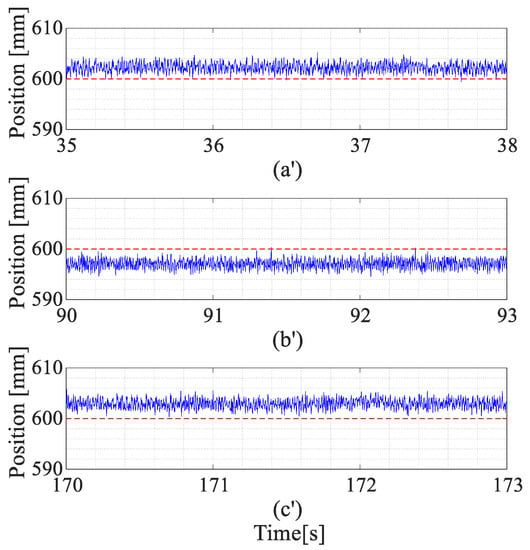
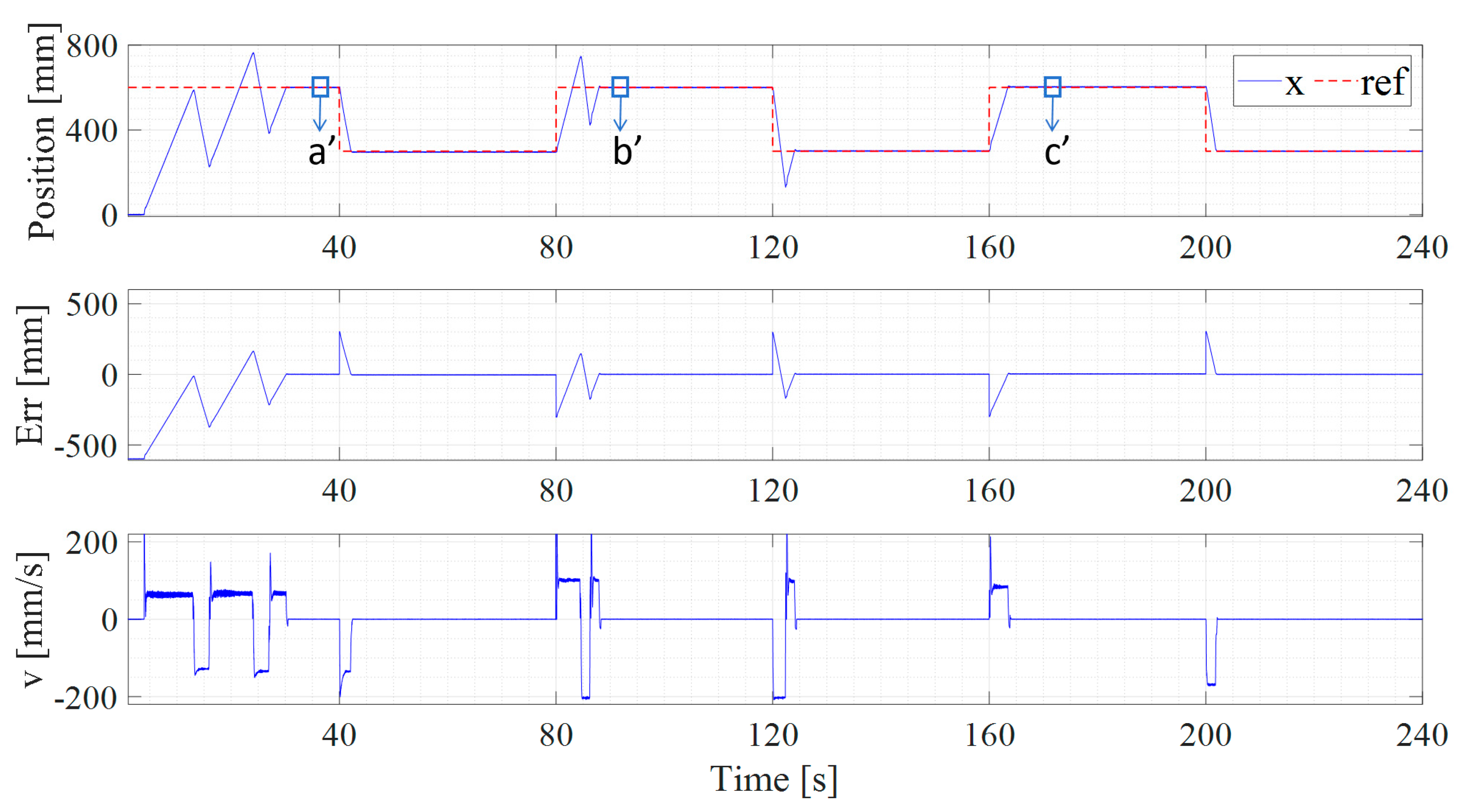
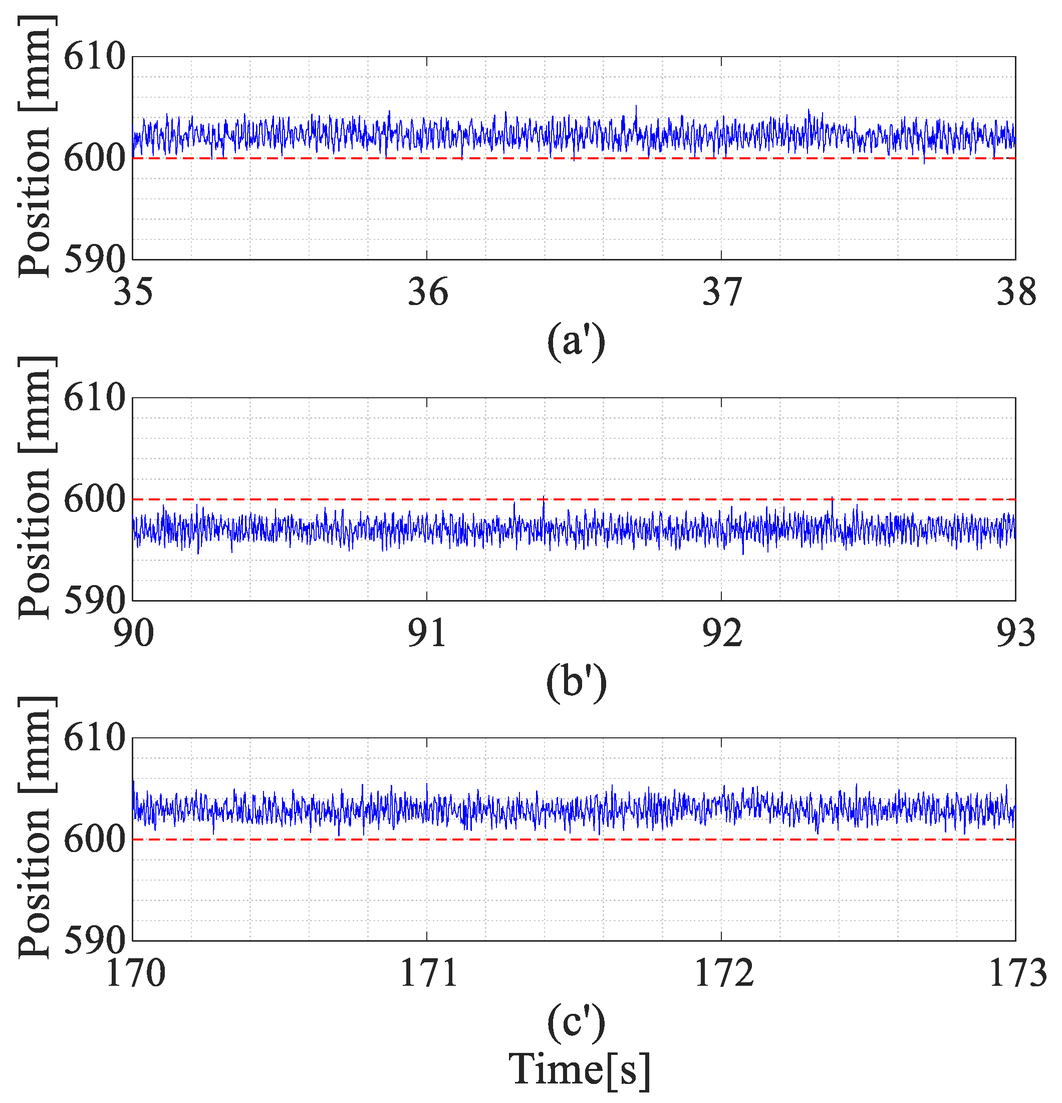
Figure 13 shows a positioning control state at a fixed target position. Figure 14 shows the local enlarged image corresponding to the positions “a′”, “b′”, and “c′” in Figure 13. Compared with the simulation results, a long adjustment process occurs in the initial stage, but stable positioning control can still be achieved after t1 (30 s) after many zero switchings.
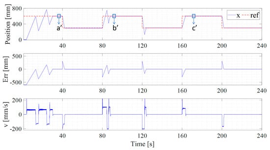
Figure 13.
Positioning control curve of fixed target position.
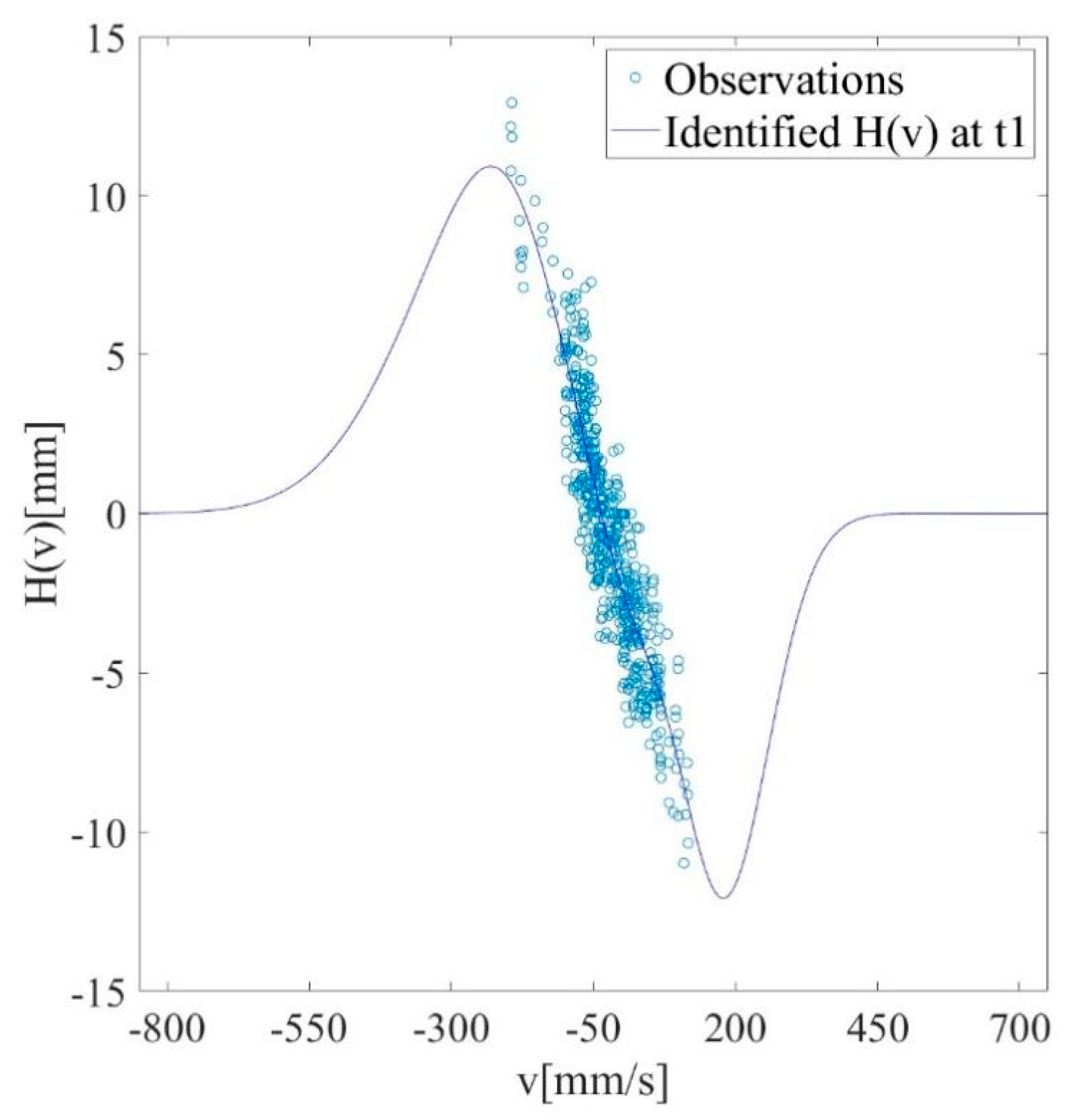
As shown in Figure 15, the experimental fitting result of the target trajectory at t1 (30 s) is consistent with the simulation fitting result, which shows that the improved GGAP-RBF can better fit the observed data obtained by the experiment.
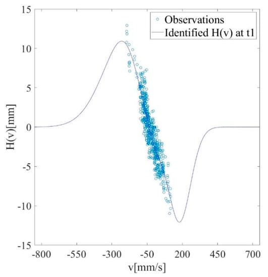
Figure 15.
Observed data of target track at t1 in the experiment and improved GGAP-RBF target track fitting results.
At the same time, the steady speed of the hydraulic cylinder is adjusted to a larger input value at t2 (80 s), and a larger fluctuation occurs in this process at first, because the target trajectory in the speed range is not observed, but with the increase in experimental observation data, stable positioning control is finally realized at t3 (87 s), because the learning algorithm obtains a better identification result through training with enough observation data. As shown in Figure 16, the experimental fitting result of the target trajectory at t3 (87 s) is consistent with the simulation fitting result. The result shows that the improved GGAP-RBF quickly adjusts the network parameters through the newly obtained observation data and finally fits all the obtained observation data well.
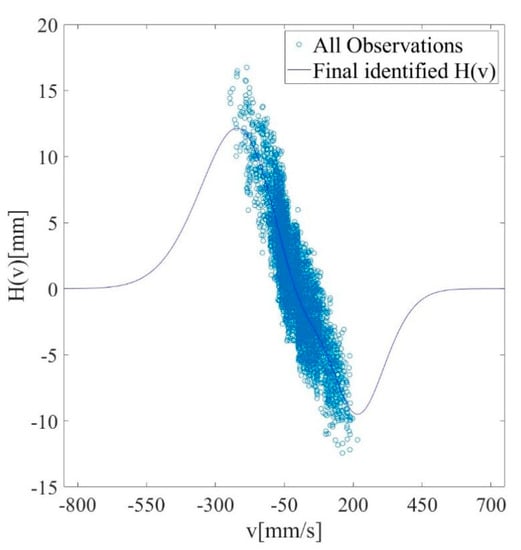
Figure 16.
Observed data of target track at t3 in the experiment and improved GGAP-RBF target track fitting results.
At t4 (160 s), the steady-state speed is adjusted again, but the system will always be in a stable positioning control state, because the prediction model has been well corrected and the target trajectory has been well fitted. Due to the setting of allowable error values in the experiment, the hydraulic cylinder will stop at a fixed value within the error range each time, without stable fluctuations near the target position as in the simulation. In addition, some complex dynamics appeared in the whole experiment process, which did not appear in the simulation. The above situation is due to the complexity of the actual movement of the cylinder on the one hand, and the error caused by measuring equipment and measuring means on the other hand.
To sum up, although the actual measurement results and simulation results are different in dynamic details, but can better reproduce the overall process of change in the simulation, the tracking situation is basically consistent with the simulation effect, so the simulation model is a good explanation of the experimental phenomenon, and the experiment also verifies the effectiveness of the simulation analysis. In addition, according to the requirement of the whole straightness of the hydraulic support in the fully mechanized coal mining face, the positioning error is properly adjusted within the allowable error range, which can reduce the switching frequency and improve the working efficiency of the moving support.
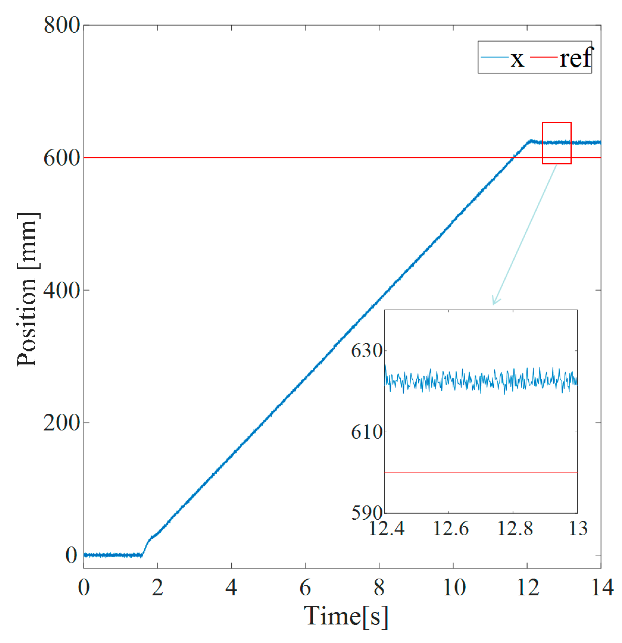
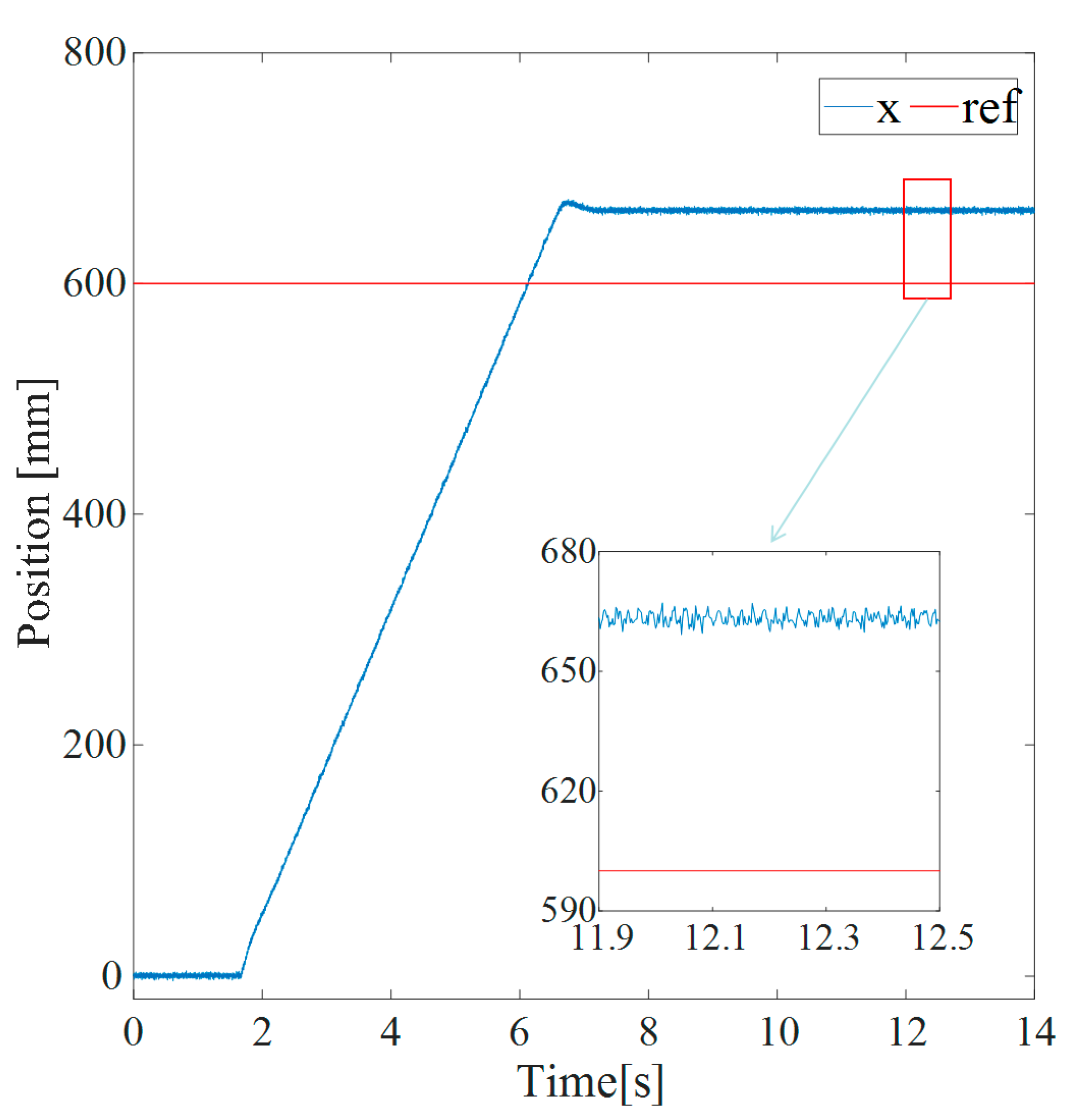
In order to better demonstrate the effectiveness of the proposed control strategy, a positioning control experiment was conducted using existing simple logic control methods, and a comparative analysis was conducted with the positioning error of the proposed control strategy. Figure 17 and Figure 18 show the experimental results of using simple logic positioning control under different supply flow rates when the target position is 600 mm. From the figure, it can be seen that when the system’s liquid supply flow rate is 32 L/min, its final position is 623 mm, and when the system supply flow rate is 72 L/min, its final position is 662 mm. The positioning errors under these two flow rates are 23 mm and 62 mm, respectively, which are much greater than the positioning error in the positioning control method proposed in this article (error threshold 15 mm). As the supply flow rate continues to increase, the positioning error caused by simple logic positioning control will also increase. In summary, the designed control strategy has higher positional accuracy compared to traditional control, which is beneficial for improving the straightness of the working face.
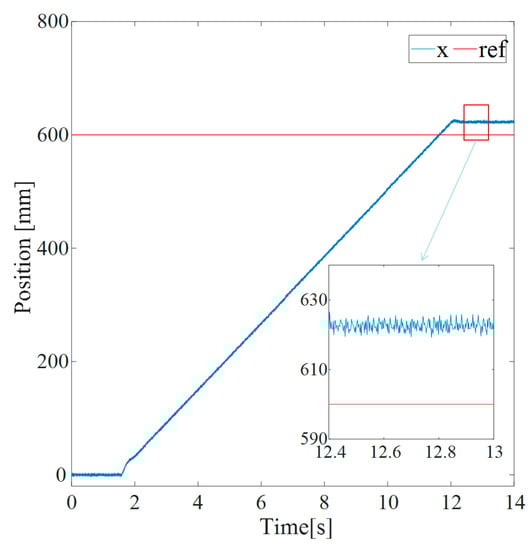
Figure 17.
Simple logic positioning control results at 32 L/min.
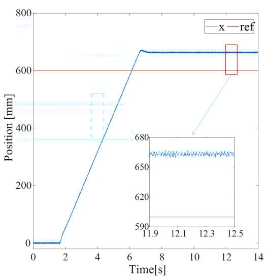
Figure 18.
Simple logic positioning control results at 72 L/min.
6. Conclusions
- (1)
- Aiming at the positioning control problem of hydraulic support pushing system in fully mechanized coal mining face, a positioning control strategy based on online predictive feedback is proposed. This scheme combines intelligent algorithms with hydraulic engineering, utilizing learning algorithms to identify the predictive models required for hydraulic systems in real time, and continuously providing accurate predictive information for switching control methods through online learning algorithms. Ultimately, the hydraulic cylinder is controlled to the target position in the optimal way, solving the problem of input constraints, delay, and system nonlinearity in positioning control of electrohydraulic directional valves and the problem of low positioning control accuracy caused by uncertainty. This solves the problem of low positioning control accuracy caused by input constraint, delay, system nonlinearity, and uncertainty in the positioning control of the electrohydraulic directional control valve.
- (2)
- The positioning control method proposed in this article first establishes a state prediction model after zero-value switching occurs, followed by online fitting of the target trajectory, and finally determines the optimal switching control method by establishing the relationship between the two. In the above process, the target trajectory is fitted online using the improved GGAP-RBF algorithm, and the prediction model is identified online using the recursive least-squares method with a forgetting factor.
- (3)
- Through simulation analysis and experimental research, we can conclude that the predicted model is in good agreement with the actual model, and the identification results converge quickly. The proposed improved GGAP-RBF algorithm can stably and quickly perform online data fitting, and the online learning algorithm provides precise information for positioning control methods. Therefore, the proposed positioning control scheme can achieve the control accuracy required for the actual working conditions of the hydraulic support pushing system in the fully mechanized mining face with a small number of switches.
- (4)
- The positioning control strategy based on online predictive feedback proposed in this article solves the problem of low positioning control accuracy caused by the imperfect characteristics of the electrohydraulic directional valve in the hydraulic support pushing system and has shown a good positioning control effect in experimental research, but these are only carried out on the premise of meeting the accuracy requirements of coal mine underground positioning. In order to facilitate the design of the controller, this article simplifies the design of the controller while meeting the positioning requirements. Therefore, if this method is to be applied to other occasions with high precision requirements for positioning control, it is necessary to design more effective identification methods for dynamic model identification.
Author Contributions
Conceptualization, T.H.; Data curation, T.H., P.X., B.Z. and Y.P.; Funding acquisition, Z.K. and J.W.; Project administration, Z.K. and J.W.; Software, Z.K. and J.W.; Supervision, Z.K. and J.W.; Writing—Original draft preparation, T.H.; Writing—review and editing, T.H. All authors have read and agreed to the published version of the manuscript.
Funding
His research was funded by the National Natural Science Foundation of China “Study on high pressure, large flow and high water-based digital valve and its control method in mining” (Project No. U1910212).
Institutional Review Board Statement
Not applicable.
Informed Consent Statement
Not applicable.
Data Availability Statement
Not applicable.
Conflicts of Interest
The authors declare no conflict of interest.
References
- Wang, G.; Ren, H.; Zhao, G.; Gong, S.X.; Du, Y.B.; Xue, Z.X.; Pang, Y.H.; Zhang, X. Digital model and giant system coupling technology system of smart coal mine. J. China Coal Soc. 2022, 47, 61–74. [Google Scholar]
- Ren, H.; Gong, S.; Liu, X.; Lv, Y.; Wen, Z.; Liu, W.; Zhang, S. Research and application on key techniques of intelligent mining for kilo-meter coal mine. Coal Sci. Technol. 2021, 49, 149–158. [Google Scholar]
- Ren, H.; Meng, X.; Li, Z. Study on key technology of intelligent control system applied in 8m large mining height fully-mechanized face. Coal Sci. Technol. 2017, 45, 37–44. [Google Scholar]
- Vu, T.T. Solutions to prevent face spall and roof falling in fully mechanized longwall at underground mines, Vietnam. Min. Miner. Depos. 2022, 16, 127–134. [Google Scholar] [CrossRef]
- Nehrii, S.; Nehrii, T.; Volkov, S.; Zbykovskyy, Y.; Shvets, I. Operation complexity as one of the injury factors of coal miners. Min. Miner. Depos. 2022, 16, 95–102. [Google Scholar] [CrossRef]
- Wang, J.; Apel, D.B.; Dyczko, A.; Walentek, A.; Prusek, S.; Xu, H.; Wei, C. Analysis of the damage mechanism of strainbursts by a global-local modeling approach. J. Rock Mech. Geotech. Eng. 2022, 14, 1671–1696. [Google Scholar] [CrossRef]
- Peng, S.; Scheidl, R. The use of a hydraulic DC-DC converter in the actuation of a robotic leg. In Proceedings of the 2013 IEEE/RSJ International Conference on Intelligent Robots and Systems (IROS), Tokyo, Japan, 3–7 November 2013; pp. 5859–5864. [Google Scholar]
- Guglielmino, E.; Semini, C.; Yang, Y.; Caldwell, D.; Kogler, H.; Scheidl, R. Energy Efficient Fluid Power in Autonomous Legged Robotics. In Proceedings of the ASME 2009 Dynamic Systems and Control Conference, Hollywood, CA, USA, 12–14 October 2009; pp. 847–854. [Google Scholar]
- Van Varseveld, R.B.; Bone, G.M. Accurate position control of a pneumatic actuator using on/off solenoid valves. IEEE/ASME Trans. Mechatron. 1997, 2, 195–204. [Google Scholar] [CrossRef]
- Bury, P.; Stosiak, M.; Urbanowicz, K.; Kodura, A.; Kubrak, M.; Malesińska, A. A Case Study of Open- and Closed-Loop Control of Hydrostatic Transmission with Proportional Valve Start-Up Process. Energies 2022, 15, 1860. [Google Scholar] [CrossRef]
- Stosiak, M.; Karpenko, M.; Deptuła, A.; Urbanowicz, K.; Skačkauskas, P.; Deptuła, A.M.; Danilevičius, A.; Šukevičius, Š.; Łapka, M. Research of Vibration Effects on a Hydraulic Valve in the Pressure Pulsation Spectrum Analysis. J. Mar. Sci. Eng. 2023, 11, 301. [Google Scholar] [CrossRef]
- Hodgson, S.; Tavakoli, M.; Pham, M.T.; Leleve, A. Nonlinear Discontinuous Dynamics Averaging and PWM-Based Sliding Control of Solenoid-Valve Pneumatic Actuators. IEEE/ASME Trans. Mechatron. 2015, 20, 876–888. [Google Scholar] [CrossRef]
- Kogler, H.; Scheidl, R. Linear motion control with a low-power hydraulic switching converter–Part II: Flatness-based control. Proc. Inst. Mech. Eng. Part I J. Syst. Control Eng. 2015, 229, 818–828. [Google Scholar] [CrossRef]
- Gradl, C.; Scheidl, R. A Basic Study on the Response Dynamics of Pulse-Frequency Controlled Digital Hydraulic Drives. In Fluid Power Systems Technology; American Society of Mechanical Engineers: New York, NY, USA, 2013; p. V001T01A022. [Google Scholar]
- Wang, F.; Gu, L.; Chen, Y. A Hydraulic Pressure-Boost System Based on High-Speed On-Off Valves. IEEE/ASME Trans. Mechatron. 2013, 18, 733–743. [Google Scholar] [CrossRef]
- Nguyen, T. Accurate Sliding-Mode Control of Pneumatic Systems Using Low-Cost Solenoid Valves. IEEE/ASME Trans. Mechatron. 2007, 12, 216–219. [Google Scholar] [CrossRef]
- Paul, A.K.; Mishra, J.E.; Radke, M.G. Reduced order sliding mode control for pneumatic actuator. IEEE Trans. Control Syst. Technol. 1994, 2, 271–276. [Google Scholar] [CrossRef]
- Scheidl, R.; Gradl, C.; Kogler, H.; Foschum, P.; Plöckinger, A. Investigation of a Switch—Off Time Variation Problem of a Fast Switching Valve. In Fluid Power Systems Technology; American Society of Mechanical Engineers: New York, NY, USA, 2014; p. V001T01A033. [Google Scholar]
- Liu, Z.; Gao, Q.; Deng, G.; Niu, H.L.; Li, J.Y. The position control of hydraulic cylinder based on high-speed on-off valve. Int. J. Model. Identif. Control 2014, 22, 54–67. [Google Scholar] [CrossRef]
- Wu, G. New Practical Electro-Hydraulic Proportional Technique; Zhejiang University Press: Hangzhou, China, 2006. [Google Scholar]
- Wang, C. Hydraulic Servo Control System; China Machine Press: Beijing, China, 1989. [Google Scholar]
- Chen, L.J.; Peng, Z.Q.; Gao, W.; Ai, C. Research on position control of direct acting high frequency response proportional valve. Hydraul. Pneum. 2021, 2, 36–41. [Google Scholar]
- Mao, R. Research on Nonlinear Characteristics and Control Methods of Proportional Valve Controlled Hydraulic Cylinder System; Beijing University of Technology: Beijing, China, 2015. [Google Scholar]
- Wang, L.P.; Peng, T.H. Research on electro-hydraulic proportional height regulation system based on single neuron PID control. Coal Eng. 2019, 51, 130–134. [Google Scholar]
- Zhao, S.; Song, T.; Zhou, Y.; Zhang, X. Application of iterative learning method in position control of on-off hydraulic valve. J. Xi’an Jiaotong Univ. 2003, 37, 523–526. [Google Scholar]
- Yang, Y.; Wang, Y.; Song, Y. Research on positioning control of opening-closing mechanism of injection molding machine based on alternative learning. China Mech. Eng. 2008, 19, 2152–2155. [Google Scholar]
- Zepeng, N.; Lixian, Z.; Patrizio, C. Semi-Markov Jump Linear Systems with Incomplete Sojourn and Transition Information: Analysis and Synthesis. IEEE Trans. Autom. Control 2020, 65, 159–174. [Google Scholar]
- Nie, L.; Cai, B.; Lu, S.; Qin, H.; Zhang, L. Finite-time switched LPV control of quadrotors with guaranteed performance. J. Frankl. Inst. 2021, 358, 7032–7054. [Google Scholar] [CrossRef]
- Yang, J.; Ning, Z.; Zhu, Y.; Zhang, L.; Lam, H.K. Semi-Markov jump linear systems with bi-boundary sojourn time: Anti-modal-asynchrony control. Automatica 2022, 140, 110270. [Google Scholar] [CrossRef]
- Huang, G.-B.; Saratchandran, P.; Sundararajan, N. A Generalized Growing and Pruning RBF (GGAP-RBF) Neural Network for Function Approximation. IEEE Trans. Neural Netw. 2005, 16, 57–67. [Google Scholar] [CrossRef] [PubMed]
- Wang, Y.; Huang, G.-B.; Saratchandran, P.; Sundararajan, N. Time series study of GGAP-RBF network: Predictions of Nasdaq stock and nitrate contamination of drinking water. In Proceedings of the 2005 IEEE International Joint Conference on Neural Networks, Montreal, QC, USA, 31 July–4 August 2005; Volume 5, pp. 3127–3132. [Google Scholar]
- Li, S.; Chen, Q.; Huang, G.-B. Dynamic temperature modeling of continuous annealing furnace using GGAP-RBF neural network. Neurocomputing 2006, 69, 523–536. [Google Scholar] [CrossRef]
- Qiao, J.-F.; Han, H.-G. Identification and modeling of nonlinear dynamical systems using a novel self-organizing RBF-based approach. Automatica 2012, 48, 1729–1734. [Google Scholar] [CrossRef]
- Sotiropoulos, P.; Aspragathos, N. Neural networks to determine task oriented dexterity indices for an underwater vehicle-manipulator system. Appl. Soft Comput. 2016, 49, 352–364. [Google Scholar] [CrossRef]
- Cetinkunt, S. Mechatronics with Experiments; John Wiley & Sons: Hoboken, NJ, USA, 2015. [Google Scholar]
- Marton, L.; Fodor, S.; Sepehri, N. A practical method for friction identification in hydraulic actuators. Mechatronics 2011, 21, 350–356. [Google Scholar] [CrossRef]
- Tran, X.; Khaing, W.; Endo, H.; Yanada, H. Effect of friction model on simulation of hydraulic actuator. Proc. Inst. Mech. Eng. I J. Syst. Control Eng. 2014, 228, 690–698. [Google Scholar] [CrossRef]
- Lischinsky, P.; Canudas-de-Wit, C.; Morel, G. Friction compensation for an industrial hydraulic robot. IEEE Control Syst. Mag. 1999, 19, 25–32. [Google Scholar]
- Owen, W.S.; Croft, E.A. The reduction of stick-slip friction in hydraulic actuators. IEEE/ASME Trans. Mechatron. 2003, 8, 362–371. [Google Scholar] [CrossRef]
- Ljung, L. Asymptotic behavior of the extended Kalman filter as a parameter estimator for linear systems. IEEE Trans. Autom. Control 1979, 24, 36–50. [Google Scholar] [CrossRef]


Disclaimer/Publisher’s Note: The statements, opinions and data contained in all publications are solely those of the individual author(s) and contributor(s) and not of MDPI and/or the editor(s). MDPI and/or the editor(s) disclaim responsibility for any injury to people or property resulting from any ideas, methods, instructions or products referred to in the content. |
© 2023 by the authors. Licensee MDPI, Basel, Switzerland. This article is an open access article distributed under the terms and conditions of the Creative Commons Attribution (CC BY) license (https://creativecommons.org/licenses/by/4.0/).