1. Introduction
As the Internet of Things (IoT) applications expand into many different domains, it is important to consider the reliability of these services. The sensors’ physical
location and
sensing coverage are two primary services of IoT applications, and these services must be delivered reliably for the IoT to be successful. In this research, we concentrate on improving IoT localization and sensing coverage by building upon our previous work found in [
1].
The location of sensors and sensing coverage are directly influenced by the strategic deployment of nodes, ensuring efficient data collection and monitoring.
The methodologies for deploying sensor nodes depend on various factors, including the specific application, dimensions of the targeted area, degree of knowledge about the node density and positions, as well as the accessibility of the target region. Generally, two primary deployment approaches can be identified: deterministic and random. The deterministic deployment approach considers several predetermined factors, such as network topology, sensor positioning, inter-sensor distance, and density. This method of sensor deployment offers greater control over resource constraints. Energy consumption optimization is typically the primary metric in many deterministic deployment strategies [
2,
3,
4]. A common example of this type is grid-based deployment, which includes hexagonal, square, and equilateral triangular patterns. The equilateral triangle configuration provides full coverage while minimizing the required sensor nodes [
5]. The Art Gallery problem is a traditional problem of this type of deployment [
6], where the objective is to position the minimum number of sensors to ensure complete monitoring of every point in the gallery.
In contrast to deterministic deployment, random deployment lacks information regarding the network topology and the specific positions of sensors. This mode of deployment is well-suited for extensive networks in harsh and remote environments, such as forests, mountainous regions, and hazardous locations, such as chemical leak sites and nuclear facilities. Nevertheless, random deployment cannot ensure complete sensing coverage [
7]. Continuously maintaining all sensors in an active state results in rapid energy consumption, ultimately leading to network disconnection. As a consequence, some regions within the network may not receive sensing reports [
8,
9].
In both deployment methodologies, the communication between sensor nodes themselves and sensor and anchor nodes can be classified as either single-hop or multi-hop. Due to the increased transmission power required for longer distances, sensors with limited power reserves utilize shorter transmission ranges to conserve energy. As a result, the collective sensing data is transmitted from the originating node to the destination through multiple intermediate nodes or relays. Conversely, sensor nodes equipped with a continuous power supply maintain the capacity for single-hop communication with a sink node, enabling direct peer-to-peer exchanges.
1.1. Localization in IoT Networks
The Internet of Things (IoT) establishes a large-scale network composed of diverse sensor-enabled nodes. Wireless Sensor Networks (WSNs) are one of the primary drivers of IoT advancements. Typically, a WSN contains thousands of low-cost, low-power sensor nodes. These networks have numerous applications, including military surveillance, wildlife tracking, and environmental monitoring. Determining the sensors’ physical positions is crucial for maintaining trusted IoT-based services.
Localization is fundamental to data collection and routing planning, enabling efficient information delivery to the target station. For instance, autonomous vehicles would face significant safety risks without precise positioning, resulting in increased accidents. Similarly, incorrect data from sensors in wildfire monitoring systems would undermine the service quality. Sensor localization methods can be categorized as anchor-based or anchor-free approaches.
Anchor nodes have more capabilities than sensors and are aware of their actual positions. Consequently, they serve as reference points for determining the unknown locations of other sensors. Conversely, anchor-free localization leverages tools such as relative positioning, mapping, and embedded GPS clients. In this study, we adopt an anchor-based strategy to localize IoT sensors. Specifically, we intend to utilize time of arrival (ToA) or time difference of arrival (TDoA) alongside the path loss model for signal measurements received at the sensor.
1.2. Sensing Coverage in IoT Networks
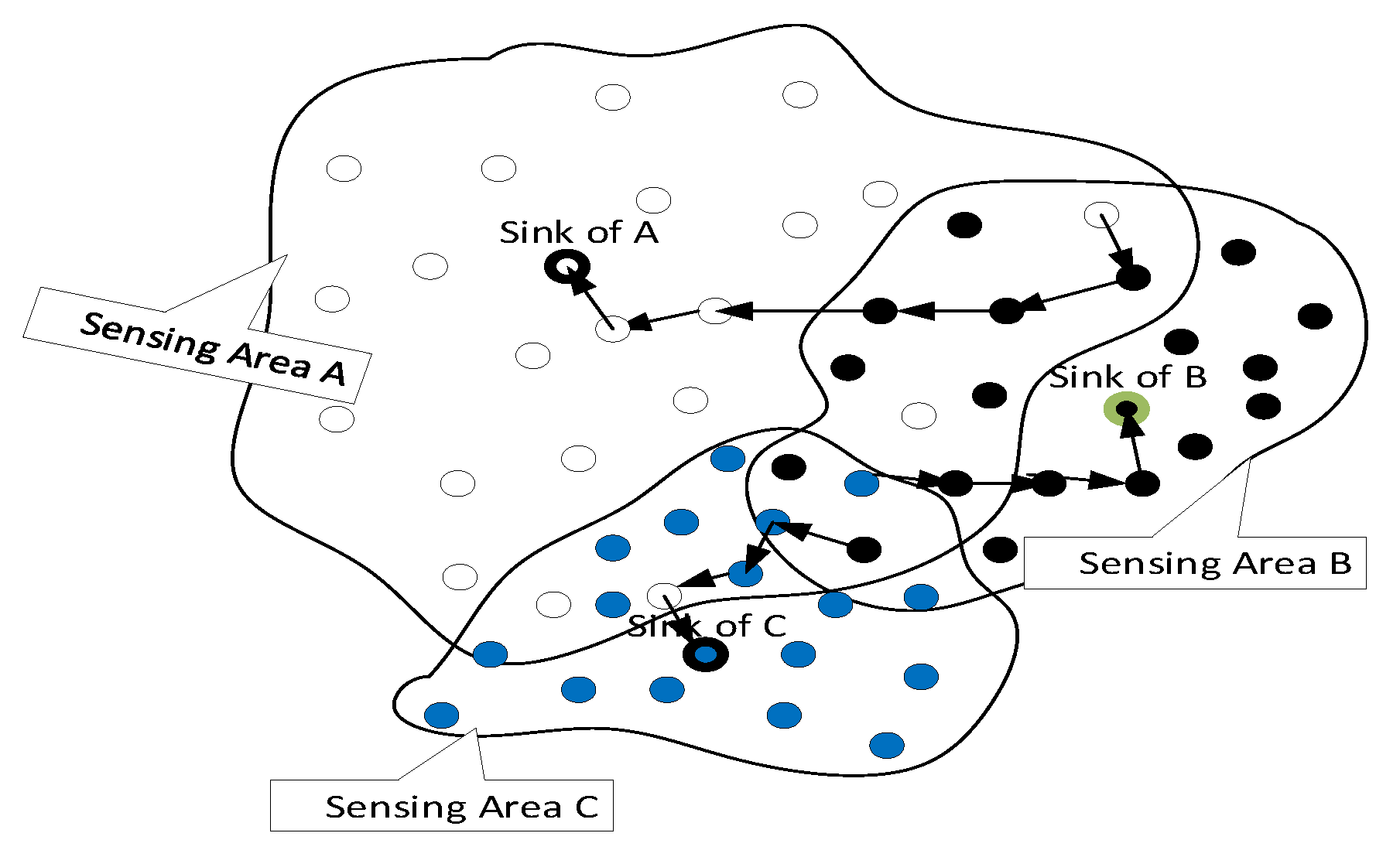
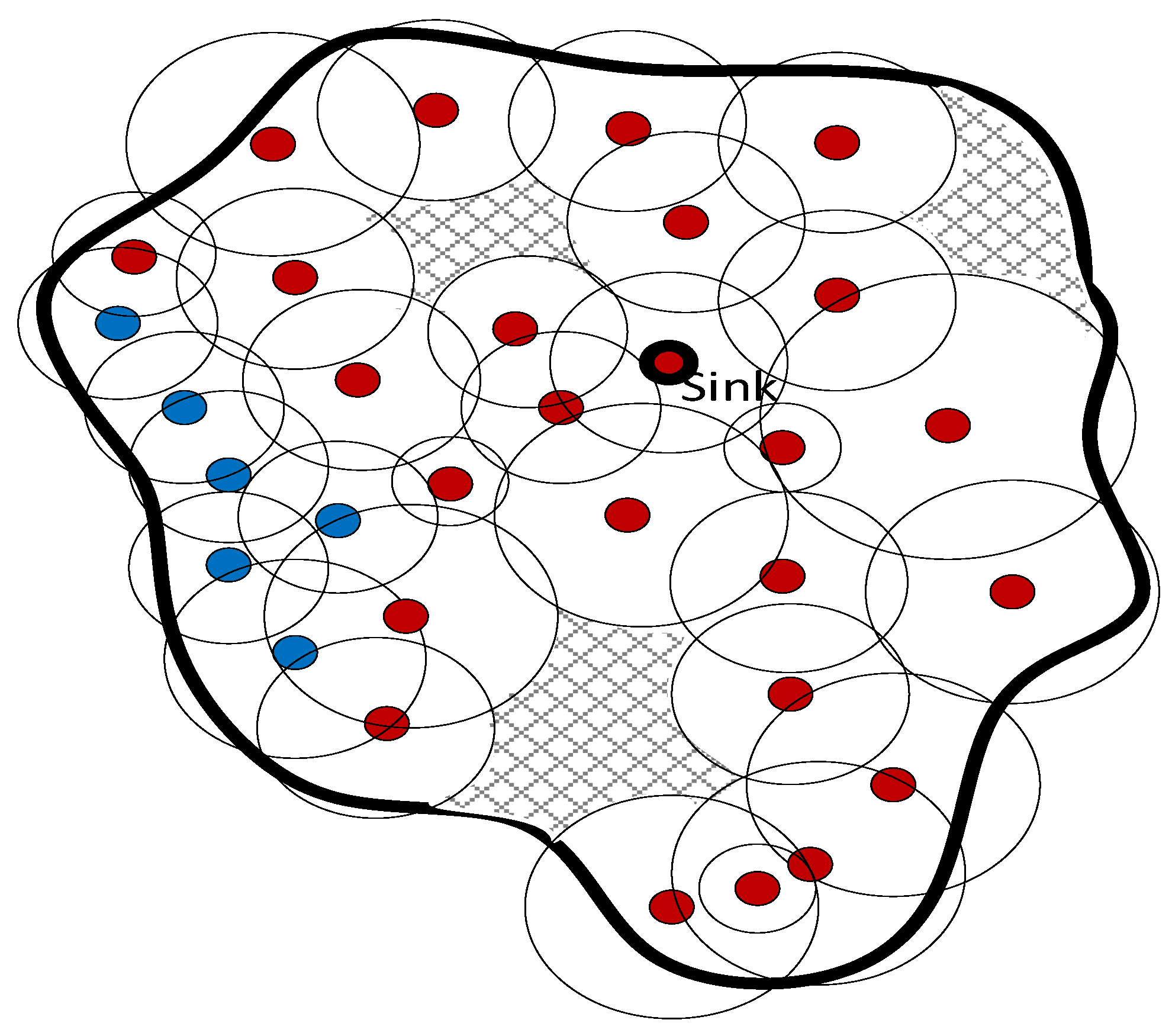
In a sensing field, a point is considered covered if it lies within the sensing proximity of a sensor node, meaning that the Euclidean distance between this point and any sensor node is less than the designated sensing range. Consequently, the sensing field may have either full or partial coverage. To address partial coverage, cooperative sensor networks can be employed, allowing for the deployment of sensor nodes belonging to multiple entities. For instance, when heterogeneous temperature sensors owned by three disparate sensing providers are deployed within a specified region, as illustrated in
Figure 1, they can be regarded as shared resources. Cooperation among these sensors can yield improved quality of service (QoS) while also enabling the incorporation of participatory sensors such as smartphones.
1.3. The Relationship between Localization and Sensing Coverage
Identifying the presence of coverage gaps and outlining them constitutes a significant obstacle in the IoT context. Coverage gaps arise when sensing fields exhibit incomplete coverage. The sensing coverage requirements of IoT applications vary; for instance, certain applications necessitate single-sensing coverage where a minimum of one sensor is needed to observe any point within the target zone. Conversely, other applications demand extensive coverage, which entails
k sensors to oversee each point within the area [
10].
Additionally, there exist multiple methods for approximating a sensor’s position; however, GPS is typically not employed due to energy constraints and the need for cost-effective sensors. Alternative solutions include anchor-based and anchor-free approaches, with the former being prevalent owing to its accuracy, while the latter offers rough localization precision. This study utilizes the anchor-based strategy.
The sensing coverage quality directly correlates with the credibility of aggregated sensing reports at the sink node; nevertheless, these reports are influenced by various error factors such as measurement discrepancies and anchor misplacement. These error components affect sensors’ location estimates, consequently leading to inaccurate location imprints on aggregated reports and ultimately degrading the quality of sensing services.
1.4. The Impact of Anchor Misplacement
Anchor misplacement pertains to the issue wherein an anchor node occupies a particular position, yet assumes it is situated elsewhere [
11]. For instance, an anchor node B erroneously assumes that it is located in a specific position while it is actually elsewhere. Numerous factors contribute to this issue, including cyberattacks, soil erosion, potential anchor displacement due to animal or human activities, or simply human error. Utilizing misplaced or inaccurate anchor nodes for localizing sensor nodes results in localization inaccuracies of sensor nodes [
11,
12]. Likewise, the quality of coverage is impacted as incorrectly estimated sensor locations yield invalid sensing reports. Consequently, the presence of anchor misplacement exacerbates sensing coverage. For example, in a smart agriculture system, anchor misplacement may prompt the inadvertent irrigation of perceived dry areas or the application of pesticides to healthy plants.
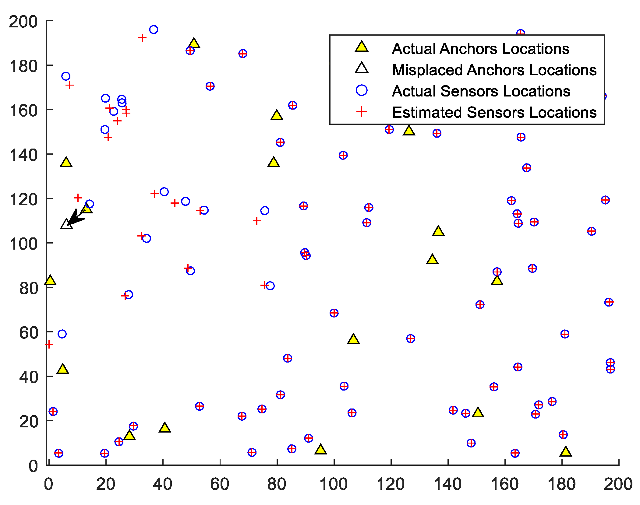
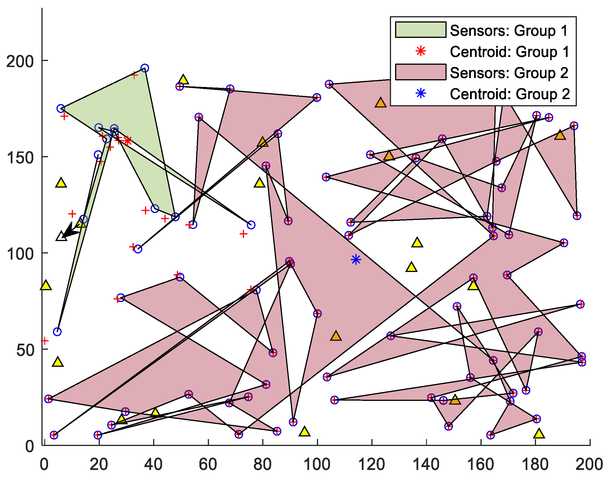
Figure 2 illustrates the effects of a misplaced anchor on localizing 80 sensor nodes and 20 anchor nodes within a 200 × 200 target field. The actual location of this specific anchor is (13.1, 115), while its perceived or declared location is (6.1, 108). The figure demonstrates the impacted sensors and their imprecise locations.
1.5. Motivation
Cooperative sensing offers substantial benefits to WSNs by enhancing sensing reliability and expanding sensing coverage [
12]. Nonetheless, current studies concerning sensing coverage typically assume an accurate anchor node position. In other words, literature research overlooks the anchor misplacement issue that affects both localization and sensing coverage.
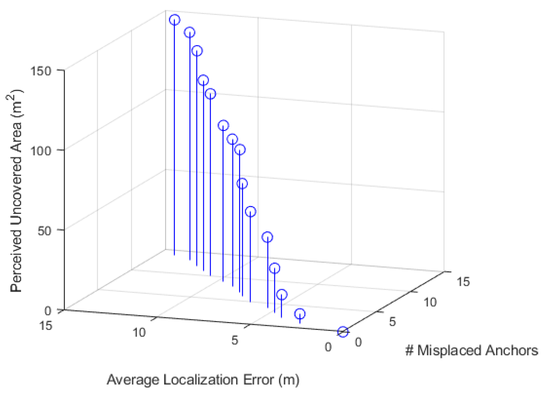
Figure 3 demonstrates the significance of mitigating the influence of anchor misplacement on localization precision and, consequently, on sensing coverage: an increased number of misplaced anchor nodes leads to a decline in IoT system service dependability.
Moreover, related research presumes that sensors are homogeneous and singularly affiliated with one sensing service provider. Relevant research focuses on deterministic sensor placement and deployment planning to achieve superior coverage and lengthen network lifetime [
13,
14]. In contrast, this study considers sensors as heterogeneous, randomly deployed, and associated with multiple sensing service providers.
In the domain of IoT security, anchor misplacement complications prove more perilous. For example, a hacker may target anchor nodes to tamper with their locations, resulting in inaccurate data collection and subsequent unreliability. Such issues become life-threatening when software/hardware errors or malicious attacks aim at autonomous vehicular sensor nodes, like LiDAR (Light Detection and Ranging). LiDAR technology is intended to supply precise geospatial data swiftly for informed decision-making. Consequently, the malicious alteration of LiDAR data such as modifying positioning coordinates or introducing inaccuracies in distances to nearby vehicles or objects causes severe safety concerns.
These points raise the following primary research questions: Q1: How does anchor misplacement influence the balance between detection latency and service reliability? Detection of misplaced anchors is more effective when more non-misplaced nodes participate in validating localization results for a fixed number of misplaced anchors executing sensor localization. However, an excess of validators magnifies communication overhead, subsequently increasing latency in the detection phase completion. Q2: What impact does anchor misplacement have on sensory data aggregation coverage? Q3: Can new types of coverage holes be identified and their areas quantified?
In this study, our objective is to address these research questions by devising a distributed, fast, and dependable method to detect misplaced anchors in WSNs. We strive to minimize anchor validators to achieve high reliability with reduced latency. Furthermore, we analyze the effects of anchor misplacement on sensory coverage in cooperative WSNs.
1.6. Contributions
The contributions of our work can be summarized as follows:
We propose an efficient framework for detecting anchor misplacement, which necessitates minimizing anchor validators’ involvement to ensure service reliability and minimal convergence latency;
We investigate and evaluate the presence of anchor misplacement issues in IoT systems and their effect on reliability. We show that using misplaced anchors for localizing sensors leads to imprecise positioning and compromised sensory data integrity;
Our study provides an in-depth analytical examination of how anchor misplacement impacts sensor localization and sensing coverage;
We suggest approaches for detecting coverage gaps resulting from anchor misplacement and estimating their size, along with determining upper and lower limits for these uncovered regions. By employing Delaunay Triangulation (DT), we divide the target sensing area into equilateral triangles. As intra-triangle coverage gaps are irregular, we aim to identify each gap locally and establish its boundaries. Our Intra-triangle Coverage (ITC) assessment method is decentralized, requiring only the vertices of each triangle to participate in calculations, thus ensuring scalability and energy efficiency;
We validate our proposed methodology’s efficacy under various conditions while demonstrating superior localization accuracy and reduced perceived uncovered regions.
To the best of our knowledge, this is the only research investigating IoT sensing coverage under anchor misplacement by locally identifying new coverage holes and quantifying their area.
The structure of the rest of this paper is organized as follows.
Section 2 provides an overview of fundamental definitions and models related to sensing coverage in WSNs, as well as various sensor deployment approaches. It also introduces the problem formulation and assumptions of our study. Preliminary findings utilizing the Voronoi Diagram (VD) and Delaunay Triangulation (DT) for efficient coverage are discussed in
Section 3. A comprehensive investigation of ITC is conducted in
Section 4. The effects of anchor misplacement on sensing coverage, along with a method for determining the lower and upper bounds of sensing coverage gaps, are presented in
Section 5. A resilient framework for detecting and mitigating the influence of misplaced anchors is described in
Section 6. Experimental results that validate our proposed framework and demonstrate its effectiveness are detailed in
Section 7. Finally,
Section 8 provides a conclusion and suggests future research directions.
2. System Model and Problem Description
Ensuring proper coverage is essential for reliable and effective sensing services. To achieve this, it is important to measure the accuracy of sensing reports in reflecting the physical surroundings of the target sensing field. Without adequate coverage, such services may become unreliable or obsolete. A list of notations and acronyms can be found in
Table 1.
2.1. Sensing Coverage Formulation
Sensing coverage holes are one of the main reasons that degrade the quality of sensing services. They exist when any sensing node does not cover some points in the sensing field. The following is a definition of sensing coverage.
Definition 1. Let S denote the target sensing field and , where is the number of sensing nodes. (, ) refers to the location of in a plane which is unknown initially. Each has estimated location (,) and a sensing range . Let p be a point in S, then p is covered if there is at least one such that p is within a distance of from . In other words, , where is the Euclidean distance between a and b.
2.2. Types of Sensing Coverage Holes under Anchor Misplacement
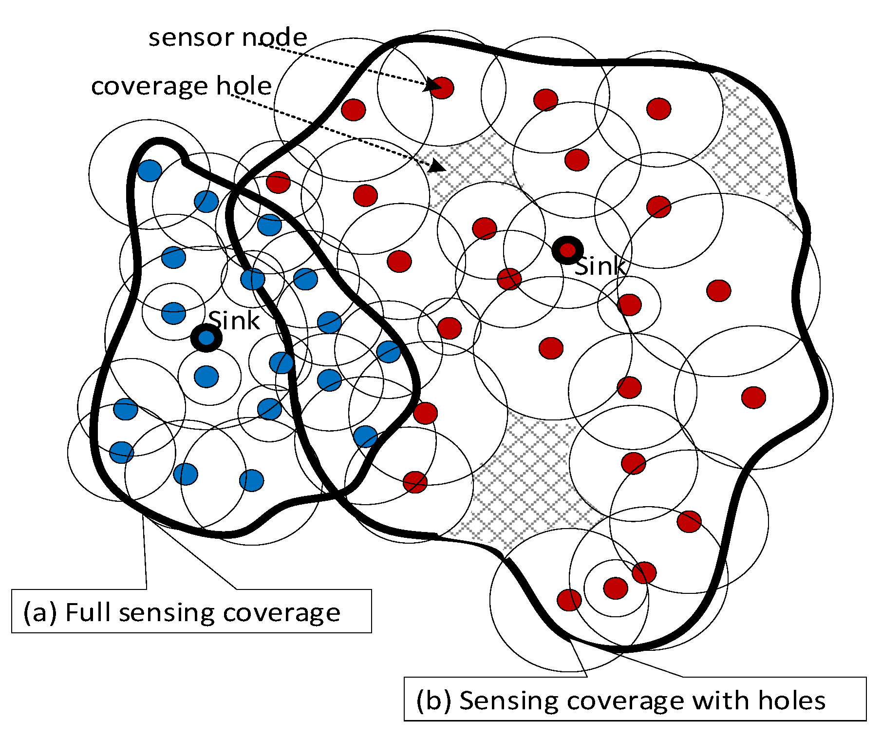
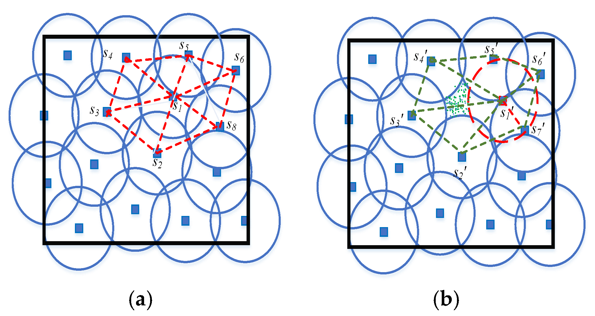
Figure 4 shows the full and partial coverage.
Anchor misplacement introduces new categories of coverage gaps, such as the perceived and hidden unreported actual coverage holes.
- (1)
In the case of the perceived coverage gap,
Figure 5a illustrates an ideal scenario in which sensor
is precisely localized, unaffected by anchor misplacement. Conversely,
Figure 5b demonstrates a situation where the localization of
is dependent on a misplaced anchor, subsequently generating a false coverage hole. This hole is present in two triangular regions:
and
.
- (2)
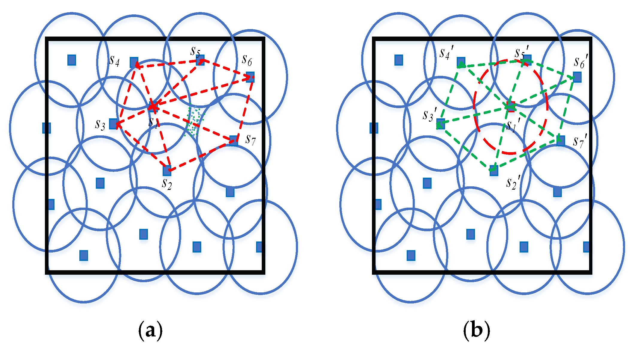
The hidden, unreported actual coverage gap is illustrated in
Figure 6.
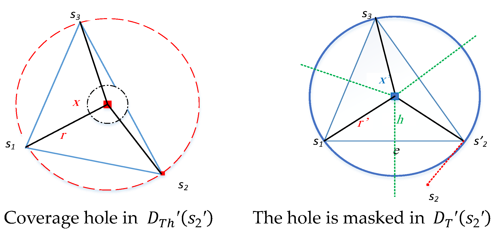
Figure 6a shows the presence of actual coverage holes within the triangular regions
and
. Conversely,
Figure 6b demonstrates that a misplaced anchor hides these holes due to the imprecise localization of sensor
.
2.3. Network and Sensing Models
In the implementation of collaborative sensing, sensor nodes are attributed to distinct providers. A collection N comprises sensor nodes, while a collection M includes anchor nodes. These anchor nodes are strategically positioned at locations of interest (i.e., predetermined coordinates) to facilitate the localization of sensor positions. WSNs predominantly employ multi-hop communication for routing sensed information from source sensors towards a sink node. Within cooperative sensing, an originating node possesses the potential to direct its acquired data towards multiple sinks (i.e., data processing facilities).
The generation rate of sensed data packets by a sensor will highly depend on its capabilities. Nevertheless, in WSNs, this rate is maintained at a lower threshold to conserve battery power and avoid network congestion.
Numerous sensing models can be developed in accordance with application prerequisites and the ambient environment. However, these models suggest that sensing efficacy fades as distance increases. This observation is captured in the subsequent formula [
15].
where
SN denotes the sensibility between the sensor node
and point
p, and both
and
K are positive constants related to the sensor’s technology.
There are two types of sensing models: binary disc and probabilistic.
- (1)
Binary Disc Model
In the binary disc model, a sensor node is presumed to perform 360° monitoring. Consequently, a point within the sensing field is considered covered if it lies inside the circular sensing range of at least one sensor node. If this condition is not met, the point is deemed uncovered, as per the equation provided.
Thus, the binary disc model abstracts the sensing coverage of
by a disc of radius
as shown in
Figure 7.
- (2)
Probabilistic Sensing Model
The model is contingent upon the uncertainty associated with sensor detection. It employs the detection probability, considering a point
situated at a distance exceeding the uncertainty value, yet remaining within the specified range [
16].
In this context, represents the uncertainty value inherent in the sensor’s detection capabilities. The variable β is defined as . Both and serve as parameters assessing the likelihood of detecting object p when it is situated at a distance exceeding yet still lies within the range of . Variations in these parameter values are indicative of distinct characteristics associated with different sensor types, thus resulting in diverse detection probability scales.
In this research, we adopt the binary disk sensing model for the sake of simplicity.
Figure 7 shows the disk model representation of the overlapped region in
Figure 1.
2.4. Channel Model
Both anchor and sensor nodes have wireless transceivers. The transmission power of a specific node,
, is represented by
. These nodes engage in communication through wireless channels, adhering to the established path loss model. When assessing the path loss between two nodes,
and
, with a Euclidean distance of
, it can be quantified in decibel scale by utilizing the following formula.
where
is the path loss at the reference distance
, and
is the path loss exponent.
To better estimate the distance between the IoT nodes
, we follow the formulation adopted in [
17] for the variance:
where
SNR is the signal-to-noise ratio.
2.5. Communication Model
Two sensor nodes are adjacent/neighbors if they can communicate directly (i.e., have 1-hop wireless-link communication). We define to denote the set of sensor nodes in the neighborhood of , that is, . Upon receiving the transmitted data, each sensor node is capable of determining its proximity to the emitting sensor through the utilization of a signal strength indicator (SSI). The resulting graph generated by the collective sensor nodes and wireless connections is referred to as a routing graph. Multiple potential routing paths exist within the routing graph that can link the source sensor node to a sink. A routing path is characterized as a series of wireless connections which initiate at the source sensor and end at the sink, with no repetition of nodes.
Throughout the process of validating anchor misplacement, a node may function as either the transmitter or recipient of a message. The propagation of this message occurs through either 1-hop or multi-hop methods. As detailed in
Section 1, it becomes evident that a node necessitates increased power capacities for single-hop communication with other nodes. Denote
as the transmission power prerequisite for node
to engage in single-hop communication with any node located within the target field. Similarly,
signifies the required transmission power for node
to establish multi-hop communication toward the base station via adjacent nodes. Clearly that
. Nodes typically employ single-hop communication techniques for broadcasting messages to all other participating nodes comprehensively.
2.6. Problem Description
Anchor misplacement adversely affects the dependability of IoT-based systems, resulting in special sensing coverage holes due to imprecise positioning of impacted sensor nodes. Consider
as a misplaced anchor node, with
representing the collection of misplaced anchor nodes. Analogous to the sensor node neighborhood discussed in
Section 2.3, the neighborhood,
, of the anchor node
consists of all interconnected anchor nodes via a single-hop connection.
This research delves into the impact of anchor misplacement on sensing coverage efficacy. Assuming random deployment of sensor nodes and location inaccuracies induced by misplaced anchors, we investigate the new types of coverage holes, detect them, and determine the size proportions for coverage holes in relation to the overall area. Moreover, we aim to establish upper and lower bounds on coverage holes in a distributed manner.
Leveraging sophisticated computational geometric constructs such as the Voronoi Diagram (VD) and Delaunay Triangulation (DT), our analysis exploits these powerful structures. Our method for identifying and constraining coverage holes relies on the localities of each convex polygon within the computational architecture representing the sensing field.
In the context of this study, we establish the following assumptions:
Initially, IoT sensors have the capability to transmit and receive data packets amongst neighboring devices, a crucial aspect for disseminating localized sensor information and facilitating the creation of a distributed computational framework;
The positions of these sensors are predetermined, enabling the effective development of the VD and DT;
To ensure successful construction of the DT, no three adjacent sensors align in a straight line;
The sensing target area is bounded, which is consistent with the majority of IoT application scenarios.
3. Computational Geometry Tools for Analyzing Sensing Coverage: Auxiliary Results
In this section, we introduce auxiliary lemmas and corollaries that will be employed as essential tools for identifying coverage gaps and their corresponding proportions. The foundation of these auxiliary findings is derived from VD and DT. Subsequently, we explore the possibility of achieving full sensing coverage of a target field, denoted as S.
Consider a point
p belonging to the field
S. We define
as a dominant sensor of point
p if it holds the shortest distance to
p in comparison to all other sensors within
S. In other words,
where
. Let
. Assume
has the maximum distance to a point
among all other sensor nodes; if
, then
S is fully covered. However, calculating
across an infinite number of points
p within
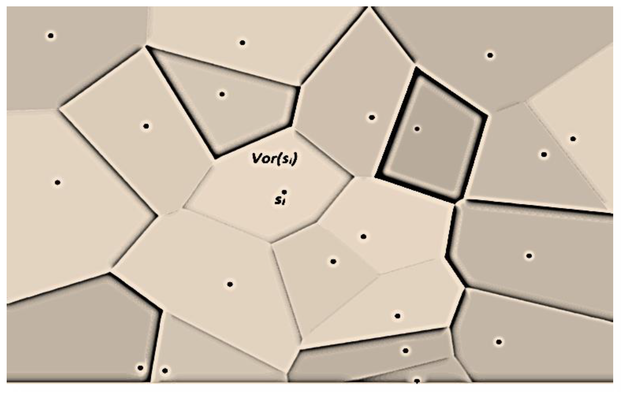
S is not practically viable. To address this challenge, we employ VD for segmenting the sensing field
S into adjacent convex polygons, called cells, denoted as Vor(
s1), Vor(
s2), ….., Vor(
sn). Each cell Vor(
si) is connected to only one sensor
si, with
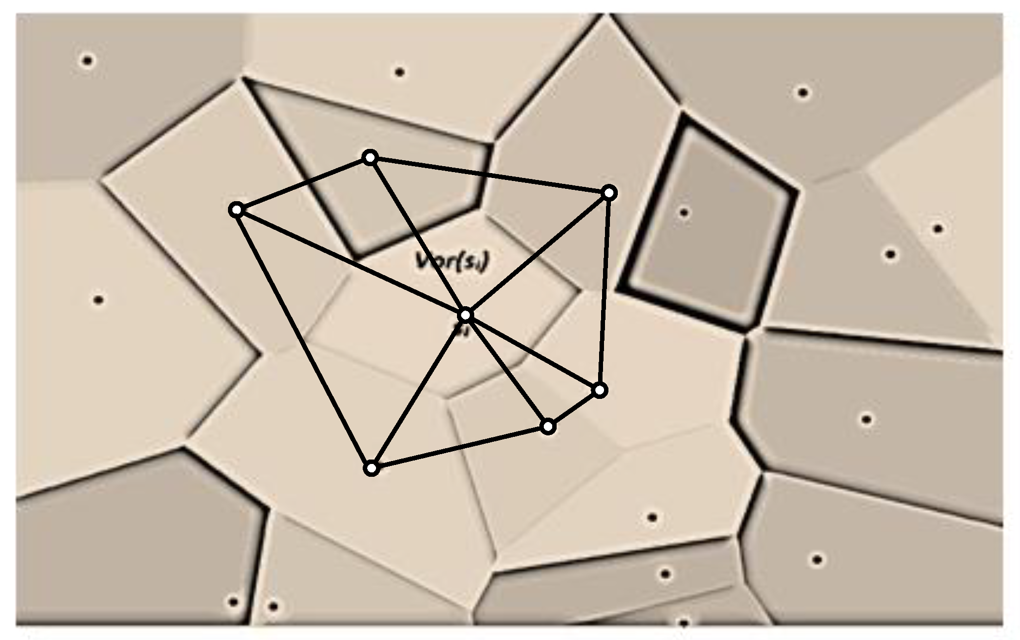
, as illustrated in
Figure 8.
The perpendicular bisector of the line segment linking sensors
and
splits the plane into two half-planes. Let
denote the half-plane that contains
, while
denotes the half-plane that contains
. Note that a point
if and only if
. Thus, Vor(
) is the intersection of all half-planes generated by the perpendicular bisectors of the line segments of
and each sensor in its neighborhood, i.e.,
. Each bisector line segment is called an edge, and the endpoints of this edge are called vertices. For any point
in
,
is the closest sensor to
p. Note that if
p is on a common edge of two neighboring polygons, then it is equidistant from the two sensors associated with these polygons [
1].
The following lemma provides the necessary and sufficient conditions to have full coverage in VD.
Lemma 1 ([
1])
. Sensing field S is fully covered if and only if all vertices in its corresponding Voronoi diagram have a distance less or equal to to at least one of their associated sensors, . The coverage problem of sensing field
S is now converted, by Lemma 1, from checking a non-finite set of points in
S into testing a finite set (The size of this set is at most 2n − 5 [
18]) of points representing the cell’s VD vertices. This lowers the computational cost, adding to the feasibility of the solution. If
is maintained, the full coverage of
S is guaranteed. Thus, VD is a powerful tool to show the existence of coverage holes in WSNs. However, VD is unable to quantify the area size of coverage holes. This is due to the fact that Voronoi polygons have different convex shapes with various numbers of edges and have a non-unit-circular model. Therefore, VD does not provide much information about the location and the size of each coverage hole in the field.
Therefore, a more effective structure is required to manage and monitor the borderlines of individual coverage gaps. To accomplish this objective, it becomes essential to convert each VD cell into elemental structures that facilitate local and precise tracking of such coverage holes. This transformation entails triangulating Voronoi cells such that sensor vertices configure generated triangles. The edge of a triangle,
, is formed if Vor(
) and Vor(
) have a Voronoi edge
e in common, perpendicular to
e and bisected by
e. This process generates DT, which produces angle-optimal planar triangles such that the circle that circumscribes any triangle, with non-collinear sensors, is devoid of any other sensors. It is noteworthy that the convexity property of VD persists in DT, as each triangle constitutes a basic convex polygon.
Figure 9 demonstrates various Voronoi cell triangulations. Subsequently, we present a corollary linking the coverage problem to DT’s edges.
Corollary 1 ([
1])
. If a sensing field is fully covered, the distance of each edge, , within the triangles does not exceed . Considering the Delaunay triangulation of sensing field S, let and be two triangle vertices that have sensing ranges and , respectively, then the following lemma holds.
Lemma 2. Let ∆ be a Delaunay (acute) triangle with vertices , , and , and let be a radius of the circle that circumscribes ∆. ∆ is fully covered if and only if the following formula holds. Proof. Assume that ∆ is completely covered. The circle with radius
that circumscribes ∆ has a center denoted by
c, which represents the farthest point from vertices
,
, and
. The distance between any of these three vertices and
c equals to
r. Each of the sensor vertices will contribute to covering the intra-triangle of ∆. This contribution depends on the sensing range of each sensor vertex.
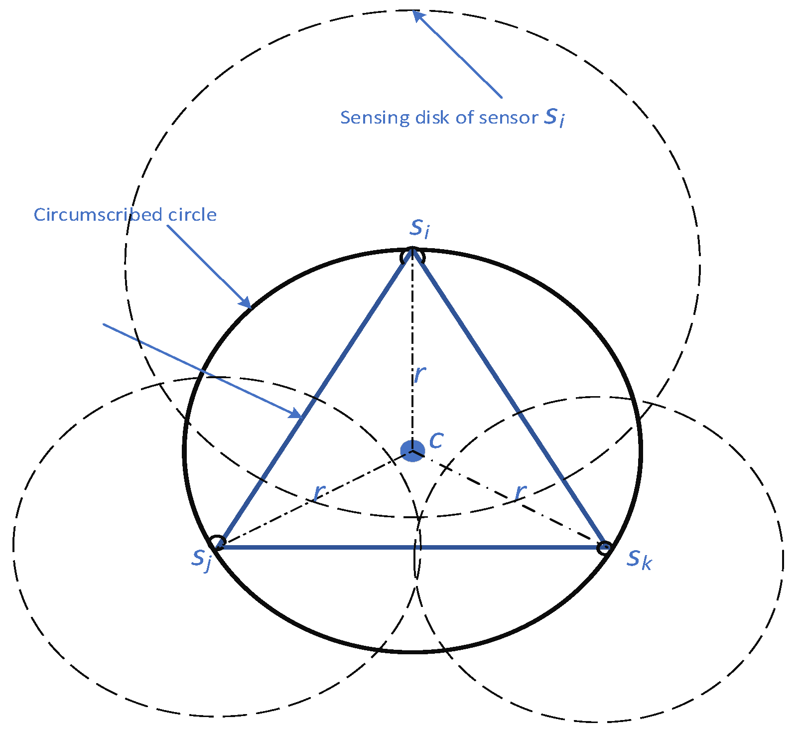
Figure 10 illustrates the concept of sensing and intra-triangle coverage. Since ∆ is covered, then every point within ∆ including
c is covered as well. Since ∆ is fully covered, the sum of contributions of the three sensors must cover the entire intra-triangle of ∆. This is formulated as follows:
where
denotes the contribution of sensor
in covering the area of triangle
. This contribution represents a sector area with a radius
.
For acute triangulation,
.
, where
is
side length. Consequently, (7) can be written as follows:
This completes the proof of the “if” part.
To prove the (only if) part, assume Formula (6) is held. Let us prove the full coverage of ∆ by contradiction. Assume that ∆ is not fully covered. Consequently, there exists a point
in ∆ that is not covered by any sensor, i.e.,
,
, where
. This means
□
In the case of homogeneous sensors, we derive the following corollary about a lower bound for sensing coverage.
Corollary 2. In the domain of cooperative sensing, utilizing a network of homogeneous sensors with a sensing range , full coverage is effectively achieved when the following formula holds.
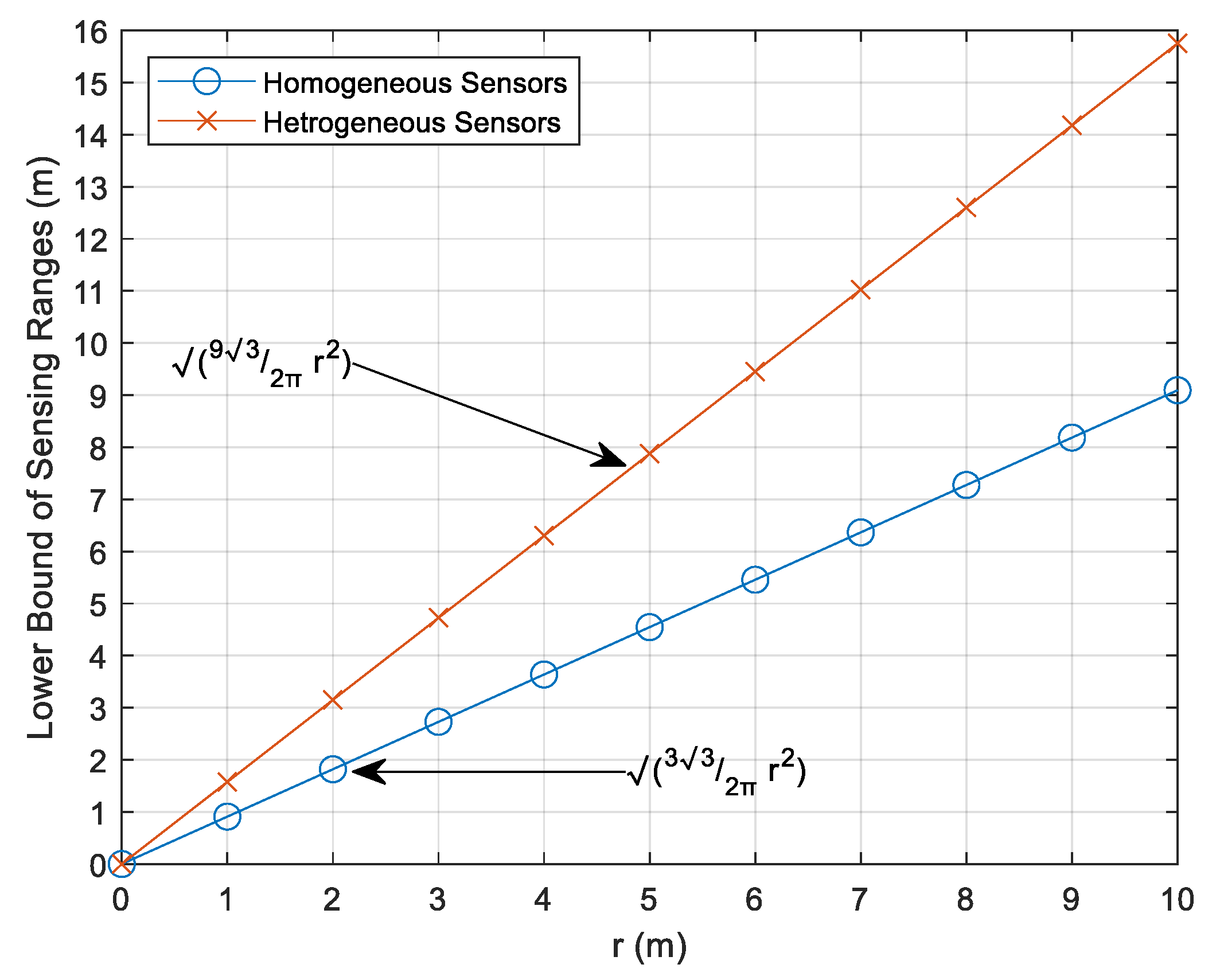
As depicted in
Figure 11, the minimum sensing ranges for both homogeneous and heterogeneous sensor types to attain full sensing coverage within triangular region ∆ are illustrated. For instance, homogeneous sensors necessitate a sensing range of no less than
, which effectively guarantees full sensing coverage, as shown by the circle-marked blue curve. Conversely, to accomplish full sensing coverage with heterogeneous sensors, the square root of the left-hand side of Equation (10) must adhere to the boundary defined by the red curve.
Next, we investigate how to detect and define the bounds of each uncovered area in DT.
4. Intra-Triangle Coverage: Beyond Ideality
By employing DT, the coverage issue is systematically converted into an analysis of individual triangle coverage within the comprehensive triangulation. Lemma 2 asserts that a failure to satisfy its condition results in an uncovered area within the circumcircle of ∆. With respect to the maximum angle θ in ∆, we can distinguish three distinct circumcenter scenarios: residing within ∆ when , outside ∆ when , or on the longest side opposite to . Despite DT offering superior optimal-angle planar triangles (angles approximating π/3), random deployment scenarios may yield angles larger than π/3. This gives rise to the following question: What constitutes the minimum sensor density for well-behaved DT?
Consider
as the minimum sensing range among all IoT sensors present within target field S. Under optimal conditions, all angles of ∆ equate to π/3 (forming an equilateral triangle) with the triangle’s side length represented by
[
19]. Consequently, the triangle’s area in this instance is
. Additionally, any triangulation includes 2
N – 2
− triangles, with
N representing sensor quantity and
β indicating sensors located along the convex hull boundary of field
S [
20]. Assuming sensing field
S exhibits dimensions
L ×
L, each triangle must cover an area size of
. Thus, we deduce the following equation:
We assume that the minimum density is achieved. As demonstrated in the proof of Lemma 2, the coverage contribution of a sensor
corresponds to the size of the angular sector centered at
with radius
. Calculating the contribution of
in ∆ requires the angle at
as shown in (8). Since the lengths of all edges of ∆ are known, we use the cosine formula to extract the angle at each sensor.
where
a,
b, and
c are the lengths of ∆’s sides, and
is the angle opposite to the side of length
c. Therefore,
is plugged into (8) to get
, where
is the angle at
in a triangle ∆. The following formula gives the intra-triangle coverage of ∆, denoted by
.
where
,
V(∆) is the set of the three vertices of ∆, and
is the common area size contributed by both angular sectors centered, respectively, at vertices
and
, and
is the area covered by all three vertices.
Next, we incorporate our intra-triangle coverage examination to detect coverage gaps within a target sensing field.
5. A Deeper Look at the Effect of Anchor Misplacement on Sensing Coverage
We revisit the concept that anchor misplacement results in two distinct types of coverage gaps: inaccurately perceived and hidden, unreported true coverage holes. To tackle these emerging coverage gaps near the sensor nodes affected by anchor misplacement (i.e., localized using misplaced anchor nodes), we employ our analysis from the preceding section. Let represent the set of impacted sensor nodes. Furthermore, let denote the actual sensing coverage area encompassed by sensor node . We now present several crucial auxiliary definitions.
Definition 2. The collective actual sensing coverage () of all affected sensor nodes in WSN is defined as a union of their physical sensing coverage in the target field. That is, .
Let be the erroneous estimated location of . will report sensed data from an inaccurate location, creating a perceived coverage around . Further, let denote the perceived sensing coverage area that is covered by the affected sensor node as if is in coordinates.
Definition 3. The collective perceived sensing coverage () of all affected sensor nodes in WSN is defined as follows. .
In order to analyze and distinguish between
and
, as well as to identify the scenarios resulting in different types of coverage holes, we employ DT in examining the problem within the vicinity of each impacted sensor node. We utilize a distributed algorithm, as described in [
21], to construct the DT representing the targeted sensing field
S. Lemma 2 offers a suitable criterion for demonstrating the presence of coverage holes. Based on the evaluation presented in
Section 4, subtracting
from ∆’s full area size reveals the unmonitored region within ∆ as follows:
where
refers to the area size of ∆ and is given by the following equation.
, where and a, b, and c are the length of the sides of ∆.
Assume
is a sensor node affected by anchor misplacement, with its incorrect estimated location represented by
, having coordinates (
). Let
be the corresponding localization error vector. The adjusted coordinates for
s position are
.
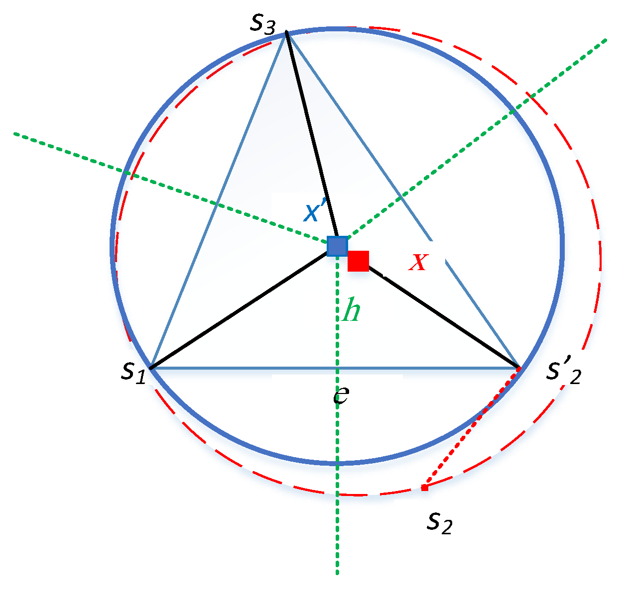
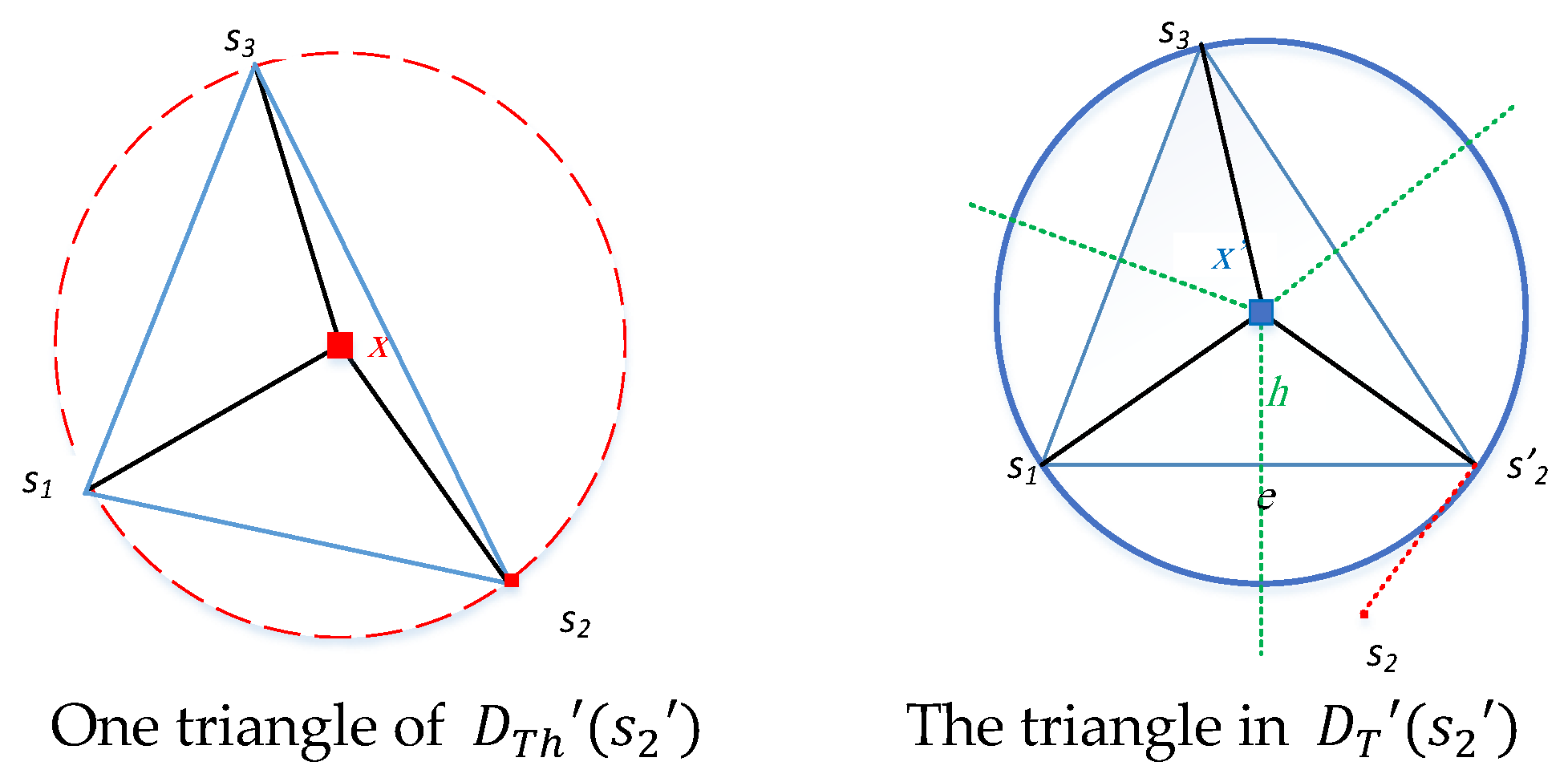
Figure 12 illustrates the structural modification of the Delaunay triangle due to anchor misplacement’s influence on localizing sensor
.
To evaluate the impact of anchor misplacement on sensing coverage gaps, we must assess the sensing coverage under two different scenarios: in the presence and absence of anchor misplacement. Specifically, for each sensor node
affected by anchor misplacement, we determine the coverage gap by contrasting the sensing coverage of
and its neighboring nodes with that of
and its surrounding nodes. This enables us to compare
and
in their vicinities.
Figure 5 and
Figure 6 show the vicinity of affected sensor
(i.e.,
) and the vicinity of
(i.e.,
). The triangulation process within these vicinities allows us to examine the uncovered areas in each triangle.
Next, we employ the notion of history in graph theory to illustrate our analysis further and compute the sensing coverage for every affected sensor node in both scenarios: when anchor misplacement is present and when it is absent.
5.1. Anchor Misplacement as a Graph Operator
Let be a Delaunay Triangulation of IoT sensors in the target field with no anchor misplacement. Such misplacement triggers alterations in , subsequently influencing the localization accuracy pertaining to sensor nodes. The change in can manifest in either the length metric of the edges or modifications in the structure, as certain sensors establish or extinguish connections based on their erroneous locations. Let denote the new triangulation after anchor misplacement.
Consequently, anchor misplacement functions as a graph operator capable of mapping an input-provided graph (i.e., ) onto a distinct graph, . For an impacted sensor , its counterpart signifies accurate localization prior to anchor misplacement. However, erroneous localization post-anchor misplacement would classify it as . Thus, from a geolocation standpoint, and can be perceived as distinct sensors.
Given
, denote the set of all triangles within
induced by s
and its neighbors, i.e.,
. Analogously,
represents the set of all triangles in
induced by
and its neighbors. For instance, the triangulation process of
includes all triangles in
induced by
and its proximate nodes, denoted as
in
Figure 5 and
Figure 6. Consequently, we term
the graph history of
due to its preceding graph state prior to anchor displacement. This notation is represented as
. The notion of graph history has been previously explored in various graph theory domains, such as characterizing the asymptotic behavior of iterated line and path graphs [
22,
23].
Clearly, the subgraphs
and their history counterpart,
, may exhibit dissimilarities. Indeed, the inaccurate localization of sensors results in the presence of certain vertices in
but not in
, or vice versa. The precise positioning of each sensor within the target field serves as a crucial aspect of our investigation, as both subgraphs
and
could be isomorphic but yet display variations concerning edge lengths. Two graphs are isomorphic if they contain the same objects (i.e., vertices) linked in the same way. A demonstration of this observation can be found in
Figure 13, which depicts one triangle of
alongside its graph history,
.
To construct
from
, we proceed as follows: Firstly, identify the misplaced anchor nodes. Subsequently, eliminate the impacted sensor nodes
, along with their associated edges, and reintroduce them in their accurate positions. Ultimately, form the triangulation within their vicinity. The average number of neighbors for
, denoted as
, does not surpass six; thus, the average quantity of triangles in both subgraphs
and
remains below six [
20]. These findings show the minimal computational cost entailed by our methodology.
5.2. Identifying Coverage Holes under Anchor Misplacement
In this subsection, we detect/delineate the inaccurately perceived and hidden unreported coverage holes. To accomplish this, we focus on the mutual triangles present in both and . An empty intersection signifies that corresponds to an entirely novel structure, with none of the elements belonging to . This scenario arises when anchor misplacement results in an extremely inaccurate location for sensor , causing the estimated position to fall outside of ’s proximity. We recognize the subsequent classifications of a potential shared triangle ∆ existing between and :
Full local coverage of ∆ is maintained in both and ;
Full local coverage of ∆ exists in , but not in . This is the case of false perceived coverage hole;
There is no full coverage in both and ;
The full local coverage of ∆ exists in
, but not in
. This is the case of hidden actual unreported coverage holes as shown in
Figure 14.
Categories 1 and 3 deal with extreme cases where the triangle ∆ is either covered in both and its history or not.
Our primary objective involves detection, identification, and quantification of coverage gaps corresponding to categories 2 and 4. In
Section 3, we present a comprehensive analysis that effectively detects such coverage anomalies. Subsequently, we introduce an intra-triangle coverage technique in
Section 4, which serves as an effective tool for estimating the magnitude of the coverage hole. Leveraging the concept of history delineated in
Section 5.1, we identify the type of coverage gap. We then proceed to compute the proportionality between perceived sensing coverage,
, to the actual sensing coverage,
. This coverage ratio is designated as CRC1-CRC4 for categories 1–4, respectively.
In the context of graph G, denotes the area of triangle ∆, while signifies the magnitude of uncovered space within ∆, as per Equation (15). It is crucial to recognize that if the ratio does not equal 1 for both categories 1 and 3, inaccuracies in sensing reporting from ∆ sensor nodes may occur. Under such circumstances, the actual coverage in the history graph could be either overestimated or underestimated.
The methodology remains applicable even when multiple sensors within triangle ∆ are impacted. Let us consider and as two affected sensors and neighbors in . Redundancy in calculations arises due to shared triangles by and , leading to being computed twice since both and are affected. Consequently, it is necessary to adjust the overall ITC value accordingly within both and .
The coverage ratio expressed in Equation (16) is straightforward. By applying it to intra-triangle scenarios, we can identify varying coverage hole types caused by anchor misplacement and compute their respective percentages. Subsequently, our resilience framework enables detection of misplaced anchors and determination of impacted sensor node sets.
5.3. Calculating Lower and Upper Bounds of Coverage Holes
The intra-triangle coverage gap zones, or uncovered regions, exhibit varying geometric shapes. Nonetheless, we choose to represent the lower and upper boundaries of each uncovered region within a triangular area ∆ via circular models. The lower boundary circle is defined as a circle with its center at the polygon’s centroid, which exclusively encompasses the uncovered region in ∆ and serves as the largest circle inscribed within this space. Conversely, the upper boundary circle pertains to the smallest circumscribing circle that completely surrounds the uncovered region of ∆. To calculate the lower and upper boundaries for ∆’s uncovered region, we employ the subsequent methodology: initially, we find a set
consisting of intersection points—those situated between angular sectors and ∆’s perimeters, along with any intersection points existing among angular sectors themselves. Let
and
be two vertices in ∆. If
, we dismiss intersection points located between circles centered at
and
and the edge
. Let
represent the revised set comprising intersection points. The points contained in
formulate a polygon
. Our objective lies in determining the minimal/maximal circle that circumscribes/inscribes polygon
. To accomplish this, it is imperative to pinpoint centroid
c of this specific polygon with coordinates derived from the following formula [
24].
where
A is the area and is given by
, and
and
are two consecutive points on
s hull. Let
. The circle centered at c with radius
represents a lower bound of the uncovered area in ∆. Likewise, let
. Then
represents the size of the minimum circle that circumscribes
and, thus, serves as an upper limit for the uncovered area within ∆.
Both bounding circles are centered at the centroid of a polygon
encompassing the uncovered area. Utilizing centroid
c, as opposed to the circumcenter of Δ, proves more efficient for these reasons: (1) IoT sensor range variability causes the circumcenter of Δ to not always belong to the uncovered area. (2) If the circumcenter resides outside Δ, intra-triangle coverage calculations become irrelevant. (3) Centroid
c-based bounds offer tighter representation as they more accurately represent the uncovered area. Deriving from our analysis, below is a summary of steps for calculating lower and upper bounds within this advanced Algorithm 1.
| Algorithm 1 [1]: Lower and Upper Bounds (LUB) |
Input: triangle ∆
Output: c, lowerBound, upperBound
If HasCoverageHole (∆) then
P = findPolygon (∆);
c = findCentroid (P);
Rl = findRadiusLowerBound (P, c);
Ru = findRadiusUpperBound (P, c);
;
;
return c, lowerBound, upperBound;
End if |
In the LUB algorithm, it is assumed that every sensor has been localized and their positions are identified. During the construction of DT, each sensor recognizes its adjacent neighbors in every triangle ∆ present in DT. The LUB algorithm commences by verifying the presence of a coverage hole through the HasCoverageHole (∆) function, which evaluates ∆ against the coverage criteria detailed in Lemma 2. Upon identifying a coverage hole, the findPolygon (∆) function comes into action to find the polygon that strictly circumscribed the uncovered. The findCentroid (P) method employs Equations (17) and (18) to determine P’s centroid. The subsequent step involves calling the findRaduisLowerBound (P, c) function to compute the shortest distance between P’s vertices and c, signifying the radius of the lower bound. In a similar manner, findRaduisUpperBound (P, c) yields the greatest distance between P’s vertices and c.
6. Resiliency Approach for Misplaced Anchors
In this Section, we propose a distributed scheme that takes input from affected sensors during the validation process, and outputs the set of misplaced anchors.
6.1. The Proposed Scheme
The proposed methodology focuses on establishing the accuracy of localization and subsequently, the validity of sensing coverage by pinpointing misplaced anchors via their impacted sensors. This approach is carried out through a two-phase process:
Phase 1 (detection of affected sensors) involves each node calculating its distance to all other nodes through two methods: (a) Euclidean distance, and (b) using received signal strength (RSS). Denote
and
as the distance between nodes
and
utilizing Euclidean distance and RSS, respectively. We introduce
as the distortion vector between
, and
for node
in relation to all other nodes
as illustrated below.
where
. It is clear that the total number of vectors corresponds to a multiple of the sensor nodes count. In order to calculate the average two-way distances, which include
,
,
, and
, an extensive computational effort is necessary. This leads to increased latency in identifying misplaced anchors. To address this challenge, we investigate two scenarios:
(1) Computation of a single vector originating from one sensor to all other sensors. For enhanced efficiency, we strategically select a sensor node situated near the target field’s center;
(2) Calculation of multiple vectors followed by obtaining the average for two-way distances.
Regardless of the case employed, Phase 1 will yield a single vector output. Subsequently, we arrange this vector in descending order based on distortion levels from high to low. Employing the K-means algorithm with K = 2 clusters, we classify the vector elements into two distinct categories: sensors with relative accuracy and those affected by misplaced anchors.
In
Phase 2 (determining misplaced anchors), the objective is to leverage the outcomes of the K-means algorithm from the prior phase to pinpoint misplaced anchor sets. Among the two produced classes, the one exhibiting a high mean localization error signifies impacted sensors. As a result, misplaced anchors reside within those that have localized the affected sensors. To establish the misplaced anchor set, let
represent a collection of anchors involved in localizing sensor node
via the trilateration technique. Additionally, let
be a subset of relatively precise sensor node locations. We delineate benign anchors,
, as a collective set of anchor nodes participating in localizing all relatively accurate sensors as follows.
Consequently, the misplaced anchors, , belong to the complement set as follows. . It is crucial to recognize that and are not necessarily mutually exclusive. In fact, these misplaced anchors may contribute to the localization of certain sensors, even though the K-means algorithm deems their positions relatively accurate. Next, we enhance the detection scheme to address this particular aspect.
6.2. Enhanced Detection Scheme
The earlier proposed methodology had the potential to yield an increased rate of false alarms regarding incorrectly positioned anchors. To address this issue, we propose the subsequent refinement process. Firstly, we organize the category/cluster of relatively precise sensors, arranged in descending order according to their localization inaccuracies. Next, we examine each sensor within the sorted group individually.
Considering
as the sensor with the most significant localization error amidst others in the ordered category, we look into
,
, and
—the anchors responsible for localizing
. We then assess these three anchors based on specific criteria: should any of these anchors be nearer to the influenced group’s centroid rather than that of the relatively precise sensors cluster, and exhibit a distortion greater than a particular threshold compared to a benign anchor, it is then reclassified as
. This threshold depends on historical information accounting for SNR. In evaluating an anchor,
, we employ a technique similar to our earlier discussion concerning distortions between Euclidean and RSS-based distances as highlighted below:
where
denotes a benign anchor. We continue repeating the second step as long as there is at least one anchor participating in localizing sensor
that fulfills the specified criteria. To guarantee this procedure’s efficiency, we select
from among benign anchors that have contributed to localizing high-accurate sensors.
7. Numerical Results and Discussion
7.1. Simulation Results
In this section, we rigorously evaluate our resiliency methodology and demonstrate its effectiveness. Our analysis involves experimental trials on both a homogeneous and a heterogeneous network, leveraging the devised framework to assess network dependability. The aggregate of simulation outcomes is achieved by iteratively performing the experiments and computing the mean values from the distinct results. This specific figure correlates to result convergence and fluctuation. For instance, if the outcomes reach stability and exhibit minimal variability after x iterations, then we embrace x (or a value exceeding x) as an optimal number of repetitions.
7.2. Validation
Initially, we demonstrate the effectiveness of our technique by identifying the impacted sensors and subsequently the misplaced anchors. Our goal is to categorize these two sensor groups utilizing the K-means clustering algorithm. We implement this in the experimental environment illustrated in
Figure 2. Upon executing Phase 1 of our method,
Figure 15 emerges, presenting the groups of affected and relatively unaffected sensors alongside their centroids. Most affected sensors are accurately integrated into group 1, showcasing our approach’s technical proficiency.
We validate our approach by running an enhanced version of Phase 2. We have calculated the localization errors for different trials (1, 2, 7, 11, 16, 20, 27, 40) and found that the results converge after 16 trials. Measuring the variance of localization errors suggests that 20 iterations are enough to provide convergent and stable results. Thus, each experiment is repeated 20 times for any given network topology. We take a random sample of 15 observations of averaged localization error values generated by the two anchor groups per iteration. To analyze the statistical significance of the difference between the localization errors generated by the two anchor classes, we adopt the following hypotheses:
Null hypothesis : μ = 0, which means the true difference of means for the corresponding anchor groups is equal to zero;
Alternative hypothesis : μ ≠ 0.
We employ a confidence interval of 95%, which is equivalent to a significance level of α = 0.05. If the p-value is less than or equal to α, we discard the null hypothesis. This rejection conveys that there is a statistically significant difference between the localization errors induced by the two anchor classes, thus favoring the alternative hypothesis. In this case, the confidence interval does not contain zero.
According to our analysis, with a p-value as low as 1.9551 × 10⁻⁴, we can confidently reject the null hypothesis as it validates significant differences in mean values between anchor classes. The lower and upper limits of confidence intervals for mean differences fall between −4.505 and −3.4446, further supporting this conclusion.
Our results show a validation of our approach in identifying misplaced anchors with a confidence level of 95%.
7.3. Verify the Effectiveness
We demonstrate our framework’s resilience against unreliable nodes in this section. By effectively mitigating the impact of misplaced anchors on IoT nodes, we aim to minimize their involvement in the localization process. We employ the NS-3 simulator to model various experimental scenarios featuring randomly dispersed, non-uniform IoT sensors across the target field. These experiments intend to show our framework’s efficacy. Additionally, we utilize a distributed algorithm outlined in [
21] to construct a DT that accurately represents the target sensing field. A comprehensive overview of the simulation settings can be found in
Table 2.
- (1)
The Effectiveness of Localization and Perceived Coverage
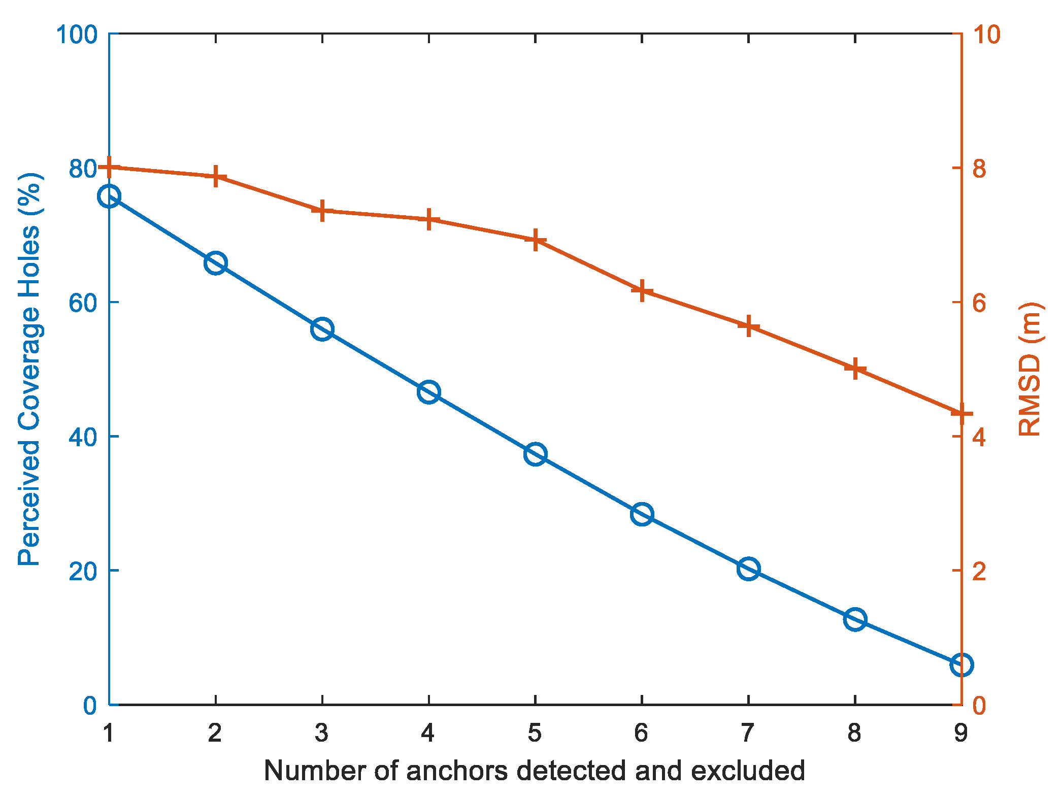
The objective of this cutting-edge experiment is to investigate the influence on Root Mean Square Distance (RMSD) and the perception of coverage gaps as the proposed framework identifies and discards an increasing number of misplaced anchors. We employ RMSD as a performance metric to quantify the localization inaccuracies present in the network.
where
and
, respectively, are the actual and estimated positions of sensor node
and
is the total number of sensor nodes.
As illustrated in
Figure 16, our framework demonstrates an effective ability to reduce both the RMSD and the percentage of perceived coverage gaps as the count of identified anchor nodes increases. The perceived coverage reduction exhibits a sharper decline when compared to RMSD, attributable to its direct correlation with the number of misplaced anchors within the network. Conversely, RMSD is primarily influenced by multiple factors, such as sufficient reliable anchor nodes per sensor and the SNR impact on distance measurement quality.
- (2)
The Effectiveness of Perceived Coverage Holes for Different Sensing Range Values
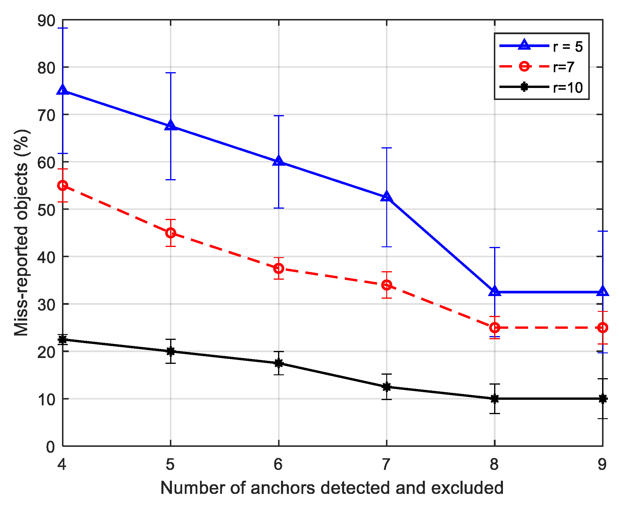
In order to demonstrate the efficacy of our novel approach when applied to a heterogeneous network consisting of varying sensing range values, we conducted simulations using the following scenario: 40 distinct objects within a terrain, such as gas pipelines. Sensor nodes have been strategically placed to ensure comprehensive monitoring for gas leaks throughout all pipes. Our study assumes that anchor-based localization is utilized for sensor positioning. In cases where anchor misplacement occurs, we aim to highlight the influence of our proposed method on the percentage of misreported objects. How significantly does our proposed framework contribute to mitigating false coverage perception as an increasing number of misplaced anchors are identified and eliminated from network services? The findings of this investigation are presented in
Figure 17.
The 95% confidence interval reveals that the proportion of misreported objects within the three curves becomes statistically negligible as an increasing number of misplaced anchor nodes are identified and removed. This occurs due to the fact that, irrespective of the sensing range, the elimination of more misplaced anchors leads to an enhanced validity in sensing reports and subsequently a decrease in misreported objects. Our findings indicate that employing a smaller number of sensing nodes with larger sensing ranges results in a more rapid recovery from anchor misplacements. In essence, the proposed framework considerably reduces the number of misreported objects as the sensing range expands, showcasing its technical efficiency.
- (3)
The Effectiveness of Perceived Coverage Holes for Different SNR Values
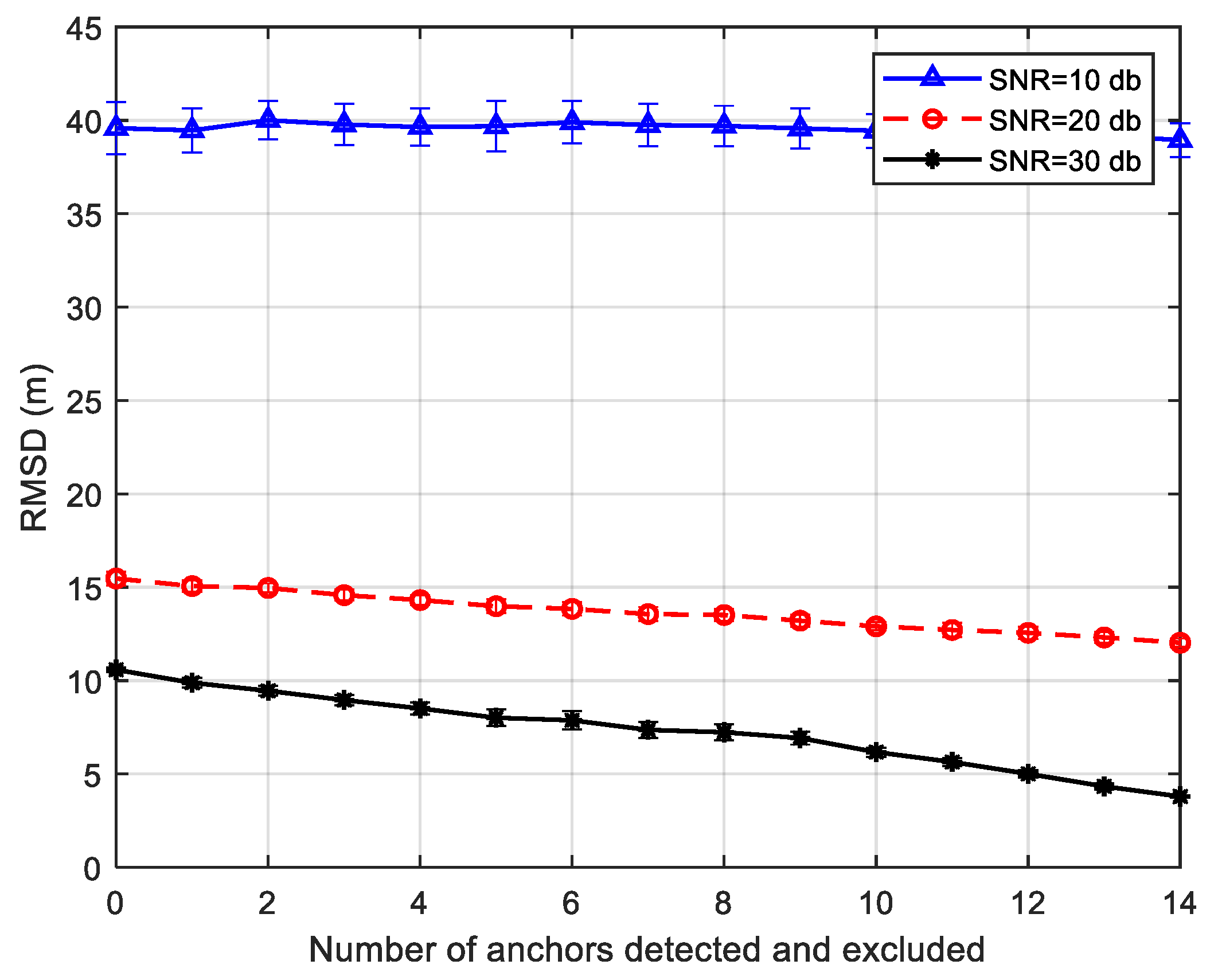
Through a series of experiments, we effectively show the high capabilities of our novel framework at varying SNR levels, namely 10, 20, and 30 dB. The primary objective is to evaluate the influence of anchor misplacement and measurement inaccuracies on localization precision. As depicted in
Figure 18, our cutting-edge framework exhibits superior performance with higher SNR levels. This performance can be explained as follows: as the SNR values decrease, the measurement errors escalate due to weakened signals, undermining the reliability of the localization system. Interestingly, for an SNR of 10 dB, the RMSD remains relatively stable—excluding additional misplaced anchors does not affect the RMSD. Furthermore, the application of a 95% confidence interval unveils the statistical significance of RMSD values for diverse SNR trajectories, thus highlighting the crucial role that reduced SNR values play in determining sensing dependability.
8. Conclusions
In this paper, we proposed a novel resilience framework for detecting anchor misplacement, identifying coverage holes/gaps, and accurately measuring their dimensions. To achieve this, we performed a comprehensive computational geometry-based examination of the targeted sensing field, taking into account various error components, particularly anchor misplacement. By implementing Voronoi Diagrams (VD) and Delaunay Triangulation (DT), we strategically divided the sensing field to effectively evaluate coverage deficiencies. Utilizing VD and DT allowed us to address the coverage gap issue with a minimal number of points within the target sensing field, subsequently reducing computational expenses and enhancing the feasibility of our approach in IoT environments.
We then evaluated intra-triangle coverage, revealing novel categories of coverage holes: actual unreported and perceived coverage holes. The experimental results demonstrated the validity and efficiency of our proposed resilience framework in attaining localization precision and sensing coverage while bolstering overall IoT-based system dependability. These findings provide valuable insights for cooperative and overlapping IoT systems to optimize resource allocation by either tolerating coverage loss or deploying supplementary sensors to fill the coverage holes.
As future work, we aim to develop a cutting-edge framework that prolongs the lifespan of IoT networks through collaborative sensing and leveraging the intra-triangle analytics provided in this research. For instance, overlapping sensors from multiple network operators could devise an intelligent sleep mode schedule based on each sensor’s role. Additionally, mobile sensors may serve as backup support for low-energy sensors while covering actual unreported sensing gaps.
