Article

Performance Enhancement of CAN/Ethernet Automotive Gateway with a CAN Data Reduction Algorithm

1
Department of Electrical and Computer Engineering, Sungkyunkwan University, Suwon 16419, Republic of Korea
2
Department of Computer Engineering, Kyungnam University, Changwon 51767, Republic of Korea
*
Author to whom correspondence should be addressed.
Electronics 2023, 12(13), 2777; https://doi.org/10.3390/electronics12132777
Submission received: 29 May 2023 / Revised: 21 June 2023 / Accepted: 21 June 2023 / Published: 22 June 2023
(This article belongs to the Special Issue Ubiquitous Sensor Networks II)

Abstract

:
Data reduction (DR) techniques for the controller area network (CAN) are being developed to reduce the increased bus load caused by the growing number of electronic control units (ECUs) and automotive software complexity in modern automobiles. DR techniques enable the transmission of the same information with less bandwidth, effectively reducing the busload in CAN-based networks. Modern vehicles are composed of various in-vehicle network (IVN) protocols, such as CAN, local interconnect network (LIN), and Ethernet. However, existing DR techniques only consider the communication between CAN nodes. The application of DR techniques to a CAN bus may lead to compatibility issues when communicating with heterogeneous IVN protocols. This paper proposed a CAN/Ethernet gateway system for seamless communication with CAN DR. The proposed gateway system was implemented on a TC275-based embedded system, and its performance was evaluated and analyzed. The experimental results revealed that CAN DR compression effectively improves both the CAN bus load and end-to-end processing time of the gateway system. The CAN bus load was reduced by up to 33.68%, and the average end-to-end processing time was reduced to 336 μs.

1. Introduction

Electronic control units (ECUs) enable a wide range of features and requirements in modern vehicles. As a result, the number of ECUs in automobiles continuously grew to implement advanced functionality and meet safety standards. Some contemporary automobiles may have as many as 150 ECUs connected through various in-vehicle network (IVN) protocols, including the Controller Area Network (CAN), local interconnect network (LIN), FlexRay, and Ethernet [1]. As the number of ECUs in vehicles continues to rise, the associated data traffic on in-vehicle networks is increasing. The CAN is the dominant protocol for IVNs; however, its bandwidth is limited to 1 Mbps. This limitation can lead to CAN bus overload when data traffic is high, causing low-priority messages to experience increased latency and potentially miss deadlines [2]. Consequently, estimating the worst-case response times can be challenging, which can lead to critical issues in automotive networks.
The use of higher-bandwidth network protocols or the design of multi-bus networks are potential solutions for reducing bus loads. However, implementing these solutions requires significant changes to existing automotive network systems, potentially resulting in increased costs and reliability issues [3,4]. Another approach to address the increased data traffic on the CAN bus is the implementation of the CAN data reduction (DR) technique, also known as data compression. The basic concept of the DR is to transmit only the differences between the previous and current data instead of all data, as successive CAN data typically do not change frequently [5]. This reduction in transmitted data helps alleviate the load on the CAN bus. Compared to other solutions, the DR offers a cost advantage, as it can be implemented through software updates without requiring hardware changes [6].
Contemporary vehicles use various IVN protocols, and communication between these different protocols is essential [7,8,9]. However, existing CAN DR techniques primarily focus on the communication between CAN nodes, necessitating additional implementations to enable seamless communication with networks using other protocols. The implementation of CAN DR on all nodes using other protocols is inefficient. The implementation of CAN DR in the gateway system can solve this problem. The gateway system allows a CAN with DR to communicate with other protocols while using the DR technique. Additionally, the gateway system typically possesses higher computing power compared to normal ECUs, allowing for faster execution of compression and decompression processes.
This paper builds upon our work presented in [10] and extends the scope beyond merely measuring the compression efficiency of CAN DR algorithms. Its primary objective was to evaluate the impact of CAN DR in an automotive network with heterogeneous IVN protocols. To achieve this, the paper conducted comprehensive measurements and assessments of (de-)compression processing time at the gateway system, CAN message delay times, and CAN/Ethernet end-to-end processing times. The experimental results presented in this paper demonstrate the advantages of utilizing CAN DR in a vehicle network environment with multiple IVN protocols.
The rest of this paper is structured as follows: Section 2 provides a brief overview of related work. Section 3 describes the implementation of the gateway system. In Section 4, we present the experimental setup and discuss the results. Finally, Section 5 concludes the paper, summarizing and suggesting future research directions.

2. Related Work

2.1. Gateway

The IVN architecture of modern vehicles employs heterogeneous protocols such as CAN, LIN, FlexRay, and Ethernet, each with distinct characteristics. A gateway is required to enable seamless communication among multiple networks using various protocols [9,11,12,13,14,15,16,17,18,19,20]. The automotive electric/electronic (E/E) architecture is undergoing a transition from a central gateway to a domain E/E architecture [11,19]. In the central gateway E/E architecture, the entire IVN is connected to a central gateway that provides data exchange between the heterogeneous network protocols. In the domain architecture, ECUs are categorized into various domains based on their respective functions, such as powertrain, chassis, body, and infotainment. Each domain has a high-performance server ECU called a domain controller unit (DCU), which serves as a gateway between the Ethernet backbone and its subnetwork [21]. In the domain architecture, the gateway or DCUs support communication between heterogeneous protocols or different domains.
Various automotive gateways [11,12,13,14,15,16] that use heterogeneous IVN protocols were proposed. A gateway framework for IVNs that includes CAN, FlexRay, and Ethernet was proposed in [11]. This gateway framework was designed to be easily reusable and verifiable and can be configured using graphical user interface (GUI)-based software. A gateway between FlexRay and Ethernet audio video bridging (AVB) was proposed in [12]. This paper addressed a FlexRay and Ethernet AVB synchronization mechanism, aiming to ensure a high quality of service (QoS). Another gateway between Ethernet and FlexRay was proposed in [13]. The authors in [13] considered not only the exchange of data between two protocols but also the mechanism of cybersecurity. A gateway between CAN and Ethernet was proposed in [14]. This study addressed the transformation concept between CAN-based and Ethernet–IP-based networks. Transformation variants such as buffered and timed approaches were presented. However, they did not consider CAN DR. A CAN–Ethernet gateway with graphical software for control and diagnosis was proposed in [15]. This paper proposed a method for packing and unpacking one or more CAN messages within an Ethernet frame. A gateway to support time-synchronization between CAN and Ethernet was proposed in [16]. This paper proposed a time-synchronization method based on the precision time protocol (PTP) between CAN and Ethernet networks.
A summary of the gateway in related works is shown in Table 1. Various research focused on data conversion methods between heterogeneous IVN protocols and improvements in automotive gateways. This study focused on seamless communication between a CAN bus with DR and Ethernet network.

2.2. CAN Data Reduction

CAN DR, which is also referred to as CAN data compression, is a technique aimed at reducing the volume of CAN data transmitted over a CAN bus. This technique relies on the repeatability of data bytes in consecutive messages with the same CAN ID and takes advantage of the fact that vehicle data communicated via the CAN bus are repetitive and do not change frequently [3,4,5,6]. CAN DR can achieve bus load reduction by presenting the same information with fewer data. The implementation of CAN DR requires only software development and no hardware changes. Therefore, the cost of reducing the CAN bus load is negligible.

2.2.1. Enhanced Data Reduction

The enhanced data reduction (EDR) algorithm employs a delta compression technique that uses the difference between previous and current data [3]. In the EDR algorithm, a compressed CAN message can contain two types of signals. The first type is signal, delta, no-change (SDN), which includes CAN signal with a bit length of five or more. The second type, signal, no-change (SN), includes a CAN signal with a bit length of four or fewer. The SN type signals can be grouped to represent a group of SN signals as a single SN signal.
In the EDR algorithm, the compression status of signals is denoted by the data compression code (DCC) located in the first byte of a CAN message’s data field. A DCC bit value of 0 indicates that the signal is uncompressed, while a value of 1 indicates either delta compression or fully compression. Compressed signals consist of a reduction type (RT) bit as the first bit, indicating whether the signal is delta-compressed (RT = 0) or fully compressed (RT = 1). When an SN signal is compressed, it is always fully compressed; therefore, there is no need for an RT bit to indicate delta or fully compression for the SN signal.

2.2.2. Quotient Remainder Compression

The quotient remainder compression (QRC) algorithm is similar to EDR but differs in the number of extra bits allocated per signal. As the name suggests, the QRC algorithm employs a division operation for compressing the CAN message signal [22]. The first byte of the data field in the QRC is referred to as the compression information byte (CIB), which serves the same purpose as EDR’s DCC by indicating the compression status of the signal.
In the QRC algorithm, signals are grouped into two types. G5 signals are at least five bits or greater in length. Signals grouped under this category are compressed using quotient remainder (QR) compression. During QR compression, each signal value is divided by a predefined divisor, and the result is transmitted as QR bits along with the remainder of the division. QR bits consist of 2 bits and indicate the status between the current and previous quotient values. When the QR bits are set to ‘01’, it means the current quotient value is the same as the previous value plus one. If the QR bits are set to ‘10’, it means the current quotient value is the same as the previous value minus one. When the QR bits are set to ‘00’, the current quotient value is the same as the previous quotient value. If the QR bits are set to ‘11’, the current signal value is the same as the previous signal value. In this case, only the QR bits are transmitted without the remainder. If the QR bits are not ‘11’, the receiver of the compressed message will calculate the current signal value from the quotient value obtained with the QR bits, predefined divisor, and remainder.
The L5 signals are less than five bits in length. Signals grouped under this category are not QR compressed because the overhead is greater than 60%. In comparison to the EDR, the QRC offers a wider compression range of up to double that of EDR. Additionally, the QRC achieves a compression ratio comparable to that of the EDR.

2.2.3. Boundary of Fifteen Compression

In the boundary of fifteen compression (BFC) algorithm, a CAN signal can be compressed if its current value differs within the maximum compression range (±15) compared to the previous value [2]. The BFC algorithm classifies CAN signals into two categories: boundary of fifteen (BF) signals for signals with a length of six bits or more, and non-boundary of fifteen (NBF) signals for signals with a length of five bits or less. Unlike the aforementioned CAN DR algorithms, the BFC does not utilize DCC or CIB to indicate the compression status of signal. Instead, each signal is preceded by one or two bits that indicate its compression status.
NBF signals are excluded from compression using the BFC technique since the compression results in more bits than the length of the NBF signals themselves. Each NBF signal is assigned a bit parameter compression (BPC) bit. A BPC bit value of ‘0’ indicates that the NBF signal is uncompressed and is transmitted in its entirety. On the other hand, if the BPC bit is ‘1’, it indicates that the NBF signal is fully compressed, and only the BPC bit itself is transmitted.
The BF signals are compressed using the BFC technique. The BF signal can be compressed using four methods. Each BF signal is allocated with parameter compression (PC) bits to represent the compression states. The BF signal compression status is listed in Table 2. If the PC bits are set to ‘00’, the BF signal is not compressed, and if the PC bits are set to ‘01’, the BF signal is fully compressed hence only sent PC bits.
An example of a compressed CAN message using BFC is shown in Figure 1. Sig 1~4 are BF signals. Sig 1 is not compressed, so its PC bits are set to ‘00’ and sent completely. Sig 2 is fully compressed, so its PC bits are set to ‘01’, and only PC bits are sent. Because Sig 3 and Sig 4 are compressed using the BFC technique, they are sent with a delta value to represent the change in the signal value. Sig 5 and Sig 6 are NBF signals. Sig 5 is not compressed, and so, its BPC bit is set to ‘0’ and the signal value is fully sent. Sig 6 is fully compressed; therefore, only the BPC bit is sent.
A summary of the DR algorithm in related works is shown in Table 3. In addition to these, several other DR algorithms were proposed to enhance the compression performance of CAN DR [23,24,25,26,27]. However, the current research on CAN DR algorithms lack analyses on vehicular networks with heterogeneous IVN protocols. Existing studies primarily focused on the CAN bus, disregarding the prevalent use of multiple protocols in modern vehicles. Hence, it is crucial to analysis the effectiveness and adaptability of CAN DR algorithms within vehicular networks that employ multiple protocols.
In this study, we implemented a modified DR algorithm based on the BFC algorithm in the proposed gateway system. Due to the memory limitations of the hardware used in our implementation, we prioritized code size constraints. Consequently, we chose to use the BFC algorithm due to its fixed delta size regardless of the signal size, making it easy to implement and providing efficient performance [28,29]. The description of the modified DR algorithm is presented in Section 3.2.

3. Proposed Gateway System

3.1. Gateway Implementation

3.1.1. Hardware Configuration

The implemented gateway system is shown in Figure 2. The gateway system implementation was carried out with an embedded system based on the TC275 MCU product developed by Infineon Technologies [30]. The TC275 MCU was based on the TriCore architecture and is designed for automotive and industrial applications.
The comparisons of commercial evaluation gateway board and the proposed gateway system are shown in Table 4. The two evaluation boards manufactured by Infineon support CAN, CAN FD, LIN, FlexRay, and Ethernet protocols. The S32G3-VNP-RDB3, manufactured by NXP, supports CAN, CAN FD, LIN, FlexRay, and Ethernet TSN protocols. This embedded board provided four channels for CAN, and one channel for Ethernet. The TC275 MCU included CAN and Ethernet controllers. A limitation of the embedded system used in this paper was its lower memory capacity compared to commercial gateway boards.

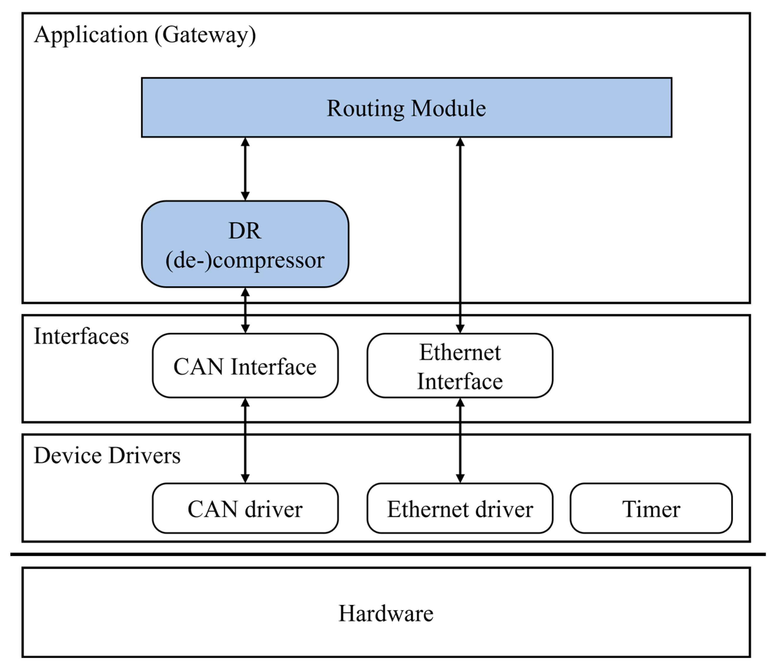
3.1.2. Software Configuration

The software architecture of the proposed gateway system was divided into three layers, as shown in Figure 3: a device driver layer, an interface layer, and gateway application layer. The device driver layer provided device drivers to control the hardware components in the hardware layer and included modules for communication, timer, and interrupts.
The interface layer served as the interface between the gateway application and device driver layer. The gateway routing module and DR (de-)compressor program, which executed the DR algorithm, were implemented in the gateway application layer. The DR compressor decompressed the CAN messages and passed them to the routing module. It also compressed outgoing CAN messages and transmitted them through the CAN interface.

3.2. Data Reduction Mechanism

In the proposed gateway system, we used a modified version of the BFC algorithm on the original BFC algorithm described earlier. In the modified BFC algorithm used in the proposed gateway system, signals with a length of six bits or more, which were identified as BF signals, were compressed using the BFC technique, as in the original BFC algorithm. A detailed description of how to compress the BF signal was already provided in Section 2.2.3 of this paper and in [2].
The modified BFC algorithm differed from the original BFC algorithm in its compression of the NBF signals. In the modified BFC algorithm, NBF signals can be grouped into an NBF signal group with a maximum size of 8 bits. Grouping was performed according to the number and size of NBF signals in each CAN message. An NBF signal group was treated as one NBF signal, such that if one NBF signal in the group changed its value, all signals in the group were transmitted uncompressed. The overhead of grouping was not significant because the frequency of value changes for CAN message signals classified as NBF signals, such as headlight, gear, and engine statuses, was relatively low.
NBF signal group compression was accomplished by comparing the values of all signals within the signal group to their respective previous values. If even one signal in a group changed compared to the previous value, the BPC bit was set to ‘0’, and all signal values in the group were transmitted. Otherwise, only the BPC bit of the group was sent. The values of the NBF signals did not change frequently. Hence, grouping the NBF signals can reduce the number of BPC bits required.
The DR compressor in the proposed gateway system performed the decompression of the signals in the compressed CAN message. The DR compressor knew the order of the signals in each compressed CAN message using the CAN ID when the message was compressed. Therefore, the DR compressor can decompress a compressed signal by reading the appropriate number of bits, without the need for any special bits to classify the signal.
For BF signals, they are decompressed using the same method as the original BFC algorithm. In the case of a group of NBF signals, if the BPC bit is ‘0’, it indicates that one or more signals in the NBF signal group have changed. Consequently, the DR compressor reads additional bits and updates the value of each signal in the group to the buffer, considering the number of signals in the group and their respective lengths. Conversely, if the BPC bit is ‘1’, no action is taken as it signifies no change in the value of the signal within the NBF group.
Although research is ongoing into security mechanisms using CAN DR compression, the proposed gateway system does not consider security mechanisms [34,35].

3.3. Routing

The proposed gateway system provides two routing methods: PDU-based and signal-based routing. A typical automotive gateway system additionally provides a frame-based routing method. In frame-based routing, a message frame received on one network is forwarded to another network with only the frame format translation [9]. Routing is performed directly between each protocol interface in the interface layer [11]. However, the DR compression and decompression are conducted by the DR compressor in the gateway application layer. We did not implement frame-based routing in our proposed gateway system because the compressed CAN messages are sent as Ethernet messages without any modifications, which may not be compatible with the receiving network’s protocol.
The proposed gateway system utilized a routing module that performed PDU and a signal-based routing process. As the proposed system used a modified version of the CAN protocol with the DR algorithm, the received CAN messages must be decompressed before routing. In contrast, when routing an Ethernet message to a CAN network, the message was translated into CAN message(s) via a router before compression was performed.
Examples of routing sequences of the CAN/Ethernet message are shown in Figure 4 and Figure 5. Both examples illustrate PDU-based routing situations. The received CAN messages were converted into decompressed CAN messages by the DR compressor. Then, the routing module copied the CAN message ID and data of each CAN message into an Ethernet message based on the ID of the received CAN message. Due to the minimum frame length of Ethernet being 64 bytes, which was longer than the size of a single CAN data field (8 bytes), it was possible to include multiple PDUs within an Ethernet message. If the transmission conditions of the Ethernet message were satisfied, the message was forwarded to the Ethernet interface. However, when the gateway system received an Ethernet message that included multiple CAN PDUs, each PDU in the Ethernet message was translated into destination CAN messages using the routing module. Each CAN message must be compressed before it is sent to the CAN bus, which was performed by the DR compressor.

4. Results and Discussion

This section describes the experiments conducted to evaluate the performance of the proposed gateway system. To evaluate compression performance, we measured the number of bytes sent for each CAN message and the CAN bus load. Additionally, we measured the end-to-end transmission latency, as well as the compression and decompression processing time, to evaluate the delay caused by adding the compression and decompression processes.

4.1. Experimental Environment

An experimental environment was designed to evaluate the performance of the gateway system using an embedded system and two VN5610 devices, as illustrated in Figure 6. The configurations of the CAN and Ethernet network are listed in Table 5. The proposed gateway system utilized one CAN channel and one Ethernet channel. The gateway system was connected to a TC275-based ECU via an Ethernet switch. The TC275-based ECU was used to communicate the Ethernet messages with the gateway. The VN5610s, a USB-IVN interface module developed by Vector, were used to interface with the CANoe, an IVN analysis and simulation software. Two VN5610s were connected to the CAN bus and Ethernet network, respectively, to measure each network.
In addition, the CANoe software was utilized to analyze the CAN bus and Ethernet network and to implement virtual CAN nodes. Within the CANoe-based environment, three virtual CAN nodes were implemented, with each node responsible for transmitting compressed CAN messages onto the CAN bus.
The CAN messages and signal values used in the experiments were based on actual vehicle driving data. Driving data of the KIA Morning (Picanto) were extracted by connecting the VN5640 device to the OBD-II terminal of the vehicle. The driving data were collected under two conditions: normal and rough driving. Rough driving conditions involved scenarios such as sudden acceleration and sudden stops. To simulate the CAN bus communication during driving, the values of the CAN message signals within the extracted bus data log were saved as comma-separated value (CSV) files, which were used to compress and transfer the data in the virtual CAN nodes. In addition, they were used to configure the Ethernet packets sent by the TC275-based ECU.
Six CAN IDs were selected from the extracted driving data and used in the experiment: 0xA0 (EngFrzFrm1), 0xA1 (EngFrzFrm2), 0x1F1 (TCS5), 0x316 (EMS11), 0x4B0 (WHL_SPD), and 0x4B1 (WHL_PUL). EngFrzFrm messages and EMS provide information related to engine control. The TCS5 message provided information related to traction control. The WHL_SPD and WHL_PUL messages provide information related to the car’s wheels [23]. These CAN message data were provided as bytes.
0xA1 and 0x1F1 messages were routed from Ethernet to CAN, while 0xA0, 0x316, 0x4B0, and 0x4B1 messages were routed from CAN to Ethernet. These routing rules were chosen arbitrarily for experimentation.

4.2. Performance Analysis

4.2.1. Compression Ratio and CAN Busload

To evaluate the compression performance of the DR algorithm used in the proposed gateway system, we analyzed the CAN message compression ratio and the CAN bus with and without data reduction.
In the CANoe-based environment, virtual CAN nodes transmit compressed CAN messages to the gateway at regular intervals of either 10 or 5 ms. To evaluate the reduction in CAN bus load, we varied the CAN message cycle to simulate different loads on the bus. The gateway also received Ethernet messages from the TC275-based ECUs, translated them into CAN messages, compressed them, and forwarded them to the CAN bus. CANoe was used to measure the length of data bytes in CAN messages and CAN bus load. It provided the capability of monitoring message transmission and reception times, message IDs, data byte lengths, and transmitted data.
The CAN bus log monitored using the CANoe is shown in Figure 7. These are screenshots captured without and with CAN DR compression, respectively. (1) represents the bus log of uncompressed CAN messages sent with a default data length of 8 bytes. (2) represents a bus log of compressed CAN messages sent with reduced data lengths using the DR algorithm.
To calculate the compression ratio, we measured the number of bytes sent for each message. The compression ratio is defined as follows:
C o m p r e s s i o n   r a t i o   ( % ) = ( 1 #   o f   b y t e s   o f   c o m p r e s s e d   m s g #   o f   b y t e s   o f   o r i g i n a l   m s g ) × 100
In the CANoe simulation environment, we measured the number of CAN data bytes sent out on the CAN bus by virtual CAN nodes and the gateways. The compression ratios calculated for each message are listed in Table 6. The number of bytes sent was measured while each message was sent 20,000 times. Each message was sent with a default data length of 8 bytes when uncompressed. Therefore, the total number of data bytes for the original message per message ID was 160,000. The results demonstrate that the DR algorithm effectively reduced the number of data bytes transmitted over the CAN bus. In particular, the results show that the ID 0xA1 message, when compressed, transmitted 74.92% fewer data bytes than the original message in the measurement environment using normal driving data and provided a 74.85% compression ratio on rough driving data.
The results also show that the compression ratio was dependent on the driving data, which were measured under driving conditions that intentionally included sudden acceleration and stopping to increase the size and frequency of the signal value changes. Therefore, in the rough driving data, the signal was less likely to be fully compressed compared with normal driving data because of the larger and more frequent changes in signal values.
In addition, the compression ratio of each CAN ID message depended on the properties of the data in the CAN message. For example, the 0x4B1 message showed the lowest compression ratio among all measured CAN message IDs in the experiment. The 0x4B1 message provided information regarding the wheel pulse sensor. The data field of the message consisted of five 8-bit signals, four 2-bit signals, and padding. Based on the collected driving data logs, it was observed that the signal values within the 0x4B1 message undergo more frequent changes compared to other CAN IDs messages. As a result, this led to a lower compression ratio of 36.98% for normal driving data and 35.65% for rough driving data.
The average value and standard deviation of the number of bytes transmitted during 20,000 transmissions for each CAN ID are shown in Table 7. It was observed that the compression ratio for each CAN ID in Table 6 was proportional to the average number of bytes transmitted in Table 7. Additionally, the standard deviation of the number of bytes transmitted was higher in rough driving conditions compared to normal driving. This indicates that there was greater variability in the values during the transfer of rough driving, resulting in a less consistent size of the compressed message.
The reduction in the CAN bus load resulting from CAN data compression was measured. The bus load is defined as follows:
B u s l o a d   ( % ) = n u m b e r   o f   b i t s   s e n t   i n   a   s e c o n d b a u d r a t e   b p s 100
Bus load refers to the utilization of the CAN bus network. The peak load represents the maximum bus load. Comparisons of the measured CAN bus peak loads are shown in Figure 8 and Figure 9. The peak load was measured using the CANoe tool in the experimental environment to obtain compression efficiency. With the implementation of the CAN DR, the peak load can be reduced by 33.43% for normal driving data in a 10 ms message cycle. However, in rough driving conditions, where the signal value in the CAN message may change more rapidly, the compression efficiency for rough driving data may be slightly reduced. Nonetheless, the peak load can still be reduced by 30.42%. The bus load increased with a shorter CAN message cycle, as shown in Figure 8. Using the CAN DR algorithm resulted in a 33.68% reduction in the peak load for normal driving data and 31.79% reduction for rough driving data.

4.2.2. Processing and Delay Time

To measure the processing time of the gateway system’s CAN message compression and decompression processes, we used timestamps generated by the gateway system itself. The CPU clock frequency of the gateway system was 200 Mhz. The compression and decompression processes were repeated 1000 times to measure the average and worst-case processing times, and the results are presented in Table 8. The compression process required an average of 2.04 μs, with the worst case taking 3.06 μs. The decompression process required an average of 1.53 μs, with the worst-case taking 3.24 μs.
To measure the CAN message delay when using the CAN DR, we used the CANoe measurement environment. In the CANoe environment, five CAN messages were transmitted from a virtual CAN node. The gateway converted the Ethernet message from TC275-based ECU and sent it on the CAN bus. All messages were sent at 10 ms intervals, and each message was repeated 10,000 times. The experiment was conducted twice, once without DR compression of the CAN messages and once with DR compression. The CAN message delay was measured using timestamps recorded in the CANoe measurement environment. The results are summarized in Table 9. The average delay time without compression was 236 μs, and the worst-case delay time was 287 μs. However, when employing compression, the average delay time was reduced to 143 μs, and the worst-case delay time was decreased to 205 μs. These results suggest that the overhead caused by compression and decompression processing time was negligible. Furthermore, the reduced data-byte length of the CAN message contributed to a decrease in the delay between CAN messages.
We conducted measurements of the end-to-end processing time for each Ethernet–CAN message, both with and without CAN DR compression. The experimental setup for measuring the end-to-end processing time was the same as that for CAN message delay measurement environment described above. The end-to-end processing time was measured in the CANoe measurement environment. The measurement results for end-to-end processing time without and with CAN DR compression are shown in Figure 10 and Figure 11, respectively. A comparison of the end-to-end processing times is presented in Table 10. The experimental results show that without CAN DR compression, the average end-to-end processing time of the gateway system is 421 μs, with a worst-case of 793 μs.
However, when using CAN DR compression, the average end-to-end processing time decreased to 336 μs, with a worst-case processing time of 703 μs. The end-to-end processing time of Eth2CAN message is the sum of the Ethernet transfer time, gateway processing time, and CAN transfer time. The Ethernet transit time can be assumed to be constant. The gateway processing time includes routing time and the time required for converting the Ethernet message to a CAN message. If compression is used, the gateway processing time also includes the time needed for compression. The processing time of conversion to a CAN message benefits from the reduction in data bytes achieved through compression. Additionally, the gateway’s processing time can be delayed to accommodate previous tasks. Regarding the CAN transfer time, it is the delay caused by the ID-based arbitration of CAN communication [11]. Determining this delay time precisely is challenging due to the non-deterministic feature of CAN. In our experimental environment, the worst-case CAN message delay times were 287 μs without compression and 205 μs with compression, as shown in Table 9. This delay time is the time needed to send CAN frame. The transmission of other CAN ID messages can increase the E2E processing delay time. The peaks in the delay in Figure 10 and Figure 11 can be occurred by worst-case gateway processing time and worst-case CAN message delay caused by arbitration.

5. Conclusions

We implemented a mechanism for compressing/decompressing the CAN messages and CAN/Ethernet routing in the gateway using a TC275-based embedded system. Additionally, we demonstrated the compression and routing mechanisms in an experimental environment. Experimental measurements were presented to evaluate the impact of the CAN DR on heterogeneous networks: compression efficiency, CAN message delay time, (de-) compression processing time, and end-to-end processing time. The experimental results showed that CAN DR compression led to a reduction in the data byte length of the CAN message, resulting in decreased end-to-end processing time and CAN message delay in the gateway system. In our future work, we will investigate a secure gateway system that implements CAN security mechanisms using CAN compression.

Author Contributions

Conceptualization, S.B.O.; methodology, S.B.O.; software, S.B.O. and Y.S.D.; validation, S.B.O.; investigation, S.B.O., Y.S.D. and M.J.L.; resources, S.B.O., M.J.L. and J.H.K.; data curation, S.B.O.; writing—original draft preparation, S.B.O.; writing—review and editing, S.B.O.; visualization, S.B.O.; supervision, J.H.K. and J.W.J.; funding acquisition, J.W.J. All authors have read and agreed to the published version of the manuscript.

Funding

This work was supported by the Institute of Information & Communications Technology Planning & Evaluation (IITP) grant funded by the Korea government (MSIT) (No.2021-0-01364, An intelligent system for 24/7 real-time traffics surveillance on edge devices).

Data Availability Statement

Not applicable.

Acknowledgments

The authors would like to thank the editors and all the reviewers for their valuable comments.

Conflicts of Interest

The authors declare no conflict of interest.

References

  1. Kim, S.H.; Seo, S.H.; Kim, J.H.; Moon, T.M.; Son, C.W.; Hwang, S.H.; Jeon, J.W. A gateway system for an automotive system: LIN, CAN, and FlexRay. In Proceedings of the 6th IEEE International Conference on Industrial Informatics, Daejeon, Republic of Korea, 13–16 July 2008. [Google Scholar]
  2. Kelkar, S.; Kamal, R. Boundary of fifteen compression algorithm for controller area network based automotive applications. In Proceedings of the International Conference on Circuits, Systems, Communications and Information Technology Applications, Mumbai, India, 4–5 April 2014. [Google Scholar]
  3. Miucic, R.; Mahmud, S.M.; Popovic, Z. An Enhanced Data-Reduction Algorithm for Event-Triggered Networks. IEEE Trans. Veh. Technol. 2009, 58, 2663–2678. [Google Scholar] [CrossRef]
  4. Oh, S.B.; Kim, J.H. Comparison and Analysis of Controller Area Network Compression Algorithms. KSAE 2020, 28, 629–636. [Google Scholar] [CrossRef]
  5. Misbahuddin, S.; Mahmud, S.M.; Al-Holou, N. Development and Performance Anaylsis of a Data-Reduction Algorithm for Automotive Multiplexing. IEEE Trans. Veh. Technol. 2001, 50, 162–169. [Google Scholar] [CrossRef] [Green Version]
  6. Kim, Y.J.; Zou, Y.; Kim, Y.E.; Chung, J.G. Multi-Level Data Arrangement Algorithm for CAN Data Compression. Int. J. Automot. Technol. 2020, 21, 1527–1537. [Google Scholar] [CrossRef]
  7. Daoud, R.M.; Amer, H.H.; Elsayed, H.M.; Sallez, Y. Ethernet-based car control network. In Proceedings of the Canadian Conference on Electrical and Computer Engineering, Ottawa, ON, Canada, 7–10 May 2006. [Google Scholar]
  8. Navet, N.; Song, Y.; Simonot-Lion, F.; Wilwert, C. Trends in Automotive Communication Systems. Proc. IEEE. 2005, 93, 1204–1223. [Google Scholar] [CrossRef] [Green Version]
  9. Seo, S.H.; Kim, J.H.; Moon, T.Y.; Hwang, S.H.; Kwon, K.H.; Jeon, J.W. A Reliable Gateway for In-Vehicle Networks. ACM Trans. Embedded Comput. Syst. 2012, 11, 1–24. [Google Scholar] [CrossRef]
  10. Oh, S.B.; Lee, M.J.; Jeon, J.W. Efficient data communication automotive gateway system for CAN-Ethernet networks. In Proceedings of the 17th International Conference on Ubiquitous Information Management and Communication, Seoul, Republic of Korea, 3–5 January 2023. [Google Scholar]
  11. Kim, J.H.; Seo, S.H.; Nguyen, T.; Cheon, B.M.; Lee, Y.S.; Jeon, J.W. Gateway Framework for In-Vehicle Networks based on CAN, FlexRay and Ethernet. IEEE Trans. Veh. Technol. 2015, 64, 4472–4486. [Google Scholar] [CrossRef]
  12. Lee, Y.S.; Kim, J.H.; Jeon, J.W. FlexRay and Ethernet AVB Synchronization for High QoS Automotive Gateway. IEEE Trans. Veh. Technol. 2017, 66, 5737–5751. [Google Scholar] [CrossRef]
  13. Lee, T.Y.; Lin, I.A.; Liao, R.H. Design of a FlexRay/Ethernet Gateway and Security Mechanism for In-Vehicle Networks. Sensors 2020, 20, 641. [Google Scholar] [CrossRef] [PubMed] [Green Version]
  14. Kern, A.; Reinhard, D.; Streichert, T.; Teich, J. Gateway Strategies for Embedding of Automotive CAN-Frames into Ethernet-Packets and Vice Versa. In Proceedings of the 24th International Conference on Architecture of Computing Systems, Lake Como, Italy, 24–25 February 2011; pp. 259–270. [Google Scholar]
  15. Postolache, M.; Neamtu, G.; Trofin, S.D. CAN-Ethernet gateway for automotive applications. In Proceedings of the 17th International Conference on System Theory, Control and Computing, Sinaia, Romania, 11–13 October 2013. [Google Scholar]
  16. Kim, H.J.; Lee, U.; Kim, M.; Lee, S. Time-Synchronization Method for CAN-Ethernet Networks with Gateways. Appl. Sci. 2020, 10, 8873. [Google Scholar] [CrossRef]
  17. Rui, Z.; Gui-He, Q.; Jia-Qiao, L. Gateway system for CAN and FlexRay in automotive ECU networks. In Proceedings of the International Conference on Information, Networking and Automation, Kunming, China, 18–19 October 2010. [Google Scholar]
  18. Kim, D.Y.; Jung, M.W.; Kim, S.H. An Internet of Vehicles Access Gateay Design Considering the Efficiency of the In-Vehicle Ethernet Backbone. Sensors 2021, 21, 98. [Google Scholar] [CrossRef]
  19. Brunner, S.; Roder, J.; Kucera, M.; Waas, T. Automotive E/E-architecture enhancements by usage of Ethernet TSN. In Proceedings of the 13th Workshop on Intelligent Solutions in Embedded Systems, Hamburg, Germany, 12–13 June 2017. [Google Scholar]
  20. Hu, S.; Zhang, Q.; Weimerskirch, A.; Mao, Z.M. Gatekeeper: A gateway-based broadcast authentication protocol for the in-vehicle Ethernet. In Proceedings of the 2022 ACM on Asia Conference on Computer and Communications Security, Nagasaki, Japan, 30 May–3 June 2022. [Google Scholar]
  21. Reindardt, D.; Kucera, M. Domain controlled architecture. In Proceedings of the Third International Conference on Pervasive and Embedded Computing and Communication Systems, Barcelona, Spain, 19–21 February 2013. [Google Scholar]
  22. Kelkar, S.; Kamal, R. Control area network based quotient remainder compression-algorithm for automotive applications. In Proceedings of the 38th Annual Conference on IEEE Industrial Electronics Society, Montreal, QC, Canada, 25–28 October 2012. [Google Scholar]
  23. Lee, M.J.; Oh, S.B.; Kim, Y.S.; Kim, J.H. Divisor and QR Parameter Optimization in QRC to Improve the Compression Rate. Int. J. Automot. Technol. 2023, 24, 889–899. [Google Scholar] [CrossRef]
  24. Wu, Y.; Li, J.; Xu, Y.; Chung, J.G.; Dai, Y.; Xu, Y. Dynamic Rearrangement Compression Algorithm for Intelligent Connected Vehicles. IEEE Trans. Veh. Technol. 2022, 71, 10350–10360. [Google Scholar] [CrossRef]
  25. Kelkar, S.; Kamal, R. Comparison and analysis of quotient remainder compression-algorithms for automotives. In Proceedings of the 2012 Annual IEEE India Conference, Kochi, India, 7–9 December 2012. [Google Scholar]
  26. Wu, Y.; Chung, J.G. An Improved Controller Area Network Data-Reduction Algorithm for In-Vehicle Networks. Ieice Fund. Electr. 2017, 100, 346–352. [Google Scholar] [CrossRef]
  27. Jin, S.; Kim, Y.; Chung, J.; Kim, Y. CAN data compression based on sorting and mapping method. In Proceedings of the 18th International SoC Design Conference, Jeju Island, Republic of Korea, 6–9 October 2021. [Google Scholar]
  28. Wu, Y.J.; Chung, J.G. Efficient Controller Area Network Data Compression for Automobile Applications. Front. Inf. Technol. Electron. Eng. 2015, 16, 70–78. [Google Scholar] [CrossRef]
  29. Infineon, TC27x D-Step User Manual. Available online: https://www.infineon.com (accessed on 26 May 2023).
  30. Infineon, KIT_A2G_TC377_SEC_GTW. Available online: https://www.infineon.com/cms/en/product/evaluation-boards/kit_a2g_tc377_sec_gtw/ (accessed on 18 June 2023).
  31. Infineon, KIT_A2G_TC397_24V_GTW. Available online: https://www.infineon.com/cms/en/product/evaluation-boards/kit_a2g_tc397_24v_gtw/ (accessed on 18 June 2023).
  32. NXP, S32G3 Vehicle Networking Reference Design. Available online: https://www.nxp.com/design/designs/s32g3-vehicle-networking-reference-design:S32G-VNP-RDB3 (accessed on 18 June 2023).
  33. Kim, Y.J.; Woo, S.; Chung, J.G. Triple ID Flexible MAC for CAN Security Improvement. IEEE Access. 2021, 9, 126388–126399. [Google Scholar] [CrossRef]
  34. Piao, J.; Jin, S.; Seo, D.H.; Woo, S.; Chung, J.G. MAC-Based Compression Ratio Improvement for CAN Security. Appl. Sci. 2023, 13, 2654. [Google Scholar] [CrossRef]
  35. Kim, W.; Lee, J.; Lee, Y.; Kim, Y.; Chung, J.; Woo, S. Vehicular Multilevel Data Arrangement-Based Intrusion Detection System for In-Vehicle CAN. Secur. Commun. Netw. 2022, 2022, 4322148. [Google Scholar] [CrossRef]
Figure 1. Example of compressed CAN message data field using BFC algorithm.
Electronics 12 02777 g001
Figure 2. Layout of the embedded board for implementation.
Electronics 12 02777 g002
Figure 3. Software architecture of the gateway system.
Electronics 12 02777 g003
Figure 4. Example of the routing CAN to Ethernet.
Electronics 12 02777 g004
Figure 5. Example of the routing Ethernet to CAN.
Electronics 12 02777 g005
Figure 6. Experiment environment.
Electronics 12 02777 g006
Figure 7. Monitoring compressed and uncompressed on the CAN bus by CANoe.
Electronics 12 02777 g007
Figure 8. Comparison of CAN bus peak load (CAN message cycle is 10 ms).
Electronics 12 02777 g008
Figure 9. Comparison of CAN bus peak load (CAN message cycle is 5 ms).
Electronics 12 02777 g009
Figure 10. Measurement result of the end-to-end processing time without DR compression (μs).
Electronics 12 02777 g010
Figure 11. Measurement result of the end-to-end processing time with DR compression (μs).
Electronics 12 02777 g011
Table 1. Summary of the automotive gateway in related works.
ReferenceIVN ProtocolsFeatures
Kim [11]CAN
Ethernet
FlexRay
Frame, signal, PDU-based routing between the CAN, FlexRay, and Ethernet.
Supporting parallel reprogramming.
Diagnostic routing between DoIP and UDSs.
GUI-based configuration software.
Lee [12]Ethernet AVB
FlexRay
Exchanging data between FlexRay and Ethernet AVB.
Time synchronization between FlexRay and Ethernet AVB network.
Lee [13]Ethernet
FlexRay
Transforming and exchanging data between FlexRay and Ethernet.
Security data transmission mechanism for cybersecurity.
Kern [14]CAN
Ethernet
The transformation between CAN and Ethernet-IP networks.
Buffered, Timed, and urgency transformation methods.
Postolache [15]CAN
Ethernet
Packing and unpacking CAN messages in an Ethernet frame.
Graphical software for control and diagnosis.
Kim [16]CAN
Ethernet
Time synchronization between CAN and Ethernet networks.
Table 2. Status of BF signals according to PC bits in BFC algorithm.
PC Bits ValueBF Signal Compression Status
00no compression
01fully compression
10BFC compressed (current value > previous value)
11BFC compressed (current value < previous value)
Table 3. Summary of DR algorithm in related works.
MethodMain Features
EDR [3]Using delta compression
Delta ranges based on signal size
QRC [22]Using quotient and remainder compression
QR-range and remainder size based on signal size
BFC [2]Using delta compression
Delta range of ±15 regardless of signal size
Table 4. Comparison of the gateway development kit.
BoardManufacturerMCUMemoryInterfaces
KIT_A2G_TC377_SEC_GTW [31]InfineonAURIX TC377TX6 MB internal Flash/
4 MB internal SRAM
CAN/CAN FD
Ethernet
FlexRay
LIN
KIT_A2G_TC397_24V_GTW [32]InfineonAURIX TC397XX16 MB internal Flash/
7 MB internal SRAM
CAN/CAN FD
Ethernet
FlexRay
LIN
S32G-VNP-RDB3 [33]NXPS32G399A20 MB internal RAMCAN/CAN FD
FlexRay
LIN
Ethernet TSN
This paper-AURIX TC2754 MB internal Flash/
384 KB internal RAM
CAN/CAN FD
Ethernet
Table 5. Configuration of the used protocol.
CAN
Baud rate500 kBits/sSJW1
Tseg1, Tseg29, 6
Ethernet
Baud rate100 MbpsInterfaceRMII
Duplex modeFull duplex
Table 6. Compression efficiencies.
CAN IDCompression Ratio
Normal DrivingRough Driving
0xA070.19%64.51%
0xA174.92%74.85%
0x1F162.90%59.69%
0x31664.89%56.77%
0x4B062.16%58.50%
0x4B136.98%35.65%
Table 7. Measurement of the number of bytes transmitted with compression.
CAN IDNumber of Bytes Transmitted
Normal DrivingRough Driving
AverageSDAverageSD
0xA02.380.772.830.99
0xA12.010.072.010.10
0x1F12.960.633.220.65
0x3162.811.053.451.19
0x4B03.020.613.311.02
0x4B15.040.635.140.81
Table 8. Compression and decompression processing time (μs).
Processing TimeProcess
CompressionDecompression
Average2.041.53
Worst-case3.063.24
SD0.0690.606
Table 9. Comparison of the CAN message delay times (μs).
DelayCAN Bus Status
No CompressionCompression
Average236145
Worst-case287205
SD4.2617.23
Table 10. Comparison of the end-to-end processing time (μs).
E2E DelayCAN Bus Status
No CompressionCompression
Average421336
Worst-case793703
SD59.2860.41
Disclaimer/Publisher’s Note: The statements, opinions and data contained in all publications are solely those of the individual author(s) and contributor(s) and not of MDPI and/or the editor(s). MDPI and/or the editor(s) disclaim responsibility for any injury to people or property resulting from any ideas, methods, instructions or products referred to in the content.

