Article

MGFCTFuse: A Novel Fusion Approach for Infrared and Visible Images

College of Electrical and Control Engineering, Xi’an University of Science and Technology, Xi’an 710054, China
*
Author to whom correspondence should be addressed.
Electronics 2023, 12(12), 2740; https://doi.org/10.3390/electronics12122740
Submission received: 7 May 2023 / Revised: 15 June 2023 / Accepted: 17 June 2023 / Published: 20 June 2023
(This article belongs to the Special Issue Robotics Vision in Challenging Environment and Applications)

Abstract

:
Traditional deep-learning-based fusion algorithms usually take the original image as input to extract features, which easily leads to a lack of rich details and background information in the fusion results. To address this issue, we propose a fusion algorithm, based on mutually guided image filtering and cross-transmission, termed MGFCTFuse. First, an image decomposition method based on mutually guided image filtering is designed, one which decomposes the original image into a base layer and a detail layer. Second, in order to preserve as much background and detail as possible during feature extraction, the base layer is concatenated with the corresponding original image to extract deeper features. Moreover, in order to enhance the texture details in the fusion results, the information in the visible and infrared detail layers is fused, and an enhancement module is constructed to enhance the texture detail contrast. Finally, in order to enhance the communication between different features, a decoding network based on cross-transmission is designed within feature reconstruction, which further improves the quality of image fusion. In order to verify the advantages of the proposed algorithm, experiments are conducted on the TNO, MSRS, and RoadScene image fusion datasets, and the results demonstrate that the algorithm outperforms nine comparative algorithms in both subjective and objective aspects.

1. Introduction

Infrared and visible image fusion is an important research direction in the field of heterogeneous sensor information fusion. Infrared images contain rich quantities of thermal radiation information and have strong resistance to external environmental interference, but their resolution is low, and the texture details are insufficient. Although visible images have high resolution and contain a large number of detailed textures, they are susceptible to interference from external light changes, foreign object occlusion, and other factors [1,2]. Therefore, fully utilizing the advantages of these two images and fusing them can obtain images with prominent targets, rich details, and significant visual effects [3]. Currently, image fusion is widely applied in target detection [4], military reconnaissance [5], medical image analysis [6], etc.
At present, there are two main image fusion algorithms: traditional methods and deep-learning-based methods [7]. Traditional methods typically process images in transformation or spatial domains. First, the original image’s features are extracted using specific transformations, and then appropriate rules are designed to fuse these features. Finally, the corresponding inverse transformation of the fused features is carried out to obtain the fused image [8]; examples include multiscale transformation [9,10,11], sparse representation [12,13,14,15], saliency [16,17,18], and subspace methods [19,20]. Although traditional methods can achieve good fusion results under certain conditions, they typically require manual design of complex decomposition and fusion rules, which has drawbacks such as computational complexity, low fusion efficiency, and limited generalization ability.
In recent years, due to the strong feature extraction ability of the Convolutional Neural Network (CNN), deep-learning-based methods have been successful in image fusion tasks [21]. Yue et al. [22] proposed Dif-Fusion, which directly put the three-channel visible image and single-channel infrared image into the multi-channel fusion module to generate the three-channel fusion image. Prabhakar et al. [23] proposed DeepFuse, which divided the image fusion into coding and decoding layers. However, due to insufficient utilization of information from various layers in the fusion network, some information in the original image was prone to loss. Based on DeepFuse, Li et al. [24] proposed DenseFuse, which introduced the Densely Connected Convolutional Network (DenseNet) [25] into the coding layer to extract more effective original image features. Liu et al. [26] developed a model based on CNN, which completed the image fusion task through activity level measurement and weight allocation. However, this method still requires manual design of fusion strategies. Inspired by Generative Adversarial Network (GAN) [27], Ma et al. [28] proposed FusionGAN. The generator was responsible for generating fusion images, while the discriminator was used to ensure that sufficient gradient information was retained. However, due to the use of a single adversarial mechanism in the above methods, it was easy to cause blurring of target edges and loss of texture details in the fusion results. To solve this problem, Ma et al. [29] created DDcGAN, which used an infrared and visible dual discriminator network to distinguish differences between source and fusion images, so that the results of fusion could preserve more information.
Although deep-learning-based fusion methods have certain advantages compared to traditional fusion algorithms, they still have the following drawbacks:
(1)
In the encoding stage, due to insufficient utilization of details and background information, the expression of background and detail information in the fusion results is insufficient.
(2)
In the decoding stage, due to the lack of information exchange between different features, some essential feature information in the fused image is lost.
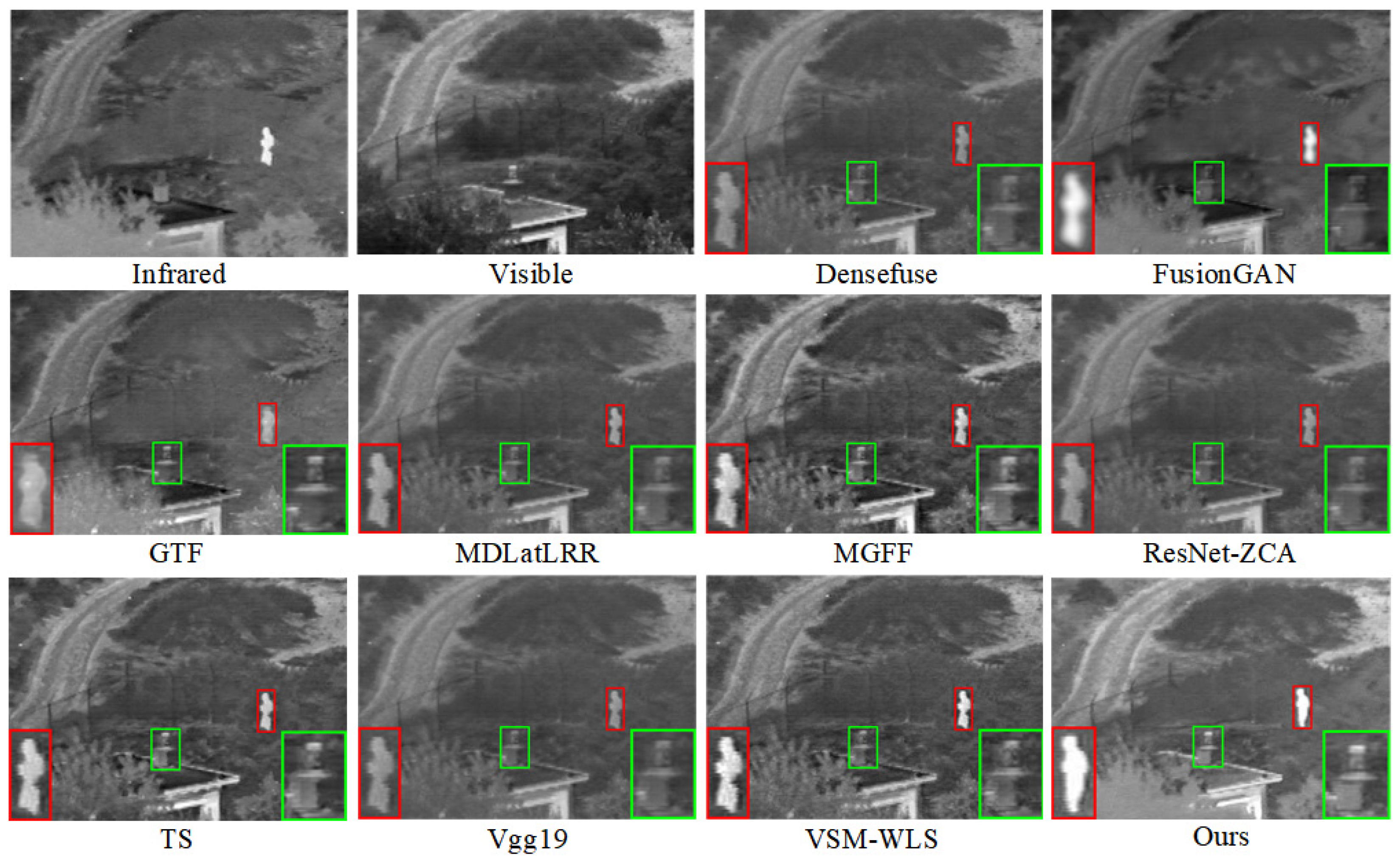
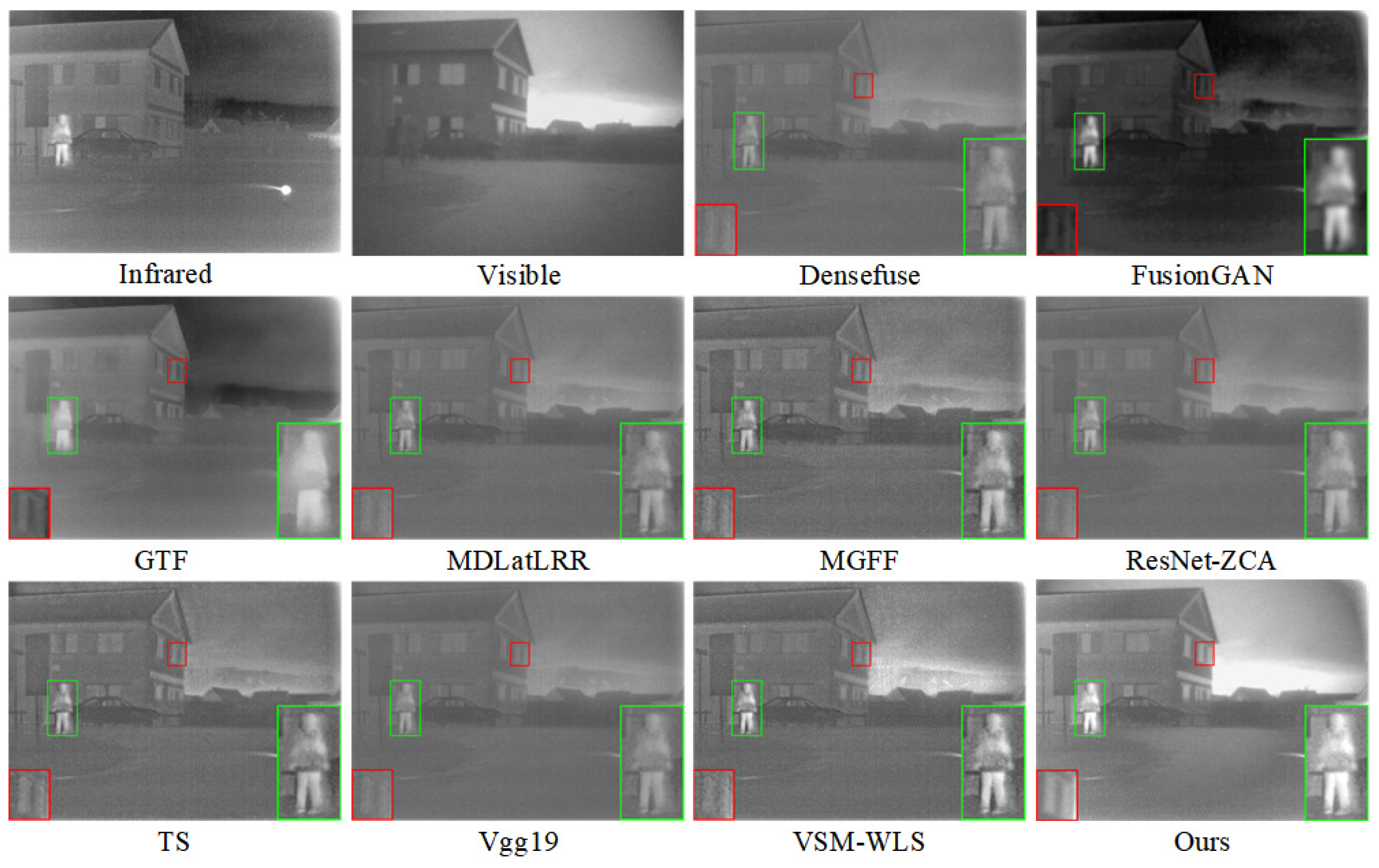
To solve these defects, we propose a novel fusion framework (MGFCTFuse). Figure 1 presents an objective comparison between different fusion algorithms and MGFCTFuse. The enlarged views within the red and green rectangles indicate that the proposed algorithm has more prominent infrared targets and clearer background details.
The main innovations and contributions of this paper are as follows:
  • We propose an image decomposition based on mutual guided image filtering, one which can obtain the base layer and the detail layer. On this basis, the base layer and the corresponding original image are concatenated to form the base image, and the infrared and visible detail layers are concatenated to form the detail image, where they are used as input for subsequent feature extraction.
  • We design an SE-based DenseNet module to extract the base image features, one which can refine the features along the channel dimension and enhance feature delivery. Meanwhile, a detail enhancement module is designed to enhance the contrast and texture details.
  • We propose a dual-branch feature reconstruction network based on cross-transmission, one which enhances the information exchange and integration at different levels, thus improving the quality of image fusion.
The rest of this article is organized as follows: In Section 2, a brief review is given of the theory of mutually guided image filtering. In Section 3, the MGFCTFuse algorithm is described. In Section 4, experimental analysis is carried out, with subjective evaluation, objective indicators and an evaluation of running efficiency. The full work of this article is summarized in Section 5.

2. Mutually Guided Image Filtering

Mutually Guided Image Filtering (MuGIF) [30] fully considers identical and different information of different modes within an image in the same scene. It not only effectively preserves the edges of the input image, improving edge blur issues, but also maintains the mutual structure of the two images, avoiding misleading structural inconsistencies. Therefore, in this article, MuGIF is used to decompose the original images. The principle of MuGIF will be introduced below.
MuGIF is achieved by designing related structures. First, three structures are defined, namely, mutual, inconsistent, and flat, with the premise that the two images are in the same coordinate position. The mutual structure indicates that the pixel gradients of both images are large enough. The inconsistent structure indicates that there is a difference in pixel gradients between the two images, with one being large and the other being small. The flat structure indicates that both images have small pixel gradients. The purpose of MuGIF is to maintain the mutual structure of the images and smooth out the inconsistent and flat structures. Therefore, the concept of related structure is proposed in order to formulate filtering rules. The definition of a related structure is as follows:
R ( T , I ) = ( x , y ) d { h , v } | d T ( x , y ) | | d I ( x , y ) |
where T(x, y) is the target image, I(x, y) is the guide image, h denotes the row, v denotes the column, and d denotes the first-order row gradient or column gradient.
The related structure expression measures the inconsistency of the target image relative to the reference image from a gradient perspective. If the target image belongs to an inconsistent structure at (x, y) relative to the guide image, then calculations of the local pixels average for the related structure R(T, I) will vary significantly from 1. Conversely, if the guide image belongs to a consistent structure at (x, y), then calculating the local pixels average for the related structure R(T, I) will approach 1. Based on the definition of related structure, the rules for establishing a mutual conduction filter are as follows:
arg   min T , I   α o R ( T , I ) + β o T T 0 2 2 + α r R ( I , T ) + β r I I 0 2 2
where R(T, I) and R(I, T), as smoothing terms, are the key to preserving the consistent structure while removing the inconsistent structure. T T 0 2 2 and I I 0 2 2 , as data fidelity terms, constrain T and I to avoid significant deviations from the input, thus avoiding trivial solutions. Values α o , α r , β o , β r are non-negative constants and can be adjusted for data fidelity and smoothing terms. The expression 2 represents the L2 norm.
The filtered image can be obtained by the global optimization of Equation (2). For ease of description, the algorithm of mutually guided image filtering is represented in this study as M u G I F ( T , I , α , β ) .

3. Proposed MGFCTFuse

In Section 3, we provide the details of MGFCTFuse. First, the network architecture of fusion framework is described. Second, the detailed design of network structure is explained. Finally, the loss function is introduced.

3.1. Network Structure

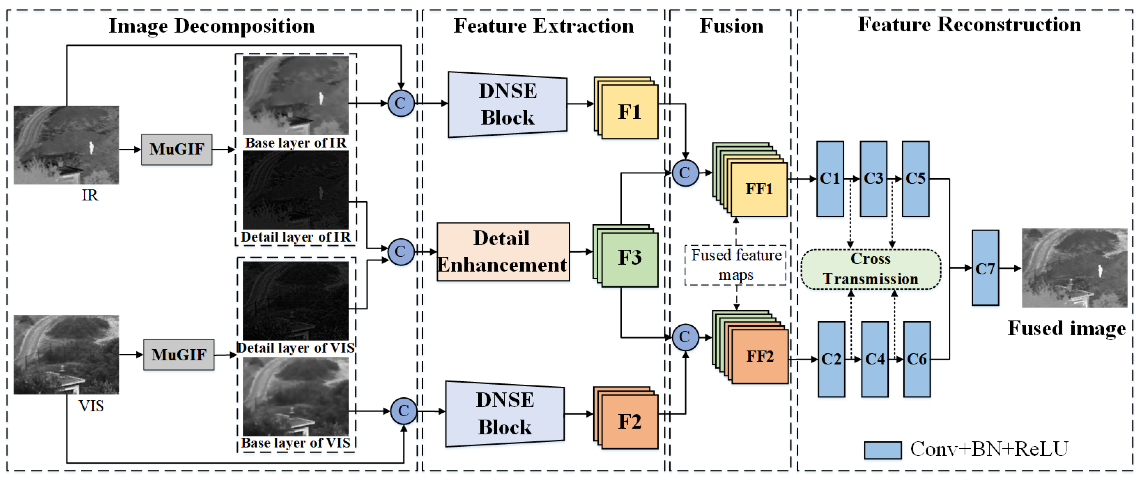
The fusion framework of the MGFCTFuse is shown in Figure 2. There are four parts of the framework: image decomposition, feature extraction, fusion, and feature reconstruction. Initially, MuGIF is used to decompose the original images into base and detail layers. Subsequently, the base layer is concatenated with the original image, serving as the input of DNSE Block. At the same time, the infrared and visible detail layers are concatenated, and the concatenation is put into the detail enhancement module. Then, the detail layer’s fusion features (F3) are fused with infrared (F1) and visible (F2) image features, resulting in fusion features FF1 and FF2. Finally, the fusion features are put into the feature reconstruction network to generate the fused image.

3.2. Details of the Network Architecture

3.2.1. Image Decomposition

MuGIF has strong structure transfer characteristics, and this can effectively smooth out inconsistencies between two original images. Therefore, an image decomposition method based on MuGIF has been designed. First, the base layers of infrared and visible images are obtained by Equation (3):
{ B 1 = M u G I F ( I R , V I S , α , β ) B 2 = M u G I F ( V I S , I R , α , β )
where α and β represent balance parameters, with α = 0.01, and β = 1. B1 and B2 represent the filtering results.
Then, the detail layers D1 and D2 are obtained by Equation (4).
{ D 1 = I R B 1 D 2 = V I S B 2
As shown in Figure 3, the base layer primarily contains the structure information of the target, and the detail layer mainly reflects texture details and edge information.

3.2.2. Feature Extraction

Given the distinct modalities and information contents of the visible and infrared images, their features are extracted via separate branches. After image decomposition, the base layers (B1, B2) and detail layers (D1, D2) can be obtained. The base layer indicates large-scale changes, and the detail layer captures small-scale changes and texture details. Then, the base layer is concatenated with the source image to form the base image, as demonstrated in Equations (5) and (6).
I v i s b a s e = c o n c a t ( B 1 , I v i s )
I i r b a s e = c o n c a t ( B 2 , I i r )
where c o n c a t   ( ) represents concatenation along channel dimensions.
(1)
DNSE Block
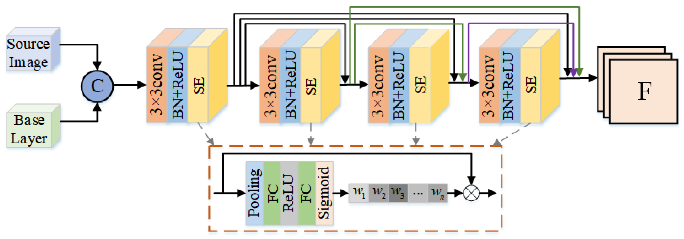
As shown in Figure 4, the base image is put into the convolution layers to extract the deeper features. During this process, a four-layer convolutional neural network is employed, with each layer utilizing 3 × 3 convolution kernels, Batch Normalization (BN), and ReLU Activation. Moreover, an SE module [31] is added after each convolutional layer, one which can help learn correlations between channels so that the extracted features are refined and enhanced. On this basis, DenseNet is also added into the feature extraction module; it can reduce the disappearance of network gradients and enhance feature delivery and reuse. For the convenience of description, this feature extraction module is briefly written as ‘DNSE Block’.
(2)
Detail Enhancement
To ensure that fusion image possess more texture detail, detail layers are also involved in the fusion process. The detail layers D1 and D2 are concatenated, and the concatenation is termed a detail image, as shown in Equation (7).
I det a i l = c o n c a t   ( D 1 , D 2 )
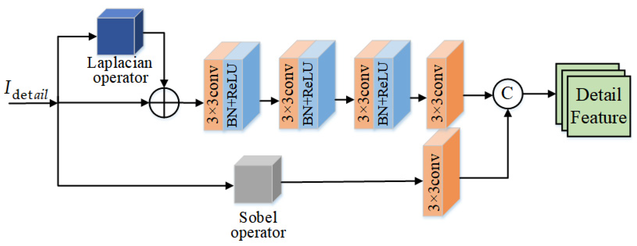
The detail enhancement module has three streams, specifically, a main stream and two residual streams, as shown in Figure 5. The main stream incorporates downsampling, which deploys four 3 × 3 convolutional layers. Downsampling expands the receptive field, providing more detailed information. The first residual stream combines the Sobel operator, to preserve texture features, with a 3 × 3 convolutional layer to eliminate differences in channel dimensions. The second residual stream utilizes the Laplacian operator to extract weak texture features. Then, the outputs of the second residual stream are added to the detail images, and these are used as the input for downsampling. The input first passes through one convolution to obtain the characteristics of 16 channels, and then undergoes multiple convolutions, expanding the number of channels to 32 and 64, in turn. Furthermore, outputs from the downsampling and first residual stream are concatenated along the channel dimension.

3.2.3. Feature Fusion

In the feature fusion network, visible features (F1) are concatenated with detail features (F3) to generate fusion feature FF1. Infrared features (F2) are concatenated with detail features (F3) to produce fusion feature FF2, as depicted in Equations (8) and (9). This approach takes into account the redundancy and complementarity between the structures of the two heterologous images, allowing the fusion image to better express complementary details during feature reconstruction.
F F 1 = c o n c a t ( F 1 , F 3 )
F F 2 = c o n c a t ( F 2 , F 3 )

3.2.4. Feature Reconstruction

In order to enhance the communication between different features, a decoding network based on cross-transmission has been designed, as shown in Figure 6. First, different fusion features from the fusion network, FF1 and FF2, are put into two independent decoding branches. Then, during the decoding process, different features can fully be exchanged, facilitating information complementarity among distinct features. Finally, the feature obtained from two branches are added together, and a convolution layer is used to generate the fused image.
The details of each convolutional layer in feature extraction and feature reconstruction are shown in Table 1.

3.3. Loss Function

The loss function consists of two parts: SSIM and gradient loss. SSIM loss primarily focuses on structural features. Gradient loss restricts the image to preserve more gradient information.
SSIM combines the structure, brightness, and contrast of the image to comprehensively measure image quality. For any two images A and B, it can be expressed by Equation (10):
S S I M ( A , B ) = ( 2 μ A μ B + C 1 ) ( 2 σ A B + C 2 ) ( μ A 2 + μ B 2 + C 1 ) ( σ A 2 + σ B 2 + C 2 )
where μ and σ represent the standard and mean deviation, and σ A B is the factor that correlates between A and B. C1 and C2 are stability coefficients, which are both small constants when the variance and mean are close to zero. In calculation, the standard deviation is set to 1.5. As suggested in [32], setting C 1 = 1 × 10 4 , and C 2 = 9 × 10 4 .
The value of the SSIM is measured by calculating the average intensity of local window pixels [33]. When E ( I i r | W ) is greater than E ( I v i | W ) , it indicates that the local window of the Iir contains more information about thermal radiation. Then, the SSIM guides the network to retain infrared image features, making the local area of the If similar to Iir, and vice versa. The expressions are shown in Equations (11) and (12):
E ( I | W ) = 1 m × n i = 1 m × n P i
S c o r e ( I f , I i r , I v i | W ) = { S S I M ( I f , I i r | W ) if   E ( I i r | W ) > E ( I v i | W ) S S I M ( I f , I v i | W ) if   E ( I i r | W ) E ( I v i | W )
L S S I M = 1 1 N W = 1 N S c o r e ( I f , I i r , I v i | W )
where W denotes the sliding window, the step size is set to 1, Pi denotes the value of pixel i, m and n are the dimensions, and N is the total number of sliding windows in a single image. In this paper, as suggested in [32], the size of a sliding window is set to 11 × 11.
To ensure the fused image retains more gradient information, a gradient loss function is introduced, as shown in Equation (14):
L g r a d = I f I v i s F 2 + I f I i r F 2
where F denotes the Frobenius norm and represents the gradient calculation.
The total loss function is the sum of SSIM loss and gradient loss, as shown in Equation (15):
L l o s s = L S S I M + L g r a d
For ease of understanding, Algorithm 1 gives the pseudo-code of the proposed MGFCTFuse.
Algorithm 1: MGFCTFuse
    Input: Infrared image(IR), visible image(VIS)
     Step1: Image decomposition
      do: Apply MuGIF on source images to obtain the base layers B1 and B2, respectively.
       { B 1 = M u G I F ( I R , V I S , α , β ) B 2 = M u G I F ( V I S , I R , α , β )
      then: Obtain the detail layers D1 and D2, respectively.
       { D 1 = I R B 1 D 2 = V I S B 2
     Step2: Image concatenation
      The detail layers, base layers, and source image are concatenated according to the rules as the input to the feature extraction network.
       I v i s b a s e = c o n c a t ( B 1 , I v i s )
       I i r b a s e = c o n c a t ( B 2 , I i r )
       I det a i l = c o n c a t ( D 1 , D 2 )
     Step3: Feature extraction
       The designed DNSE Block and detail enhancement module are used to extract image features of the concatenation to obtain the features F1, F2, and F3, respectively.
     
(1)
  Apply   DNSE   Block   on   I v i s b a s e to obtain visible feature maps F1
(2)
  Apply   DNSE   Block   on   I i r b a s e to obtain infrared feature maps F3
     
(3)
  Apply   Detail   enhancement   module   on   I det a i l to obtain detail feature maps F2
     Step4: Feature fusion
       The extracted features are fused to obtain fusion feature maps FF1 and FF2.
       F F 1 = c o n c a t ( F 1 , F 3 )
       F F 2 = c o n c a t ( F 2 , F 3 )
     Step5: Feature reconstruction
       A dual-branch feature reconstruction network based on cross-transmission in FF1 and FF2 is applied to obtain the fused image.
Output: Fused image

4. Experiments and Analysis

First, the dataset and related parameter settings required for the experiment are introduced. Then, the MGFCTFuse is compared with nine comparative algorithms according to subjective evaluation, objective indicators, and running efficiency. Finally, an ablation experimental analysis is performed.

4.1. Dataset and Parameter Settings

In this paper, the TNO [34], MSRS [35], and RoadScene [36] datasets were used for experiments. The TNO Dataset contains non-spectral night images of different military-related scenes. The MSRS dataset mainly consists of aligned visible and infrared images of multi-spectral road scenes, and the spatial resolution is 640 × 480. The images in RoadScene are derived from the FILR road scene dataset, with a spatial resolution of 500 × 329. In the experiment, we selected 32 sets of infrared and visible images in different scenarios from these datasets, all of which were grayscale versions with a bit depth of 8 bits.
In order to train a good model and enhance robustness, the dataset needs to be augmented. In this paper, 32 sets of visible and infrared images are cropped by sliding window. The cropping step was set to 12, and the cropped image block size was 120 × 120; 24,200 infrared and visible image pairs were obtained. The Adam optimizer was used to minimize the loss. The epoch and learning rate were initialized at 100 and 1 × 10⁻⁴, respectively. Moreover, the network was implemented on the Pytorch platform. The hardware platform configuration used in the all experiments: AMD Ryzen 5 5600X 6-Core Processor CPU, clocked at 3.70 GHz; and the GPU was an NVIDIA GeForce RTX 3070 8GB.

4.2. Experimental Analysis

To validate the advantages of the MGFCTFuse, 21 source images were randomly selected from three datasets for subjective and objective analysis. In addition, the MGFCTFuse was compared with Densefuse [23], FusionGAN [28], GTF [37], MDLatLRR [38], MGFF [39], ResNet-ZCA [40], TS [16], Vgg19 [41] and VSM-WLS [18], nine classical fusion algorithms.

4.2.1. Subjective Evaluation

The MGFCTFuse was subjectively compared with nine classical fusion algorithms. Some comparison results are shown in Figure 7, Figure 8, Figure 9, Figure 10, Figure 11, Figure 12 and Figure 13. For ease of observation and analysis, local details of the fusion results are boxed and enlarged.
Figure 7 displays the comparison results for ‘Kaptein_1123’, which show that the fusion images obtained by MDLatLRR, Densefuse, MGFF, TS, ResNet-ZCA and Vgg19 retain tree texture details well, but the human thermal infrared target has a certain loss. FusionGAN maintains the infrared salient target to a certain extent, but the outline of the trees and the edges of the people are blurred. GTF focuses more on extracting infrared information, which leads to the loss of tree texture detail. The VSM-WLS preserves rich infrared information, but the background of trees is not clear. The fusion result of our algorithm has richer texture detail, more prominent infrared targets, and a clearer background and outline.
The comparison results for ‘Camp’ are shown in Figure 8. Densefuse, GTF, MDLatLRR, ResNet-ZCA, and Vgg19 suffer from severe thermal infrared target information loss, such as the character information marked in the red box. FusionGAN does not fully extract visible image information, leading to a blurred and unclear target edge contour in the fused image. MGFF, TS, and VSM-WLS have noise interference, resulting in poor clarity. The fused image produced by our algorithm has more significant target contrast and background texture detail.
Figure 9 displays the comparison example for the ‘Movie_18’ image set. MGFF, TS, and VSM-WLS have better subjective effect than the other six comparison algorithms, and the character target is clearer. However, they could not preserve improved background area texture details as well, as seen, for example, in the loss of window details in the red frame callout. In contrast, our algorithm can better highlight important targets and has better visual effects.
Figure 10 displays the comparison results for ‘Sandpath’. Densefuse, MDLatLRR, ResNet-ZCA, and Vgg19 are quite similar; the fused images tend to preserve visible texture details, but typical infrared target information is still severely lost, such as the person information marked in the red box. Conversely, the result of FusionGAN tends to favor infrared information, but the edge of the target is blurred, and background texture detail is severely lost. The fusion result of GTF smooths visible details and edges without causing infrared targets to stand out, resulting in poor overall visual effects. The results of MGFF, TS and VSM-WLS are greatly improved compared with the above algorithms, but there is still local feature loss, such as the outline of the road in the green box not being clear, and the contrast is not obvious. The result of our algorithm has clearer target information and retains richer gradient information.
The comparison results for ‘FLIR_03952’ are shown in Figure 11. The results of Densefuse, FusionGAN, GTF, ResNet-ZCA, and Vgg19 show unclear thermal infrared targets, such as the character targets information marked in the green box. MDLatLRR, MGFF, TS, and VSM-WLS effectively preserve the hot target information, making the character target information clearer. However, some of the visible details and background information are lost, such as the road arrow and the background information marked in the red box. Our algorithm better preserves the target information of the characters, enriching more visible details and background information.
Figure 12 displays the comparison results for ‘00002D’. In the fusion results of Densefuse, FusionGAN, GTF, MDLatLRR, ResNet-ZCA, TS, and Vgg19, the visible targets are not clear, and the edge contours are blurred. In contrast, MGFF and VSM-WLS results show clearer car targets, but the branch texture of the tree does not retain enough information in detail, as marked in the green box. The result of our algorithm shows a clear car target and rich texture details of the tree branch.
Figure 13 displays the fusion results for ‘00839N’. The character targets of the FusionGAN and GTF are not clear, and the contours are blurred. Densufuse, MDLatLRR, ResNet-ZCA, TS, and Vgg19 retain the character target information better, but there are some details lost, such as the window detail marked in the green box not being clear. MGFF and VSM-WLS have more significant character targets, but their results are still missing some visible details; for example, the lighting part of the bicycle is not highlighted. In our result, the infrared thermal target of the character is clear and significant, and the visible detail information is rich, which has a good fusion effect.

4.2.2. Objective Analysis

Subjective evaluation has a certain degree of one-sidedness and is easily influenced by human factors. Therefore, the objective evaluation indicators, namely, entropy (EN) [42], standard deviation (SD) [43], mutual information (MI) [44], average gradient (AG) [45], and visual information fidelity (VIF) [46] are selected for analysis. The definitions of each indicator are as follows:
(1)
EN is usually used to measure the amount of information contained in the image. The larger its value, the more information the fused image contains from the source image, defined as follows:
E N = i = 0 L 1 p i log p i
p i = N ( i ) N , 0 i L 1
where L represents the pixel-level distribution of the image and p i represents the distribution of pixels with grayscale i points.
(2)
SD characterizes the degree of discretization of the information from the average value, which can reflect image distribution and contrast. The larger its value, the higher the image contrast, and the better the fusion effect of the image, defined as follows:
S D = 1 H × W i = 1 H j = 1 W ( I ( i , j ) μ ) 2
μ = 1 H × W i = 1 H j = 1 W I ( i , j )
This obtains where I(i, j) denotes the pixel gray value of image I at pixel (i, j), the image size I is H × W, and μ is the average gray value of image I.
(3)
MI is used to measure the amount of information in the fused image obtained from the source image. The larger the value, the more information is retained, and the better the quality of fusion, defined as follows:
M A , B = a , b P A , B ( a , b ) log P A , B ( a , b ) P A ( a ) P B ( b )
M I = M A , H + M B , H
where PA(a) and PB(b) represent the edge histograms of A and B, and PA, B(a,b) represents the joint histogram.
(4)
AG is used to measure the gradient information of the fused image, which can reflect the detailed texture of the image to a certain extent, defined as follows:
A G = 1 H W i = 1 H j = 1 W [ N ( i , j ) N ( i + 1 , j ) ] 2 + [ N ( i , j ) N ( i , j + 1 ) ] 2 2
where W and H denote the width and height of the fused image, respectively, and N ( i , j ) represents the pixel value at the ( i , j ) position.
(5)
VIF is usually used to evaluate the information fidelity. The larger its value, the better the subjective visual effect of the image. Its calculation is achieved through four steps, giving a simplified formula:
V I F = V I D V I N D
where VID and VIND represent the visual information of the fused image extracted from the source image.
Table 2 shows the average values of 21 sets of image evaluation indicators in three datasets; the optimal values are marked in bold.
Table 2 shows that our algorithm has the optimal values for EN, SD, MI, and VIF. The optimal EN and MI illustrate that the fused image preserves more source image information, rich texture details, and prominent targets. The optimal SD illustrates that the fusion result has better contrast information. The optimal VIF indicates that the fusion image has a high image quality and a good visual effect.

4.2.3. Running Efficiency Analysis

In addition, to further evaluate the complexity and running efficiency of our algorithm with other fusion algorithms, any five sets of images were selected for testing in three datasets, respectively. As shown in Table 3, the average running time of each algorithm was compared. The experimental results show that our algorithm has the best running efficiency on different test datasets.

4.3. Ablation Experiments

The innovation of the MGFCTFuse includes three parts: image decomposition, feature extraction, and feature decoding network based on cross-transmission. To verify each part’s superiority, ablation experiments were carried out under the following four conditions. Condition_1: The source images are directly used as input, and feature extraction and reconstruction are implemented using regular convolutions. Condition_2: On the basis of Condition_1, image decomposition is introduced, wherein the base layer is concatenated to the corresponding source image, and the two detail layers are concatenated directly. The feature extraction is performed separately; the other network structures remain unchanged. Condition_3: On the basis of Condition_2, the proposed feature extraction network is introduced, and other network structures remain unchanged. Condition_4: On the basis of Condition_3, cross-transmission is introduced in the feature reconstruction network; this condition is also known as MGFCTFuse. In the TNO, MSRS, and RoadScene datasets, the fusion results of one set of images are randomly selected for subjective comparison, and the results of 21 sets of images are selected for objective comparison.
The subjective results of the four conditions are shown in Figure 14. In Condition_1, the extracted features are not enough to retain the source image’s information, such as the aircraft fuselage target not being significant. Compared with Condition_1, Condition_2 carried out feature extraction on the basis of image decomposition, and the fused result retains more information to a certain extent, with the aircraft fuselage target being more significant. Compared with Condition_2, Condition_3 introduced a novel feature extraction network, which can enhance the contrast and texture details, and make the aircraft bottom bracket clearer. Compared with Condition_3, Condition_4 constructed a feature reconstruction network based on cross-transmission, which improved the fusion quality by strengthening information exchange between different features and levels.
As shown in Figure 15, the objective evaluation index of the ablation experiment includes EN, SD, MI and VIF. Condition_4 maintains the optimal average value among the four evaluation indicators, which verifies the advantages of our algorithm.

5. Conclusions

In the field of research of image fusion, we propose a novel fusion algorithm, MGFCTFuse. First, we designed an image decomposition method based on MuGIF. Then, the base layer was concatenated with source images to extract deeper background information, and a detail enhancement module was designed to enhance the texture details and the contrast of the detail layers. Last, in feature reconstruction, a cross-transmission network is proposed to enhance communication between different features, one which can improve the quality of the image fusion.
The results of experiment show that the MGFCTFuse not only has a better subjective effect, but that the algorithm also improves the objective evaluation indicators EN, SD, MI, and VIF by 6.82%, 37.80%, 82.84%, and 29.32%, respectively. In addition, our algorithm has good running efficiency.

Author Contributions

Conceptualization, S.H. and J.L.; methodology, S.H., J.L. and X.M.; software, J.L. and Z.T.; validation, S.H., J.L. and S.S.; formal analysis, X.M., S.S. and Z.T.; investigation, L.C.; resources, S.H. and J.L.; data curation, X.M. and L.C.; writing—original draft preparation, J.L.; writing—review and editing, S.H., J.L., X.M., S.S., Z.T. and L.C.; visualization, J.L. and S.S.; supervision, S.H.; project administration, X.M.; funding acquisition, S.H., X.M., S.S. and L.C. All authors have read and agreed to the published version of the manuscript.

Funding

This research was funded by the National Natural Science Foundation of China, grant number 51804250, the Postdoctoral Science Foundation of China, grant number 2020M683522, the Natural Science Basic Research Plan in Shaanxi Province of China, grant number 2019JQ-797, and the Basic Research Plan of Shaanxi Provincial Department of Education of China, grant number 21JK0769.

Conflicts of Interest

The authors declare no conflict of interest.

References

  1. Luo, Y.; Wang, X.; Wu, Y.; Shu, C. Infrared and Visible Image Homography Estimation Using Multiscale Generative Adversarial Network. Electronics 2023, 12, 788. [Google Scholar] [CrossRef]
  2. Ji, J.; Zhang, Y.; Lin, Z.; Li, Y.; Wang, C. Fusion of Infrared and Visible Images Based on Optimized Low-Rank Matrix Factorization with Guided Filtering. Electronics 2022, 11, 2003. [Google Scholar] [CrossRef]
  3. Li, G.; Lin, Y.; Qu, X. An infrared and visible image fusion method based on multi-scale transformation and norm optimization. Inf. Fusion 2021, 71, 109–129. [Google Scholar] [CrossRef]
  4. Tu, Z.; Li, Z.; Li, C.; Lang, Y.; Tang, J. Multi-interactive dual-decoder for RGB-thermal salient object detection. IEEE Trans. Image Process. 2021, 30, 5678–5691. [Google Scholar] [CrossRef] [PubMed]
  5. Nagarani, N.; Venkatakrishnan, P.; Balaji, N. Unmanned Aerial vehicle’s runway landing system with efficient target detection by using morphological fusion for military surveillance system. Comput. Commun. 2020, 151, 463–472. [Google Scholar] [CrossRef]
  6. Dinh, P. Combining gabor energy with equilibrium optimizer algorithm for multi-modality medical image fusion. Biomed. Signal Process. Control. 2021, 68, 102696. [Google Scholar] [CrossRef]
  7. Ma, J.; Ma, Y.; Li, C. Infrared and visible image fusion methods and applications: A survey. Inf. Fusion 2019, 45, 153–178. [Google Scholar] [CrossRef]
  8. Hao, S.; He, T.; Ma, X.; An, B.; Hu, W.; Wang, F. NOSMFuse: An infrared and visible image fusion approach based on norm optimization and slime mold architecture. Appl. Intell. 2022, 53, 5388–5401. [Google Scholar] [CrossRef]
  9. Bavirisetti, D.; Dhuli, R. Fusion of infrared and visible sensor images based on anisotropic diffusion and Karhunen-Loeve transform. IEEE Sens. J. 2015, 16, 203–209. [Google Scholar] [CrossRef]
  10. Li, S.; Yang, B.; Hu, J. Performance comparison of different multi-resolution transforms for image fusion. Inf. Fusion 2011, 12, 74–84. [Google Scholar] [CrossRef]
  11. Zhou, Z.; Dong, M.; Xie, X.; Gao, Z. Fusion of infrared and visible images for night-vision context enhancement. Appl. Opt. 2016, 55, 6480–6490. [Google Scholar] [CrossRef]
  12. Wang, J.; Peng, J.; Feng, X.; He, G.; Fan, J. Fusion method for infrared and visible images by using non-negative sparse representation. Infrared Phys. Technol. 2014, 67, 477–489. [Google Scholar] [CrossRef]
  13. Liu, Y.; Chen, X.; Ward, R.; Wang, Z. Image fusion with convolutional sparse representation. IEEE Signal Process. Lett. 2016, 23, 1882–1886. [Google Scholar] [CrossRef]
  14. Liu, Y.; Liu, S.; Wang, Z. A general framework for image fusion based on multi-scale transform and sparse representation. Inf. Fusion 2015, 24, 147–164. [Google Scholar] [CrossRef]
  15. Liu, C.; Qi, Y.; Ding, W. Infrared and visible image fusion method based on saliency detection in sparse domain. Infrared Phys. Technol. 2017, 83, 94–102. [Google Scholar] [CrossRef]
  16. Bavirisetti, D.; Dhuli, R. Two-scale image fusion of visible and infrared images using saliency detection. Infrared Phys. Technol. 2016, 76, 52–64. [Google Scholar] [CrossRef]
  17. Zhang, X.; Ma, Y.; Fan, F.; Zhang, Y.; Huang, J. Infrared and visible image fusion via saliency analysis and local edge-preserving multi-scale decomposition. J. Opt. Soc. Am. A 2017, 34, 1400–1410. [Google Scholar] [CrossRef] [PubMed]
  18. Ma, J.; Zhou, Z.; Wang, B.; Zong, H. Infrared and visible image fusion based on visual saliency map and weighted least square optimization. Infrared Phys. Technol. 2017, 82, 8–17. [Google Scholar] [CrossRef]
  19. Kong, W.; Lei, Y.; Zhao, H. Adaptive fusion method of visible light and infrared images based on non-subsampled shearlet transform and fast non-negative matrix factorization. Infrared Phys. Technol. 2014, 67, 161–172. [Google Scholar] [CrossRef]
  20. Ibrahim, R.; Alirezaie, J.; Babyn, P. Pixel level jointed sparse representation with RPCA image fusion algorithm. In Proceedings of the 2015 38th International Conference on Telecommunications and Signal Processing (TSP), Prague, Czech Republic, 9–11 July 2015; IEEE: Piscataway, NJ, USA, 2015; pp. 592–595. [Google Scholar]
  21. Li, J.; Huo, H.; Li, C.; Wang, R.; Sui, C. Multigrained attention network for infrared and visible image fusion. IEEE Trans. Instrum. Meas. 2020, 70, 5002412. [Google Scholar] [CrossRef]
  22. Yue, J.; Fang, L.; Xia, S.; Deng, Y.; Ma, J. Dif-fusion: Towards high color fidelity in infrared and visible image fusion with diffusion models. arXiv 2023, arXiv:2301.08072. [Google Scholar]
  23. Ram, P.; Sai, S.; Venkatesh, B. Deepfuse: A deep unsupervised approach for exposure fusion with extreme exposure image pairs. In Proceedings of the IEEE International Conference on Computer Vision, Venice, Italy, 22–29 October 2017; pp. 4714–4722. [Google Scholar]
  24. Li, H.; Wu, X. DenseFuse: A fusion approach to infrared and visible images. IEEE Trans. Image Process. 2018, 28, 2614–2623. [Google Scholar] [CrossRef] [Green Version]
  25. Huang, G.; Liu, Z.; van der Maaten, L.; Weinberger, K.Q. Densely connected convolutional networks. In Proceedings of the IEEE Conference on Computer Vision and Pattern Recognition, Honolulu, HI, USA, 21–26 July 2017; pp. 4700–4708. [Google Scholar]
  26. Liu, Y.; Chen, X.; Cheng, J.; Peng, H.; Wang, Z. Infrared and visible image fusion with convolutional neural networks. Int. J. Wavelets Multiresolution Inf. Process. 2018, 16, 1850018. [Google Scholar] [CrossRef]
  27. Goodfellow, I.; Pouget-Abadie, J.; Mirza, M. Generative Adversarial Networks. Adv. Neural Inf. Process. Syst. 2014, 3, 2672–2680. [Google Scholar] [CrossRef]
  28. Ma, J.; Yu, W.; Liang, P.; Li, C.; Jiang, J. FusionGAN: A generative adversarial network for infrared and visible image fusion. Inf. Fusion 2019, 48, 11–26. [Google Scholar] [CrossRef]
  29. Ma, J.; Xu, H.; Jiang, J.; Mei, X.; Zhang, X. DDcGAN: A dual-discriminator conditional generative adversarial network for multi-resolution image fusion. IEEE Trans. Image Process. 2020, 29, 4980–4995. [Google Scholar] [CrossRef]
  30. Guo, X.; Li, Y.; Ma, J. Mutually guided image filtering. In Proceedings of the 25th ACM International Conference on Multimedia, Mountain View, CA, USA, 23–27 October 2017; pp. 1283–1290. [Google Scholar]
  31. Hu, J.; Shen, L.; Aibanie, S. Squeeze-and-excitation networks. IEEE Trans. Pattern Anal. Mach. Intell. 2020, 45, 2011–2023. [Google Scholar] [CrossRef] [Green Version]
  32. Wang, Z.; Bovik, A.; Sheikh, H.; Simoncelli, E. Image quality assessment: From error visibility to structural similarity. IEEE Trans. Image Process. 2004, 13, 600–612. [Google Scholar] [CrossRef] [Green Version]
  33. Hou, R. VIF-Net: An Unsupervised Framework for Infrared and Visible Image Fusion. IEEE Trans. Comput. Imaging 2020, 6, 640–651. [Google Scholar] [CrossRef]
  34. Toet, A. The TNO multiband image data collection. Data Brief 2017, 15, 249–251. [Google Scholar] [CrossRef]
  35. Tang, L.; Yuan, J.; Zhang, H.; Jiang, X.; Ma, J. PIAFusion: A progressive infrared and visible image fusion network based on illumination aware. Inf. Fusion 2022, 83–84, 79–92. [Google Scholar] [CrossRef]
  36. Xu, H.; Ma, J.; Jiang, J.; Guo, X.; Ling, H. U2Fusion: A Unified Unsupervised Image Fusion Network. IEEE Trans. Pattern Anal. Mach. Intell. 2022, 44, 502–518. [Google Scholar] [CrossRef]
  37. Ma, J.; Chen, C.; Li, C.; Huang, J. Infrared and visible image fusion via gradient transfer and total variation minimization. Inf. Fusion 2016, 31, 100–109. [Google Scholar] [CrossRef]
  38. Li, H.; Wu, X.; Kittler, J. MDLatLRR: A novel decomposition method for infrared and visible image fusion. IEEE Trans. Image Process. 2020, 29, 4733–4746. [Google Scholar] [CrossRef] [PubMed] [Green Version]
  39. Bavirisetti, D.; Xiao, G.; Zhao, J.; Dhuli, R.; Liu, G. Multi-scale guided image and video fusion: A fast and efficient approach. Circuits Syst. Signal Process. 2019, 38, 5576–5605. [Google Scholar] [CrossRef]
  40. Li, H.; Wu, X.; Durrani, T. Infrared and visible image fusion with ResNet and zero-phase component analysis. Infrared Phys. Technol. 2019, 102, 103039. [Google Scholar] [CrossRef] [Green Version]
  41. Li, H.; Wu, X.; Kittler, J. Infrared and visible image fusion using a deep learning framework. In Proceedings of the 2018 24th international conference on pattern recognition (ICPR), Beijing, China, 20–24 August 2018; IEEE: Piscataway, NJ, USA, 2018; pp. 2705–2710. [Google Scholar]
  42. Roberts, J.; Van, J.; Ahmed, F. Assessment of image fusion procedures using entropy, image quality, and multispectral classification. J. Appl. Remote Sens. 2008, 2, 023522. [Google Scholar]
  43. Rao, Y. In-fibre Bragg grating sensors. Meas. Sci. Technol. 1997, 8, 355. [Google Scholar] [CrossRef]
  44. Qu, G.; Zhang, D.; Yan, P. Information measure for performance of image fusion. Electron. Lett. 2002, 38, 1. [Google Scholar] [CrossRef] [Green Version]
  45. Cui, G.; Feng, H.; Xu, Z.; Li, Q.; Chen, Y. Detail preserved fusion of visible and infrared images using regional saliency extraction and multi-scale image decomposition. Opt. Commun. 2015, 341, 199–209. [Google Scholar] [CrossRef]
  46. Han, Y.; Cai, Y.; Cao, Y.; Xu, X. A new image fusion performance metric based on visual information fidelity. Inf. Fusion 2013, 14, 127–135. [Google Scholar] [CrossRef]
Figure 1. Comparison diagram with different fusion algorithms.
Electronics 12 02740 g001
Figure 2. Network architecture of the fusion framework.
Electronics 12 02740 g002
Figure 3. The base layer and detail layer of the original image.
Electronics 12 02740 g003
Figure 4. DNSE Block.
Electronics 12 02740 g004
Figure 5. Detail Enhancement Module.
Electronics 12 02740 g005
Figure 6. Cross-Transmission Module.
Electronics 12 02740 g006
Figure 7. Comparison results for ‘Kaptein_1123’.
Electronics 12 02740 g007
Figure 8. Comparison results for ‘Camp’.
Electronics 12 02740 g008
Figure 9. Comparison example for ‘Movie_18’ image set.
Electronics 12 02740 g009
Figure 10. Comparison results for ‘Sandpath’.
Electronics 12 02740 g010
Figure 11. Comparison results for ‘FLIR_03952’.
Electronics 12 02740 g011
Figure 12. Comparison results for ‘00002D’ image set.
Electronics 12 02740 g012
Figure 13. Comparison results of ‘00839N’ image set.
Electronics 12 02740 g013
Figure 14. Example of subjective results of ablation experiments.
Electronics 12 02740 g014
Figure 15. Comparative results of objective indicators.
Electronics 12 02740 g015
Table 1. Details of each convolutional layer.
PartBlockLayerKernel SizeInput
Channel
Output
Channel
Activation
Feature extractionDNSE
Block
Conv1_ir/vi3 × 3216ReLU
Conv2_ir/vi3 × 31616ReLU
Conv3_ir/vi3 × 33216ReLU
Conv4_ir/vi3 × 34816ReLU
Detail
Enhancement
Conv1_L3 × 3216ReLU
Conv2_L3 × 31632ReLU
Conv3_L3 × 33264ReLU
Conv4_L3 × 36464-
Conv1_S3 × 3164-
Feature reconstructionCT
Block
Conv1_FF1/FF23 × 319264ReLU
Conv2_FF1/FF23 × 312832ReLU
Conv3_FF1/FF23 × 36432ReLU
Conv4_F3 × 3321ReLU
Table 2. Averages of 21 pairs of image evaluation indicators.
AlgorithmENSDMIAGVIF
Densefuse6.051923.62912.31422.47810.6475
FusionGAN6.316226.87132.11562.36140.5995
GTF6.711633.62172.21493.22130.6127
MDLatLRR6.294621.73862.23012.45910.6653
MGFF6.621532.45191.52194.31470.7111
ResNet-ZCA6.373625.91462.22142.66100.6984
TS6.641327.55191.55493.84970.7958
Vgg196.291023.14632.00172.54790.6664
VSM-WLS6.661936.40022.22424.76490.8126
Ours6.879638.47953.73783.38310.8922
Table 3. The average running time of each comparison fusion algorithm (units: s).
DatasetDensefuseFusionGANGTFMDLatLRRMGFF
TNO0.0911.5716.7155.3970.362
MSRS0.0851.3296.8094.9480.231
RoadScene0.0641.1126.5695.1650.134
DatasetResNet-ZCATSVgg19VSM-WLSOurs
TNO1.4810.7592.7462.0540.048
MSRS1.63280.8463.2151.5410.077
RoadScene1.3900.6693.6721.0880.058
Disclaimer/Publisher’s Note: The statements, opinions and data contained in all publications are solely those of the individual author(s) and contributor(s) and not of MDPI and/or the editor(s). MDPI and/or the editor(s) disclaim responsibility for any injury to people or property resulting from any ideas, methods, instructions or products referred to in the content.