Article

Biot–Savart-Based Design and Workbench Validation at 100 MHz of Transverse Field Surface RF Coils

by
Giulio Giovannetti
1,
Marcello Alecci
2,3,4 and
Angelo Galante
2,3,4,*
1
Institute of Clinical Physiology, National Research Council (CNR), 56124 Pisa, Italy
2
Department of Life, Health & Environmental Sciences (MESVA), University of L’Aquila, 67100 L’Aquila, Italy
3
Gran Sasso National Laboratory, Istituto Nazionale di Fisica Nucleare, 67100 L’Aquila, Italy
4
SPIN-CNR, c/o Department of Physical and Chemical Science, University of L’Aquila, 67100 L’Aquila, Italy
*
Author to whom correspondence should be addressed.
Electronics 2023, 12(12), 2578; https://doi.org/10.3390/electronics12122578
Submission received: 26 April 2023 / Revised: 22 May 2023 / Accepted: 29 May 2023 / Published: 7 June 2023
(This article belongs to the Section Bioelectronics)

Abstract

:
Radiofrequency (RF) surface coils are extensively used as receivers in magnetic resonance imaging (MRI) and magnetic resonance spectroscopy (MRS) systems thanks to their high signal-to-noise ratio (SNR). For specific magnetic resonance applications, the design of dedicated RF surface coils with a transverse (to the coil’s plane) RF magnetic field pattern can be necessary. Such transverse-field RF coils are constituted by several central linear (parallel or crossing) conductor elements connected by return current paths. Typically, the outer shape of such RF coils is circular or squared, although other geometries can be used. This paper describes the implementation and validation of a transverse-field RF surface coil simulator based on magnetostatic analysis, which permits the design and optimization of square butterfly and figure-of-eight RF coils with adjustable size and mutual distance between the central linear current elements. The simulation results, compared with the ones provided by a standard square loop RF coil, were validated with 100 MHz workbench measurements performed on three home-built prototypes. Finally, two novel quadrature RF coil structures designed by overlapping two orthogonal square butterfly and figure-of-eight RF coils were simulated and theoretically characterized. The RF coils described here should be suitable for a wide range of MRI/MRS preclinical/clinical applications, mainly at fields below 3 T.

1. Introduction

Radiofrequency (RF) coils for magnetic resonance imaging (MRI) and magnetic resonance spectroscopy (MRS) applications serve two purposes: to generate RF pulses for exciting the nuclei in the sample (transmitting coil) and to pick up the RF signals emitted by the nuclei (receiver coil). To maximize the magnetic resonance (MR) data quality, the transmitting RF coil should provide a uniform and intense RF magnetic field amplitude B1, while the receiver RF coil’s aim is a high signal-to-noise ratio (SNR). Volume RF coils are usually employed both for transmission and/or reception, while surface RF coils are mainly used as receivers due to their higher SNR, although with limited RF field spatial homogeneity [1].
The simplest surface RF coil design is a circular or square copper loop, which, in the region of interest (ROI) located around the coil’s axis, produces a B1 field perpendicular to the coil plane whose amplitude decreases along its axis. Differently shaped surface RF coils have been proposed over the years, aiming to improve performance with respect to the coil’s geometric parameters and the ROI position [2].
Several attempts have been made to exploit the B1 field parallel to the coil plane with surface coils of different designs (Table 1). Idiyatullin et al. [3] proposed dental imaging with an intraoral approach by exploiting the transverse components of the B1 field of an oriented surface RF coil with loop topology. More recently, it was reported that the RF coil axis has to be located at a certain angle relative to B0 due to different orientation of the target organ or position of the patient on the bed, as in the case of MR-PET multimodal imaging performed for prostate cancer investigations [4].
Moving on to different surface coil topologies, the so-called RF butterfly coil (BC) and figure-of-eight coil (FC) have a geometry such that the currents flowing in the two central elements produce a B1 field that, in the ROI located around the coil’s axis, has a direction orthogonal to the axis and parallel to the RF coil plane [5]. Considering the sample as a cylinder with a horizontal axis, transverse-field RF coils, instead of standard loop coils, can lie below, above, or on the sample’s side for both vertical and horizontal B0 field MR systems. In [6], the authors investigated the suitability of circular-shaped current return path FCs to solve the problem of signal loss due to the orientation of the RF coil within the scanner. In particular, the paper by Alfonsetti et al. showed that an optimal position of the circular FC with respect to B0, which preserves the signal in the central ROI near the RF coil surface, can be found for any angular phantom orientation. A 20 MHz-tuned planar FC, constituted by two counter-wound meanders and etched from a standard printed circuit board (PCB), was designed to be employed for NMR-MOUSE, an open and portable sensor able to detect NMR signals from a volume external to the one-sided magnet, permitting access to a variety of applications not compatible with closed magnet geometries [7]. A structure constituted by two FCs placed antiparallel side by side forming a BC, which provided bigger sensitive volume for thin samples, was designed for the same portable scanner [8]. Bray et al. [9] described the use of a 12.4 MHz-tuned multi-turn BC in a unilateral magnetic resonance imaging system, where both magnet and RF coil are on one side of the sample. Their approach utilized the stray field from a disk magnet and RF excitation from the BC for exciting and detecting a signal from spins located within a volume centred on a curved line through the sample. A space-limited portable magnet (0.46 T, 1.25 kg) employed a PCB-based transmitter/receiver BC for chemical/biological assay experiments. This BC was constituted by two square spiral loops connected in series with different windings (i.e., clockwise and anticlockwise) [10]. Jonczyk et al. [11] proposed a new coil constituted by a quadrupole BC for spinal injection interventions with a 1.0 T open scanner. The use of such a coil, able to provide high signal intensities, also permitted access to patients in the prone position. Recently, Puchnin et al. [12,13] proposed a two-coil transmitter/receiver setup for small animal MR imaging at 7 T constituted by a 1H rectangular BC, implemented on a PCB substrate, and a non-resonant loop antenna with a metamaterial-inspired resonator that can be tuned over a wide frequency range for 1H, 31P, 23Na, and 13C nuclei. A 15 MHz-tuned 7 cm diameter BC was used in a standalone surface MRI system for skin imaging, specifically designed for dermatologic investigation to depths of 1 cm. Phantom tomographic images were obtained by using the so-called “rastered backprojection” technique [14]. The same system was employed for MRI of materials used in organic light-emitting diodes (OLEDs) and liquid crystal displays (LCDs), in order to investigate their performance loss due to moisture egress [15].
Within parallel MRI, a phased-array sensor constituted by a couple of rectangular FC coils was designed for application in a 0.25 T vertical field MR scanner, characterized by good RF field homogeneity and low mutual inductance between the coil elements [16]. A concentric coil array design, adopting a BC configuration, was proposed for spatial encoding in parallel MRI as an alternative to conventional linear arrays, aiming for an imaging time reduction [17]. Chacon-Caldera et al. [18] proposed a novel partially orthogonal coil pair for improving parallel imaging performance with respect to a classical configuration constituted by a BC and a single loop coil, reporting a 20% SNR increase at a target depth of 10 cm.
For non-proton MRI/MRS applications, 1H MRI is necessary for localization and field shimming within the ROI, which cannot be performed with the X-nuclei due to their intrinsic lower SNR. A structure made by two intrinsically decoupled RF coplanar coils (a single-loop RF coil for 31P MRS and a BC for 1H) was proposed [19,20], with the ability to generate two B1 fields orthogonal each other, one directed along the RF coil axis and the other directed along the RF coil plane. This dual-tuned coil configuration, by presenting intrinsic geometrical isolation, is of great interest in MRS applications since it does not require additional trap circuits or active/passive decoupling circuits [31]. The utility of a dual-tuned RF coil configuration constituted by a 1H circular loop and a 31P FC coil for MRI/MRS applications at 1.5 T was also reported in [21]. This configuration was able to provide a high SNR in 1H images and 31P spectra thanks to the excellent isolation between the RF coils, guaranteed by the optimal geometric decoupling, as confirmed in very recent literature [32]. Moreover, this RF coil configuration provides overlapping sensitive volume for the two nuclei and the ability to control both frequencies independently, with the further advantage of not requiring additional lossy elements [33]. A 13C BC tuned at 150 MHz, built with 1 mm diameter copper wire, was designed for experiments with a triple-nuclear surface coil setup for 1H, 13C, and 31P for small animal metabolic imaging at 14.1 T [22]. A dual-tuned 1H/31P transmitter/receiver coil setup was designed and built for 31P MRS of a lamb’s heart with surgically created congenital heart defects. The 31P coils were constituted by a rectangular loop and a geometrically decoupled BC made by etching a copper-clad laminate containing copper foil on one side [23]. Ha et al. [24] proposed a quadrature dual-tuned 1H/23Na coil structure containing PIN-diode switches for shifting the resonance frequency between the two nuclei. This switching process permitted the use of a 1H/23Na loop coil and a 23Na BC, driving the sodium coil in quadrature and proton one in a linear manner. Cao et al. [25] developed a dual-tuned common/mode-differential-mode (CMDM) coil characterized by independent frequency tuning capability for MRS and MRI applications. This coil, based on BC design, had two modes operating with different current paths, which permitted the measurement of the dynamics of lactate, alanine, pyruvate, and bicarbonate signals in a rat head along with acquiring 1H anatomical reference images during in vivo hyperpolarized 13C MR spectroscopy experiments. Regarding proton imaging applications, a preliminary quadrature detection surface coil was proposed by Hyde et al. [26]. This structure, constituted by a planar pair and counter-rotating current (CRC) loop-gap resonators, provide an SNR gain of 2.5 and a scanning time reduction by a factor of two respective to the single coils for temporomandibular joint imaging. Doty et al. [27] theoretically described a quadrature surface coil configuration constituted by a loop and a pair of back-to-back D coils (namely BC) generating a magnetic field orthogonal to that of the loop and orthogonal to B0. A quadrature surface coil configuration, constituted by a circular loop and a BC employed as transmitter/receiver, was used for human heart imaging at 7 T, where the coil geometry was optimized for achieving coverage across the entire heart [28]. A similar loop/BC setup was compared with a two-element square phased array, demonstrating the ability of such a quadrature coil configuration to achieve better SNR in carotid artery imaging than a standard array [29]. Kumar et al. [30] investigated the power and specific absorption rate (SAR) of quadrature configurations constituted by a circular loop and an FC or BC, and proposed optimum geometry design for maximizing SNR at a defined depth in the sample when using a single FC and BC.
Despite these studies demonstrating several applications of transverse RF coils, to our knowledge a detailed comparison between BC and FC RF configurations has not been previously reported. In more detail, the RF magnetic field pattern’s dependence on the geometrical parameters of the two transverse RF coils has not been considered for the optimization of specific clinical and experimental applications. In this work, we developed a simulator based on the Biot–Savart law for RF magnetic field pattern estimation of square butterfly coils (SBCs) and square figure-of-eight coils (SFCs). We also compared such field patterns with the ones provided by a standard RF square loop coil (SLC) of equal external size, the latter being the workhorse in many clinical MRI/MRS applications. Moreover, we performed SBC and SFC simulations varying the linear central element distance to highlight its effect in the application optimization. Workbench tests performed at 100 MHz on prototypes of the three different configurations were used to validate the simulations and characterize coils’ performances. We selected this frequency to check whether the Biot–Savart approach can still be reasonably reliable even in a regime where the generally adopted condition l λ 0 / 10 ( l is the total length of the coil’s current path, λ 0 the electromagnetic wavelength in air) is not fulfilled. Finally, two novel structures constituted by two overlapped orthogonal SBCs and SFCs were also simulated, and the theoretical results presented.
The manuscript is organized as follows: after a brief description of the Biot–Savart law, simulation of isolated SLCs, SBCs, and SFCs are presented, both for fixed and variable spacing of the central current elements, then quadrature SBC and SFC are introduced and simulated. Successively, workbench tests performed on three SLC, SBC, and SFC prototypes are described. Finally, discussion and conclusions follow.

2. Materials and Methods

2.1. The Biot–Savart Law

Biot-Savart’s law, resulting from the solution of both Gauss’s and Ampere’s laws, provides an efficient formulation for calculating the static magnetic field from a steady electric current. It has great application in MRI because it permits estimation of the magnetic field pattern produced by a current flowing in a conductor, providing a fast and practical method for RF coil design.
The RF coil magnetic field simulation was performed using the magnetostatic numerical integration of the Biot–Savart law, which permits calculating the B1 field distribution in free space (unloaded coil) produced by an electric current I flowing in an arbitrary closed contour C, as in [1]:
B ( r ) = μ 0 I 4 π C d l R R 3
where μ 0 = 4 π 10 7 Henry per meter (H/m) is the free space permeability, dl is the infinitesimal vector tangential to C, and R is the distance between the observation point and the conductor path.
This equation, implemented in IDL 6.0 (Interactive Data Language, Visual Information Solutions, Boulder, CO, USA), implies the assumption of a nearly static field, a good approximation for RF coils’ dimensions much lower than the vacuum wavelength. For the determination of the B1 field profile, the conductor size can be neglected when it is much smaller than the coil’s size, and the magnetic field generated by the current elements can be evaluated considering one-dimensional current lines [34,35]. Finally, the magnetic field calculation was performed by subdividing the current lines in small segments and summing their total magnetic field contribution. A description of the code scripts and a link to download them are available in the Supplementary Materials.

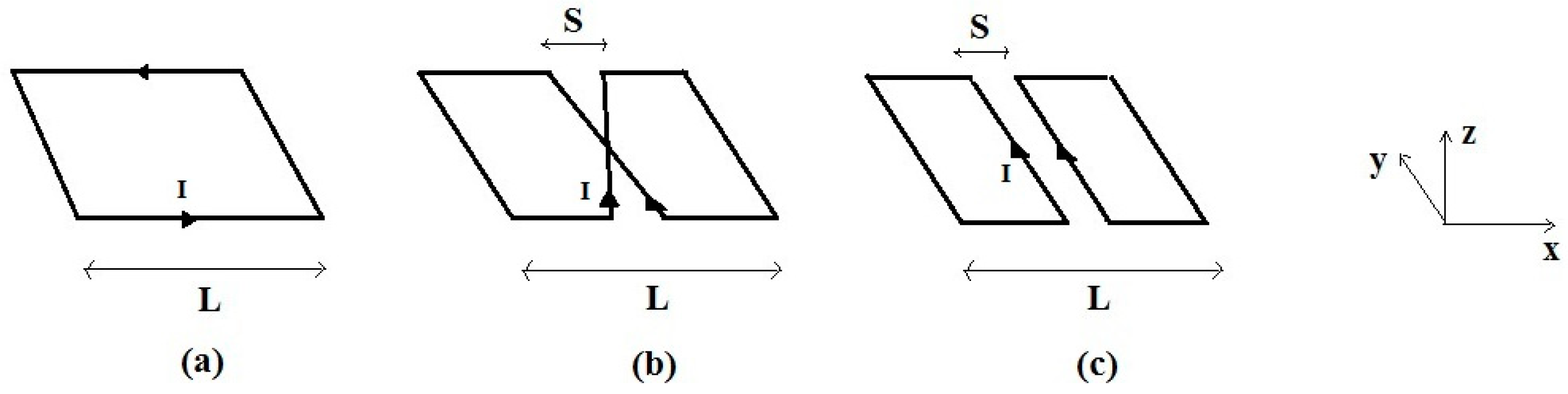
2.2. The Isolated RF Coils

Figure 1 shows the schematic models employed for simulating the magnetic field of three square RF coils: an SLC with side L; an SBC (side L, spacing S) with two linear current elements that cross at the RF coil centre, in which the current flows in the same direction; and an SFC (side L, spacing S) with two linear and parallel current elements along which the current flows in the same direction.
The SLC is an axial field surface RF coil, with B1 directed along the z-direction along the coil’s axis. The maximum RF coil sensitivity occurs close to its surface (z = 0) and decreases as the distance from the RF coil plane increases; the optimization of this configuration is rather limited, with L the only available parameter. Moreover, the maximum SNR is obtained when the coil is parallel to B0 and a reduction or even disappearance of the signal along the coil’s axis can arise when we move out from the optimal geometrical condition [6].
Conversely, the SBC and SFC are transverse-field RF coils whose B1 field, in the central area, is directed along the x-direction and the maximum SNR can be obtained for any B0 orientation within the y-z plane. For such configurations, in addition to the external size L, the separation S between the current elements provides an additional optimization parameter.

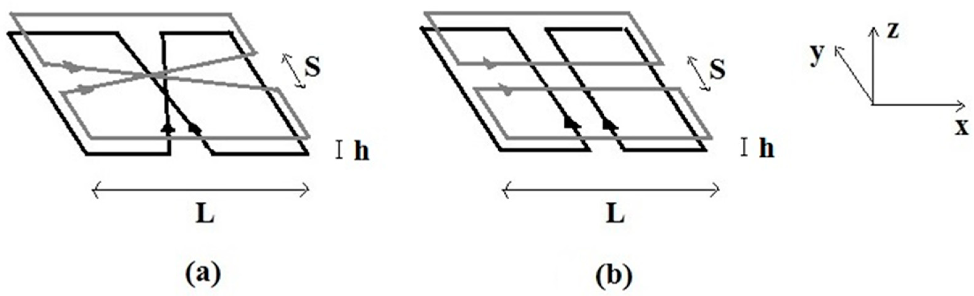
2.3. The Quadrature RF Coils

Two novel RF coil configurations, comprised either by two orthogonal SBC (Figure 2a) or SFC (Figure 2b) geometries, permit generating mutually orthogonal B1 fields in a restricted central ROI, thus allowing quadrature operation. The use of two orthogonal RF coils halves the RF drive power over the linear excitation in transmit mode and increases the SNR by a maximum factor of 2 in receiving mode [31,36]. Although we consider here quadrature configurations with transverse coils of the same external size L, we are aware that these are not optimal from the point of view of the coils’ decoupling, and better results are obtained using different L values. We are here mainly focused on the field profiles, which are roughly independent of L in the z < L region along the axis, so we preferred not to introduce extra geometrical parameters which would hinder the physical results and adopted the same L for the RF coils in the twin sets. The simulations of the RF magnetic field pattern were performed using a small distance h between the RF coil planes (Figure 2).

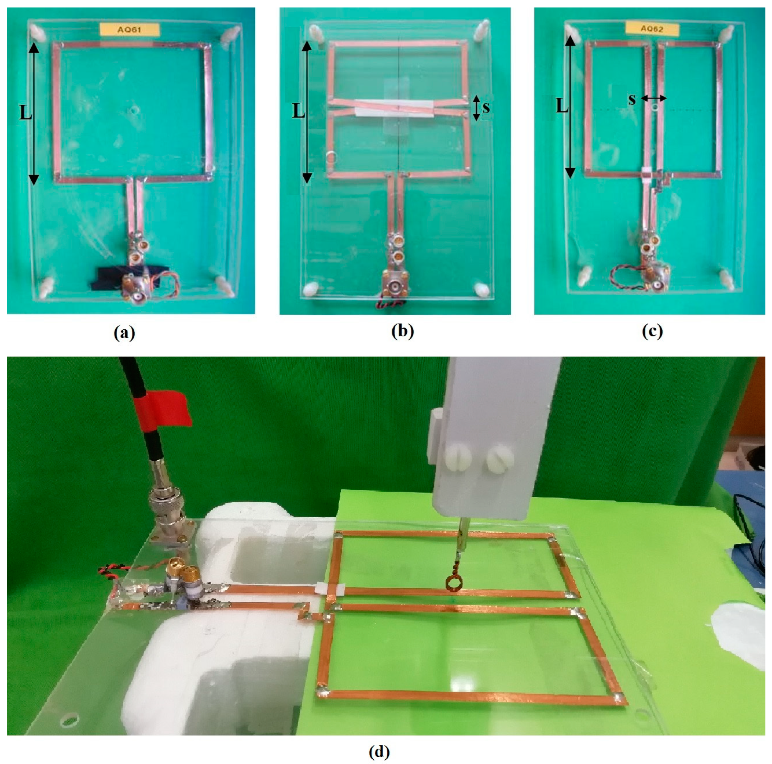
2.4. RF Coil Building and Workbench Test

Three prototypes of square RF coils matching the analytical models depicted in Figure 1 were built with L = 10 cm and S = 1 cm, shown in Figure 3. In this case the total electrical length l of the coils (considering also 10 cm for the loop input and output paths) are: l S L C = 50 cm, l S B C = l S F C = 70 cm, while λ 0 = 300 cm. Measurements were performed on the workbench by means of a Vector Network Analyser (VNA, Rhode & Swartz, Munich, Germany). The RF coils were manufactured on a Plexiglass substrate (thickness 2 mm) using adhesive copper strips (RS Components, Sesto San Giovanni, Italy) of 4 mm width and 100 μ m thickness.
The SBC and SFC were built by connecting the two sections in series, thus ensuring the equality of the currents flowing through the central linear elements. The three RF coils were tuned at 100 MHz, corresponding to the 1H frequency at 2.35 T, while a balanced capacitive matching circuit was employed for adjusting the RF coils’ impedance to 50 Ohm [31,37].
Workbench tests were performed with the VNA for reflection coefficient S11 and Q measurements, both for unloaded and loaded RF coils. The load was a 12 cm diameter cylindrical phantom filled with 2.5 L of 0.9 M saline simulating human tissues at 100 MHz and placed in proximity (6 mm) of the RF coil planes. The pickup loop method was used for mapping the RF magnetic field distribution of the three prototypes. This method measures the RF magnetic field in a given spatial position by detecting the signal induced in a small (diameter 5 mm, 2 loops) pickup coil orthogonal to the local B1 field [31,38]. To this purpose, the VNA was used to measure both the reflection (S11) and transmission (S12) coefficients between the fed RF coil and the pickup loop along the RF coil z-axis. The B1 was defined, up to a fixed unknown constant, as 10 S 12 ( z ) / 20 10 S 12 ( ) / 20 , where S 12 ( z ) is the transmitted power at depth z and S 12 ( ) is the same at very large distances from the coil and represents the signal baseline. Since S 11 was always smaller than −16 dB the correction for the reflected power is small and was discarded. Figure 3d shows the experimental setup.

3. Results

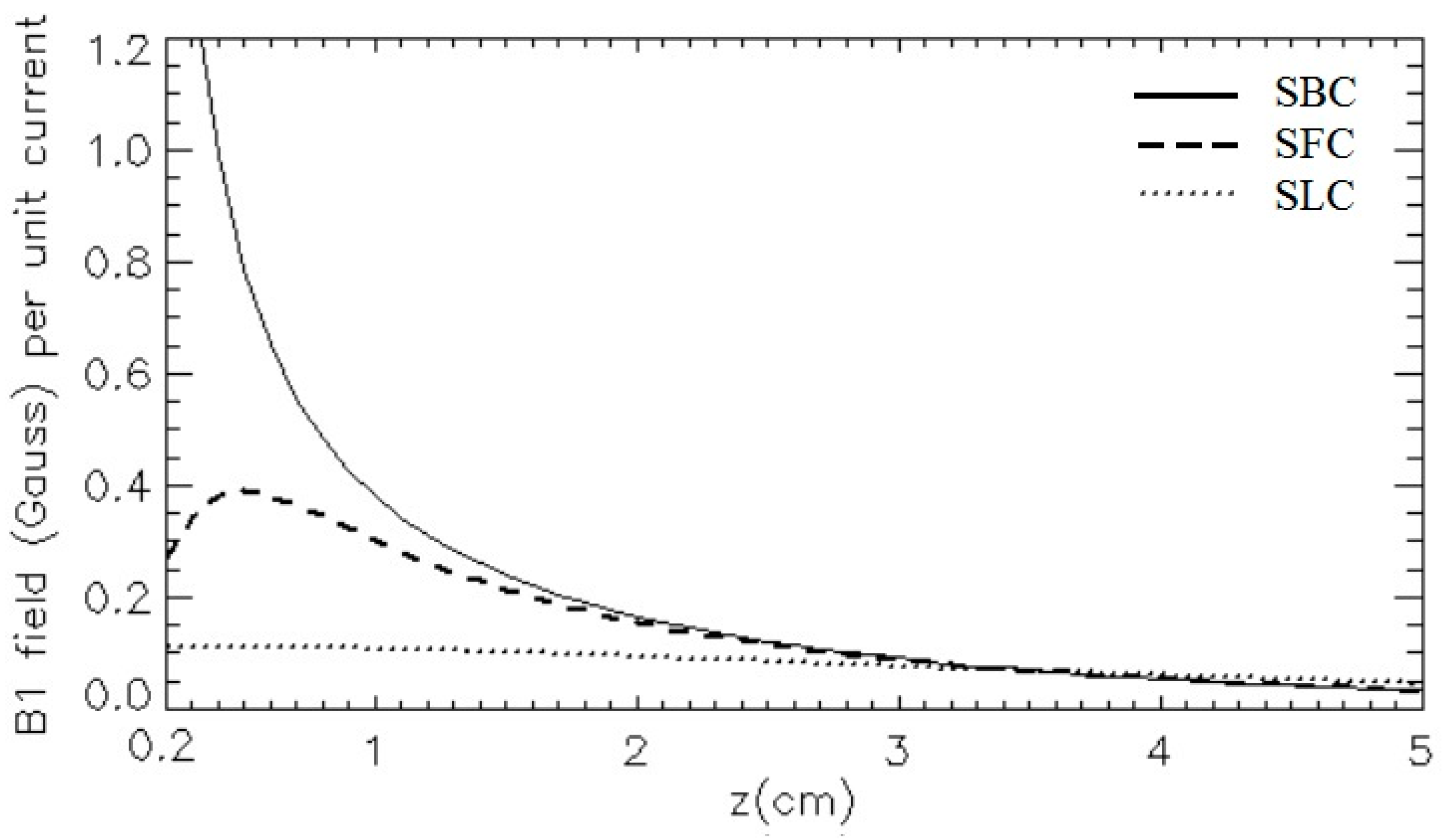
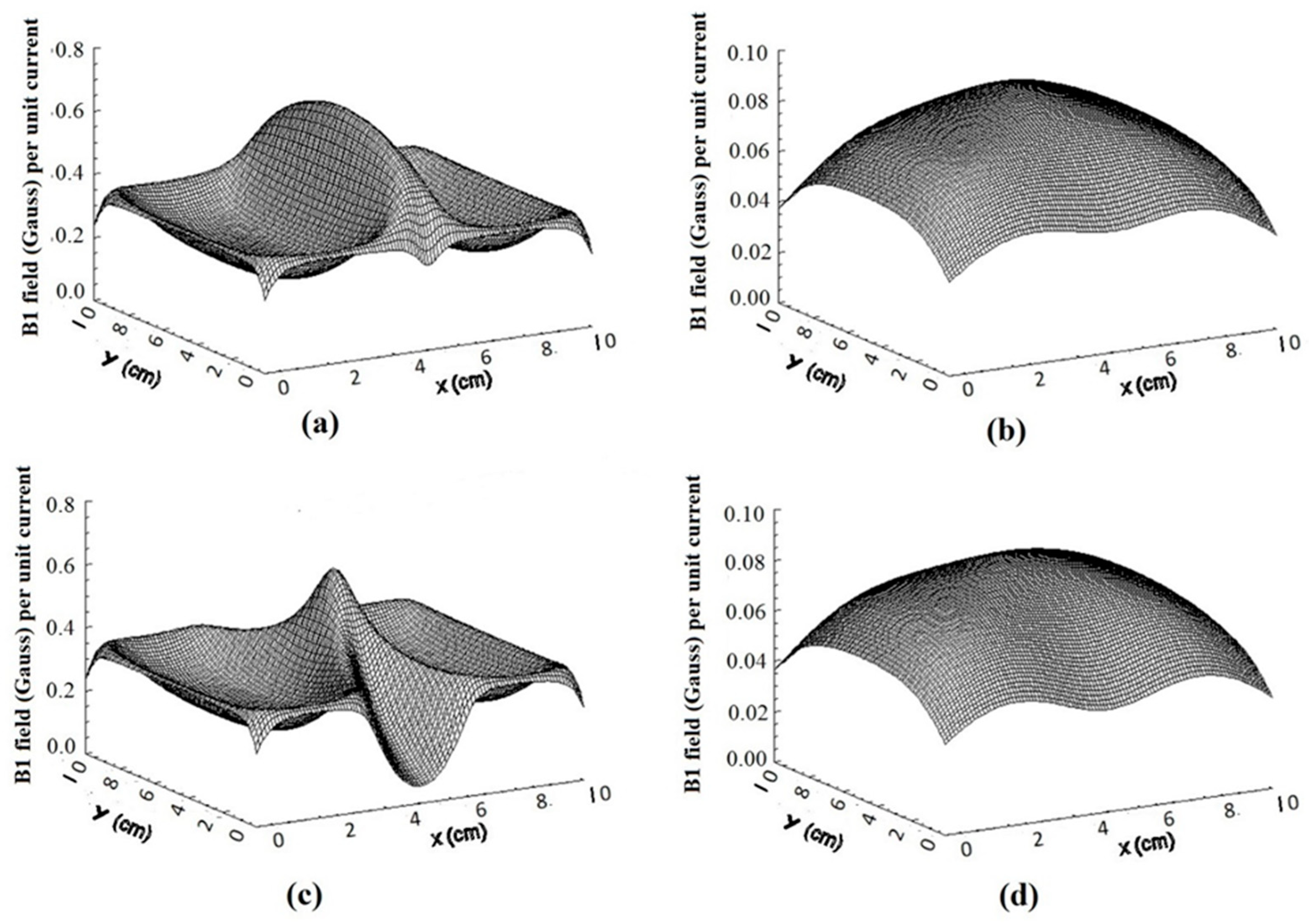
3.1. The Isolated RF Coils

A comparison between the SLC, SBC, and SFC geometries was performed. The modulus of the magnetic field pattern of the simulated RF coils, normalized to unit current and estimated in the xy planes at z = 0.6 cm and z = 3 cm, are shown in Figure 4.
From Figure 4a,c,e it can be observed that at z = 0.6 cm the B1 profiles are quite different, especially in the central area. While the SLC B1 is relatively flat in the central area and increases close to the conductors (Figure 4a), the SBC has a maximum field intensity on the RF coil axis, where the two current lines cross (Figure 4c). Finally, the SFC B1 shows two maxima along the x-axis, corresponding to the two linear current elements (Figure 4e).
Conversely, at z = 3 cm (Figure 4b,d,f) the RF field distributions become very similar, with a broad maximum on the RF coil axis. As shown in Figure 5, the SLC field pattern along the z-axis has a maximum value at z = 0 and slowly decreases moving away from the RF coil plane, reaching its half amplitude at z ≅ 4 cm. The SBC field distribution decreases rapidly with z, but at z = 1.5 cm the RF field amplitude is about three times with respect to the SLC. The SFC profile is zero at z = 0, reaches its maximum at about z = 0.5 cm, and then decreases more rapidly than the SLC. The estimated RF field amplitude of the SFC at z = 1.5 cm is about two times the one given by the SLC.

3.2. Isolated RF Coils for Variable Spacing

SBC and SFC magnetic field pattern simulations were also performed for S = 0.6 cm and S = 3 cm. As expected, the SBC simulation shows that, in proximity to the RF coil plane (z = 0.6 cm), the extent of the peak along the y-axis is broader for a small separation of the linear elements (S = 0.6 cm, Figure 6a) than for a larger one (S = 1 cm, Figure 4c; S = 3 cm, Figure 6c). For z = 3 cm we can appreciate how, when z S , the field distributions for the different spacings are similar (S = 0.6 cm, Figure 6b; S = 1 cm, Figure 4d; S = 3 cm Figure 6d). The SFC simulation shows that, in proximity to the RF coil plane (z = 0.6 cm), the two peaks along the x-axis become closer for a small separation of the linear elements (S = 0.6 cm, Figure 7a) than for a larger one (S = 1 cm, Figure 4e; S = 3 cm, Figure 7c). For z = 3 cm the minimum among the peaks is visible only for the larger separation of the linear elements (S = 3 cm, Figure 7d), not for the smaller values (S = 1 cm, Figure 4f; S = 0.6 cm, Figure 7b).
Figure 8 shows the simulated RF coil magnetic field patterns along the coils’ axis for S comprised between 0.6 and 3 cm. As expected, for the SBC coil only small variations are present (Figure 8a). For the SFC coil (Figure 8b), the position of maximum moves away from the RF coil plane (from about 0.5 cm to 1.5 cm), while the maximum RF field value diminishes considerably (by about a factor of 7).

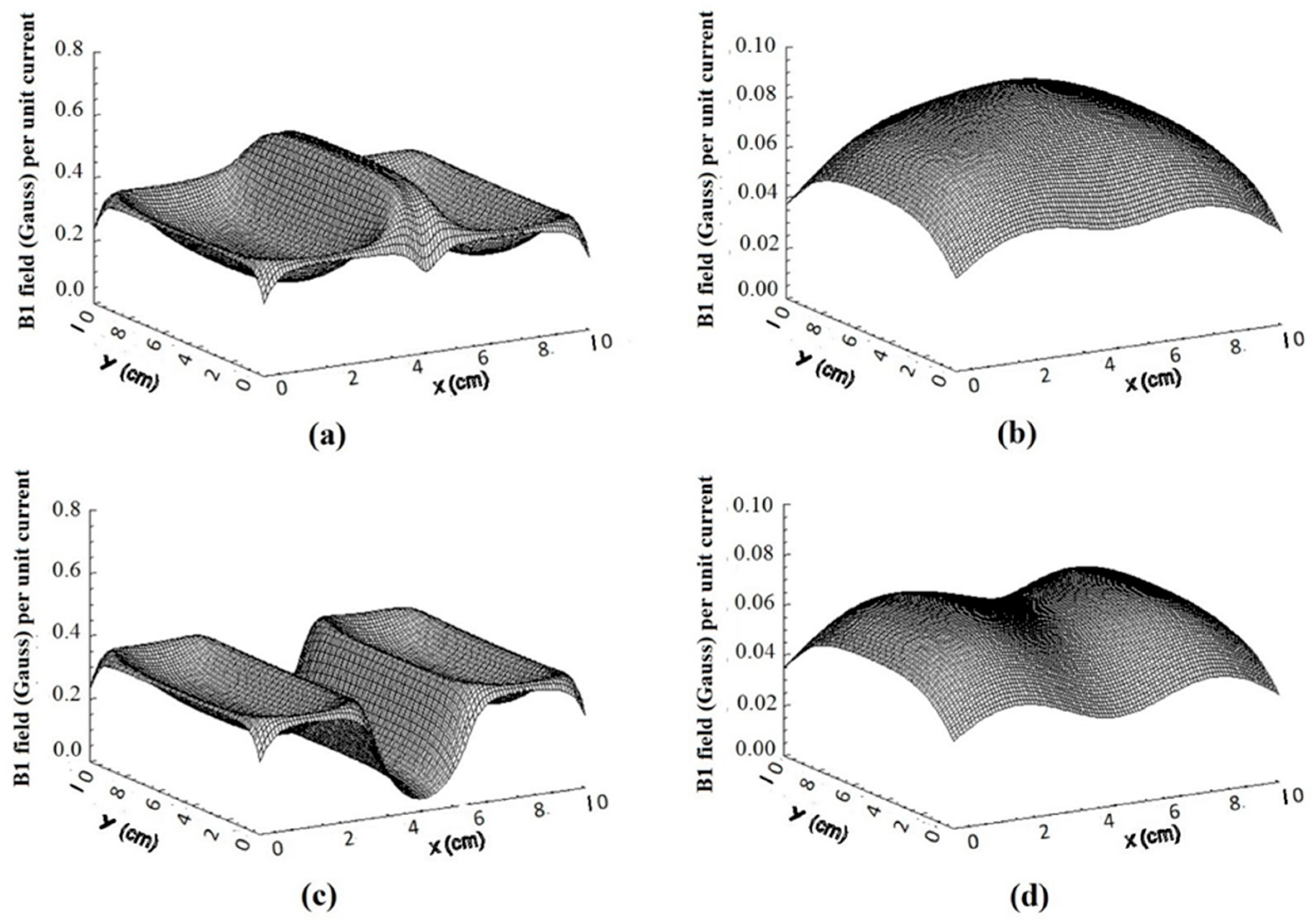
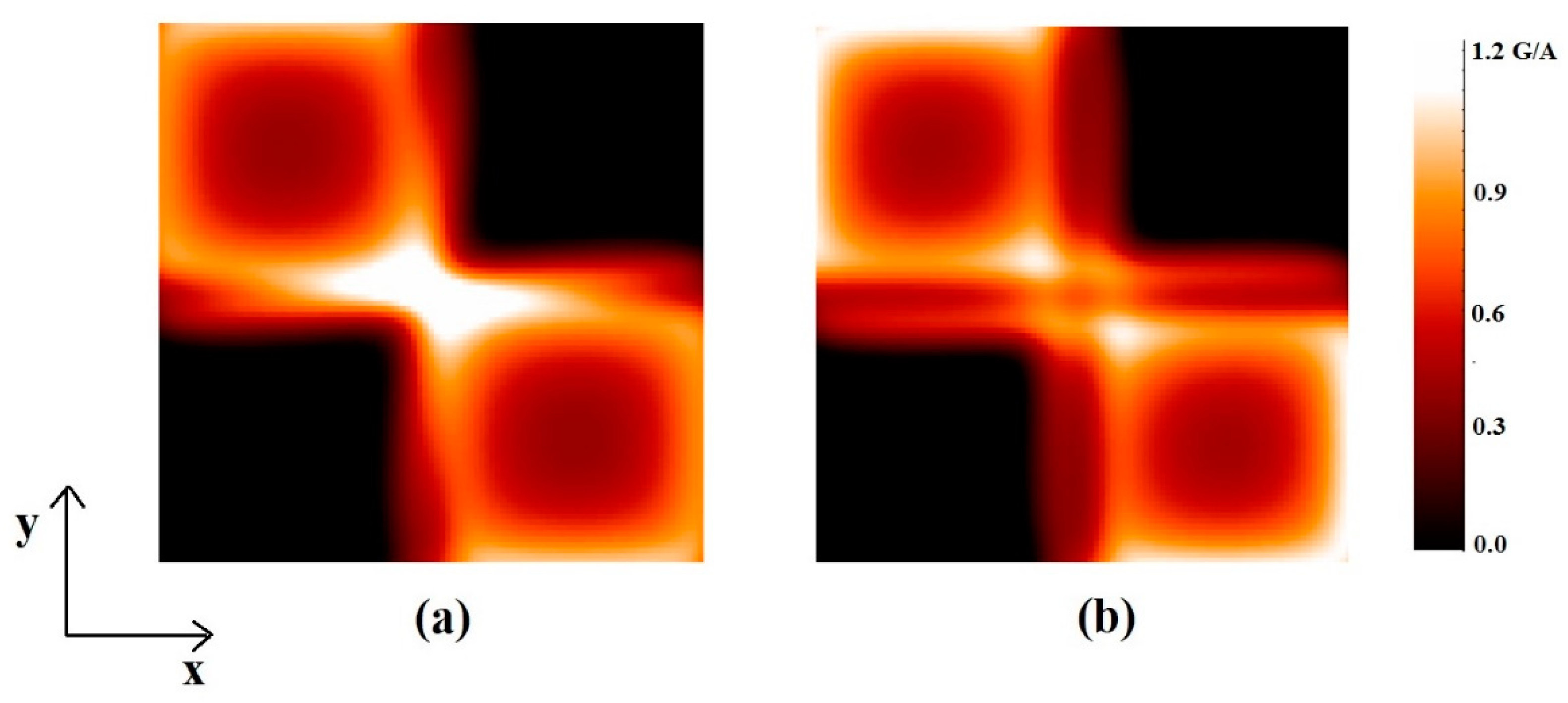
3.3. The Quadrature RF Coils

Figure 9 shows the modulus of the magnetic field patterns of the two quadrature configurations (L = 10 cm, S = 1 cm, and h = 0.8 mm), able to produce perpendicular and almost equal in modulus transverse B1 fields in a restricted region along the coils’ axis. In Figure 9 are shown the RF field calculated at z = 0.6 cm and z = 3 cm for two orthogonal SBCs (Figure 9a,b) and SFCs (Figure 9c,d).
For ease of comparison, Figure 10 depicts the RF magnetic field pattern of the quadrature SBC and SFC configurations evaluated in the xy plane at z = 0.6 cm.
Figure 11 shows the RF coil magnetic field patterns along the coils’ axis for the two quadrature configurations compared to the ones provided by the single RF coil. Both plots show the 2 RF magnetic field gain expected by the quadrature configuration.

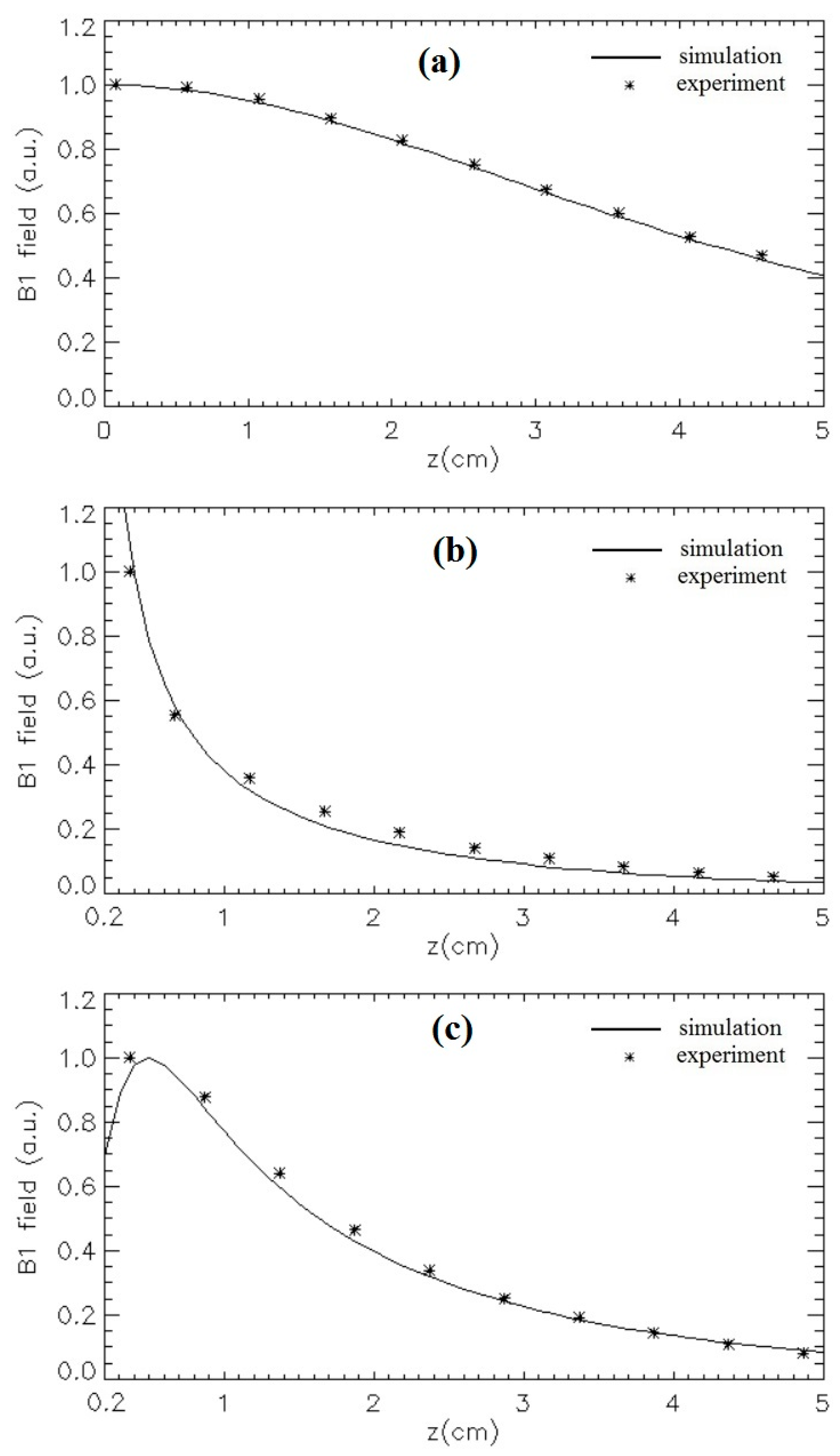
3.4. Workbench Measurements at 100 MHz

Table 2 summarizes the 100 MHz workbench measurements performed on the three isolated prototypes. We observed that for all the experimental conditions the reflection coefficient is better than —16 dB. The ratio between the unloaded to loaded Q is about 16, 11, and 5 for the SLC, SBC, and SFC, respectively.
Figure 12 shows the measured magnetic field patterns along the z-axis for the three prototypes as well as the Biot–Savart simulation. We observed an excellent agreement between simulated and experimental values, with the maximum deviation within 10%. We believe that the more pronounced discrepancy visible for the SBC geometry may be due to the sampling spatial resolution along the z-axis limited by the pick-up loop diameter, which affects the measurements with non-linear spatial gradient of the B1 field along the z-axis more.

4. Discussion

We have presented a simplified simulation approach to transverse coil design based on an unloaded configuration and Biot–Savart (i.e., magnetostatic) approach. Although a complete RF coil design should include the estimation of the loaded RF magnetic field pattern, we believe that the first design step can be performed with a priori estimation of the unloaded RF coil, useful to avoid time-consuming and expensive approaches in the RF coil design process. Moreover, as reported in the literature [39], the magnetostatic assumption is often verified at frequencies routinely used in clinical MRI applications.
The magnetostatic approach provided, in air, good results for the transverse coils even if λ 0 / l 4.3 . This can be explained with the observation that for SBC and SFC coils the main contribution to the transverse field along the coil’s axis is generated by the central current elements. Their electrical distance (related to the phase shift of the currents) is d = l / 2 and, in our case, λ 0 / d is very close to 10. In this work we demonstrated, via workbench measurements, that numerical computations based on the Biot–Savart law provide, at 100 MHz, reasonably accurate RF field values in a very short computation time (seconds) as compared to the full wave methods (hours) [40,41,42,43]. This gives confidence that this approach could be useful at lower frequencies as well or, appropriately reducing the coil size L (hence the current path l ), even at higher frequencies (3T or above).
As showed by the simulations, in planes parallel to the RF coil surface, or along the axis perpendicular to it, the RF magnetic field spatial distribution is quite different for the SBC and SFC designs. As seen in Figure 4c, close to the RF coil surface (z = 0.6 cm) we can take advantage of different geometries according to the specific application. For example, the SFC is the ideal geometry in the clinical investigation of elongated anatomical areas (RF strip), such as muscles, limbs, or spines, while the SBC is more useful when a highly sensitive central area is required (RF hot spot).
The SFC has a magnetic field pattern with a high spatial inhomogeneity and a maximum at some distance from the RF coil plane (Figure 5). This can be exploited for specific clinical applications when spatial selectivity is useful to obtain the maximum SNR at a certain depth in the sample, while attenuating the signal from both the superficial layers (skin, fat) and the deep tissues (muscle). Conversely, the SBC exhibits a higher magnetic field amplitude near the RF coil plane with respect to the SLC and SFC. This can be useful when a high MR signal is required in proximity to the sample surface, for example, in the detection of local recurrence after mastectomy in breast cancer patients [44]. Another use of the SBC design could be in high-resolution MRI to visualise the anatomy of different skin layers with the aim of providing a wide range of in vivo bio-physical clinical parameters, such as skin hydration [45] and psoriasis [46].
Furthermore, with respect to the SLC, the SBC and SFC geometries are inherently more complex, allowing for a greater versatility in the shaping of the RF field spatial distribution within the selected central VOI. Such versatile magnetic field patterns suggest the possibility of using the SBC and SFC for MRS studies, with special emphasis for highly localized tumours.
Regarding novel potential applications of SBC/SFC configurations, the literature has previously reported combined MRI and magnetic particle hyperthermia for cancerous tumour treatment. In these applications, the same MRI transverse RF coil could be used for the RF hyperthermia field source, especially when the target tissue is at a shallow depth, either by parallel connection to the hyperthermia RF coil or by a practice of timesharing [47]. If the same RF coil is used for imaging/hyperthermia, the SBC could provide a small region of strong magnetic field adjacent to the RF coil, which rapidly decreases with both distance from the coil plane and distance from the coil’s axis. This ability to concentrate the magnetic field in a “hot spot” could be employed for treating superficial tumours. Conversely, the SFC could be used for focalising the magnetic field at a certain depth in the sample tumour without damaging the healthy superficial tissues overlaying it.
Finally, our simulations show that the SNR of transverse RF coils can be improved by a factor of up to 2 by combining two SBCs or two SFCs in a quadrature configuration, which is able to produce orthogonal B1 fields in a restricted central ROI. Moreover, the use of receive-only multi-element double-tuned transverse RF coils seems feasible for improved sensitivity and spatial selectivity when coupled with transmit-only double-tuned volume birdcage RF coils [48].

5. Conclusions

This paper describes the implementation of a transverse coil simulator able to predict, in real time, the RF magnetic field pattern within the magnetostatic approximation. The simulator was validated for three widely used surface coil geometries (SLC, SBC, and SFC) home-built for this purpose, and the 100 MHz workbench test results provided an accuracy evaluation. Agreement with Biot–Savart and experimental results show how the electrical distance among the central current elements is the relevant physical parameter to be considered for assessing the validity of the magnetostatic approach, thus extending the applicability of the latter. Moreover, the simulator was employed for the design of two novel quadrature RF coil structures constituted by two overlapped orthogonal SBCs or SFCs. We believe this work contains information useful for graduate students and researchers involved in the design of MRI/MRS RF coils.

Supplementary Materials

The following supporting information can be downloaded at: https://www.mdpi.com/article/10.3390/electronics12122578/s1.

Author Contributions

Conceptualization, G.G., M.A. and A.G.; methodology, G.G., M.A. and A.G.; software, G.G.; validation, G.G., A.G. and M.A.; writing—original draft preparation, G.G., M.A. and A.G.; writing—review and editing, G.G., M.A. and A.G.; preparation and revision of the article, G.G., M.A. and A.G.; critical revision of the article, G.G., M.A. and A.G. All authors have read and agreed to the published version of the manuscript.

Funding

This research received no external funding.

Data Availability Statement

Experimental data are available in the Supplementary Materials.

Acknowledgments

We thank Maria Alfonsetti for providing a preliminary implementation of the simulation code.

Conflicts of Interest

The authors declare that they have no conflict of interest.

References

  1. Jin, J. Electromagnetic Analysis and Design in Magnetic Resonance Imaging; CRC: Boca Raton, FL, USA, 1999. [Google Scholar]
  2. Haase, A.; Odoj, F.; Von Kienlin, M.; Warnking, J.; Fidler, F.; Weisser, A.; Nittka, M.; Rommel, E.; Lanz, T.; Kalusche, B.; et al. NMR probeheads for in vivo applications. Conc. Magn. Reson. 2000, 12, 361–388. [Google Scholar] [CrossRef]
  3. Idiyatullin, D.; Corum, C.A.; Nixdorf, D.R.; Garwood, M. Intraoral Approach for Imaging Teeth Using the Transverse B1 Field Components of an Occlusally Oriented Loop Coil. Magn. Reson. Med. 2014, 72, 160–165. [Google Scholar] [CrossRef] [Green Version]
  4. Choi, C.-H.; Felder, T.; Felder, J.; Tellmann, L.; Hong, S.-M.; Wegener, H.-P.; Shah, N.J.; Ziemons, K. Design, evaluation and comparison of endorectal coils for hybrid MR-PET imaging of the prostate. Phys. Med. Biol. 2020, 65, 115005. [Google Scholar] [CrossRef] [PubMed]
  5. Alfonsetti, M.; Sotgiu, S.; Alecci, M. A Theoretical and Experimental Study on Transverse-Field Radio-Frequency Surface Coils. Measurement 2010, 43, 1503–1515. [Google Scholar] [CrossRef]
  6. Alfonsetti, M.; Clementi, V.; Iotti, S.; Placidi, G.; Lodi, R.; Barbiroli, B.; Sotgiu, A.; Alecci, M. Versatile coil design and positioning of transverse-field RF surface coils for clinical 1.5-T MRI applications. Magn. Reson. Mat. Phys. Biol. Med. 2005, 18, 69–75. [Google Scholar] [CrossRef] [PubMed]
  7. Anferova, S.; Anferov, V.; Adams, M.; Blumler, P.; Routley, N.; Hailu, K.; Kupferschlager, K.; Mallett, M.J.D.; Schroeder, G.; Sharma, S.; et al. Construction of a NMR-MOUSE with Short Dead Time. Conc. Magn. Reson. Part B Magn. Reson. Eng. 2002, 15, 15–25. [Google Scholar] [CrossRef]
  8. Blumich, B.; Anferov, V.; Anferova, S.; Klein, M.; Fechete, R.; Adams, M.; Casanova, F. Simple NMR-MOUSE with a Bar Magnet. Conc. Magn. Reson. Part B Magn. Reson. Eng. 2002, 15, 255–261. [Google Scholar] [CrossRef]
  9. Bray, C.L.; Hornak, J.P. Unilateral MRI using a rastered projection. J. Magn. Reson. 2007, 188, 151–159. [Google Scholar] [CrossRef]
  10. Lei, K.-M.; Mak, P.-I.; Law, M.-K.; Martins, R.P. A μNMR CMOS Transceiver Using a Butterfly-Coil Input for Integration with a Digital Microfluidic Device Inside a Portable Magnet. IEEE J. Solid-State Circuits 2016, 51, 2274–2286. [Google Scholar] [CrossRef]
  11. Jonczyk, M.; Hamm, B.; Heinrich, A.; Thomas, A.; Rathke, H.; Schnackenburg, B.; Güttler, F.; Teichgräber, U.K.M.; de Bucourt, M. Initial clinical experience with a quadrupole butterfly coil for spinal injection interventions in an open MRI system at 1.0 tesla. Biomed. Tech. 2014, 59, 39–45. [Google Scholar] [CrossRef]
  12. Puchnin, V.; Ivanov, V.; Gulyaev, M.; Pirogov, Y.; Zubkov, M. Imaging Capabilities of the 1H-X-Nucleus Metamaterial-Inspired Multinuclear RF-Coil. IEEE Trans. Med. Imaging 2022, 41, 1587–1595. [Google Scholar] [CrossRef]
  13. Puchnin, V.; Ivanov, V.; Gulyaev, M.; Zubkov, M. Magnetic resonance imaging with a multi-tunable metamaterial-inspired radiofrequency coil. J. Phys. Conf. Ser. 2021, 2015, 012171. [Google Scholar] [CrossRef]
  14. Hornak, J.P.; Bray, C.L.; Lucero, T.; Bright, A. Surface MRI Using a Rastered Backprojection. In Proceedings of the International Society for Magnetic Resonance in Medicine, 14th Scientific Meeting, Seattle, DC, USA, 6–12 May 2006; p. 1354. [Google Scholar]
  15. Bray, C.L.; Hornak, J.P. Design Iterations and Performance Enhancement for a Sub-Surface MRI System. In Proceedings of the 46th ENC, Providence, RI, USA, 10–15 April 2005. [Google Scholar]
  16. Giovannetti, G.; Viti, V.; Positano, V.; Santarelli, M.F.; Landini, L.; Benassi, A. Magnetostatic simulation for accurate design of low field MRI phased-array coils. Conc. Magn. Reson. Part B Magn. Reson. Eng. 2007, 31, 140–146. [Google Scholar] [CrossRef]
  17. Ohliger, M.A.; Greenman, R.; McKenzie, C.A.; Sodickson, D.K. Concentric Coil Arrays for Spatial Encoding in Parallel MRI. In Proceedings of the 9th Annual Meeting of the International Society for Magnetic Resonance in Medicine, Glasgow, Scotland, 21–27 April 2001. [Google Scholar]
  18. Chacon-Caldera, J.; Malzacher, M.; Schad, L.R. Partially orthogonal resonators for magnetic resonance imaging. Sci. Rep. 2017, 7, 42347. [Google Scholar] [CrossRef] [PubMed] [Green Version]
  19. Klomp, D.W.J.; Collins, D.J.; van der Boogert, H.I.; Schwarz, A.; Rijpkema, M.; Prock, T.; Payne, G.S.; Leach, M.O.; Heershap, A. Radio-frequency probe for 1H decoupled 31P MRS of the head and neck region. Magn. Reson. Imaging 2001, 19, 755–759. [Google Scholar] [CrossRef] [PubMed]
  20. Lei, H.; Zhu, X.-H.; Zhang, X.-L.; Ugurbil, K.; Chen, W. In vivo 31P magnetic resonance spectroscopy of human brain at 7 T: An initial experience. Magn. Reson. Med. 2003, 49, 199–205. [Google Scholar] [CrossRef]
  21. Alfonsetti, M.; Sotgiu, A.; Alecci, M. Design and testing of a 1.5 Tesla double-tuned (1H/31P) RF surface coil with intrinsic geometric isolation. Measurement 2010, 43, 1266–1276. [Google Scholar] [CrossRef]
  22. Leynes, A.P.; Chen, Y.; Sukumar, S.; Xu, D.; Zhang, X. A Compact Planar Triple-Nuclear Coil for Small Animal 1H, 13C, and 31P Metabolic MR Imaging at 14.1 T. arXiv 2021, arXiv:2109.03015. [Google Scholar]
  23. Thapa, B.; Kaggie, J.; Sapkota, N.; Frank, D.; Jeong, E.-K. Design and Development of a General-PurposeTransmit/Receive (T/R) Switch for 3T MRI, Compatible for a Linear, Quadrature and Double-Tuned RF Coil. Conc. Magn. Reson. Part B Magn. Reson. Eng. 2016, 46, 56–65. [Google Scholar] [CrossRef] [Green Version]
  24. Ha, Y.; Choi, C.-H.; Shah, N.J. Development and Implementation of a PIN-Diode Controlled, Quadrature-Enhanced, Double-Tuned RF Coil for Sodium MRI. IEEE Trans. Med. Imaging 2018, 37, 1626–1631. [Google Scholar] [CrossRef]
  25. Cao, P.; Zhang, X.; Park, I.; Najac, C.; Nelson, S.J.; Ronen, S.; Larson, P.E.Z. 1H-13C Independently Tuned Radiofrequency Surface Coil Applied for In Vivo Hyperpolarized MRI. Magn. Reson. Med. 2016, 76, 1612–1620. [Google Scholar] [CrossRef] [PubMed] [Green Version]
  26. Hyde, J.S.; Jesmanowicz, A.; Grist, T.M.; Froncisz, W.; Kneeland, J.B. Quadrature Detection Surface Coil. Magn. Reson. Med. 1987, 4, 179–184. [Google Scholar] [CrossRef] [PubMed]
  27. Doty, F.D.; Entzminger, G.; Kulkarni, J.; Pamarthy, K.; Staab, J.P. Radio frequency coil technology for small-animal MRI. NMR Biomed. 2007, 20, 304–325. [Google Scholar] [CrossRef]
  28. Versluis, M.J.; Tsekos, N.; Smith, N.B.; Webba, A.G. Simple RF design for human functional and morphological cardiac imaging at 7 tesla. J. Magn. Reson. 2009, 200, 161–166. [Google Scholar] [CrossRef]
  29. Ouhlous, M.; Moelker, A.; Flick, H.J.; Wielopolski, P.A.; de Weert, T.T.; Pattynama, P.M.T.; van der Lugt, A. Quadrature Coil Design for High-Resolution Carotid Artery Imaging Scores Better than a Dual Phased-Array Coil Design with the Same Volume Coverage. J. Magn. Reson. Imaging 2007, 25, 1079–1084. [Google Scholar] [CrossRef] [PubMed]
  30. Kumar, A.; Bottomley, P.A. Optimized quadrature surface coil designs. Magn. Reson. Mater. Phys. 2008, 21, 41–52. [Google Scholar] [CrossRef] [PubMed] [Green Version]
  31. Mispelter, J.; Lupu, M.; Briguet, A. NMR Probeheads for Biophysical and Biomedical Experiments: Theoretical Principles & Practical Guidelines, 2nd ed.; Imperial College Press: London, UK, 2015. [Google Scholar]
  32. Özen, A.C.; Spreter, F.; Schimpf, W.; Fischer, J.; Ilbey, S.; Reiss, S.; Maier, A.; von Elverfeldt, D.; Heidt, T.; von zurMühlen, C.; et al. Scalable and modular 8-channel transmit and 8-channel flexible receive coil array for 19F MRI of large animals. Magn. Reson. Med. 2023, 89, 1237–1250. [Google Scholar] [CrossRef]
  33. Choi, C.-H.; Hong, S.-M.; Felder, J.; Shah, N.J. The state-of-the-art and emerging design approaches of double-tuned RF coils for X-nuclei, brain MR imaging and spectroscopy: A review. Magn. Reson. Imaging 2020, 72, 103–116. [Google Scholar] [CrossRef]
  34. Letcher, J.H. Computer-assisted design of surface coils used in magnetic resonance imaging. I. The calculation of the magnetic field. Magn. Reson. Imaging 1989, 7, 581–583. [Google Scholar] [CrossRef]
  35. Rodriguez, A.O.; Amador, R.; Rojas, R.; Barrios, F.A. Magnetic field visualisation and inductance calculation of a simple configuration surface coil at low magnetic field. Rev. Mex. Fis. E 2006, 52, 1–12. [Google Scholar]
  36. Glover, G.H.; Hayes, C.E.; Pelc, N.J.; Edelstein, W.A.; Mueller, O.M.; Hart, H.R.; Hardy, C.J.; O’Donnell, M.; Barber, W.D. Comparison of linear and circular polarization for magnetic resonance imaging. J. Magn. Reson. 1985, 64, 255–270. [Google Scholar] [CrossRef]
  37. Chen, C.N.; Hoult, D.I. Biomedical Magnetic Resonance Technology; Adam Hilger: Bristol, UK, 1989. [Google Scholar]
  38. Hoult, D.I.; Lauterbur, P.C. The sensitivity of the zeugmatographic experiment involving human samples. J. Magn. Reson. 1979, 34, 425–433. [Google Scholar] [CrossRef]
  39. de Pellegars, P.; Pan, L.; Sidi-Boulenouar, R.; Nativel, E.; Zanca, M.; Alibert, E.; Rousset, S.; Cardoso, M.; Verdeil, J.-L.; Bertin, N.; et al. Homogenous nuclear magnetic resonance probe using the space harmonics suppression method. J. Sens. Sens. Syst. 2020, 9, 117–125. [Google Scholar] [CrossRef]
  40. Gurler, N.; Ider, Y.Z. Numerical methods and software tools for simulation, design, and resonant mode analysis of radio frequency birdcage coils used in MRI. Conc. Magn. Reson. Part B Magn. Reson. Eng. 2015, 45, 13–32. [Google Scholar] [CrossRef]
  41. Vazquez, J.F.; Rodriguez, A.O. Finite-Element Electromagnetic Simulation of a Volume Coil with Slotted End-Rings for Magnetic Resonance Imaging. AIP Conf. Proc. 2008, 1032, 172–175. [Google Scholar] [CrossRef]
  42. Shan, K.; Duan, Y. Rapid four-ring birdcage coil analysis: Design optimization for high efficiency, low interference, and improved body loading tolerance. Magn. Reson. Imaging 2020, 66, 30–35. [Google Scholar] [CrossRef]
  43. Du, F.; Liu, S.; Chen, Q.; Li, N.; Dou, Y.; Yang, X.; Wang, Z.; Zhang, X.; Shen, B.; Li, Y. Numerical Simulation and Evaluation of a Four-Channel-by-Four-Channel Double-Nuclear RF Coil for 1 H MRI and 31 P MRSI at 7 T. IEEE Trans. Magn. 2018, 54, 5101105. [Google Scholar] [CrossRef]
  44. Lee, J.; Kang, B.J.; Park, G.E.; Kim, S.H. The Usefulness of Magnetic Resonance Imaging (MRI) for the Detection of Local Recurrence after Mastectomy with Reconstructive Surgery in Breast Cancer Patients. Diagnostics 2022, 12, 2203. [Google Scholar] [CrossRef]
  45. Zegour, R.; Belaid, A.; Ognard, J.; Salem, D.B. Convolutional neural networks-based method for skin hydration measurements in high resolution MRI. Biomed. Sign. Proc. Control 2023, 81, 104491. [Google Scholar] [CrossRef]
  46. Maifeld, A.; Wild, J.; Karlsen, T.V.; Rakova, N.; Wistorf, E.; Linz, P.; Jung, R.; Birukov, A.; Gimenez-Rivera, V.-A.; Wilck, N.; et al. Skin Sodium Accumulates in Psoriasis and Reflects Disease Severity. J. Investig. Dermatol. 2021, 142, 166–178.e8. [Google Scholar] [CrossRef]
  47. Cantillon-Murphy, P.; Wald, L.L.; Zahn, M.; Adalsteinsson, E. Proposing magnetic nanoparticle hyperthermia in low-field MRI. Conc. Magn. Reson. Part A 2010, 36, 36–47. [Google Scholar] [CrossRef]
  48. Fantasia, M.; Galante, A.; Maggiorelli, F.; Retico, A.; Fontana, N.; Monorchio, A.; Alecci, M. Numerical and workbench design of 2.35 T double-tuned (1H/23Na) nested RF birdcage coils suitable for animal size MRI. IEEE Trans. Med. Imaging 2020, 39, 3175–3186. [Google Scholar] [CrossRef] [PubMed]
Figure 1. Sketch of the square surface RF coils: (a) axial field SLC; (b) transverse-field SBC; (c) transverse-field SFC. The overall size is L and the separation between elements is S.
Electronics 12 02578 g001
Figure 2. Sketch of quadrature RF coil configurations constituted by (a) two SBCs; (b) two SFCs. The overall size is L, the separation between elements is S, and the distance between the RF coil planes is h.
Electronics 12 02578 g002
Figure 3. The 100 MHz RF coil prototypes: (a) SLC; (b) SBC; (c) SFC. Panel (d) shows the B1 measurement setup with the coaxial cable on the left connected to VNA port 1 and the pickup loop on the coil’s axis connected to port 2.
Electronics 12 02578 g003
Figure 4. Simulated magnetic field modulus (Gauss/A) distributions for a unit current in the RF coils (L = 10 cm, S = 1 cm): (a) SLC at z= 0.6 cm; (b) SLC at z= 3 cm; (c) SBC at z = 0.6 cm; (d) SBC at z = 3 cm; (e) SFC at z = 0.6 cm; (f) SFC at z = 3 cm.
Electronics 12 02578 g004
Figure 5. Simulated magnetic field (Gauss/A) for unit current, along the perpendicular axis, for the three RF coils of Figure 4.
Electronics 12 02578 g005
Figure 6. Simulated SBC magnetic field modulus distributions with S = 0.6 cm and z = 0.6 cm (a) or z = 3 cm (b); S = 3 cm and z = 0.6 cm (c) or z = 3 cm (d).
Electronics 12 02578 g006
Figure 7. Simulated SFC magnetic field modulus distributions with S = 0.6 cm and z = 0.6 cm (a) or z = 3 cm (b); S = 3 cm and z = 0.6 cm (c) or z = 3 cm (d).
Electronics 12 02578 g007
Figure 8. Simulated magnetic field (Gauss/A) along the z-axis for S values ranging from 0.6 to 3 cm: (a) SBC; (b) SFC.
Electronics 12 02578 g008
Figure 9. Simulated magnetic field modulus (Gauss/A) distributions for the quadrature RF coils (L = 10 cm, S = 1 cm, and h = 0.8 mm): (a) SBC at z = 0.6 cm; (b) SBC at z = 3 cm; (c) SFC at z = 0.6 cm; (d) SFC at z = 3 cm.
Electronics 12 02578 g009
Figure 10. Simulated magnetic field (Gauss/A) distributions in the xy plane at z = 0.6 cm for the quadrature RF coils (same geometry as for Figure 9): (a) SBC; (b) SFC.
Electronics 12 02578 g010
Figure 11. Simulated magnetic field (Gauss/A) along the z-axis for the single and quadrature square coils (same geometry as for Figure 9): (a) SBC; (b) SFC.
Electronics 12 02578 g011
Figure 12. Simulated (lines) and measured (symbols) RF magnetic field amplitude along the isolated coils’ axis: (a) SLC; (b) SBC; (c) SFC. For ease of comparison, the simulated fields were normalized with respect to the following values: 0.11 G/A (SLC field at z = 0 cm), 0.99 G/A (SBC field at z = 0.4 cm), and 0.39 G/A (SFC field at z = 0.5 cm).
Electronics 12 02578 g012
Table 1. List of MRI applications with transverse surface coils with operating frequencies and imaged nuclei.
RF Coil DesignFrequency (MHz)
and Nuclei
Application/Data
Circular loop [3]170.3 (1H)Dental imaging
FC [4]123.2 (1H)Prostate imaging
BC, FC [5]25.85/63.9 (31P/1H)Phantom SNR measurement
FC [6]63.9 (1H)Phantom SNR measurement
FC meander coil [7]≈20 (1H)Historical books analysis
FC. BC [8]22 (1H)Rubber process analysis
BC [9]12.4 (1H)Phantom SNR measurement
BC [10]20 (1H)Biological/chemical assays
BC [11]42.6 (1H)Human MR-guided interventions
BC [12,13]300 (1H)Phantom SNR measurement
BC [14]15 (1H)Phantom SNR measurement
BC [15]15 (1H)Phantom SNR measurement
Array of FC [16]10.6 (1H)Magnetic field estimation
Array of BC [17]63.9 (1H)Phantom SNR measurement
BC [18]128 (1H)Human brain imaging
BC [19]63.9 (1H)Head and neck imaging and spectroscopy
BC [20]298 (1H)Human brain imaging
FC [21]25.85 (31P)Phantom SNR measurement
BC [22]150 (13C)Small animal metabolic imaging
BC [23]49.9 (31P)Phantom SNR measurement
BC [24]105.7 (23Na)Phantom SNR measurement
BC [25]74.96/298.06 (13C/1H) Rat brain imaging
CRC loop-gap resonator [26]63.9 (1H)Temporomandibular joint imaging
BC [27]--- ---
BC [28]298 (1H)Human heart imaging
BC [29]63.9 (1H)Carotid artery imaging
BC, FC [30]128 (1H)Phantom SNR measurement
Table 2. Workbench test results at 100 MHz for the three isolated RF coil prototypes.
CoilS11unloaded (dB)QunloadedS11loaded (dB)Qloaded
SLC−16176−3111
SBC−23218−2320
SFC−16177−4038
Disclaimer/Publisher’s Note: The statements, opinions and data contained in all publications are solely those of the individual author(s) and contributor(s) and not of MDPI and/or the editor(s). MDPI and/or the editor(s) disclaim responsibility for any injury to people or property resulting from any ideas, methods, instructions or products referred to in the content.

