Article

3D Placement of a New Tethered UAV to UAV Relay System for Coverage Maximization

1
Department of Electronics and Electrical Communication, Faculty of Engineering, Ain Shams University, Cairo 11566, Egypt
2
College of Engineering, October 6 University, Giza 12585, Egypt
*
Author to whom correspondence should be addressed.
Electronics 2022, 11(3), 385; https://doi.org/10.3390/electronics11030385
Submission received: 15 January 2022 / Revised: 20 January 2022 / Accepted: 21 January 2022 / Published: 27 January 2022
(This article belongs to the Topic Advanced Systems Engineering: Theory and Applications)

Abstract

:
In this paper, a new relay system that uses the UAV as a relay station between the tethered UAV and ground user (TU2U2G) is proposed. The TU2U2G system uses a TUAV as a viable alternative to replace BS and provide seamless service over a cable that simultaneously supplies stable power and a reliable wired data-link connection from a ground control station. Compared to the BS, TUAV improves system coverage due to its high altitude. Also, it overcomes the antenna down-tilting, which increases the path loss between BS and UAV in the cellular system. In addition, it overcomes the UAV drawback of the batteries’ limited capacity. Therefore, TUAV can achieve the main requirements of a reliable cellular BS in terms of endurance, backhaul link quality, and the advantage of the UAV’s high altitude. After that, the optimization problem is formulated to maximize UAV relay station coverage under the power budget and maximum UAV height constraints. For simplicity, the 3D placement of the UAV is decoupled to the vertical and horizontal placement. Then, a 3D placement algorithm for the system is proposed. The UAV placement in the TU2U2G system compared to the cellular system shows better results in terms of optimum UAV height, maximum coverage radius, and maximum relaying distance.

1. Introduction

Unmanned aerial vehicles (UAVs) have become an essential component in many wireless communication systems because of their rapid deployment, mobility, and flexibility [1]. In cellular communication networks, UAVs can act as aerial base stations by mounting mobile base stations on them [2]. However, the practical limitations of UAVs prevented them from being used as a replacement for the cellular base station. These limitations include available UAV payload, endurance, and onboard available processing energy. In order to use the UAV as an aerial base station, it is required to equip the UAV with processing units and antennas. The currently UAV-available payloads are very limited. In order to increase the payload of a UAV, a stable source of energy is required, which is not available in UAVs. UAV’s limited flying time is one of the obstacles to utilizing UAVs’ BS. The UAV needs to be grounded to recharge or change the battery, which reduces the performance of the communication network. In addition, providing the required power for processing and communication using the UAV battery is a challenge. Therefore, a permanent power source for UAV is required to achieve a reliable aerial base station that can be provided using tethered UAVs (TUAVs) [3]. A TUAV is a UAV supplied by both power and data over a cable from a ground station (GS), as shown in Figure 1. The specifications of TUAVs implemented by many companies are summarized in [4]. It shows that TUAVs can fly from 10 h to an unlimited amount of time. On the other hand, TUAV has a main drawback, the limited tether length, which restricts their mobility and placement flexibility. Comparing TUAVs with cellular BSs and UAVs, TUAVs can achieve the main requirements of a reliable cellular BS in terms of endurance, backhaul link quality, and the advantage of the UAV’s high altitude, as shown in Figure 2. Recently, AT&T deployed the first TUAV to provide cellular coverage in Puerto Rico for the affected regions after Hurricane Maria [5], which means that, TUAV can be a realistic alternative to a cellular BS. To this end, we introduce TUAV as a viable alternative to replace BS. Then, we propose a new relay system that uses a UAV as a relay station between a TUAV and a ground user (TU2U2G) TU2U2G system. Then, the 3D placement of the UAV as a relay station is presented. We formulate the optimization problem to maximize UAV relay station coverage under the power budget and maximum UAV height constraints.

1.1. Related Work

Several pieces of research were presented on the placement of UAVs. In [6,7,8,9,10], the placement of UAVs for coverage maximization was proposed. Authors in [6] proposed an algorithm that jointly optimizes the 3D UAV placement and path loss compensation factor to maximize the user coverage in the uplink transmission. An approach to minimize the total transmit power required to provide wireless coverage for indoor users was presented in [7]. A placement algorithm that maximizes the number of covered users with minimum transmission power was proposed in [8]. The UAV placement that maximizes the number of served users with different quality-of-service requirements was proposed in [9]. In Reference [10], an analytical approach was used to find the optimum altitude of a UAV for maximum coverage. In References [11,12,13,14], UAV placement for throughput maximization was proposed. A joint trajectory and resource allocation algorithm for the maximization of the system sum throughput was introduced in [11]. A joint transmit power and trajectory optimization algorithm to maximize the minimum average throughput was proposed in [12]. In Reference [13], the minimum throughput of overall ground users was maximized in the downlink communication by optimizing the scheduling of multi-user communication and association jointly with the trajectory of UAVs and power control. Trajectory and resource allocation are jointly optimized for maximizing the system energy efficiency in [14]. An algorithm to maximize the downlink sum-rate of the network was proposed in [15]. An algorithm for UAV placement based on sparse recovery was presented in [16]. However, all these works consider only the power constraints of the communication link between a UAV and the ground user mobile station (MS) and don’t consider the power constraints of the communication link between a UAV and the BS. Otherwise, researchers that consider both links were presented in [17,18,19,20,21,22,23,24,25]. References [17,18,19,20,21] were proposed for throughput maximization. The 3D placement of UAV as a relay station for maximizing the average achievable rate through the one-dimensional linear search was proposed in [17]. In Reference [18], the optimization problem was formulated to maximize the system throughput. An algorithm to find the UAV’s optimal position based on LOS information to maximize the end-to-end throughput was proposed in [19]. Reference [20] explored the relationship between system throughput and the placement of a UAV acting as a communication relay. An approach to jointly optimize throughput and the UAV’s trajectory was presented in [21]. References [22,23] were proposed for data rate maximization. In Reference [22], an algorithm to find the 3D locations of UAVs besides the user-BS associations and bandwidth allocations of the wireless backhaul to maximize the sum logarithmic rate of the users was proposed. Deployment algorithms for deploying a multi-relay network to maximize the end-to-end achievable rate were presented in [23]. An approach to find the optimum altitude of a UAV that minimizes power loss, outage probability, and BER was presented in [24], while an approach to optimize the overall network delays was proposed in [25]. All these works were proposed for UAVs to assist a cellular network. However, the antenna down-tilting and low height of the cellular base station (BS) limits the ability of the UAV relay station to reach high altitudes due to the power constraint on the path between a UAV and a BS [26]. In other words, using the UAV as a relay station in the cellular system makes the UAV lose the advantage of deployment at optimum altitude, which reflects directly on the coverage [10]. Table 1 summarized the pros and cons of related work on UAV placement.

1.2. Contributions

Compare to the existing literature on the placement optimization of UAVs, which focused on assisting cellular base stations, this paper focuses on replacing a cellular base station with a TUAV. Then, the placement of UAVs is optimized to assist a TUAV for coverage maximization. Thus, the contribution of this paper resides in several aspects:
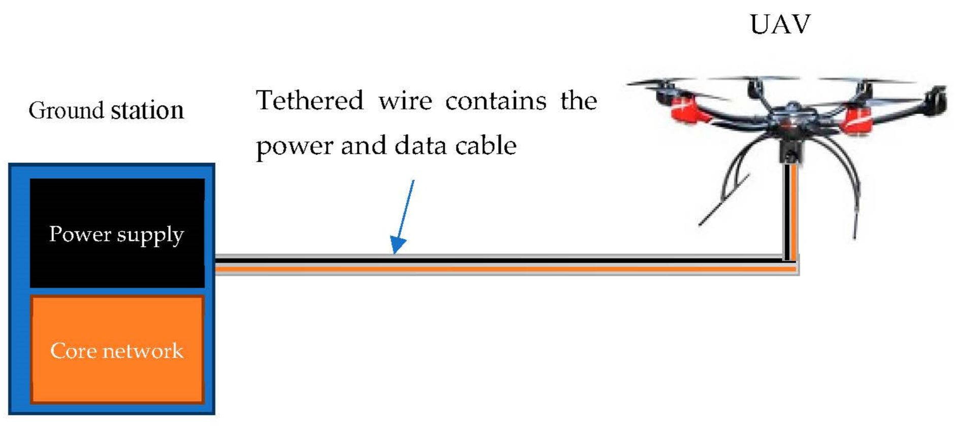
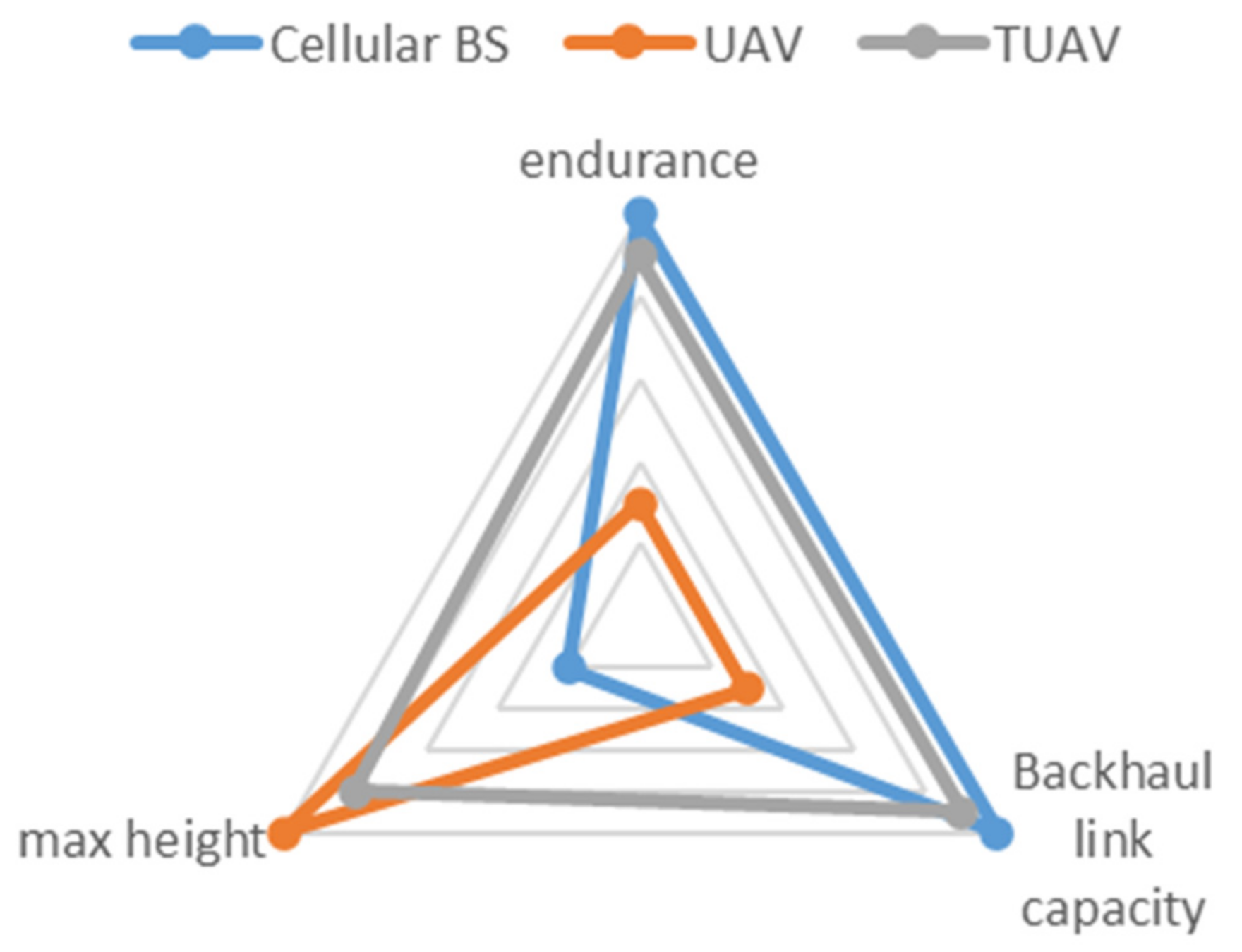
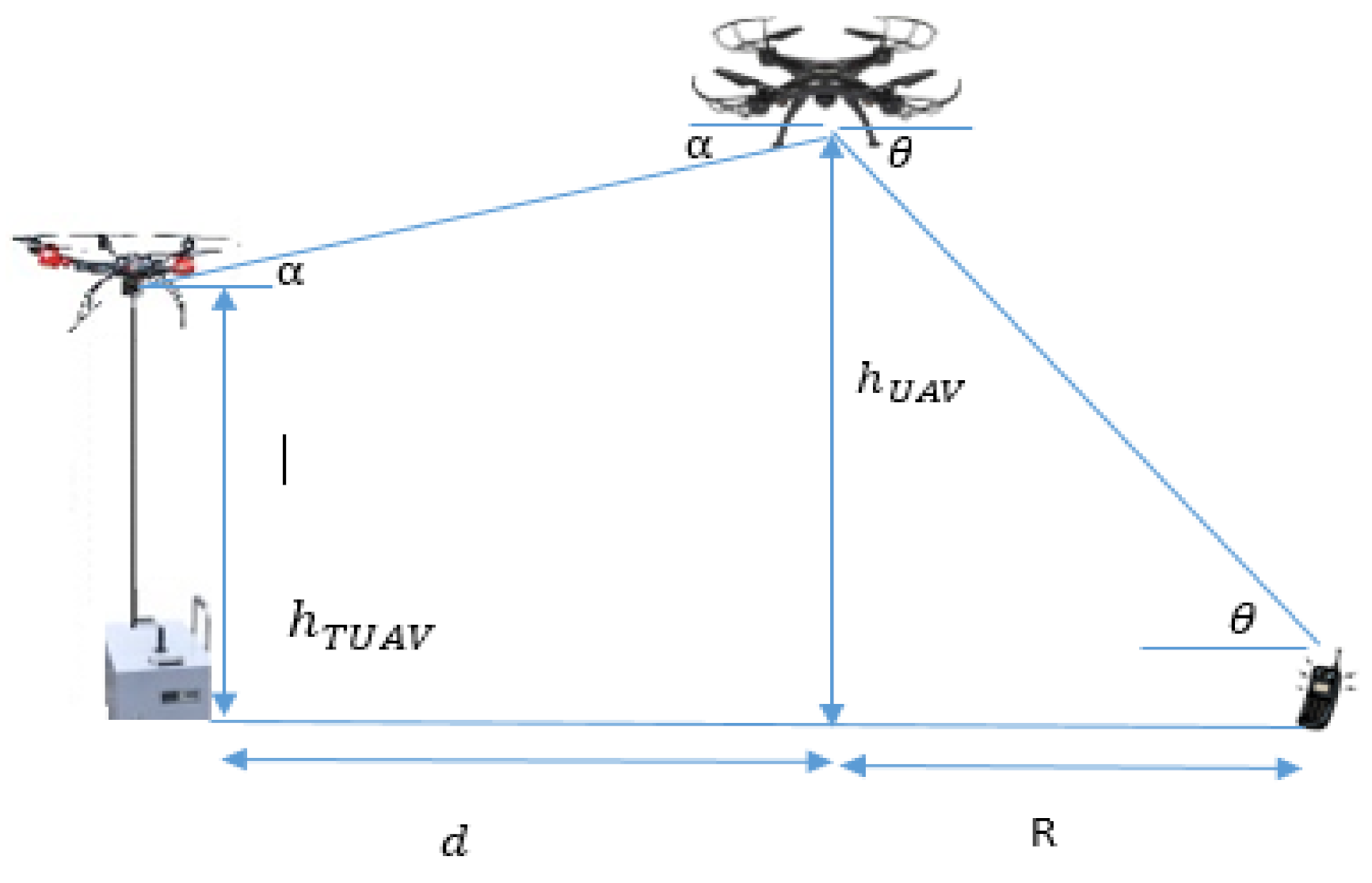
  • Proposing a new relay system TU2U2G system. It uses the TUAV as a viable alternative to replace a BS and provide seamless service over a cable that simultaneously supplies a stable power and a reliable wired data-link connection from a ground control station [3]. Compared to the BS, TUAV improves the system coverage due to its high altitude. Also, it overcomes antenna down-tilting, which increases the path loss between the BS and the UAV in the cellular system [26].
  • Formulating the optimization problem to maximize UAV relay station coverage under the power budget and maximum UAV height constraints. For simplicity, the 3D placement of the UAV is decoupled to the vertical and horizontal placement. Then, a 3D placement algorithm for the system is proposed.
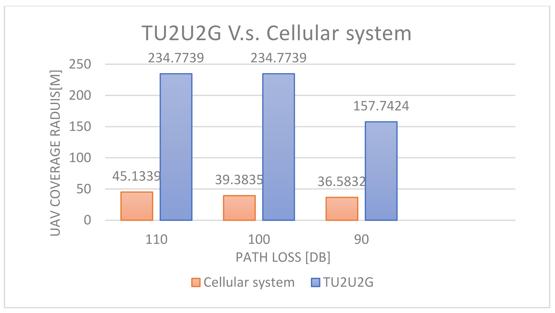
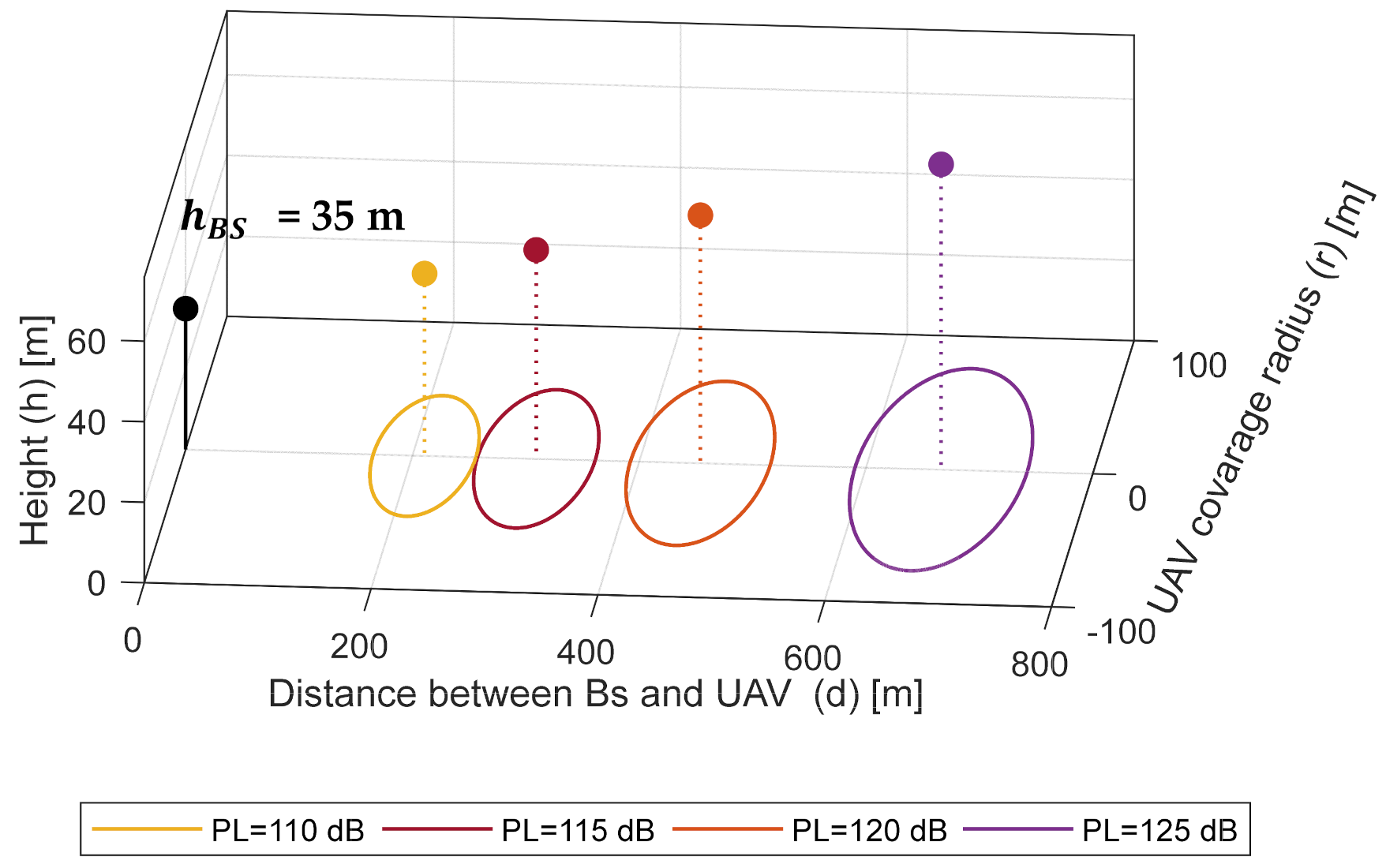
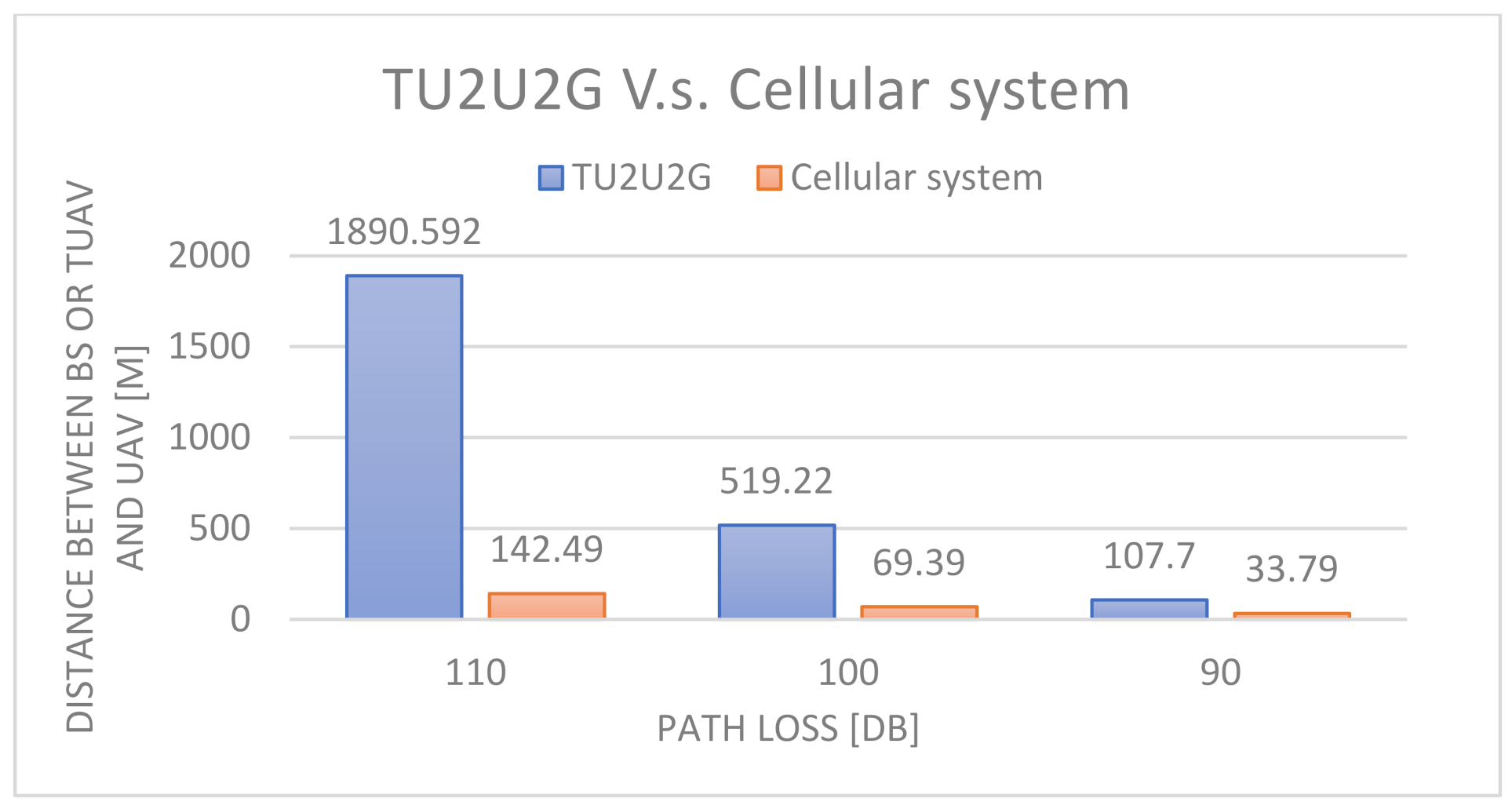
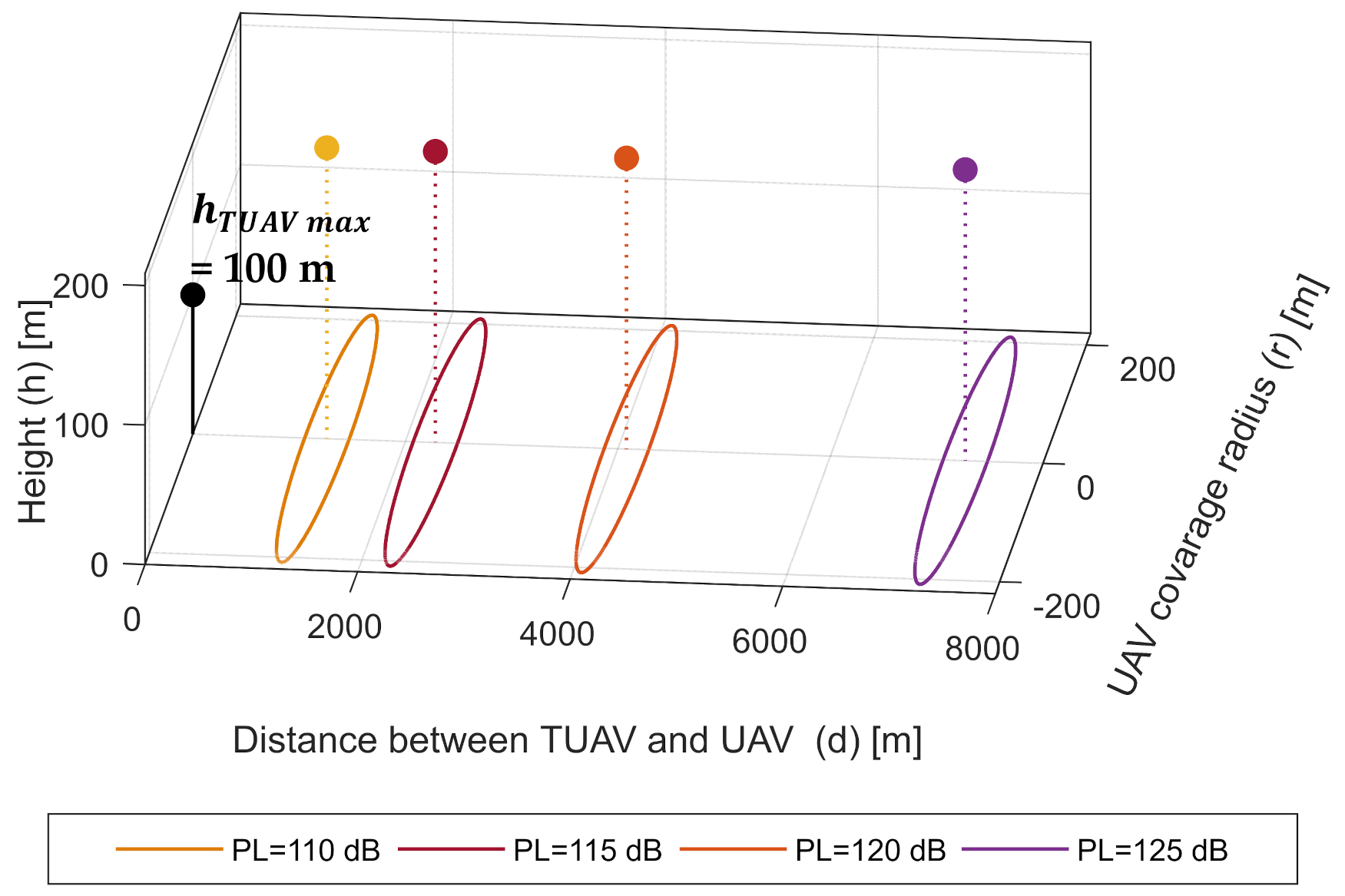
  • Numerical results are presented. TU2U2G the system shows better results than the cellular system in terms of optimum UAV height, maximum coverage radius, and maximum distance between the BS and the UAV.
The structure of the paper is organized as follows: Section 2 presents the system models. The 3D placement of UAV for maximum coverage is proposed in Section 3. Numerical results are discussed in Section 4. Finally, concluding remarks are in Section 5.

2. System Models

The proposed TU2U2G system consists of a TUAV, a UAV, and a MS. The ground distance between the UAV and the MS is R, and θ is the elevation angle. The ground distance between the ground TUAV and the UAV is d, and α is the elevation angle. The TU2U2G communication links are the A2G link and the TU2U link. The A2G link is between the UAV and the MS. The TU2U link is between the TUAV and the UAV as shown in Figure 3. The UAV acts as an aerial base station or a relay to extend wireless coverage. To formulate the optimization problem, it is essential to adopt the appropriate path loss models for the systems communication links.

2.1. Channels Models

2.1.1. A2G Channel

The A2G path loss can be calculated by [10]:
P L A 2 G = F S P L + η ξ
FSPL represents the free space path loss between the UAV and a ground receiver. η ξ refers to LOS and NLOS excess path loss.
F S P L = 20 log ( 4 π f d C )
where f is the frequency; d is the distance between transmitter and receiver, and C is the speed of the light.
The value of η ξ depends on the environment types [10]. It can be calculated by
η ξ = η LOS   P L O S ( θ ) + η NLOS ( 1 P L O S ( θ ) )
where η L O S and η N L O S are the mean excess path loss in case of LOS and NLOS, respectively, and P L O S ( θ ) is the probability of having a LOS connection between the ground user and a UAV in terms of elevation angle is given by [10]:
P L O S ( θ ) = 1 1 + a A 2 G e ( b A 2 G [ θ a A 2 G ] )
where a and b are constants that depend on the environment [10], and θ is the elevation angle. Total path loss of the A2G link is presented in (5) by substituting with (2), (3) and (4) in (1).
P L ( R   , θ ) = A 1 + a A 2 G e ( b A 2 G [ θ a A 2 G ] ) + 20 log ( R sec ( θ ) ) + B
where A = η LOS   η NLOS , and   B = 20   log ( 4 π f C ) +   η NLOS , and d = R sec ( θ ) , R is the ground distance between the transmitter and the receiver

2.1.2. U2U Channel

The TU2U path loss can be represented by a simple free-space propagation model. The free space path loss (FSPL) depends on the frequency and the distance between the transmitter and the receiver. The log-distance equation of FSPL is presented in (6)
P L T U 2 U = 20 log ( L ) + 20 log ( f ) 147.55
where (L) is the distance in meters, (f) is the frequency in (Hz), and 147.55   is 20 log ( 4 π C ) where C is the speed of light. The distance (L) in (6) can be represented as a function of the ground distance between TUAV and UAV ( d T U 2 U ) and elevation angle as in (7).
P L T U 2 U ( d T U 2 U , α ) = 147.55 + 20   log ( f ) + 20 log ( d T U 2 U ) 20 log cos ( α )

2.2. UAV Transmission Power, SNR, and Probability of Coverage

The transmit power P T r of UAV can be written as
P T r = P R x + P L
where P R x is the received power (in dBm).   P L is the path loss.
Therefore, the downlink SNR in dB is calculated as
S N R = P T r P L σ 2
where σ 2 is noise power. The coverage probability is the probability that a user can achieve SNR above the threshold (T). Therefore, the user coverage probability can be defined as
P c = P ( S N R > T )
Besides the SNR-based coverage approach, the coverage can be defined through path loss [6,9].
S N R > T
P T r P L σ 2 > T
P L < P T r T A 2 G σ 2
P L < P L t h
Herein, a user is considered to be covered by the UAV if P L A 2 G < P L t h ( A 2 G ) . Therefore, the UAV coverage radius can be mathematically defined as R | P L A 2 G = P L t h ( A 2 G ) . It means that users at distance R will have the same path loss P L t h ( A 2 G ) , while users with a radius less than R will experience path loss less than P L t h ( A 2 G ) .
In the TU2U2G system, a UAV is considered to be inside the TUAV circular coverage if P L T U 2 U < P L t h ( T U 2 U ) . Therefore, the TUAV coverage radius can be mathematically defined as d T U 2 U | P L T U 2 U = P L t h ( T U 2 U ) .

2.3. Problem Formulation

In this paper, coverage is maximized by jointly optimizing the coverage radius of UAV (R) and the distance between the TUAV and UAV ( d T U 2 U ). In other words, our target is to find optimum R and   d T U 2 U under the power budget and maximum UAV height constraints, as shown in Figure 4. Then, the number of covered users (N) per UAV, with coverage radius R, is maximized by scanning the circumference of a circle whose center is the TUAV and whose radius is   d T U 2 U , as shown in Figure 5.
The problem is formally written as follows:
max N , β i , x i , x U , h U A V , h T U A V N
Subject to constraints:
C 1 :   S N R A 2 G > T
C 2 :   S N R T u 2 U > T
C 3 :   P T r ( A 2 G ) P m a x
C 4 :   P T r ( T U 2 U ) P m a x
C 5 :   h U A V m i n h U A V h U A V m a x
C 6 :   h T U A V m i n h T U A V h T U A V m a x
C 7 : ( x U x T U ) 2 + ( y U y T U ) 2 d T U 2 U 2
C 8 :   ( x i x U ) 2 + ( y i y U ) 2 R 2 + M ( 1 β i )       i I
We aim to maximize the number of users (N) covered by a UAV in (15) under the constraints of transmit power and UAV height. C1 ensures that the user-received SNR will be greater than the SNR threshold T A 2 G .Therefore, the user is considered to be inside the UAV coverage. C2 imposes that UAV-received SNR should be greater than the SNR threshold T T U 2 U for considering that the UAV is inside the TUAV coverage. C3 assures that the user power is not greater than the maximum allowable transmission power. C4 assures that the TUAV power is not be greater than the maximum allowable transmission power. C5 implies that the UAV altitude must be within the region [ h U A V m i n   ; h U A V m a x ] . C6 implies that the UAV altitude must be within the region   [ h T U A V m i n ;   h T U A V m a x ] . C7 imposes that the UAV is inside the TUAV coverage when located within the distance d T U 2 U from the TUAV center   ( x T U , y T U ) . C8 ensures that the user is inside the UAV coverage when located within distance R from the UAV center   ( x U , y U ) . Herein, β     { 0 , 1 } is a binary decision variable such that β = 1 when the user is inside the UAV coverage region, and β = 0 otherwise; M is a large constant to satisfy C8 when β = 0.

3. The Proposed 3D Placement of UAV

It can be noticed that the UAV height is a joint variable between the constrains equations of each optimization problem. Therefore, the 3D placement of the UAV is decoupled to the vertical and horizontal placement for simplicity. First, the vertical placement aims to find the optimum UAV heights for the maximum coverage radius. Since the coverage area of a UAV is considered a circular disc, the horizontal placement aims to find the center of the circular disc.

3.1. Altitude Optimization for Maximum Coverage

In the case of the TU2U2G system, the optimum height of the UAV is constrained by the maximum allowable path losses of the A2G link and TU2U link. Therefore, in the following, the optimum UAV height for each communication link is separately obtained. Then, the final optimum UAV height for each system is obtained using the proposed algorithm.

3.1.1. Finding the UAV Height for Maximum Coverage Radius between UAV and Ground User

The optimal altitude that results in the maximum coverage region can be found by the first derivative R θ = 0 . The optimal elevation angle θ O P T depends on the type of environment [10]. The radius of the coverage area at θ O P T can be calculated from (5).The h U A V that maximizes the coverage region is given by (25).
arg   max θ   P L A 2 G ( h U A V , θ ) = { θ O P T :   π t a n ( θ O P T ) 9 ln ( 10 ) + a A 2 G b A 2 G A e ( b A 2 G [ θ O P T a A 2 G ] ) [ 1 + a A 2 G e ( b A 2 G [ θ O P T a A 2 G ] ) ] 2 = 0 }
Proof of Appendix A.
h U A V = R tan ( θ ) + h m s

3.1.2. Finding the UAV Height for Maximum Distance between TUAV and UAV

For a maximum allowable path loss between TUAV and UAV, the optimum angle α O P T that maximizes d T U 2 U can be calculated from (27). The value of α O P T which means that the maximum distance between TUAV and UAV is achieved when they are at the same level. The maximum distance of d T U 2 U at α O P T can be calculated by (7). Then, the optimum altitude difference between TUAV and UAV (∆h) is obtained by (27).
arg m a x α P L T U 2 U ( h T U A V , h U A V , α ) = { α O P T = 0 }
Proof of Appendix B.
h = d T U 2 U tan ( α )

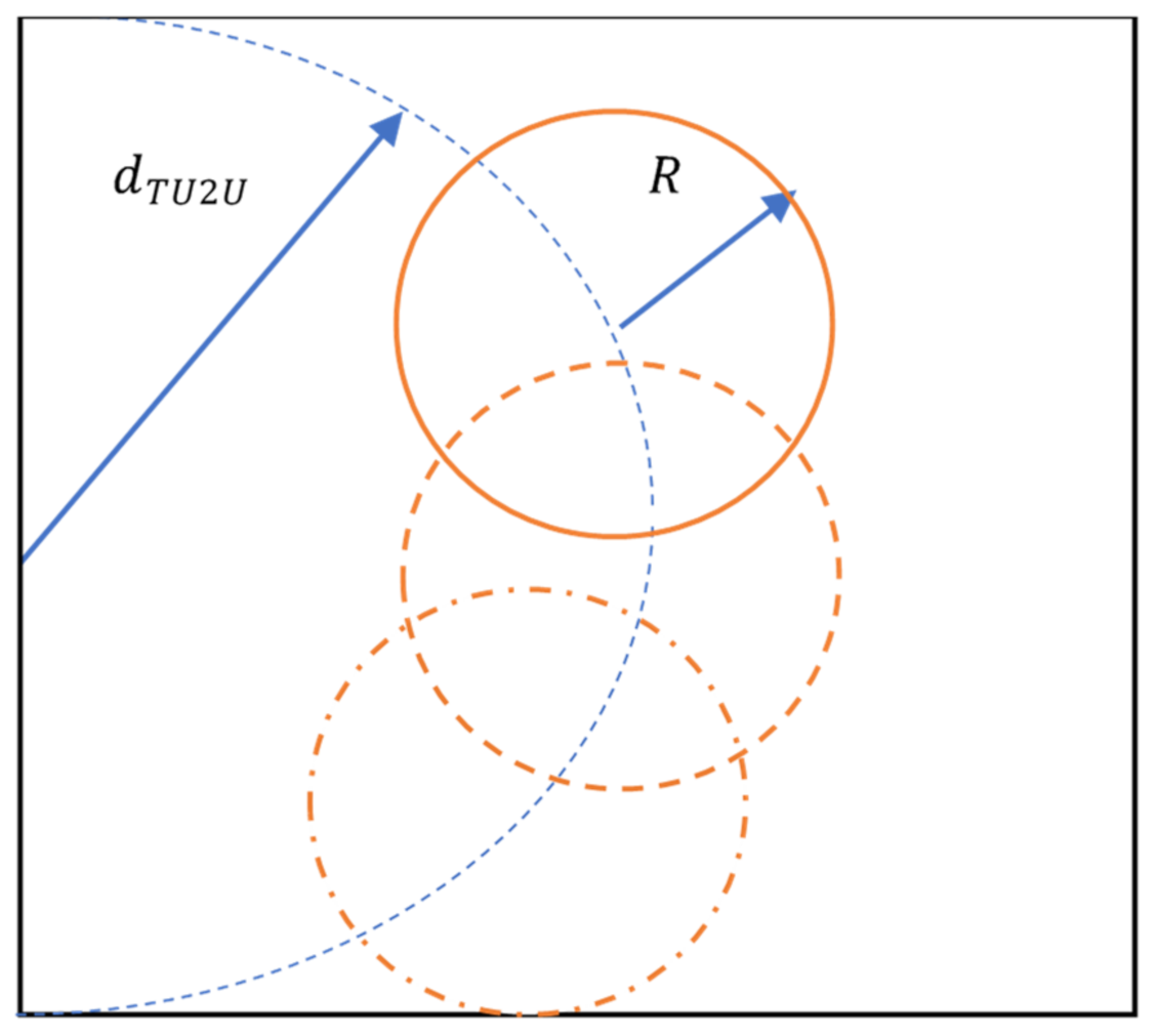
3.2. Horizontal Placement of UAV

The proposed horizontal placement aims to maximize the possible number of enclosed users considering the maximum allowable distance of d T U 2 U . This is done by searching for the center of the coverage region under constraints C7 and C8. C7 ensures that the UAV is inside the TUAV coverage when located within distance d T U 2 U from the TUAV center, while C8 ensures that the user is inside the UAV coverage when located within distance R from the UAV center.

3.3. 3D Placement Algorithm

In the proposed Algorithm 1, step (1) obtains the optimum h UAV for maximum coverage radius R under constraint C1. It is calculated from A2G path loss by finding θ O P T which is obtained by solving the problem in (24). Then, substituting by θ O P T in (5) to calculate R . Then, substituting by θ O P T and R in (25) to calculate h U A V .
Step (2) obtains the optimum h for maximum distance between UAV and TUAV under constraint C2. It is calculated from U2U path loss by finding α OPT which is obtained by solving the problem in (26). Then, substituting by α OPT in (7) to calculate d T U 2 U . Then, substituting by α OPT and d TU 2 U in (27) to calculate h .
Step (3) calculates h U A V and   h T U A V to satisfy the constraints C3 and C4. First, the maximum altitude difference between TUAV and UAV ( h m a x ) is calculated by:
h m a x     = h U A V h T U A V m a x
where h T U A V m a x is the maximum altitude of TUAV. Then, the optimum of h U A V and   h T U A V are found under the constraints of maximum and allowable height.
In Steps (4), (5), R and d T U 2 U are calculated for the new h U A V and   h T U A V from (25) and (27) respectively.
Step (6) solves the problem (15) under constraints C7 and C8 to find the UAV horizontal placement. This is done by searching for the coverage region center ( x U , y U ) that maximizes the number of users (N). It is solved by the branch and cut method [9].
Algorithm 1: Obtain Optimal 3D Location (d, R, h T U A V , h U A V )
Input:   a A 2 G , b A 2 G , θ o p t , η L O S , η N L O S , h T U A V m a x , f,   P U A V T x , P T U A V R x , P M S R x
Output: (d,R, h U A V , h T U A V )
1 Obtain h U A V
Finding θ O P T by solving the problem in (24).
Then, substituting by θ O P T in (5) to calculate R .
Then, substituting by θ O P T and R in (25) to calculate h U A V .
2 Obtain h  
Finding α O P T by solving the problem in (26).
Then, substituting by α O P T in (7) to calculate d T U 2 U .
Then, substituting by α O P T and d T U 2 U in (27) to calculate h .
3 Calculate h m a x = absolute value of ( h U A V h T U A V m a x )
If ( h > ∆ h m a x ) then
∆h = ∆ h m a x
     h T U A V = h T U A V m a x
else
    ∆h = ∆ h
If (   h U A V  > h B ) then
If ( h m a x = 0) then
     h T U A V = h U A V
else
     h U A V = h T U A V m a x + ∆ h
       h T U A V = h T U A V m a x
end If
else
     h T U A V = h U A V + ∆ h
end If
end If
4 ObtainR from (25)
5 Obtaind from (27)
6 Solve a problem: obtain UAV coverage center ( x U , y U ) and users’ coverage N by solving the problem (15)
The worst-case complexity of the proposed algorithm is analyzed as follows. The complexity of Steps 1 to 5 is   O ( n ) ; Step 6, which implements the branch and cut method, is O ( 2 n ) , and each branching node complexity is O ( n 3.5 log ( ε 1 ) ) , where ε is the accepted duality gap. Therefore, the complexity of the algorithms is   O ( n + 2 n n 3.5 log ( ε 1 ) ) .

4. Numerical Results

In this section, numerical results of UAV placement for the TU2U2G system are presented. The optimum values of the distance between TUAV and UAV, and distance between BS and UAV, and the coverage Radius of the UAV are discussed. In addition to that, a comparison between the TU2U2G and cellular systems is presented. The system simulation parameters including environment type, frequency, A2G, and TU2U path loss parameters are listed in Table 2.
The UAV placement in the TU2U2G system is compared with the UAV placement in [10]. The placement in [10] uses the same method as in [6,7,8,9,10] to maximize coverage by finding the optimum UAV height. Also, the power constraints of the communication link between UAV and the cellular BS are applied by using the cellular to UAV (C2U) path loss model in [26]. Then, the Simulations are performed at different allowable path losses. Figure 6 shows that, at the same allowable path loss, the distance between TUAV and UAV in the TU2U2G system is greater than the distance between BS and UAV in the cellular system which can be explained by the following. In the case of the cellular system, the channel between cellular BS and the UAV will be affected by excess path loss due to the low height of the cellular BS and antenna down tilting [26]. However, the channel between TUAV and UAV will have better LOS condition due to TUAV high altitude. Also, the coverage radius of the UAV in the TU2U2G system is greater than the cellular system as shown in Figure 7 which can be explained by the following. In the TU2U2G, the TUAV high altitude enables the relay UAV to achieve the optimum attitude which maximizes the UAV coverage. Therefore, the TU2U2G system can extend the coverage better than the cellular system.
Figure 8 and Figure 9 show the 3D placement for the TU2U2G system and the cellular system respectively. The simulation is done at The A2G path loss = 100 dB. While TU2U is set to different Path loss values 110 dB, 115 dB, 120 dB, and 125 dB. The optimum altitude of the A2G link for PL = 100 dB is 225.9 m and the coverage radius is 208.7 m. In the TU2U2G system, using TUAV allows the UAV to reach the optimum altitude of the A2G link. However, in the cellular system, the maximum coverage of the UAV is 70 m. Figure 10 shows the increase of UAV height and coverage with the increase of the TUAV height. On the other hand, the antenna down tilting and the low height of the Base station limit the UAV height to a max of 70 m which reduces the coverage radius of the UAV.

5. Conclusions

A new relay system, TU2U2G, that replaces a BS with a TUAV is proposed. Compared to the cellular BS, the TUAV improves system coverage due to its high altitude. In addition to that, it overcomes the antenna down-tilting, which increases the path loss between the BS and the UAV in the cellular system. An optimization problem to maximize UAV relay station coverage under the power budget and maximum UAV height constraints is formulated. The 3D placement of the UAV is decoupled to the vertical and horizontal placement. Then, a 3D placement algorithm for the system is proposed. The TU2U2G system shows better results than the cellular system in terms of optimum UAV height, maximum coverage radius, and maximum relaying distance between the TUAV and the UAV.
The research in the analysis and design of TUAV-enabled communication systems is still at an early stage. Therefore, there are many potential extensions for this work. For instance, the placement of UAVs for throughput maximization should be investigated. In addition to that, the study of the deployment of multi-TUAVs considering co-channel interference is another potential extension for this work.

Author Contributions

Conceptualization, methodology, formal analysis, data curation, writing—original draft preparation, and writing—review and editing, N.E.-D.S.; supervision, I.M.H. and F.N. All authors have read and agreed to the published version of the manuscript.

Funding

This research received no external funding.

Conflicts of Interest

The authors declare no conflict of interest.

Appendix A

The optimum height of UAV ( h ) for maximum coverage radius ( R ) can be found by differentiating R with respect to h ( R h ) = R θ θ h = 0 . Since θ h =   t a n 1 ( h R ) h = R R 2 + h 2 > 1 , then optimum altitude can be achieved by searching for the optimum elevation angle α O P T that maximizes ( R ). It is calculated by the first derivative
R θ = 0
π t a n ( θ O P T ) 9 ln ( 10 ) + a A 2 G b A 2 G A e ( b A 2 G [ θ O P T a A 2 G ] ) [ 1 + a A 2 G e ( b A 2 G [ θ O P T a A 2 G ] ) ] 2 = 0

Appendix B

The maximum distance between a TUAV and a UAV ( d T U 2 U ) can be found by differentiating d T U 2 U with respect to h ( d T U 2 U ( h ) ) = d T U 2 U α α ( h ) = 0 . Since α ( h ) = t a n 1 ( h d ) ( h ) = d T U 2 U d T U 2 U 2 + h 2 > 1 , then the optimum altitude can be achieved by searching for the optimum elevation angle α O P T that maximizes ( d T U 2 U ). It is calculated by the first derivative (7) with respect to α
d T U 2 U α = 0
d T U 2 U α = π tan ( α O P T ) 9 ln ( 10 ) = 0

References

  1. Zeng, Y.; Zhang, R.; Lim, T.J. Wireless communications with unmanned aerial vehicles: Opportunities and challenges. IEEE Commun. Mag. 2016, 54, 36–42. [Google Scholar] [CrossRef] [Green Version]
  2. Merwaday, A.; Guvenc, I. UAV assisted heterogeneous networks for public safety communications. In Proceedings of the 2015 IEEE Wireless Communications and Networking Conference Workshops (WCNCW), New Orleans, LA, USA, 9–12 March 2015; pp. 329–334. [Google Scholar]
  3. Kishk, M.; Bader, A.; Alouini, M.-S. Aerial Base Station Deployment in 6G Cellular Networks Using Tethered Drones: The Mobility and Endurance Tradeoff. IEEE Veh. Technol. Mag. 2020, 15, 103–111. [Google Scholar] [CrossRef]
  4. Kishk, M.A.; Bader, A.; Alouini, M.-S. On the 3-D Placement of Airborne Base Stations Using Tethered UAVs. IEEE Trans. Commun. 2020, 68, 5202–5215. [Google Scholar] [CrossRef]
  5. AT&T. AT&T’s First Official Deployment of Cell on Wings in Puerto Rico. 2017. Available online: https://www.youtube.com/watch?v=RgxVHbQaMIE (accessed on 14 January 2022).
  6. Shakoor, S.; Kaleem, Z.; Do, D.-T.; Dobre, O.A.; Jamalipour, A. Joint Optimization of UAV 3-D Placement and Path-Loss Factor for Energy-Efficient Maximal Coverage. IEEE Internet Things J. 2021, 8, 9776–9786. [Google Scholar] [CrossRef]
  7. Cui, J.; Shakhatreh, H.; Hu, B.; Chen, S.; Wang, C. Power-Efficient Deployment of a UAV for Emergency Indoor Wireless Coverage. IEEE Access 2018, 6, 73200–73209. [Google Scholar] [CrossRef]
  8. Alzenad, M.; El-Keyi, A.; Lagum, F.; Yanikomeroglu, H. 3-D Placement of an Unmanned Aerial Vehicle Base Station (UAV-BS) for Energy-Efficient Maximal Coverage. IEEE Wirel. Commun. Lett. 2017, 6, 434–437. [Google Scholar] [CrossRef] [Green Version]
  9. Alzenad, M.; El-Keyi, A.; Yanikomeroglu, H. 3-D Placement of an Unmanned Aerial Vehicle Base Station for Maximum Coverage of Users With Different QoS Requirements. IEEE Wirel. Commun. Lett. 2017, 7, 38–41. [Google Scholar] [CrossRef] [Green Version]
  10. Al-Hourani, A.; Kandeepan, S.; Lardner, S. Optimal LAP Altitude for Maximum Coverage. IEEE Wirel. Commun. Lett. 2014, 3, 569–572. [Google Scholar] [CrossRef] [Green Version]
  11. Sun, Y.; Xu, D.; Ng, D.W.K.; Dai, L.; Schober, R. Optimal 3D-Trajectory Design and Resource Allocation for Solar-Powered UAV Communication Systems. IEEE Trans. Commun. 2019, 67, 4281–4298. [Google Scholar] [CrossRef] [Green Version]
  12. Wang, H.; Ren, G.; Chen, J.; Ding, G.; Yang, Y. Unmanned Aerial Vehicle-Aided Communications: Joint Transmit Power and Trajectory Optimization. IEEE Wirel. Commun. Lett. 2018, 7, 522–525. [Google Scholar] [CrossRef] [Green Version]
  13. Wu, Q.; Zeng, Y.; Zhang, R. Joint Trajectory and Communication Design for Multi-UAV Enabled Wireless Networks. IEEE Trans. Wirel. Commun. 2018, 17, 2109–2121. [Google Scholar] [CrossRef] [Green Version]
  14. Cai, Y.; Wei, Z.; Li, R.; Ng, D.W.K.; Yuan, J. Joint Trajectory and Resource Allocation Design for Energy-Efficient Secure UAV Communication Systems. IEEE Trans. Commun. 2020, 68, 4536–4553. [Google Scholar] [CrossRef] [Green Version]
  15. El Hammouti, H.; Benjillali, M.; Shihada, B.; Alouini, M.-S. Learn-As-You-Fly: A Distributed Algorithm for Joint 3D Placement and User Association in Multi-UAVs Networks. IEEE Trans. Wirel. Commun. 2019, 18, 5831–5844. [Google Scholar] [CrossRef] [Green Version]
  16. Huang, M.; Huang, L.; Zhong, S.; Zhang, P. UAV-Mounted Mobile Base Station Placement via Sparse Recovery. IEEE Access 2020, 8, 71775–71781. [Google Scholar] [CrossRef]
  17. Zhang, J.; Liang, F.; Li, B.; Yang, Z.; Wu, Y.; Zhu, H. Placement optimization of caching UAV-assisted mobile relay maritime communication. China Commun. 2020, 17, 209–219. [Google Scholar] [CrossRef]
  18. Li, Y.; Feng, G.; Ghasemiahmadi, M.; Cai, L. Power Allocation and 3-D Placement for Floating Relay Supporting Indoor Communications. IEEE Trans. Mob. Comput. 2019, 18, 618–631. [Google Scholar] [CrossRef]
  19. Chen, J.; Gesbert, D. Optimal positioning of flying relays for wireless networks: A LOS map approach. In Proceedings of the 2017 IEEE International Conference on Communications (ICC), Paris, France, 21–25 May 2017; pp. 1–6. [Google Scholar]
  20. Larsen, E.; Landmark, L.; Kure, O. Optimal UAV relay positions in multi-rate networks. In 2017 Wireless Days; IEEE: Port, Portugal, 2017; pp. 8–14. [Google Scholar]
  21. Zeng, Y.; Zhang, R.; Lim, T.J. Throughput Maximization for UAV-Enabled Mobile Relaying Systems. IEEE Trans. Commun. 2016, 64, 4983–4996. [Google Scholar] [CrossRef]
  22. Kalantari, E.; Bor-Yaliniz, I.; Yongacoglu, A.; Yanikomeroglu, H. User association and bandwidth allocation for terrestrial and aerial base stations with backhaul considerations. In Proceedings of the 28th IEEE Annual International Symposium on Personal, Indoor and Mobile Radio Communications (PIMRC), Montreal, QC, Canada, 8–13 October 2017. [Google Scholar]
  23. Chattopadhyay, A.; Ghosh, A.; Kumar, A. Asynchronous Stochastic Approximation Based Learning Algorithms for As-You-Go Deployment of Wireless Relay Networks Along a Line. IEEE Trans. Mob. Comput. 2017, 17, 1004–1018. [Google Scholar] [CrossRef] [Green Version]
  24. Chen, Y.; Feng, W.; Zheng, G. Optimum Placement of UAV as Relays. IEEE Commun. Lett. 2018, 22, 248–251. [Google Scholar] [CrossRef] [Green Version]
  25. Sharma, V.; Sabatini, R.; Ramasamy, S. UAVs Assisted Delay Optimization in Heterogeneous Wireless Networks. IEEE Commun. Lett. 2016, 20, 2526–2529. [Google Scholar] [CrossRef]
  26. Al-Hourani, A.; Gomez, K. Modeling Cellular-to-UAV Path-Loss for Suburban Environments. IEEE Wirel. Commun. Lett. 2017, 7, 82–85. [Google Scholar] [CrossRef]
Figure 1. TUAV station components.
Electronics 11 00385 g001
Figure 2. Cellular BS versus UAV versus TUAV.
Electronics 11 00385 g002
Figure 3. The TU2U2G system.
Electronics 11 00385 g003
Figure 4. Relay distance ( d T U 2 U ) and coverage radius (R).
Electronics 11 00385 g004
Figure 5. UAV horizontal placement.
Electronics 11 00385 g005
Figure 6. Distance between BS and UAV and distance between TUAV and UAV at different path loss values.
Electronics 11 00385 g006
Figure 7. Coverage radius of the UAV for a TU2U2G’s and a cellular system’s different path loss values.
Electronics 11 00385 g007
Figure 8. 3D placement of a UAV for TU2U2G system at different path losses.
Electronics 11 00385 g008
Figure 9. 3D placement of a UAV for cellular system at different path losses.
Electronics 11 00385 g009
Figure 10. TUAV height versus UAV height and coverage.
Electronics 11 00385 g010
Table 1. Related work on UAV placement pros and cons.
Ref No.UAV Placement forProsCons
[6]Coverage maximizationJointly optimizes the 3D UAV placement and path loss compensation factorReferences [6,7,8,9,10,11,12,13,14,15,16] consider only the power constraints of the communication link between UAV and the ground user mobile station (MS) but do not consider the power constraints of the communication link between a UAV and the BS
[7]Minimizes the total transmit power required to provide wireless coverage for indoor users
[8]Maximizes the number of covered users with minimum transmission power
[9]Maximizes the number of served users with different quality-of-service requirements
[10]finds the optimum UAV altitude
[11]Throughput maximizationA joint trajectory and resource allocation algorithm
[12]A joint transmit power and trajectory optimization algorithm
[13]Optimizing the scheduling of multi-user communication and association jointly with the trajectory of UAVs and power control
[14]Joint optimization of Trajectory and resource allocation
[15]Algorithm for downlink sum-rate maximization
[16]Algorithm for UAV placement based on sparse recovery
[17]Throughput maximizationMaximizes the average achievable rate through the one-dimensional linear searchReferences [17,18,19,20,21,22,23,24,25] are proposed for UAVs to assist the cellular network. However, the antenna down-tilting and low height of the cellular base station (BS) limits the ability of the UAV relay station to reach high altitudes due to the power constraint on the path between a UAV and a BS.
[18]The optimization problem is formulated to maximize the system throughput.
[19]An algorithm to find the UAV optimal position based on LOS information
[20]Explores the relationship between system throughput and placement of a UAV
[21]Jointly optimizes throughput and the UAV’s trajectory
[22]Sum logarithmic rate of the users maximizeAn algorithm to find the 3D locations of UAVs besides the user-BS associations and bandwidth allocations of the wireless backhaul
[23]Data rate maximizationAlgorithms for deploying a multi-relay network to maximize the end-to-end achievable rate
[24]Power loss, outage probability, and BER minimizationAn approach to find the optimum altitude of UAV
[25]Optimizing the overall network delaysAn approach to optimize the overall network delays
Table 2. The system simulation parameters.
ParameterValue
Environment typeDense Urban
frequency2 GHz
A2G path loss parameters η L O S  [10]1.6
η N L O S  [10]23
A2G path loss100 dB
TU2U path loss parameters h T U A V m a x  [4]100
TU2U path loss110 dB, 115 dB, 120 dB
Publisher’s Note: MDPI stays neutral with regard to jurisdictional claims in published maps and institutional affiliations.

