Abstract
Subcarrier Index Modulation is an OFDM variant that provides superior power and bandwidth efficiency. In this paper, we present a novel, double-sided pulse interval modulation (DS-PIM)-based SIM OFDM technique. The proposed technique exploits the variable symbol size of DPIM to provide a variable sub-block size and enable dynamic assignment of subcarriers rather than the fixed size of conventional SIM OFDM. In comparison with conventional Subcarrier Index-Modulated OFDM (SIM-OFDM), the proposed approach shows a 12.5% reduction in bandwidth usage for a 2-bit index word. On average, 3.5 subcarriers are employed by the proposed technique per sub-block, in comparison with 4 subcarriers for the conventional technique. The proposed technique provides a superior spectral efficiency compared with conventional SIM-OFDM, even for higher-order modulation.
1. Introduction
The term LiFi was first coined by Prof. Harald Haas in one of his TED talks, in 2011. The technique has since, attracted a lot of research interest and is maturing very fast. The idea behind LiFi is to take advantage of the vast deployment of LED lights for illumination, and to use them to carry data, simultaneously. LiFi proposes fast modulation of LEDs to ensure that the flicker is undetectable to the naked eye, providing both illumination and communication at the same time. The advantages of LiFi range from higher security and larger bandwidth to better power efficiency [1]. Despite the benefits, LiFi comes with its own set of challenges such as flicker mitigation, dimming control, ambient light interference, and the low switching speed of typical LEDs used for illumination [2]. Some of these challenges have prompted research to switch from single-carrier to multicarrier modulation.
Orthogonal Frequency Division Multiplexing (OFDM) is a well-known digital communication technique and has been around for many years. It has found great use in visible light communication (VLC) [3]. OFDM provides a superior bandwidth performance, along with good flicker mitigation properties. Since a low-cost implementation is desired, intensity modulation and direct detection (IM/DD) are our techniques of choice, meaning the modulated signals should be non-negative and real-valued [4]. Several OFDM variants have been proposed to satisfy these constraints [5,6,7,8,9] such as pulse amplitude-modulated digital multi-tone (PAM-DMT), asymmetrically clipped optical OFDM (ACO-OFDM), DC-biased optical OFDM (DCO-OFDM), Unipolar OFDM and Flip OFDM. To ensure the signals are real-valued, Hermitian symmetry is used on the subcarriers. A DC bias may be imposed on the signals to make them non-negative. Alternate arrangements in the time and frequency domain, are used on signals to ensure non-negativity without the need for DC bias in [5,6,7,8,9]. These arrangements, however, result in a loss of spectral efficiency. Hybrid approaches [10,11,12,13], such as asymmetrically clipped DC-biased optical OFDM (ADO-OFDM), hybrid ACO-OFDM, layered ACO-OFDM (LACO-OFDM) and enhanced U-OFDM have been proposed to overcome this loss of spectral efficiency. A detailed discussion of index modulation techniques is presented in [14], where time domain, space domain and frequency domain index modulation were discussed in detail. Transmitter and receiver models and a detailed error rate analysis for each approach is presented in detail [14]. The authors in [15] discuss the implementation of Index Modulation (IM) in OFDM systems and present their views on the future research direction in this field. The spectral and power efficiencies of DCO-OFDM have been investigated in [16]. The authors have proposed a multilevel mercury-water filling power allocation scheme to improve the spectral efficiency, while a Dinkelback-type power allocation scheme has been proposed to improve the energy efficiency [16].
SIM-OFDM has been proposed in [17], where each subcarrier is turned ON or OFF, carrying one bit of information, while the individual subcarriers are modulated by conventional modulation techniques. This provides better energy efficiency by turning some of the subcarriers OFF, while extra bits are also carried by the indices of the activated (ON) subcarriers. Enhanced SIM-OFDM proposed in [18] pairs two subcarriers together, and only one subcarrier is ON. This further improves power efficiency, but the number of bits transmitted through the indices are reduced by half, providing a poorer spectral efficiency. OFDM with index modulation (OFDM-IM) is proposed in [19], where subcarriers are divided into subgroups and then index modulation is performed within each subgroup. The technique has a much-improved power efficiency; however, the number of inactive subcarriers means wastage of bandwidth. It has also been shown that OFDM-IM outperforms the conventional OFDM with low spectral efficiency only. When higher-order modulations are used to achieve higher spectral efficiency, the performance of OFDM-IM in terms of spectral efficiency is even worse than conventional OFDM [20]. Apart from these SIM-OFDM has also been combined with multiple-input multiple-output (MIMO) systems [21,22], providing considerable performance improvement. A dual-mode index modulation-aided OFDM (DM-OFDM) has been proposed in [23,24]. Here, all subcarriers are utilized to transmit information. The subcarriers are divided into two subgroups, each modulated by two different constellation modes. It has been experimentally demonstrated that SIM-OFDM with digital pre-equalization achieves a much-improved BER compared to classical OFDM [25]. In [26], a variant of SIM OFDM is presented where information is carried in the location of the null subcarrier rather than the active subcarrier location. This approach results in a lower computational complexity. In ref. [27] the authors present a type of SIM OFDM called, time-domain sample index modulation (TIM) to provide efficient dimming control over a wide brightness range, while maintaining a high signal-to-noise ratio (SNR) performance and a high transmission rate. The authors call their approach, indexed dimming (iDim). The results are validated through a hardware implementation on FPGA. A dual-indexing method is presented in [28]. Here, each group is split into subgroups, and only the selected subgroups are activated using the first set of index bits, and then, subcarriers are selected from the activated subgroups using a second set of index bits. The approach has been reported as showing an improved spectral efficiency (SE). A combination of spread spectrum (SS) and SIM-OFDM has been proposed in [29], which enables transmission across three signal domains. SS-SIM-OFDM is shown in [29] to provide better BER performance than conventional OFDM compared to a Rayleigh fading channel. After a comprehensive review of the existing literature on index modulation (IM), the authors of [30] conclude that further research is needed to combine IM with other approaches in order to improve its spectral efficiency. The authors have presented a differential index modulation technique in [31], enabling a variable sub-block size. The authors present an improved spectral efficiency as an advantage over conventional SIM-OFDM, however no results have been presented to quantify this advantage.
The focus of previous work on SIM OFDM has been focused on sub-block sizes. This limits spectral efficiency and compromises flexibility. This paper presents a novel SIM OFDM approach with a variable sub-block size. The proposed scheme provides a superior bandwidth efficiency compared with conventional SIM OFDM techniques, even for higher-order modulation of the subcarriers.
The novel contributions of this research include:
- A novel variant of SIM OFDM that enables the use of variable sub-block size and a dynamic subcarrier assignment instead of a fixed one.
- An improved bandwidth efficiency has been reported, while maintaining a BER performance close to that of conventional SIM OFDM.
- Improved bandwidth efficiency for high order modulation of the subcarriers. This is a concern for conventional SIM OFDM.
2. Principle of Subcarrier Index Modulation OFDM (SIM OFDM)
Subcarrier Index-Modulated OFDM (SIM-OFDM) is a relatively recent addition to the family of OFDM variants [14,15]. In SIM-OFDM, the information is not only modulated onto the subcarrier, but is also carried by the index of the active subcarriers. It provides a tradeoff between spectral efficiency and power efficiency by changing the number of active subcarriers. Figure 1 shows a conventional SIM OFDM transmitter. The data bit stream is divided into P parallel substeams and the total available subcarriers are also divided into P subgroups of size n. The splitter could be simple Time Division Demultiplexer that separates even and odd bits. Each substeam goes to a subgroup creator, where it is further split into two streams. One of these (B1) goes to the index selector and is used to select the subcarriers that are turned on in a particular subgroup. The second stream (B2) is modulated onto the selected subcarriers using conventional modulation techniques (e.g., QAM). The same process happens for each subgroup.
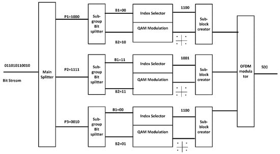
Figure 1.
System block diagram of SIM OFDM transmitter.
Figure 2 shows a closer view of individual sub-block creator. The available subcarriers are divided into several subgroups. The input stream of bits for each subgroup, is split into two substeams. One substeam (B2) is modulated conventionally (e.g., QAM), while the other (B1) is used for index selection.

Figure 2.
Block diagram of SIM OFDM sub-block creator.
Table 1 shows examples of SIM-OFDM implementation, where S1, S2, and S3 are the activated subcarriers corresponding to the index bit.

Table 1.
Subcarrier selection for a 2-bit index data word on B1 using conventional SIM OFDM.
At the receiver end, the incoming OFDM signal is divided into groups of subcarriers of size n. B1 is obtained from the locations of the ON subcarriers. B2 is then obtained by demodulating those subcarriers, and thus the data stream is reconstructed. A functional block diagram of SIM OFDM receiver is given in Figure 3.
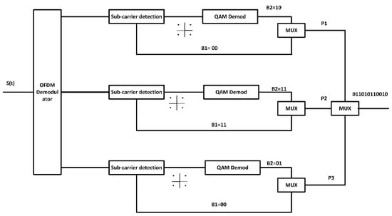
Figure 3.
System block diagram of SIM OFDM receiver.
3. System Model and Proposed Technique
In digital pulse interval modulation (DPIM), data is encoded as a number of discrete time intervals. The symbol length is variable and is determined by the data that is to be modulated. A guard interval may be introduced in order to avoid two adjacent pulses occurring, where the time interval is zero. Table 2 shows a DPIM-modulated signal in comparison with a PPM-modulated signal. The DPIM-modulated signal S(t) can be represented by Equation (1) as [32].
where Tc is the bit duration, while n = 0, 1, 2, 3, … and k = 0, 1, 2, 3, …

Table 2.
Modulation Data Frame PPM, DPIM.
A major advantage of DPIM is high spectral efficiency when compared with PPM due to a variable symbol size. Only the longest symbol has a length equal to a PPM symbol, which can be seen from Table 2. The 2-bit data word and the corresponding DPIM-modulated waveforms are shown in Figure 4a,b, respectively.
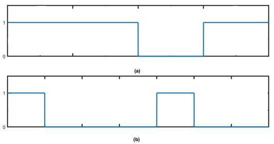
Figure 4.
Waveforms of (a) 2-bit data (b) DPIM-modulated waveform.
DS-PIM-Based SIM OFDM
We propose a novel variant of SIM OFDM for visible light communication. Instead of the fixed sub-block size of conventional SIM OFDM, the proposed approach suggests the implementation of variable block size, using a double-sided PIM (DS-PIM) to modulate B1 before subcarrier selection, thereby improving bandwidth utilization. In the proposed modification, the DPIM symbol shown in Table 2 shall have an added 1 at the end of the symbol as well, ensuring that two subcarriers per sub-block are always turned on. Table 3 shows the DPIM and DS-PIM symbols for two-bit data.

Table 3.
Modulation data frame for data, DPIM and DS-PIM.
The DS-PIM symbol is then used for carrier selection out of a total 5 available sub-blocks from 5 subcarriers, instead of the 4 used for conventional SIM OFDM. The block diagram of the SIM OFDM sub-block creator, based on the proposed approach, is presented in Figure 5.
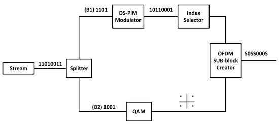
Figure 5.
Block diagram of SIM OFDM sub-block creator, using the proposed technique.
The use of DS-PIM ensures that all 5 subcarriers are not always occupied and may dynamically be assigned to the next sub-block. The ending 1 serves a secondary purpose of indicating the last subcarrier needed by the current sub-block, marking the end of the sub-block and enabling the dynamic assignment of subcarriers. Table 4 shows the possible sub-block sizes for the proposed scheme. The unoccupied subcarriers are represented by F in Table 4 and may be assigned to the next sub-block.

Table 4.
Subcarrier selection for a 2-bit index data word on B1, using the proposed scheme.
A total of 105 bits (8 × 10⁴ on B2 and 2 × 10⁴ on B1) were modulated using DS-PIM-SIM OFDM. The average sub-block size was calculated to be 3.5 instead of 4. This translates to 12.5% less bandwidth usage.
Figure 6 shows all 4 possible locations of ON subcarriers for a 2-bit index word. In a 5-subcarrier block, there is only 1 possible instance when all 5 subcarriers are in use.
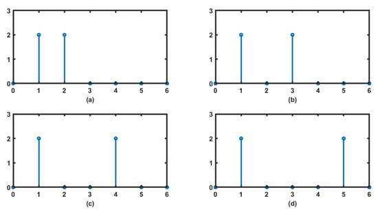
Figure 6.
Locations of ON subcarriers for 2-bit index data word (a) 00 (b) 01 (c) 10 (d) 11.
4. Error Performance Analysis
There are three types of errors that can occur in a DPIM pulse train, these being erasure, false detection and wrong slot error. Erasure occurs when a bit is erased due to attenuation and the received signal falls below the threshold. False detection is the case when a 1 is wrongly detected in place of a zero due to the signal exceeding the threshold due to noise. A wrong slot is when a pulse occupies the wrong time slot due to dispersion. In DPIM, the effect of an error spills over into the next symbol, unlike PPM, where the effect of an error is restricted to the specific symbol. An erasure causes two symbols to merge into one, while a false detection causes a symbol to split into two [32]. The error performance of DPIM is similar to differential PPM (DPPM), the difference being that the wrong slot error is restricted, only to the next symbol, and does not go beyond that used in DPPM [33].
The expression for the probability of error in a DPIM symbol is given by Equation (2) as [32]
where is the threshold, M is the modulation order, while Ts and Ti represent the slot duration and received pulse width, respectively. CNR in Equation (2) stands for carrier-to-noise ratio and may be given by,
where Fb is the bit rate, C is the total carrier power, N is the total noise power and B is the bandwidth.
The three terms in Equation (2) represent the erasure, false detection and wrong slot error. Alternately, Equation (2) may be rewritten as Equation (4) [33]
where is the probability of erasure, is the probability of wrong slot detection, is the probability of false alarm and Lavg is the average symbol length. Unlike in the case of conventional DPIM, the end of a DS-PIM symbol is also marked with a 1 (Table 3), making the wrong slot error less likely. This effect is negligible, especially at higher values of CNR. The error rate of mDPIM may be obtained by rewriting Equation (4) as Equation (5).
where this results in a symbol error rate (SER) that is significantly lower than that of conventional DPIM and close to that of PPM.
Equation (6) gives the probability of two adjoint events.
where P(A) and P(B) represent the probability of the occurrence of event A and B, respectively. in Equation (6) is the probability of both A and B occurring simultaneously. The probability of error in a SIM OFDM symbol is the adjoint probability of error in the index symbol and the probability of error in modulation symbol. This can be shown modifying Equation (6) to obtain Equation (7).
The probability of error in a DS-PIM-SIM OFDM symbol can be given by Equation (8)
where is the symbol error probability in a QAM symbol, while is the probability of error in a DS-PIM symbol.
Probability of symbol error in a QAM symbol has been discussed in detail, and an expression has been derived in [34].
5. Spectral Performance Analysis
The spectral efficiency of a SIM OFDM system can be computed using the total number of bits carried by a sub-block at a given instance and the number of used subcarriers. Equations (9) and (10) represent the spectral efficiency of an SIM OFDM system.
where n is the block size and k represents the number of subcarriers that are turned on. M is the modulation level of the quadrature amplitude modulation (QAM)-modulated subcarriers. In Equation (10), C(n,K) represents the index bits (B1) being carried in a sub-block, while represents the bits that are QAM-modulated onto the subcarriers (B2). n, is the number of subcarriers in a given subgroup. In case of DS-PIM this is replaced by the average number of subcarriers (navg).
6. Simulation Setup
In order to assess the performance of the proposed technique, Matlab simulations have been conducted to compare the error performance as well as bandwidth efficiency of conventional SIM OFDM and DS-PIM-SIM OFDM.
Figure 7 shows the simulation setup used to obtain SER vs CNR curve.
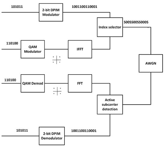
Figure 7.
Simulation setup used to obtain SNR vs CNR curve.
At the transmitter end, two-bit streams are generated. One is modulated using a DS-PIM modulator, while the other is modulated through a QAM modulator. IFFT is then performed on the QAM-modulated bit stream. The resulting QAM symbols are assigned specific indices within the subgroup, corresponding to the indices of 1’s in the DPIM modulated symbol. The signal is then passed through an AWGN noise source.
At the receiver, DPIM symbol detection is achieved by comparing the magnitude of the received signal with a threshold level. DPIM demodulation is then performed to extract the original stream (B1). For the second bit stream (B2), FFT is performed on the symbol at the detected indices and the resulting stream is later QAM-demodulated.
Table 5 contains some of the simulation parameters for the experiment.

Table 5.
Parameters used for Matlab simulation.
7. Results and Discussions
DS-PIM conventional SIM-OFDM exhibits good spectral efficiency for lower-order modulation of B2. However, for higher-order modulation, the bits which were transmitted through the subcarrier indices are not enough to compensate for the loss of subcarriers. Table 6 shows how the contribution of carrier bits increases vs. index bits.

Table 6.
Distribution of bits between B1 and B2.
Figure 8 shows the comparison between conventional and DS-PIM-SIM OFDM for different sub-block sizes versus modulation level M of the modulation bit stream. In this case, the number of active subcarriers are 2 (K = 2). The results show that the proposed scheme gives a much superior bandwidth efficiency when compared with conventional SIM OFDM, for a given sub-block size. Smaller sub-blocks have been shown to have a much larger bandwidth efficiency.
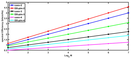
Figure 8.
Spectral Efficiency versus modulation order, for conventional and DS-PIM-based SIM OFDM (index word lengths of 2-bits, 3-bits and 4-bits) where K = 2.
Figure 9 shows the effect of increasing the number of ON subcarriers on spectral efficiency for both conventional and DS-PIM. It can be shown from Figure 9 that the bandwidth efficiency improves when the number of ON subcarriers is higher. However, the difference between spectral efficiencies of DS-PIM and conventional SIM OFDM is much smaller, although the proposed scheme still has a noticeable edge over conventional approaches, for larger sub-block sizes. The performance of the proposed approach suffers when smaller sub-blocks are used in combination with a larger value of K. Using larger values of K for a small sub-block however, is not practical since it takes away from the basic advantage of SIM OFDM, which is to save power. Figure 8 and Figure 9 are plotted using Equations (10) and (11).
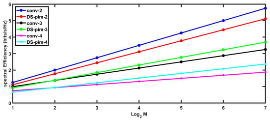
Figure 9.
Spectral fficiency vs. modulation order, for conventional and DS-PIM-based SIM OFDM (index word lengths of 2-bits, 3-bits and 4-bits) where K = 3.
The bandwidth efficiency drops with the increasing sub-block size, as the number of unused subcarriers becomes larger. However, even in case of large sub-blocks, the proposed scheme has a superior bandwidth efficiency due to its variable block size.
Figure 10 shows a theoretical vs. simulated results for spectral efficiency of conventional and DS-PIM-SIM OFDM at k = 2 and n = 4. The results show good agreement between theoretical and simulated values.
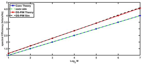
Figure 10.
Theoretical vs. simulated results for spectral efficiency of conventional and DS-PIM-SIM OFDM.
Figure 11 presents a comparison between conventional SIM OFDM and the proposed variant. For a small sub-block size of 4 subcarriers (5 for Proposed approach), the SER performance is quite similar for the two approaches. However, as the sub-block size increases, the conventional approach shows a slight improvement over the proposed approach. This is due to the fact that in DPIM, error is not restricted to one symbol. The effects of error spill over into the next symbol as well (wrong slot error). However, at higher values of CNR, the difference between conventional and proposed approaches again starts to decrease. As discussed in Section 5, this is due to the fact that wrong slot error becomes less likely at higher values of CNR.
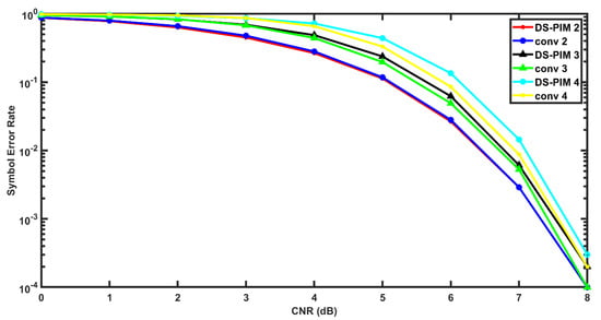
Figure 11.
CNR vs. SER of conventional and DS-PIM based SIM OFDM for index word lengths of 2–bits, 3–bits and 4–bits.
In Figure 8, Figure 9, Figure 10 and Figure 11, the conv-2 and DS-PIM-2 stands for conventional and proposed approach, respectively, for a 2-bit index word. Conv-3 and DS-PIM-3 represent the conventional and proposed variants of SIM OFDM for 3-bit index word, while conv-4 and DS-PIM-4 stands for conventional and proposed approach for a 4-bit index word, respectively.
8. Conclusions
SIM OFDM has been the focus of special interest for visible light communication systems in the recent literature due to its superior bandwidth and power efficiency. However, for higher-order modulation of the modulation bit stream, SIM OFDM tends to lose its advantage, since the subcarriers are carrying a lot more data and the index bits are not enough to compensate for the loss of subcarriers due to index modulation.
The proposed scheme presents a novel approach to SIM-OFDM through variable sub-block size, which enables a dynamic subcarrier assignment. This gives an improved bandwidth efficiency as, for a 2-bit word on the index selection stream, the proposed approach requires 12.5% less bandwidth, since the average number of occupied subcarriers per sub-block are 3.5 instead of 4. Additionally, the bandwidth efficiency is much better than that of conventional SIM OFDM for a higher-order modulation. The compromise in terms of SER is also not very severe, as SER of the proposed approach is also very close to that of conventional SIM OFDM, especially for higher values of CNR.
Author Contributions
Conceptualization, F.U. and A.B.; methodology, F.K.; software, F.K.; validation, F.U. and M.I.; formal analysis, A.B.; investigation, F.K.; resources, M.I.; writing—original draft preparation, F.K.; writing—review and editing, M.I.; visualization, A.B.; supervision, F.U.; project administration, F.U.; funding acquisition, M.I. All authors have read and agreed to the published version of the manuscript.
Funding
This research received no external funding.
Institutional Review Board Statement
Not applicable.
Informed Consent Statement
Not applicable.
Data Availability Statement
Not applicable.
Conflicts of Interest
The authors declare no conflict of interest.
Abbreviations
| List of Abbreviations | |
| Subcarrier Index Modulation OFDM | SIM-OFDM |
| Visible Light Communication | VLC |
| Light Fidelity | LiFi |
| Intensity Modulation/Direct Detection | IM/DD |
| Pulse Amplitude-Modulated Digital Multi-Tone | PAM-DMT |
| Asymmetrically clipped Optical OFDM | ACO-OFDM |
| DC-Biased Optical OFDM | DCO-OFDM |
| Unipolar OFDM | U-OFDM |
| Asymmetrically clipped DC-biased optical OFDM | ADO-OFDM |
| Layered ACO-OFDM | LACO-OFDM |
| OFDM with Index Modulation | OFDM-IM |
| Multiple-Input Multiple-Output | MIMO |
| Dual-Mode index modulation-aided OFDM | DM-OFDM |
| time-domain sample index modulation | TIM |
| indexed dimming | iDim |
| Spectral Efficiency | S.E |
| Carrier-to-Noise Ratio | CNR |
| Signal-to-Noise Ration | SNR |
| Spread Spectrum-aided SIM-OFDM | SS-SIM-OFDM |
| Index Modulation | IM |
| Bit Error Rate | BER |
| Symbol Error Rate | SER |
| Quadrature Amplitude Modulation | QAM |
| Digital Pulse Interval Modulation | DPIM |
| Double-sided Pulse Interval Modulation | DS-PIM |
References
- Alfattani, S. Review of LiFi Technology and Its Future Applications. J. Opt. Commun. 2018, 42, 121–132. [Google Scholar] [CrossRef]
- Badeel, R.; Subramaniam, S.K.; Hanapi, Z.M.; Muhammed, A. A Review on LiFi Network Research: Open Issues, Applications and Future Directions. Appl. Sci. 2021, 11, 11118. [Google Scholar] [CrossRef]
- Tsonev, D.; Chun, H.; Rajabhandari, S.; Mckendry, J.; Videv, S.; Gu, E.; Haji, M.; Watson, S.; Kelly, A.E.; Faulkner, G. A 3Gb/s single-LED based wireless VLC link using gallium nitride µLED. IEEE Photonics Technol. Lett. 2014, 26, 637–640. [Google Scholar] [CrossRef]
- Armstrong, J. OFDM for Optical Communications. J. Lightwave Technol. 2009, 26, 189–204. [Google Scholar] [CrossRef]
- Carruthers, J.; Kahn, J. Multiple subcarrier modulation for non-directed wireless infrared communication. IEEE J. Sel. Areas Commun. 1996, 14, 538–546. [Google Scholar] [CrossRef]
- Armstrong, J.; Lowery, A. A Power efficient OFDM. Electron. Lett. 2006, 42, 370–371. [Google Scholar] [CrossRef]
- Lee, S.; Randel, S.; Breyer, F.; Koonen, A. PAM-DMT for Intensity-modulated and Direct Detection optical communications. IEEE Photonics Technol. Lett. 2009, 21, 1749–1751. [Google Scholar] [CrossRef]
- Tsonev, D.; Sinanovic, S.; Haas, H. Novel Unipolar Orthogonal Frequency Division Multiplexing for optical wireless. In Proceedings of the IEEE Vehicular Technology Conference, Yohohama, Japan, 6–9 May 2012; pp. 1–5. [Google Scholar]
- Fernando, N.; Hong, Y.; Viterbo, E. Flip OFDM for unipolar Communication Systems. IEEE Trans. Commun. 2012, 60, 3726–3733. [Google Scholar] [CrossRef]
- Dissanayake, S.; Armstrong, J. Comparison of ACO-OFDM, DCO-OFDM and ADO-OFDM in IM/DD systems. J. Lightwave Technol. 2013, 31, 1063–1172. [Google Scholar] [CrossRef]
- Wang, Q.; Qian, C.; Gou, X.; Wang, Z.; Cunningham, D.G.; White, I.H. Layered ACO-OFDM for Intensity-modulated Direct-detection optical wireless transmission. Opt. Express 2015, 23, 12382–12393. [Google Scholar] [CrossRef]
- Ranjha, B.; Kavehrad, M. Hybrid asymmetrically clipped OFDM-based IM/DD optical wireless system. J. Opt. Commun. Netw. 2016, 6, 387–396. [Google Scholar] [CrossRef]
- Tsonev, D.; Haas, H. Avoiding Spectral Efficiency loss in unipolar OFDM for optical wireless communication. In Proceedings of the IEEE International Conference on Communications, Sydney, Australia, 10–14 June 2014; pp. 3336–3341. [Google Scholar]
- Wen, M.; Cheng, X.; Yang, L. Index Modulation for 5G Wireless Communications; Springer: Berlin/Heidelberg, Germany, 2017. [Google Scholar]
- Basar, E. Index Modulation techniques for 5 G wireless networks. IEEE Commun. Mag. 2016, 54, 168–175. [Google Scholar] [CrossRef]
- Yang, R.; Ma, S.; Xu, Z.; Li, H.; Liu, X.; Ling, X.; Deng, X.; Zhang, X.; Li, S. Spectral and energy efficiency of DCO-OFDM in Visible Light Communication Systems with finite alphabet inputs. IEEE Trans. Wirel. Commun. 2022, 21, 6018–6032. [Google Scholar] [CrossRef]
- Abu-Alhiga, R.; Haas, H. Subcarrier Index Modulation OFDM. In Proceedings of the 20th IEEE International Symposium on Personal, Indoor and Mobile Radio Communications, Tokyo, Japan, 13–16 September 2009; pp. 177–181. [Google Scholar]
- Tsonev, D.; Sinanovic, S.; Haas, H. Enhanced Subcarrier Index Modulation (SIM) OFDM. In Proceedings of the IEEE GLOBECOM Workshops, Houston, TX, USA, 9 December 2011; pp. 728–732. [Google Scholar]
- Basar, E.; Aygolu, U.; Panayirci, E.; Poor, H. Orthogonal Frequency division multiplexing with index modulation. IEEE Trans. Signal Processing 2013, 61, 5536–5549. [Google Scholar] [CrossRef]
- Ishikawa, N.; Sugiura, S.; Hanzo, L. Subcarrier-index modulation aided OFDM-Will it work? IEEE Access 2016, 4, 2580–2593. [Google Scholar] [CrossRef]
- Basar, E. Multiple-Input Multiple-Output OFDM with index Modulation. IEEE Signal Processing Lett. 2015, 19, 1893–1896. [Google Scholar] [CrossRef]
- Basar, E. On multiple-input multiple-output OFDM with index modulation for next generation wireless networks. IEEE Trans. Signal Processing 2016, 64, 3868–3878. [Google Scholar] [CrossRef]
- Mao, T.; Wang, Z.; Wang, Q.; Chen, S.; Hanzo, L. Dual mode Index modulation aided OFDM. IEEE Access 2017, 5, 50–60. [Google Scholar] [CrossRef]
- Mao, T.; Wang, Q.; Wang, Z. Generalized dual-mode index modulation aided OFDM. IEEE Commun. Lett. 2017, 21, 761–764. [Google Scholar] [CrossRef]
- Chen, C.; Deng, X.; Yang, Y.; Du, P.; Yang, H.; Zhong, W.D. Experimental Demonstration of Optical OFDM with Subcarrier Index Modulation for IM/DD VLC. In Proceedings of the Asia Communications and Photonics Conference, Chengdu, China, 2–5 November 2019. [Google Scholar]
- Eren, T.; Akan, A. Null Subcarrier Index Modulation in OFDM Systems for 6G and beyond. Sensors 2021, 21, 7263. [Google Scholar] [CrossRef]
- Nguyen, T.; Islim, M.; Chen, C.; Haas, H. iDim: Practical implementation of index modulation for LiFi Dimming. IEEE Trans. Green Commun. Netw. 2021, 5, 1880–1891. [Google Scholar] [CrossRef]
- Athisaya, T.; Laxmikandan, T.; Manimekalai, T. Group-indexed orthogonal frequency division multiplexing index modulation aided performance trade off. ETRI J. 2022, 44, 105–116. [Google Scholar] [CrossRef]
- Ngo, V.; Luong, T.; Nguyen, C.L.; Trang, M.X. Enhancing Diversity of OFDM with Joint Spread Spectrum and Subcarrier Index Modulations. Wirel. Netw. 2002, 28, 3739–3751. [Google Scholar] [CrossRef]
- Dogan, S.; Tusha, A.; Basar, E. Multidimensional Index Modulation for 5G and Beyond Wireless Networks. IEEE 2021, 109, 170–199. [Google Scholar] [CrossRef]
- Zheng, D.; Zhang, H.; Song, J. OFDM with Differential Index Modulation for Visible Light Communication. IEEE Photonics J. 2020, 12, 1–8. [Google Scholar] [CrossRef]
- Ghassemlooy, Z.; Hayes, A.R.; Seed, N.L.; Kaluarachchi, E.D. Digital Pulse Interval Modulation for Optical Wireless Communication. IEEE Commun. Mag. 1998, 36, 95–99. [Google Scholar] [CrossRef]
- Kaluarachchi, E.D. Digital Pulse Interval Modulation for Optical Communication Systems. Ph.D. Thesis, Sheffield Hallam University, Sheffield, UK, 1997. [Google Scholar]
- Fuqin, X. Digital Modulation Techniques (Artech House Telecommunications Library); Artech House, Inc.: London, UK, 2006; ISBN 0-89006-970-0. [Google Scholar]
Publisher’s Note: MDPI stays neutral with regard to jurisdictional claims in published maps and institutional affiliations. |
© 2022 by the authors. Licensee MDPI, Basel, Switzerland. This article is an open access article distributed under the terms and conditions of the Creative Commons Attribution (CC BY) license (https://creativecommons.org/licenses/by/4.0/).