Article

A Gysel Power Divider/Combiner with Enhanced Power-Handling Capability

1
Department of Engineering Physics, Tsinghua University, Beijing 100084, China
2
Science and Technology on High Power Microwave Laboratory, Northwest Institute of Nuclear Technology, Xi’an 710024, China
*
Author to whom correspondence should be addressed.
Electronics 2022, 11(17), 2660; https://doi.org/10.3390/electronics11172660
Submission received: 31 July 2022 / Revised: 21 August 2022 / Accepted: 24 August 2022 / Published: 25 August 2022

Abstract

:
By increasing the impedance of the microstrip of the combine port, a new Gysel power combiner/divider (PCD) with enhanced average power-handling capability (APHC) was proposed. This article shows the simulated results of the traditional Gysel PCD and the proposed Gysel PCD at the center frequency of 2.4 GHz and 10 GHz. For verification, one example of the proposed Gysel PCD operating at 2.4 GHz was designed, fabricated, and measured. One traditional Gysel PCD operating at 2.4 GHz was also fabricated to compare the APHC of the proposed Gysel PCD and the traditional Gysel PCD, by means of measuring the temperature variation of the microstrip line at the same power. The measurement result suggests the APHC of the proposed Gysel PCD is nearly twice that of the traditional Gysel PCD.

1. Introduction

The power combiner/divider is an essential passive component in modern radar and microwave communication systems. The Gysel PCD is a popular structure for its simplicity in structure, low insertion loss, and good isolation [1,2]. The current research mainly focuses on improving the isolation or bandwidth of the Gysel PCD [3,4,5], and there is less research on the improvement of the power-handling capability of the Gysel PCD. The maximum average power-handling capability of the microstrip Gysel PCD can be determined by the heating in the materials of microstrip lines (related to the ohmic and dielectric losses). The APHC of microstrip lines was first studied by Gupta, K.C. [6,7]. Later on, different works dealt with APHC for microstrip coupled lines [8,9], coupled-line filters [10,11], filters [12,13], multilayer microstrip lines [14], and thin-film microstrip lines [15,16,17], and there is no research on the APHC of the Gysel PCD from the point of view of the power-handling capacity of the microstrip line. As far as the authors know, the current research on improving the APHC of the Gysel PCD is mainly by increasing the power capacity of the isolation resistors or the number of the isolation resistors [18,19,20], and no research that dealt with the power-handling capacity of the microstrip has been reported.
This article reports a microstrip Gysel PCD with a high impedance of the combine port and high APHC. The simulated results prove that the proposed Gysel PCD has good power distribution and isolation functions for 2.4 GHz and 10 GHz. Thermal characterization measurement results of the traditional and the proposed Gysel PCD at 2.4 GHz implemented on the microstrip are provided validating the proposed method.

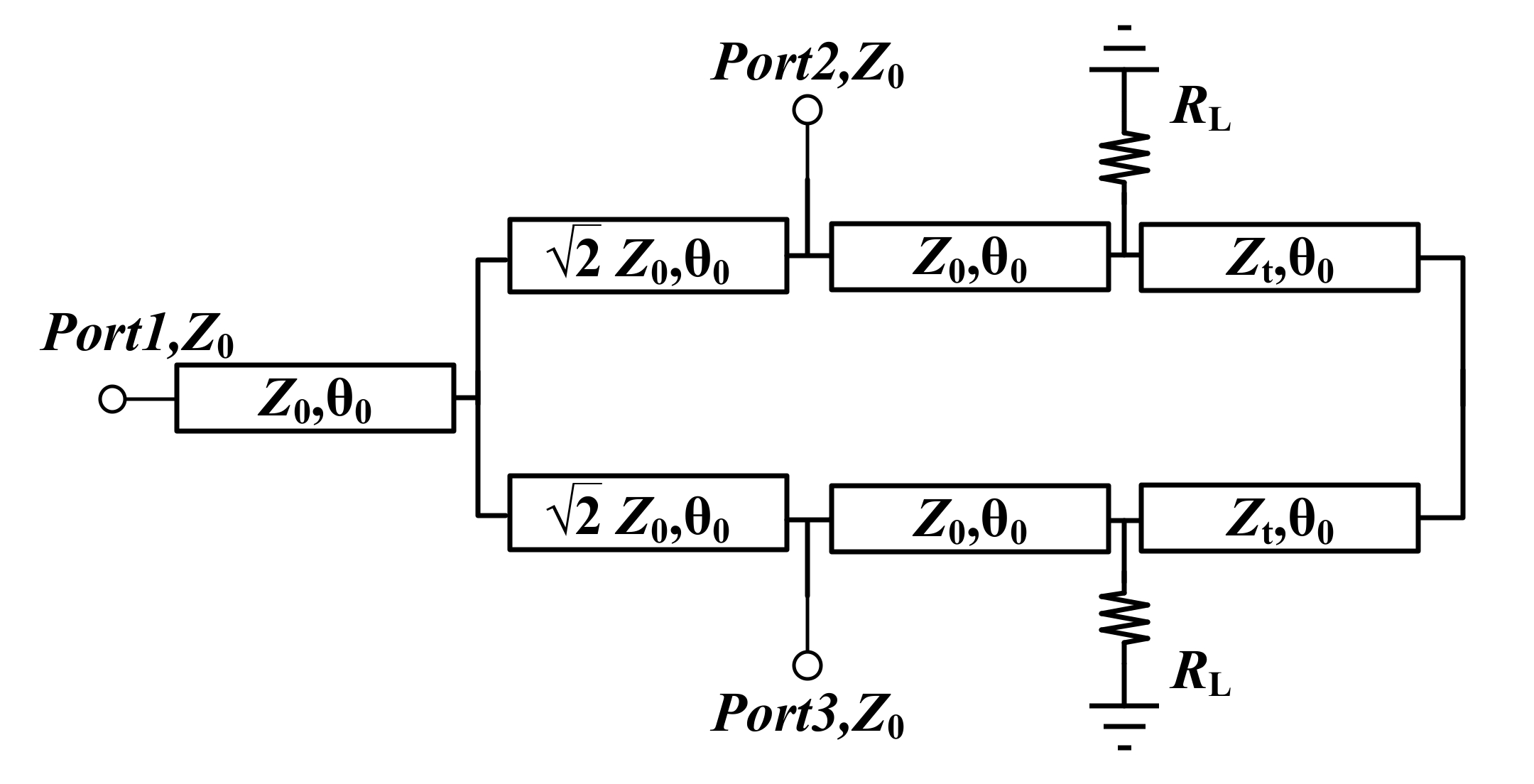
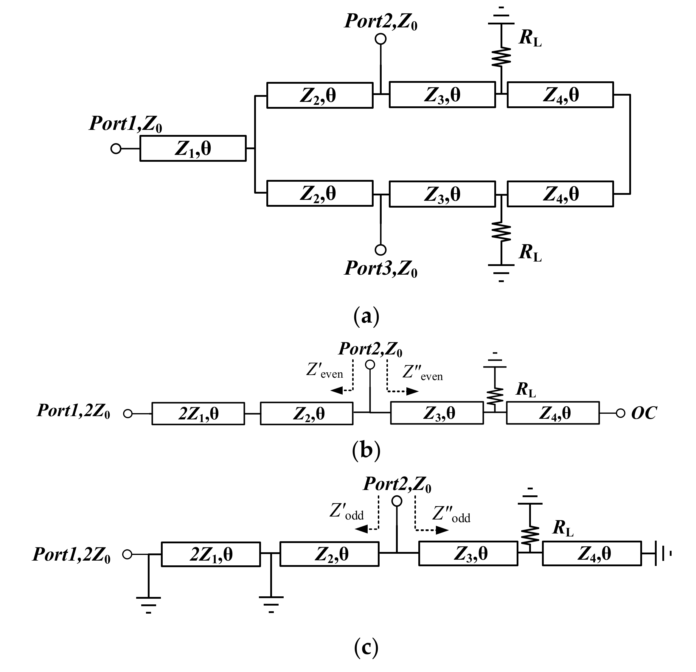
2. Design Theory and Circuit Structure

The generated heat in the microstrip produces a gradient of temperature per unit of power ΔT0 (°C/W) between the strip and the ground plane limiting the maximum APHC. The ΔT0 can be calculated as [5]
Δ T 0 = Δ T c + Δ T d = 2 h ( α c + α d ) K × W e  
where ΔTc and ΔTd are the temperature gradients generated in the microstrip due to conductor and dielectric losses, K is the thermal conductivity of the substrate, αc and αd are the conductor and dielectric attenuation constants (in Np/m), and αc and αd are relevant to the thickness t of the strip and the thickness h of the substrate. We is the thermal effective microstrip width based on a parallel plate waveguide model and can be calculated as [7]
Δ W e = 120 π h Z × ε r
Z and εr are the impedance and effective dielectric constant of the microstrip. Combing (1) and (2), (3) can be derived as
Δ T 0 = Δ T c + Δ T d = ( α c + α d ) × ε r × Z 60 π K
Once ΔT0 is known, the APHC is obtained as
P max = T max T a m b Δ T 0 = 60 π ( T max T a m b ) K Z × ( α c + α d ) × ε r
Tmax is the maximum temperature which can be defined as the temperature at which the circuit changes its electrical or mechanical performance. Tamb is set as a given constant temperature which is generally the ambient temperature. K, αc, αd, and εr are constants when the conductor and dielectric are the same, while h and t are fixed. Therefore, the ΔT0 is proportional to Z, and Pmax is inversely proportional to Z.
Figure 1 shows the traditional microstrip Gysel PCD connected with Z0 = 50 Ω character impedance and two load resistors RL = 50 Ω connecting to the ground plane. The traditional microstrip Gysel PCD is made up of seven lines, and the electrical length θ0 of these lines is 90° at the center frequency.
For the traditional microstrip Gysel PCD, the impedance of the microstrip of divide ports and the combine port is equal, and therefore, the power of the combine port will reach its APHC while the power of divide ports will only reach half of the APHC. The APHC of the combine port will limit the APHC of the traditional microstrip Gysel PCD, and therefore, the APHC of the microstrip Gysel PCD can be improved by increasing the impedance of the microstrip of the combine port.
Figure 2a shows the proposed microstrip Gysel PCD connected with two load resistors RL. As previously analyzed, the APHC of the microstrip is inversely proportional to Z, and the power passing through the combine port is always twice that of divide ports; therefore, it would be reasonable to set Z1 to Z0/2. If Z1 is greater than Z0/2, the APHC of the combine port will limit the APHC of the proposed Gysel PCD; if Z1 is lower than Z0/2, the APHC of divide ports will limit the APHC of the proposed Gysel PCD. The typical even–odd mode method was used to obtain the explicit closed-form equations, which determine the parameters (Z2, Z3, Z4, and RL, and the symbol of admittance is Y = 1/Z, G = 1/R).
Figure 2b shows the equivalent circuit of the proposed Gysel PCD under the even-mode excitation. The center vertical plane is equivalent to a virtual magnetic wall. The impedance of port 1 is doubled. The admittances relation can be formulated and expressed by (5)–(7):
Y e v e n = Y e v e n ' + Y e v e n "
Y e v e n ' = Y 2 Y 1 2 Y 0 + j Y 1 tan θ Y 1 + j Y 0 tan θ + j Y 2 tan θ Y 2 + j Y 1 2 Y 0 + j Y 1 tan θ Y 1 + j Y 0 tan θ tan θ
Y e v e n " = Y 3 G L + j Y 4 tan θ + j Y 3 tan θ Y 3 + j ( G L + j Y 4 tan θ ) tan θ
At the center frequency (θ = 90°), to achieve good impedance matching, Yeven is equal to Y0. According to (5)–(7), we can obtain
Y e v e n = 2 Y 2 2 Y 0 Y 1 2 = Y 0
Z 2 = 2 × Z 1 = 25 2 Ω
Figure 2c shows the equivalent circuit of the proposed Gysel PCD under the odd-mode excitation. In this case, port 1 can simply form a short circuit since the center vertical plane is equivalent to a virtual electric wall. The odd-mode admittance at port 2 can be expressed by (10)–(12):
Y o d d = Y o d d ' + Y o d d "
Y o d d ' = j Y 2 cot θ
Y o d d " = Y 3 G L j Y 4 tan θ + j Y 3 tan θ Y 3 + j ( G L j Y 4 tan θ ) tan θ
To achieve a perfect match and isolation between port 1 and port 2 at the center frequency, Yodd is equal to Y0. Then, we obtain the results as
Y o d d = Y 3 2 2 G L = Y 0
Z 3 = 50 Ω
Note that Z3 does not influence the impedance matching at the center frequency. For a wider frequency band, we choose a lower value of Z3 = 35 Ω.
As discussed above, divide ports and the combine port of the proposed Gysel PCD will be matched at the center frequency.

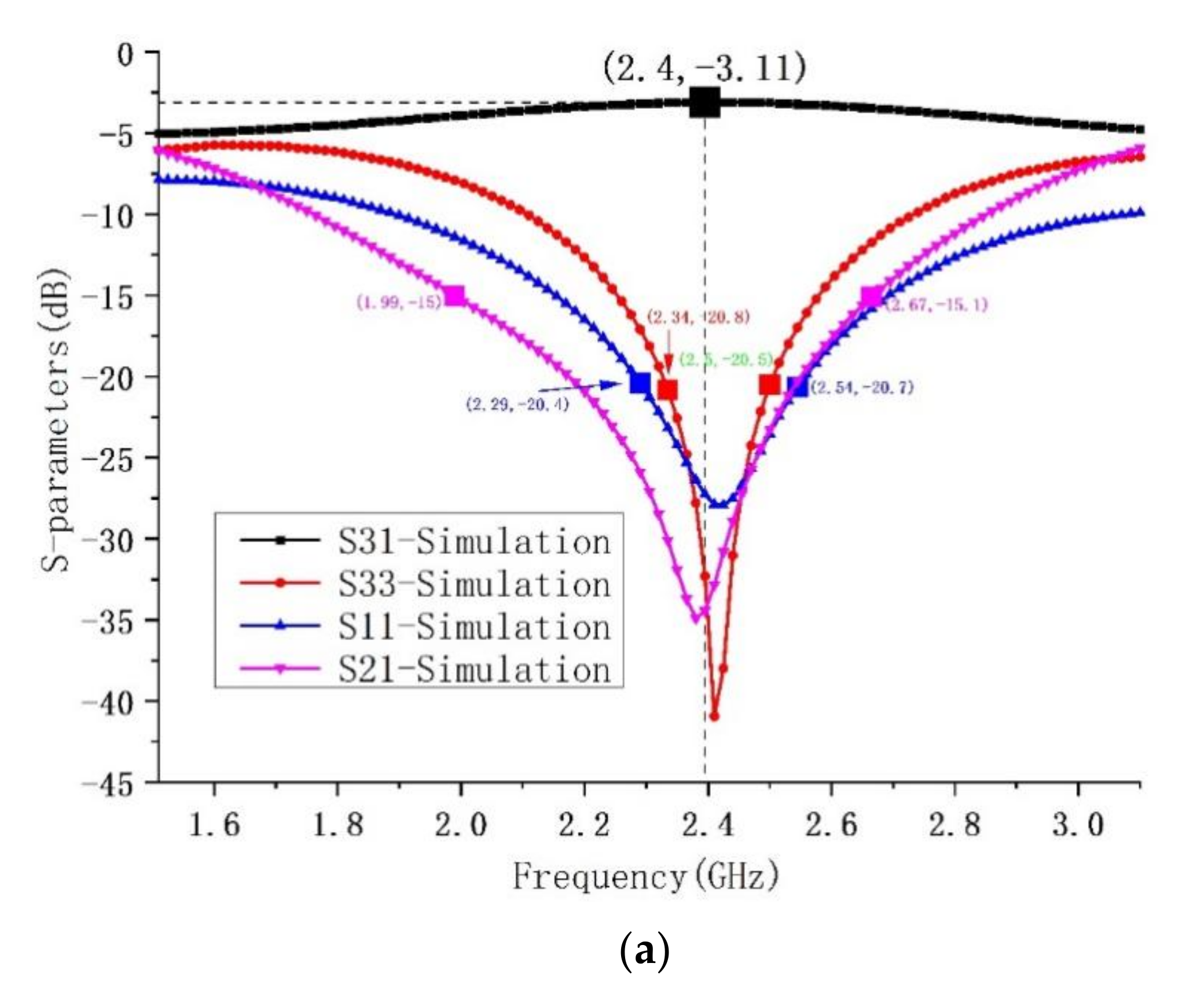
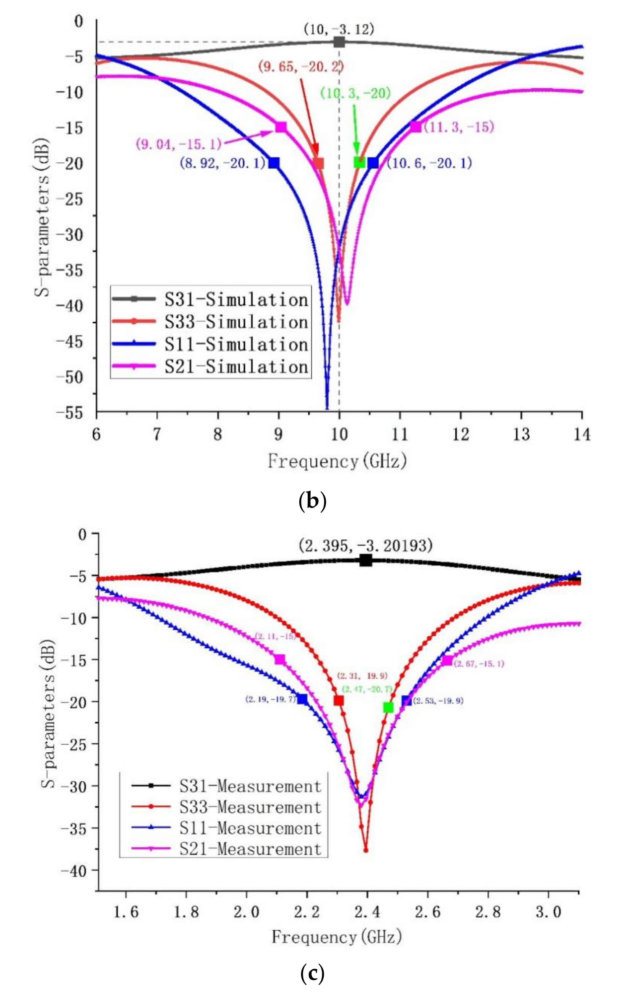
3. Implementation and Measurement

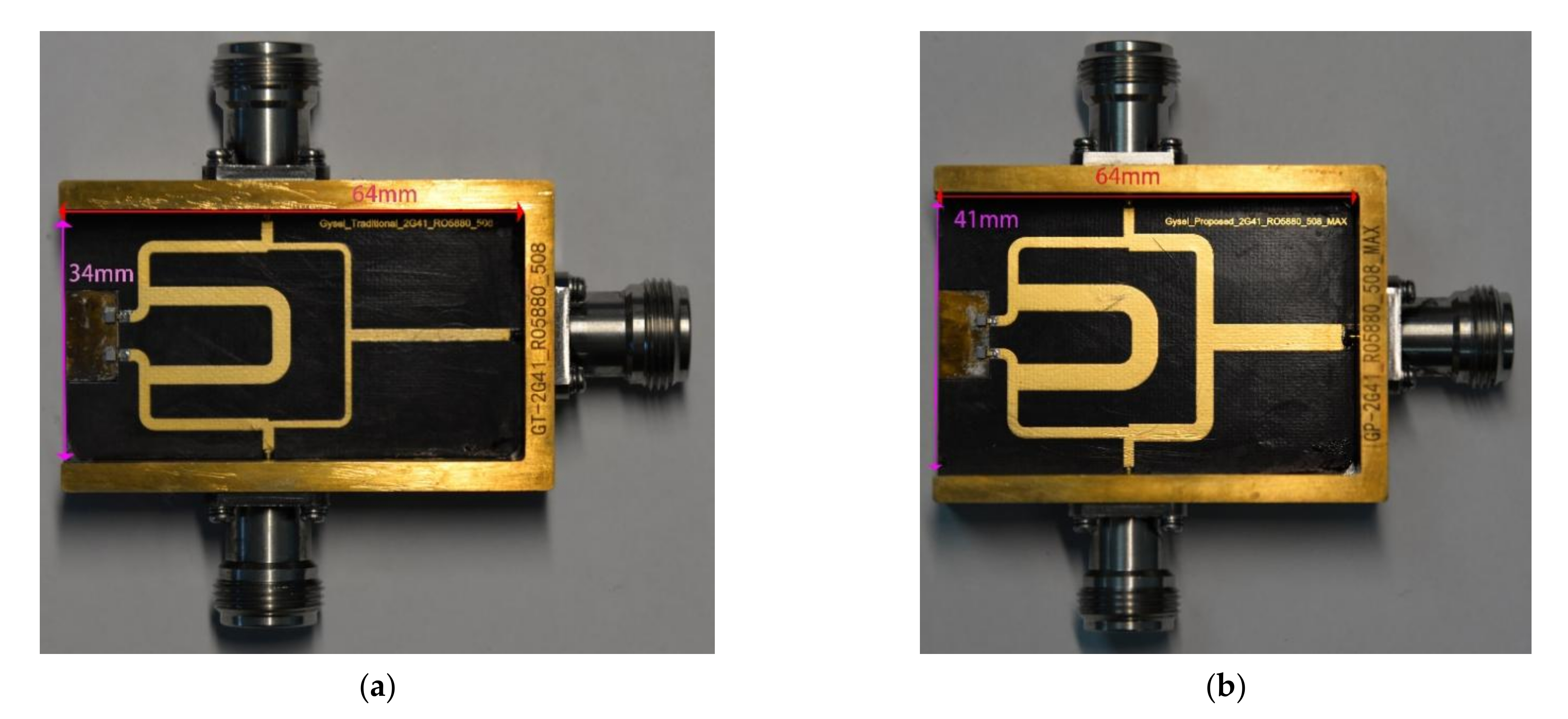
3.1. Prototypes for Traditional Gysel PCD and Proposed Gysel PCD

To verify the proposed design theory, this study used the Advanced Design System to simulate the performance of the traditional Gysel PCD and the proposed Gysel PCD at the center frequency of 2.4 GHz and 10 GHz. To validate the proposed method, a traditional Gysel PCD and a proposed Gysel PCD at 2.4 GHz were fabricated. The circuits were designed and implemented on a Rogers5880 substrate with a relative dielectric constant of 2.2 and a thickness of 0.508 mm, and the thickness of the metal layer was 17.5 μm. The manufacturer of the substrate is Rogers Corporation from Chandler, Arizona, USA. Chip resistors and bent microstrip lines were used to decrease the size of the fabricated circuits. The parameter values of the proposed PCD were Z1 = 25 Ω, Z2 = 35.35 Ω, Z3 = 50 Ω, Z4 = 35 Ω, and RL = 50 Ω. Figure 3a,b shows the layouts of the fabricated traditional Gysel PCD and fabricated proposed Gysel PCD, respectively. The fabricated traditional Gysel PCD had a length of 64 mm and a width of 34 mm, and the fabricated proposed Gysel PCD had a length of 64 mm and a width of 41 mm. The measurement was carried out on a network analyzer.
Figure 4a,b show the simulated S-parameters of the proposed Gysel PCD at the center frequency of 2.4 GHz and 10 GHz, respectively. S21 represents the isolation between divide ports, S31 represents the insertion loss between one divide port and the combine port, S33 represents the return loss of the combine port, and S11 represents the return loss of one divide port. The measured isolation is better than 15 dB from 2.31 to 2.65 GHz, and the measured return loss is better than 20 dB from 2.31 GHz to 2.47 GHz. The measured insertion loss S31 is 3.21 dB. The simulation results show that the proposed Gysel PCD has good isolation and insertion loss at the center frequency of both 2.4 GHz and 10 GHz. Figure 4c shows the measured S-parameters of the fabricated proposed Gysel PCD. The measured isolation S21 is better than 15 dB from 2.11 to 2.67 GHz, and the measured return loss S33 is better than 20 dB from 2.31 GHz to 2.47 GHz. The measured insertion loss S21 at the center frequency is less than 3.21 dB.
Figure 5 shows the measured S-parameters of the traditional Gysel PCD and the proposed Gysel PCD. S31 represents the insertion loss between one divide port and the combine port, and S33 represents the return loss of the combine port. The insertion loss S31 of the traditional Gysel PCD and the proposed Gysel PCD is nearly the same at the center frequency.

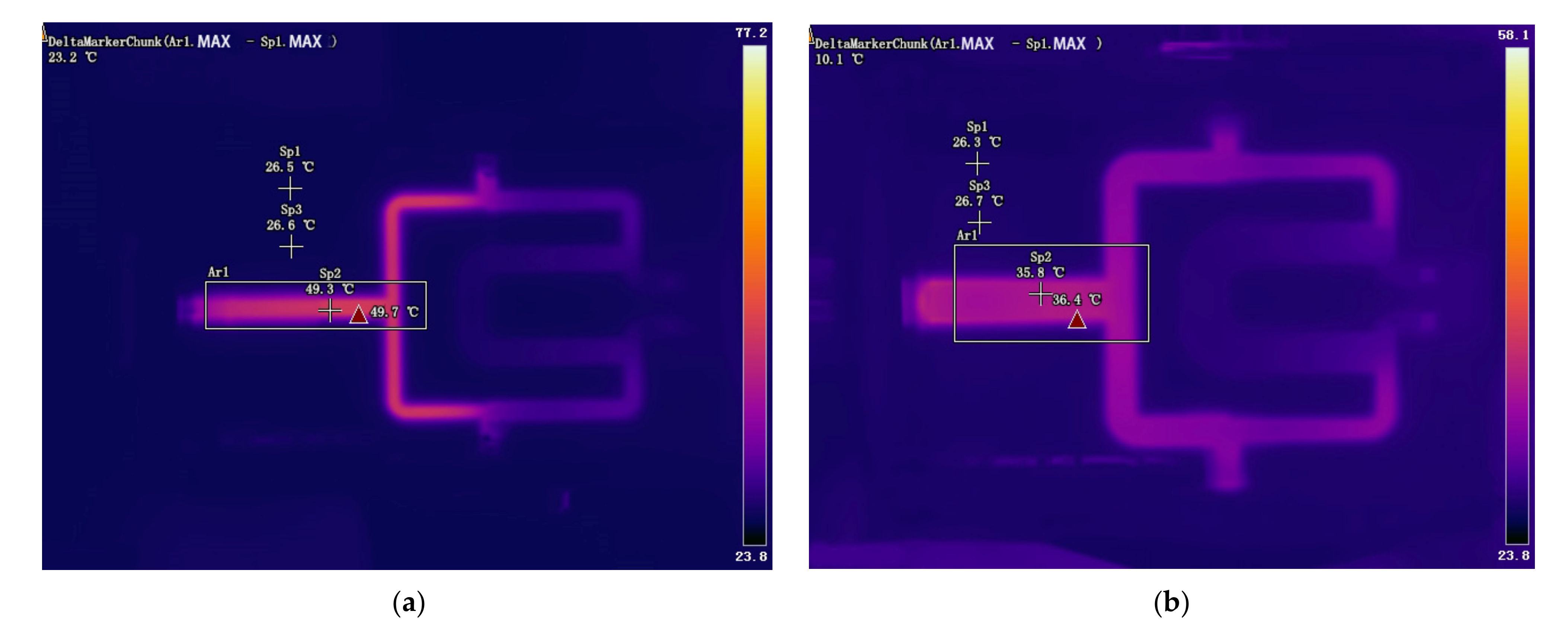
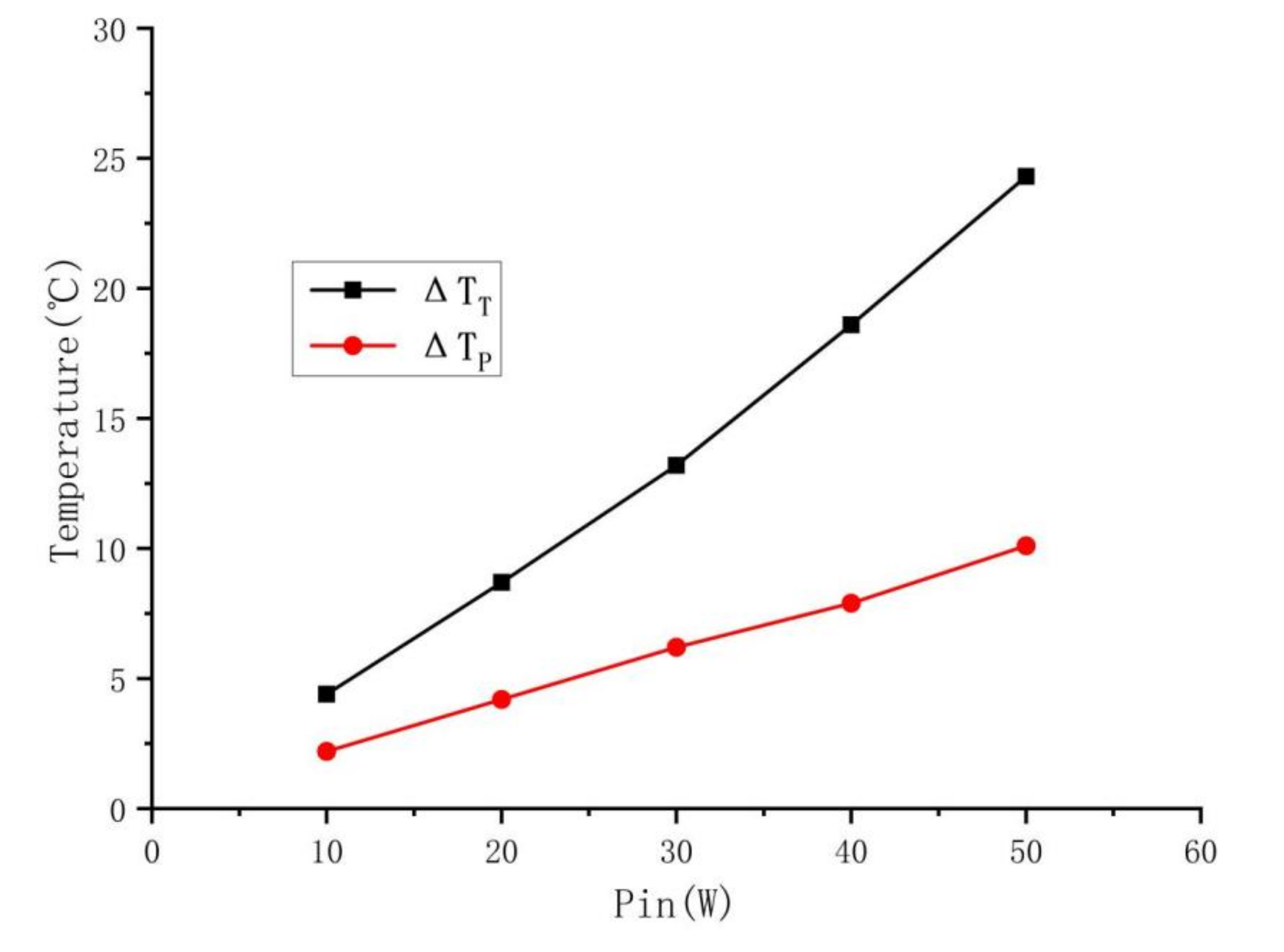
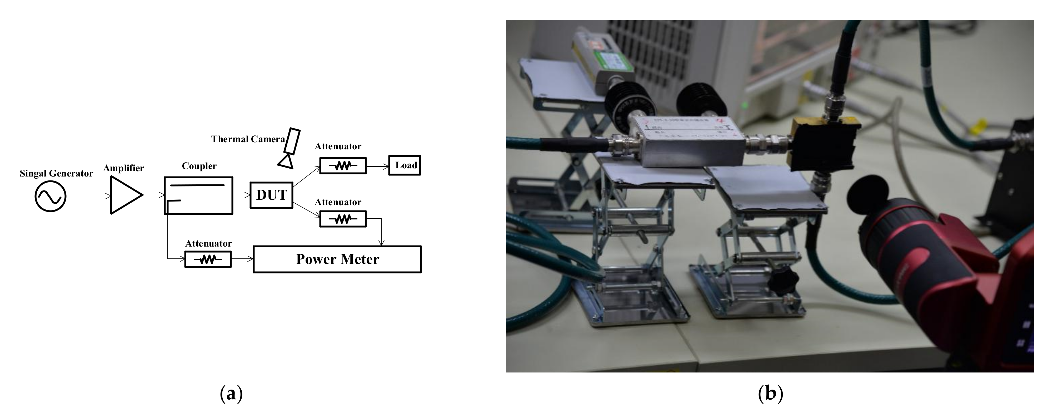
3.2. Thermal Characterization Measurement Experimental Results and Analysis

To verify the proposed design, a thermal characterization measurement setup was arranged to measure the thermal profile of the device with an infrared camera for the traditional Gysel PCD and the proposed Gysel PCD. Figure 6a shows the measurement setup for thermal characterization of the device under test (DUT). Figure 6b shows the photograph of one of the DUTs. The DUT is suspended above the table so that all its layers are subject to natural convection. Since the infrared camera measures thermal radiation rather than direct temperature, it is necessary to cover the DUT surface with black tape to obtain accurate results. The function of the black tape is to increase the emissivity of the DUT and minimize the influence of the environment.
In this measurement setup, a continuous signal was applied to the circuit at 2.4 GHz (center frequency). The input power was set to 10 W, 20 W, 30 W, 40 W, and 50 W, respectively. At the moment when the signal generator was switched on, the thermal profile of the DUT was recorded. The ambient temperature was maintained at 26 °C during the experiment.
Figure 7 shows the thermal profiles of the traditional Gysel PCD and the proposed Gysel PCD when the input power of 50 W is just switched on. The maximum hot spot can be identified on the microstrip of the combine port as predicted. For the traditional Gysel PCD, the temperature variation (temperature difference between the maximum temperature of the microstrip of the circuit and the ambient temperature) caused by the input power is ΔTT = 23.2 °C. For the proposed Gysel PCD, the temperature variation caused by the input power is ΔTP = 10.1 °C.
Figure 8 shows the temperature variation ΔTT and the temperature variation ΔTP at different input powers. The measurements show that when the input power is the same, ΔTT is at least twice as high as ΔTP. Since the Tmax of the fabricated traditional Gysel PCD and the fabricated proposed Gysel PCD are the same, combined with (4), it can be found that the APHC of the proposed Gysel PCD is at least twice that of the traditional Gysel PCD.

4. Conclusions

A proposed Gysel PCD with high APHC was designed, fabricated, and measured. One traditional PCD was also fabricated to compare the APHC of the proposed PCD and the traditional PCD. The temperature variation of the traditional Gysel PCD is at least twice that of the proposed Gysel PCD at the same input power, which suggests that the APHC of the fabricated proposed Gysel PCD is nearly twice that of the traditional Gysel PCD. This approach can also be applied to a Gysel PCD consisting of multiple layers of microstrip lines.

Author Contributions

Conceptualization, C.F., T.H. and W.F.; methodology, C.F. and W.H.; software, C.F.; validation, C.F., T.H. and W.F.; formal analysis, C.F. and R.F.; investigation, C.F. and T.H.; resources, Y.Z.; data curation, L.W.; writing—original draft preparation, C.F. and W.F.; writing—review and editing, C.F., W.H. and R.F.; visualization, C.F. and Y.C.; supervision, Y.C.; project administration, Y.Z.; funding acquisition, W.H. All authors have read and agreed to the published version of the manuscript.

Funding

This research received no external funding.

Data Availability Statement

Not applicable.

Conflicts of Interest

The authors declare no conflict of interest.

References

  1. Gysel, U.H. A New N-Way Power Divider/Combiner Suitable for High-Power Applications. In Proceedings of the 1975 IEEE-MTT-S International Microwave Symposium, Palo Alto, CA, USA, 12–14 May 1975; pp. 116–118. [Google Scholar]
  2. Zhu, Z.; Wang, Z.; Fu, Y.; Fang, S.; Liu, H.; Chen, Z.N. Unlimited Power Division Ratio of Microstrip Balanced-to-Unbalanced Gysel-Type Arbitrary Power Divider. Electronics 2020, 9, 1124. [Google Scholar] [CrossRef]
  3. Shahi Gharehaghaji, H.; Shamsi, H. Design of Unequal Dual Band Gysel Power Divider With Isolation Bandwidth Improvement. IEEE Microw. Wirel. Compon. Lett. 2017, 27, 138–140. [Google Scholar] [CrossRef]
  4. He, J.; Luo, W.; Chen, S. A Gysel Power Divider with Enhanced Isolation Bandwidth. In Proceedings of the 2015 Asia-Pacific Microwave Conference (APMC), Nanjing, China, 6–9 December 2015; Volume 3, pp. 1–3. [Google Scholar]
  5. Lin, F.; Chu, Q.-X.; Gong, Z.; Lin, Z. Compact Broadband Gysel Power Divider with Arbitrary Power-Dividing Ratio Using Microstrip/Slotline Phase Inverter. IEEE Trans. Microw. Theory Tech. 2012, 60, 1226–1234. [Google Scholar] [CrossRef]
  6. Gupta, K.C.; Garg, R.; Bahl, I.; Bhartia, P. Microstrip Lines and Slotlines; Artech House: London, UK, 2013; p. 7. [Google Scholar]
  7. Bahl, I.J.; Gupta, K.C. Average Power-Handling Capability of Microstrip Lines. IEE J. Microw. Opt. Acoust. 1979, 3, 1. [Google Scholar] [CrossRef]
  8. Yin, W.Y.; Dong, X.T. Wideband Average Power Handling Capability of Coupled Microstrips on Polyimide and PolyimideGaAs Substrates. IEE Proc. Microw. Antennas Propag. 2004, 151, 385. [Google Scholar] [CrossRef]
  9. Yin, W.-Y.; Dong, X.; Gan, Y.B. Frequency-Dependent Maximum Average Power-Handling Capabilities of Single and Edge-Coupled Microstrip Lines on Low-Temperature Co-Fired Ceramic (LTCC) Substrates. Int. J. RF Microw. Comput. Aided Eng. 2006, 16, 103–117. [Google Scholar] [CrossRef]
  10. Wu, L.-S.; Zhou, X.-L.; Yin, W.-Y.; Tang, M.; Zhou, L. Characterization of Average Power Handling Capability of Bandpass Filters Using Planar Half-Wavelength Microstrip Resonators. IEEE Microw. Wirel. Compon. Lett. 2009, 19, 686–688. [Google Scholar] [CrossRef]
  11. Wu, L.-S.; Mao, J.; Yin, M.Y.; Tang, M. Average Power Handling Capability of Quarter-Wavelength Microstrip Stepped-Impedance Resonator Bandpass Filter. In Proceedings of the 2012 IEEE/MTT-S International Microwave Symposium Digest, IEEE, Montreal, QC, Canada, 17–22 June 2012; pp. 1–3. [Google Scholar]
  12. Yu, M. Power-Handling Capability for RF Filters. IEEE Microw. 2007, 8, 88–97. [Google Scholar] [CrossRef]
  13. Sanchez-Soriano, M.A.; Quere, Y.; Le Saux, V.; Quendo, C.; Cadiou, S. Average Power Handling Capability of Microstrip Passive Circuits Considering Metal Housing and Environment Conditions. IEEE Trans. Compon. Packag. Manuf. Technol. 2014, 4, 1624–1633. [Google Scholar] [CrossRef]
  14. Bahl, I.J. Average Power Handling Capability of Multilayer Microstrip Lines. Int. J. RF Microw. Comput. Aided Eng. 2001, 11, 385–395. [Google Scholar] [CrossRef]
  15. Yin, W.-Y.; Dong, X.T. Wide-Band Characterization of Average Power Handling Capabilities of Some Microstrip Interconnects on Polyimide and Polyimide/GaAs Substrates. IEEE Trans. Adv. Packag. 2005, 28, 328–336. [Google Scholar] [CrossRef]
  16. Yin, W.-Y.; Dong, X.T.; Mao, J.; Li, L.W. Average Power Handling Capability of Finite-Ground Thin-Film Microstrip Lines over Ultra-Wide Frequency Ranges. IEEE Microw. Wirel. Compon. Lett. 2005, 15, 715–717. [Google Scholar] [CrossRef]
  17. Yin, W.-Y.; Kang, K.; Mao, J.-F. Electromagnetic-Thermal Characterization of on On-Chip Coupled (A)Symmetrical Interconnects. IEEE Trans. Adv. Packag. 2007, 30, 851–863. [Google Scholar] [CrossRef]
  18. Fahmi, M.M.; Ruiz-Cruz, J.A.; Mansour, R.R. Compact Ridge Waveguide Gysel Combiners for High-Power Applications. IEEE Trans. Microw. Theory Tech. 2019, 67, 968–977. [Google Scholar] [CrossRef]
  19. Guan, J.; Zhang, L.; Sun, Z.; Leng, Y.; Peng, Y. Designing Power Divider by Combining Wilkinson and Gysel Structure. Electron. Lett. 2012, 48, 769. [Google Scholar] [CrossRef]
  20. Oraizi, H.; Sharifi, A.-R. Optimum Design of a Wideband Two-Way Gysel Power Divider With Source to Load Impedance Matching. IEEE Trans. Microw. Theory Tech. 2009, 57, 2238–2248. [Google Scholar] [CrossRef]
Figure 1. Traditional microstrip Gysel PCD.
Electronics 11 02660 g001
Figure 2. The proposed microstrip Gysel PCD and the even/odd mode circuit of the proposed microstrip Gysel PCD. (a) The proposed microstrip Gysel PCD. (b) The even-mode circuit. (c) The odd-mode circuit.
Electronics 11 02660 g002
Figure 3. The fabricated traditional Gysel PCD and the fabricated proposed Gysel PCD. (a) The fabricated traditional Gysel PCD. (b) The fabricated proposed Gysel PCD.
Electronics 11 02660 g003
Figure 4. (a) The simulated S-parameters of the fabricated proposed Gysel PCD at the center frequency of 2.4 GHz. (b) The simulated S-parameters of the fabricated proposed Gysel PCD at the center frequency of 10 GHz. (c) The measured S-parameters of the fabricated proposed Gysel PCD at the center frequency of 2.4 GHz.
Electronics 11 02660 g004aElectronics 11 02660 g004b
Figure 5. Measured S-parameters of the traditional Gysel PCD and the proposed Gysel PCD.
Electronics 11 02660 g005
Figure 6. Measurement setup for the thermal characterization of the device under test and photograph of one of the measuring devices. (a) Measurement setup for the thermal characterization of the device under test. (b) Photograph of one of the measuring devices.
Electronics 11 02660 g006
Figure 7. The thermal profiles of the traditional Gysel PCD and the proposed Gysel PCD when the input power of 50 W is just switched on. (a) The thermal profiles of the traditional Gysel PCD. (b) The thermal profiles of the proposed Gysel PCD.
Electronics 11 02660 g007
Figure 8. The ΔTT and the ΔTP at different input powers.
Electronics 11 02660 g008
Publisher’s Note: MDPI stays neutral with regard to jurisdictional claims in published maps and institutional affiliations.

