Article

Smart, Fast, and Low Memory Beam-Steering Antenna Configurations for 5G and Future Wireless Systems

by
Kandasamy Pirapaharan
1,*,
Nagananthakumaran Ajithkumar
1,
Konesamoorthy Sarujan
1,
Xavier Fernando
2 and
Paul R. P. Hoole
3,4
1
Department of Electrical and Electronic Engineering, University of Jaffna, Jaffna 40000, Sri Lanka
2
Electrical, Computer, and Biomedical Engineering, Toronto Metropolitan University, Toronto, ON M5B 2K3, Canada
3
Wessex Institute of Technology, Southampton SO16 7NS, UK
4
Electrical and Communications Engineering Department, University of Technology, Lae 411, Papua New Guinea
*
Author to whom correspondence should be addressed.
Electronics 2022, 11(17), 2658; https://doi.org/10.3390/electronics11172658
Submission received: 27 July 2022 / Revised: 18 August 2022 / Accepted: 22 August 2022 / Published: 25 August 2022
(This article belongs to the Special Issue Numerical Electromagnetic Problems Involving Antennas)

Abstract

:
Smart Antennas are important to provide mobility support for many enhanced 5G and future wireless applications and services, such as energy harvesting, virtual reality, Voice over 5G (Vo5G), connected vehicles, Machine-to-Machine Communication (M2M), and Internet of Things (IoT). Smart antenna technology enables us to reduce interference and multipath problems and increase the quality in communication signals. This paper presents a number of nonlinear configurations of dipole arrays for forming a single beam in any desired direction. We propose three, four, six, and eight-element array structures to perform this single beam-steering functionality. The proposed array configurations with multiple axes of symmetry (in the azimuthal plane) decrease the computational repetitions in optimizing respective weight factors for beam-steering. The optimized weight factors are obtained through the Least Mean Square (LMS) method. MATLABTM is used to calculate optimized weight factors as well as to determine the resulting radiation patterns. Since antennas are bidirectional elements, beamforming in one direction means that the antenna will also have high receiving gain in that direction. Performances of differently configured models are compared in terms of their directivity, sidelobe reduction, and computational complexities for beam-steering.

1. Introduction

The need for wireless communication rapidly increases in various systems and applications. Higher channel capacity, increased data rates, and spectrum efficiency with reduced interference are the challenges for today’s wireless communication technologies [1]. The demand for wide bandwidth channels has resulted in new approaches for the efficient use of the available spectrum [2]. The vast increment in the number of wireless users and IoT nodes gives rise to a spectrum crunch. Wireless energy harvesting approaches are on the rise to address the energy crunch of low-power IoT nodes. Space Division Multiple Access (SDMA), adaptive beamforming, and smart antennas are key technologies for the current fifth-generation (5G) and future sixth-generation (6G) communication systems [2,3].
A Smart Antenna or Adaptive Antenna is an antenna array aided by a processing system that operates on the transmitted or received signals with signal processing algorithms to enrich the system performances [4]. Smart Antenna Technology enables us to reduce interference and multipath problems while increasing the quality of communication signals [3].
Smart antennas are essential to boost the harvested energy in energy harvesting systems as well. This is done by maximizing reception in the received signal direction [5,6]. Smart Antennas are also crucial to provide mobility support for many new and enhanced 5G applications and services such as Voice over 5G (Vo5G), self-driving automobiles, connected vehicles, virtual reality, IoT, and Machine-to-Machine Communication (M2M) [7]. Note, since antennas are bidirectional elements, beamforming in one direction also means that the antenna will have high receiving gain in that direction.
Conventional cellular base stations are not aware of a mobile device’s location and they transmit power omnidirectionally [2]. This wastes power, increases interference, and makes it difficult to detect weak incoming signals. On the other hand, the smart antenna technology can spatially track mobile devices by adjusting the radiation pattern to optimize both transmission and reception to/from each user’s device. By rapidly adjusting the signal phase of several antennas, the base station can effectively steer a beam or receive Radio Frequency (RF) energy from any direction [1,2].
Single beamforming and beam-steering will completely avoid the problematic sidelobe radiations. Single beamforming is achieved by combining signal streams from multiple elements of a non-linear antenna array in both constructive and destructive ways [8]. Beams are steered to the required directions and controlled by different configurations of antenna arrays with designated phase delays to the respective elements. While multi-beam antenna arrays with steerable beams are attractive to achieve high channel capacity and multispot coverage [9], here we focus on single beam antennas.
Beam-steering is the technique of sending/receiving information from/to the intended users while minimizing it to interferers in the form of radiation nulls [10,11]. Advanced signal processing methods incorporated with artificial intelligence are used in beam-steering techniques to achieve the optimum power to/from the user while minimizing interference. Hence, the efficiency improves as interference and noise are reduced [12].
Most of the past smart antenna research has been on array systems where the antenna elements are placed along a straight line, as a uniform linear array (ULA). Random placement of dipoles arranged in a ULA would generate a symmetrical radiation pattern on both sides of the line of the axis where the dipoles are placed [13,14,15,16,17]. As a result, it is not possible to form a single beam by placing any number of dipoles in a ULA setup. A ULA setup has the disadvantage of unproductive power transmission due to the multi-path reflections that could occur when a duplicate of the main beam is generated in the opposite direction on the axis of the dipole placement [14,15,16,17,18]. The drawback of such an antenna is more extensive at the receiving end, where reflected waves from both sides of the axis are received, lowering the signal quality and performance. Therefore, we propose a single-beam smart antenna for 5G and 6G applications. Many patch-type antennas are proposed and published; however, we review only the most relevant ones [19,20] in our literature review since, although different antennas are designed with different shapes for operating at different frequency bands, their beamforming mechanism remains the same. In almost every case, multiple directional patch-type radiators are placed in fixed directions. These radiators are sequentially activated with the help of a tuning circuit; thus, only a single radiator is active at a particular instant and the radiation directions are fixed for that particular patch element. Consequently, these antennas cannot be used for directing beams in random directions. As opposed to the fixed direction of beamforming using patch-type antenna array systems, our proposed array model is capable of directing the beam in any desired direction. Note that we are not proposing another patch antenna system here.
In our proposed dipole array scheme, a minimum of three dipoles are required to make a non-linear configuration that can be used to steer a single beam in the azimuth angle range [14]. Furthermore, more elements promise a narrower beam with higher directivity. It is obvious that compared to omnidirectional radiation, a narrow, highly directional beam would provide long-distance coverage using less power.
Even more accurate beamforming with less computation is possible when the dipoles are placed at the vertices of a structure that has multiple symmetrical axes in the azimuthal plane. In this scenario, shifting weights through adjacent vertices would shift the entire field pattern by the same angle. This characteristic will help us to steer the beam in small increments without having to recalculate the weights. According to the existing configurations, the minimum number of dipoles required to steer a single beam in the azimuth angle range is three [14]. More elements will ensure a narrow beam with the desired shape. Compared to an omnidirectional antenna, a narrow beam would provide better coverage for the target user while using less power. In the study [14,21], a three-element Equilateral Triangular Model, a four-element Square Model, and a six-element Regular Hexagonal Model are proposed for the single beamforming antenna array.
In this paper, we propose three, four, six, and eight-element non-linear arrays for the single beamforming antenna array configurations. Regular polygon array antenna models that have a maximum number of symmetrical axes in the azimuthal plane, reduce the computational replication of optimizing the phase delay factors for steering the beam in each direction. On the other hand, these regular polygon models may not provide desired single beam solutions for all angles to be steered. Therefore, we have also studied different array configurations for six and eight-element models with multiple symmetrical axes in the azimuthal plane.
We have used a Least Mean Square (LMS) approach based on closed-form solutions to optimize the phase delay factors. MATLABTM is used as the software tool in software programming of the simulation codes to optimize weights as well as to determine and display the subsequent radiation patterns. Our study shows that using a six-element two-triangular array configuration, we can direct the single beam to different angles by the step of 30° throughout 0° to 360°, similar to the six-element regular hexagonal configuration in [14]. However, both configurations are failing at different sets of angles to have an exact match with the desired radiation pattern. Thus, in these studies, we have proposed a regular octagon configuration and two models of two-square configurations using eight elements. Moreover, we test for steering the single beam through 0° to 360° angles in steps of 15°. As a result, the Smart Antenna design permits us to have coverage of the entire spatial area surrounding the antenna.

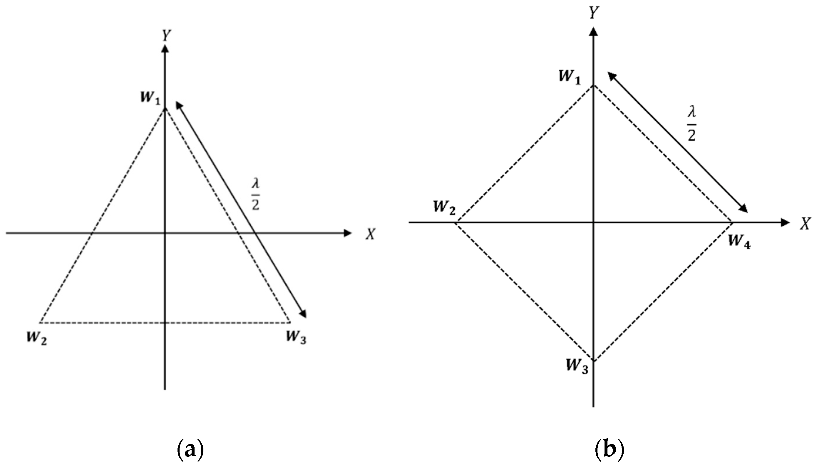
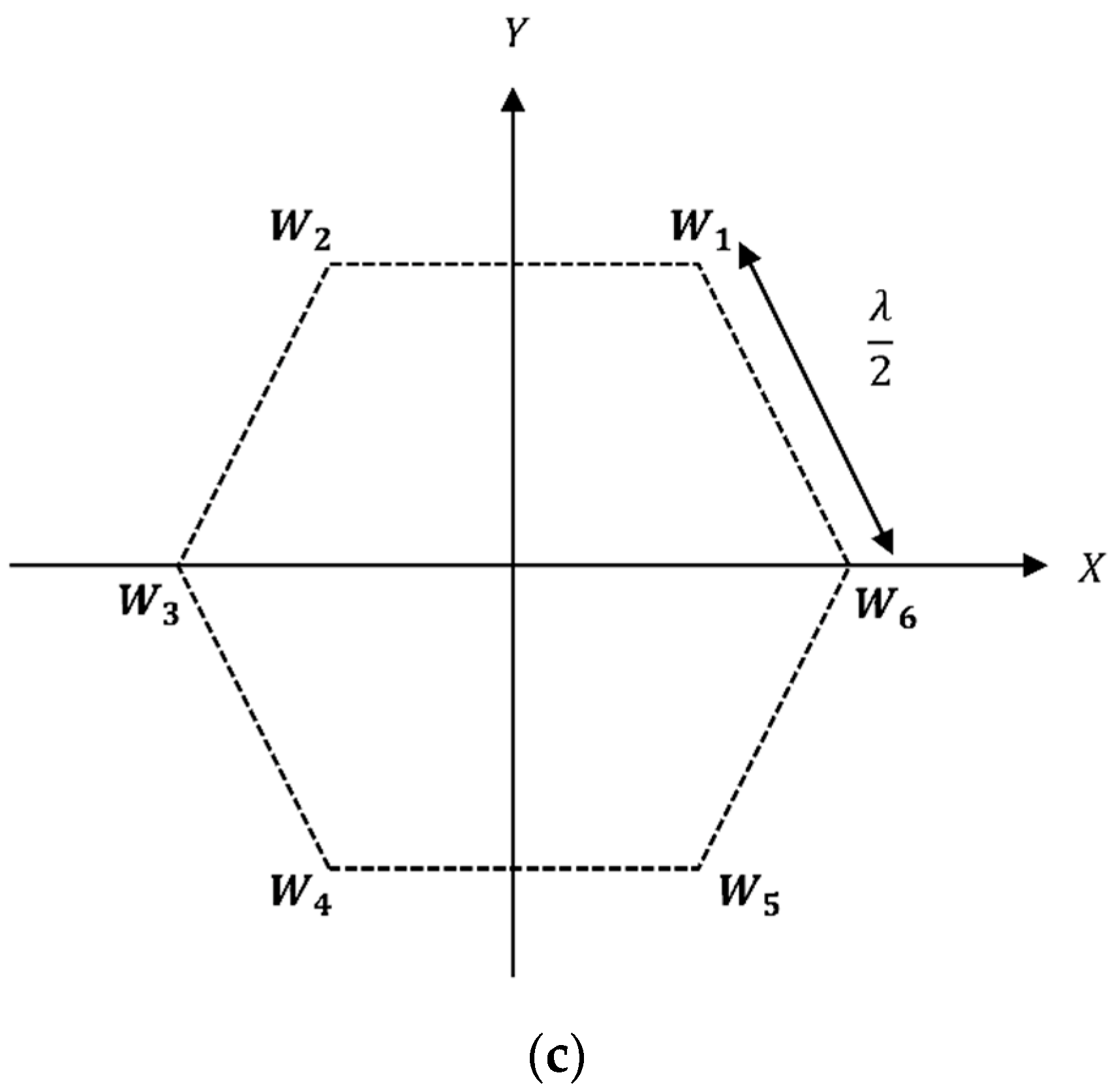
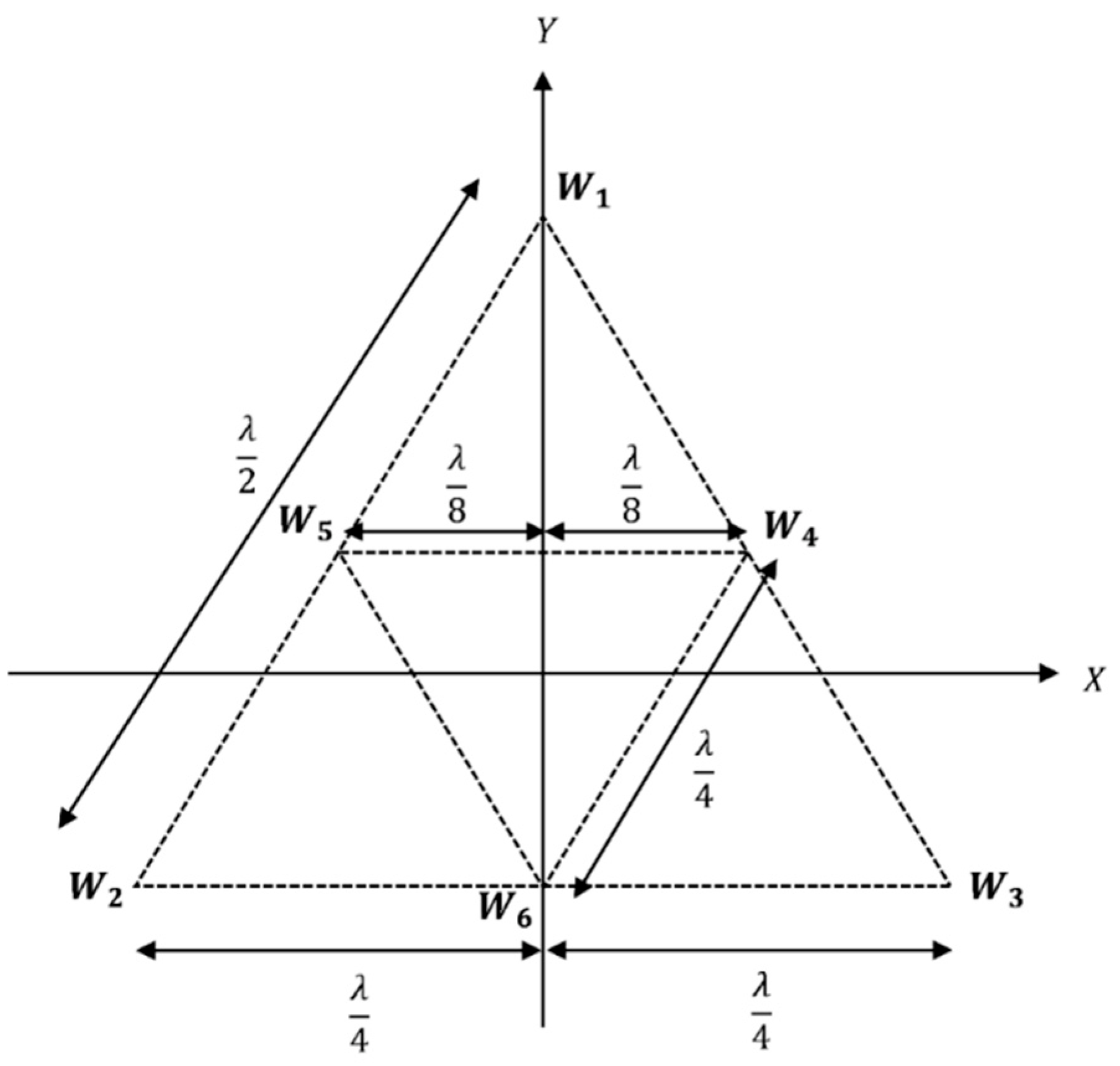
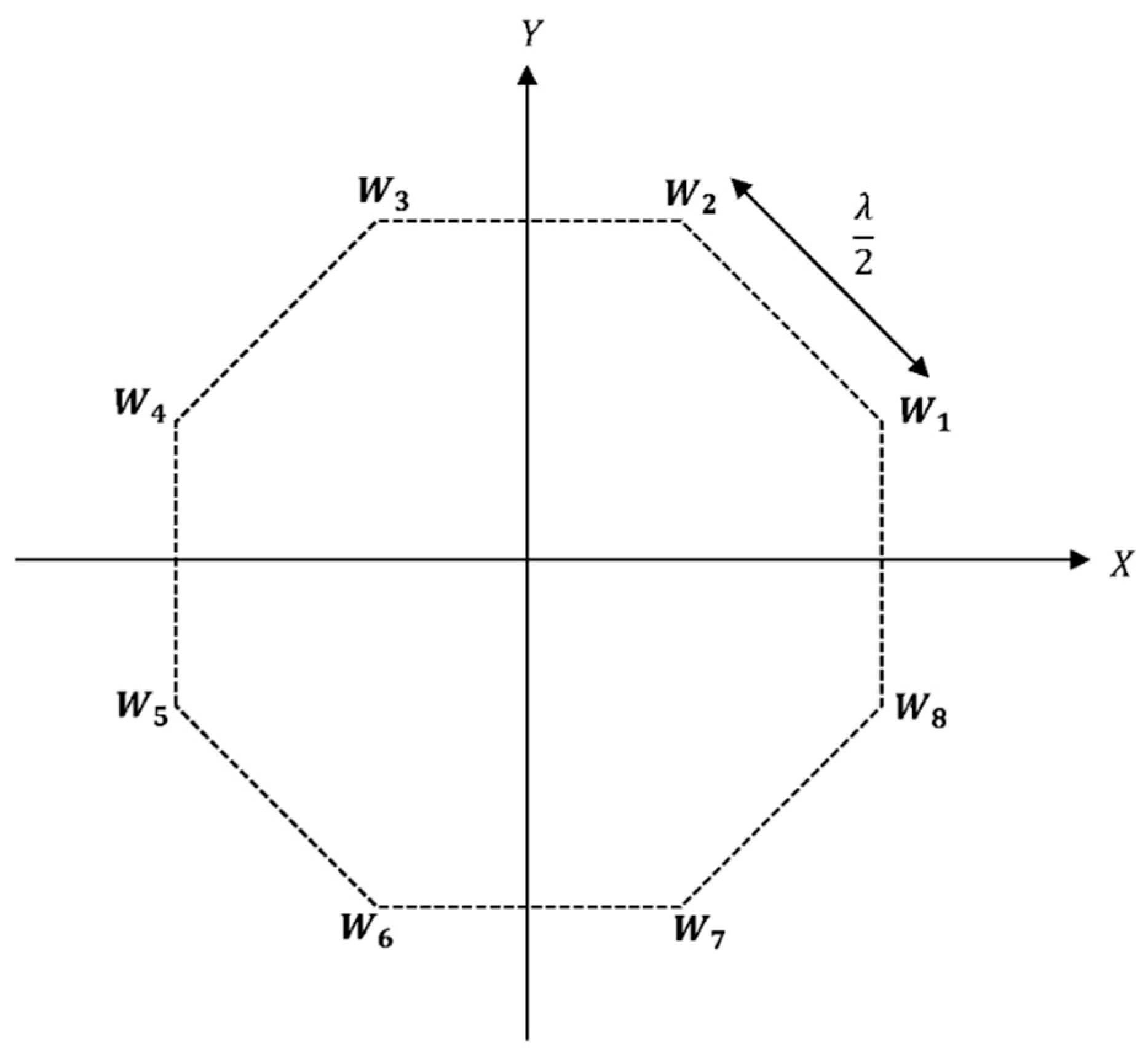
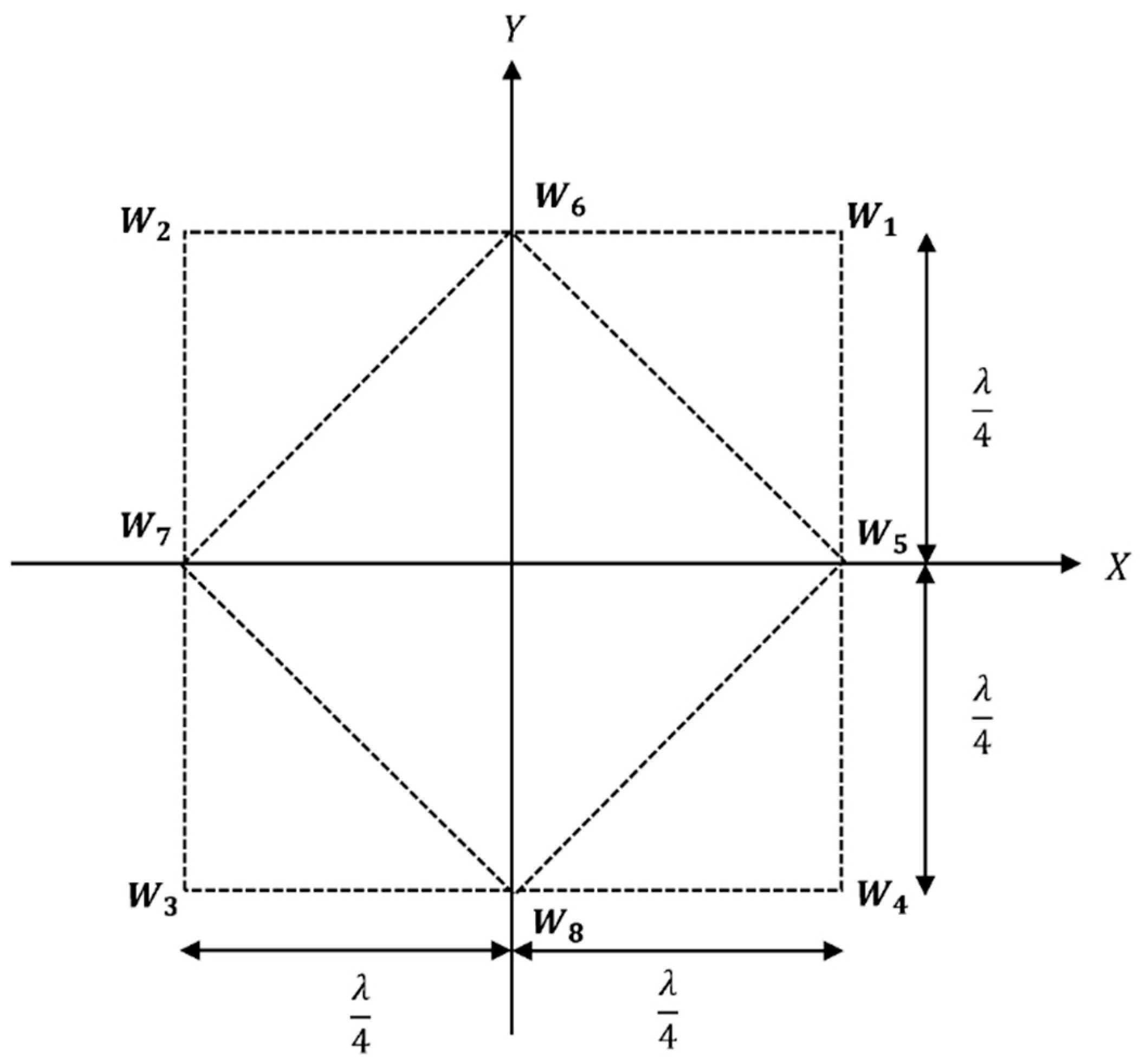
2. Antenna Array Configurations for a Single Rotatable Beam

As mentioned previously in [14], the minimum number of dipoles required to steer a single beam in the azimuth angle range (0° to 360°) is three. In the study [14], a three-element equilateral triangular configuration, a four-element square configuration, and a six-element regular hexagonal configuration were proposed for the single beamforming, non-linear array antenna. These configurations are shown in Figure 1. W1, W2, W3, etc. are the complex phase delay factors of the respective antenna elements in the array model.
When phase delay factors are shifted from end-to-end vertices, the entire radiation pattern is steered by an angle that the end-to-end vertices make at the origin [11]. This characteristic will allow us to steer the beam in increments without recalculating the weights when the dipoles are positioned at the vertices of a structure, which have multiple axes of symmetry in the azimuthal plane.
In this arrangement, we propose configurations of a six-element two-triangular, eight-element regular octagon, and two models of two-square antenna array systems to obtain a single, steerable beam for 5G and future applications. Shown in Figure 2 is the schematic diagram of the proposed two-triangular antenna array. The distance between the antenna elements in the larger triangle is   λ / 2 , and it is λ / 4 for the smaller triangle. W1, W2, and W3 are the complex phase delay factors of the larger triangle; W4, W5, and W6 are the complex phase delay factors of the smaller triangle. Here, to steer the beam in a new direction, we have to simultaneously shift the phase delay factors of both triangles by 120°.
Shown in Figure 3 is the schematic diagram of the proposed regular octagonal configuration. The distance between the antenna elements is   λ / 2 . W1, W2, W3, W4, W5, W6, W7, and W8 are the complex phase delay factors of the vertices in the regular octagonal. Here, to steer the beam in a new direction, we have to move the phase delay factors to adjacent vertices by 45°.
Figure 4 and Figure 5 show the schematic diagrams of the proposed two configurations of two-square antenna arrays. In both configurations, the distance between the antenna elements in the larger square is λ / 2 . The distance between the antenna elements in the smaller square is 2 λ / 4 in configuration 1 and λ / 4   in configuration 2. W1, W2, W3, and W4 are the complex phase delay factors of the larger square and W5, W6, W7, and W8 are the complex phase delay factors of the smaller square. Here, to steer the beam in a different direction, we have to shift the phase delay factors of both squares simultaneously to the respective adjacent vertices by 90°.

Optimization of Phase Delay Factors

The real-time optimization of phase delay factors (weights) is a challenging task. Research is being carried out to optimize the weights by various algorithms using neural networks and artificial intelligence techniques [4,8,11,15]; however, the computational complexities and memory requirements are high for these complex algorithms. In contrast, we have developed an elegant, computationally simpler, closed-form method based on the studies published in [22,23], where minimization of the LMS error is used as a basis of the formulation. The derivation of this closed-form method along with tested solutions for the equilateral triangular, square, and regular hexagonal configurations have been published by us in [14] and will not be repeated here. In addition, in this paper, we propose using the symmetrical properties of the structure to further reduce computational complexities.
When the dipole elements are placed in a regular polygon, as shown in Figure 6, the resulting beam can be advanced by an angle 2 π / N , where N is the number of sides of the polygon. Here, the angle between the two vertices from the center of the polygon, θ is 2 π / N . The mathematics behind this advancement is illustrated in Equations (1)–(6).
The electric field at point P for the dipoles shown in Figure 6 can be written as:
E φ = W 1 e j β a c o s α c o s φ + s i n α s i n φ + W 2 e j β a c o s θ + α c o s φ + s i n θ + α s i n φ + W 3 e j β a c o s 2 θ + α c o s φ + s i n 2 θ + α s i n φ + W N e j β a c o s N 1 θ + α c o s φ + s i n N 1 θ + α s i n φ
Equation (1) can be simplified to:
E φ = W 1 e j β a c o s α φ + W 2 e j β a c o s θ + α φ + W 3 e j β a c o s 2 θ + α φ ) + W N e j β a c o s N 1 θ + α φ
The radiation field at point P could be evaluated from Equation (2) for arbitrary phase delay factors. For the model shown in Figure 7, we name the element with weight W1 as the 1st element, that with weight W2 as the 2nd element, and weight WN as the Nth element, etc. Now we can shift the weights by angle θ so that the 1st element is with weight WN, the 2nd element with weight W1, the 3rd element with W2, and the Nth element with weight WN−1. For the new weight factors, the radiation field can be obtained using Equation (2) and simplified as shown below:
E ¯ φ = W N e j β a c o s α φ + W 1 e j β a c o s θ + α φ + W 2 e j β a c o s 2 θ + α φ ) + W N 1 e j β a c o s N 1 θ + α φ
Using the trigonometric identity,
c o s α φ = c o s 2 π + α φ = c o s N θ + α φ
We can rewrite Equation (3) as:
E ¯ φ = W N e j β a c o s N θ + α φ + W 1 e j β a c o s θ + α φ + W 2 e j β a c o s 2 θ + α φ ) + W N 1 e j β a c o s N 1 θ + α φ
By further rearranging, we can write Equation (5) as:
E ¯ φ = W 1 e j β a c o s θ + α φ + W 2 e j β a c o s θ + θ + α φ ) + W N 1 e j β a c o s θ + N 2 θ + α φ + W N e j β a c o s θ + N 1 θ + α φ = E θ + φ
Since E ¯ φ = E θ + φ   . By shifting the weights to end-to-end vertices, we may say that the entire radiation pattern can be steered by the same angle. This will allow steering the beam in the steps of the same angle without reevaluating the weights.

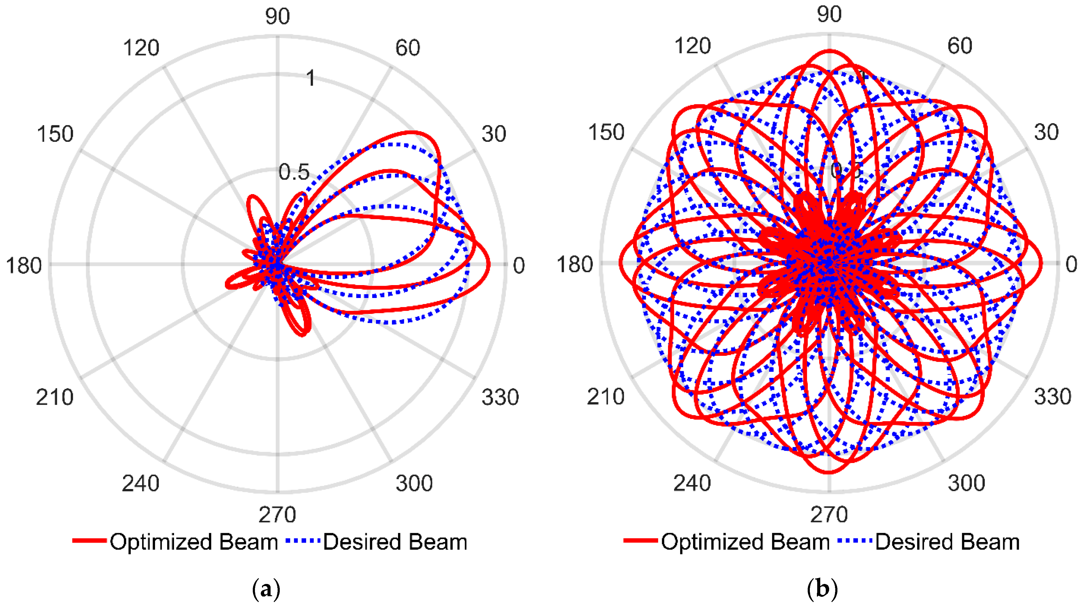
3. Numerical Evaluations

We have developed MATLABTM codes to numerically compute the closed-form solution that optimizes the phase delay factors. MATLABTM is also used to graphically display the radiation patterns. MATLABTM inbuilt functions such as integration, matrix inversion, and matrix multiplication can be easily converted to C language or something similar at the implementation stage. Numerical evaluations of different configurations are compared below.

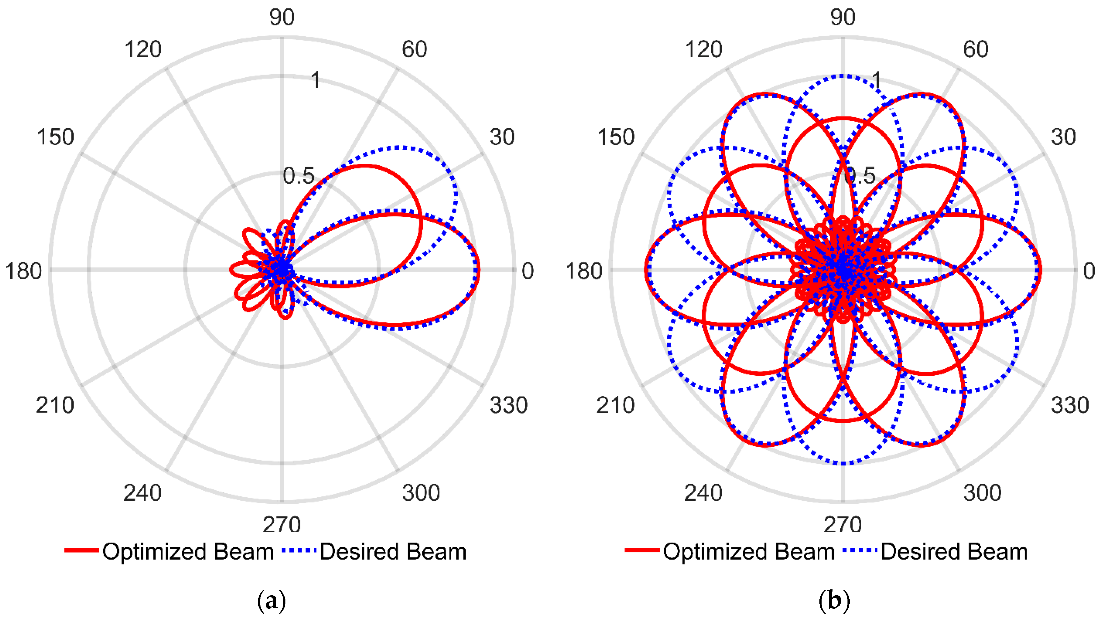
3.1. Beam Shifting at 30° Steps

In this section, the results generated by the realistic simulations of the array designs shown in Figure 3, Figure 4, Figure 5 and Figure 6 are reported, in order to demonstrate the single beam pattern and steered beam pattern achieved by these novel array antenna configurations. In order to obtain the smart antenna phase delay elements, we specify ideal, desired beams in specific directions, to computationally determine the optimized weights. Subsequently, we test the optimized weights to determine the beam shapes in other directions with phase shifting. The optimized phase delay factors are obtained through the LMS method. MATLABTM is used to first optimize the weights in the LMS method, and then to use these optimized weights on the array antennas to obtain the radiation patterns.
Beam patterns generated by six-element array configurations when using LMS optimization are shown in Figure 7 and Figure 8. After calculating the weight values for 0° and 30°, we can again steer the beam to 60°, 90°, 120°, 150°, 180°, 210°, 240°, 270°, 300°, and 330° for the regular hexagonal configuration as shown in Figure 7b. When considering the regular hexagonal configuration, we have a perfect beam match at 0° but not at 30°. Therefore, when the desired angle is at 30°, 90°, 150°, 210°, 270°, and 330°, we get a beam pattern with a larger beam-width than the desired single beam width.
In the Two-Triangular Configuration, after calculating the weight values for 0°, 30°, 60°, and 90°, we can again steer the beam to 120°, 150°, 180°, 210°, 240°, 270°, 300°, and 330° as shown in Figure 8b. In the two-triangular configuration, we obtained an almost perfect beam match to the desired single beam pattern when the desired angle is 30° or 90° but not at 0° or 60°. Consequently, at 0°, 60°,120°, 180°, 240°, and 300°, we get a beam pattern with a larger beam width than the desired single beam pattern. Therefore, we observe that we can steer the beam through 30°, 90°, 150°, 210°, 270°, and 330° with an almost perfect match to the desired beam.
Note that, in the 6-element structure, with reference to one of the dipole positions, five different space vectors exist toward the rest of the dipole positions. Every space vector contributes as different space harmonics (phase shifts) components to direct the beam to the desired direction. The number of space harmonics (five in number) may not be enough to perfectly direct the beam throughout the angles of 0° to 360°. On the other hand, depending on the configuration where the same number of dipoles are placed in a different order, we were able to get a perfect match at a different set of angles. Hence, we can say that by increasing the number of elements and identifying the appropriate dipole positioning configurations, we can have the perfect match for more desired angles. This is tested in the next section.

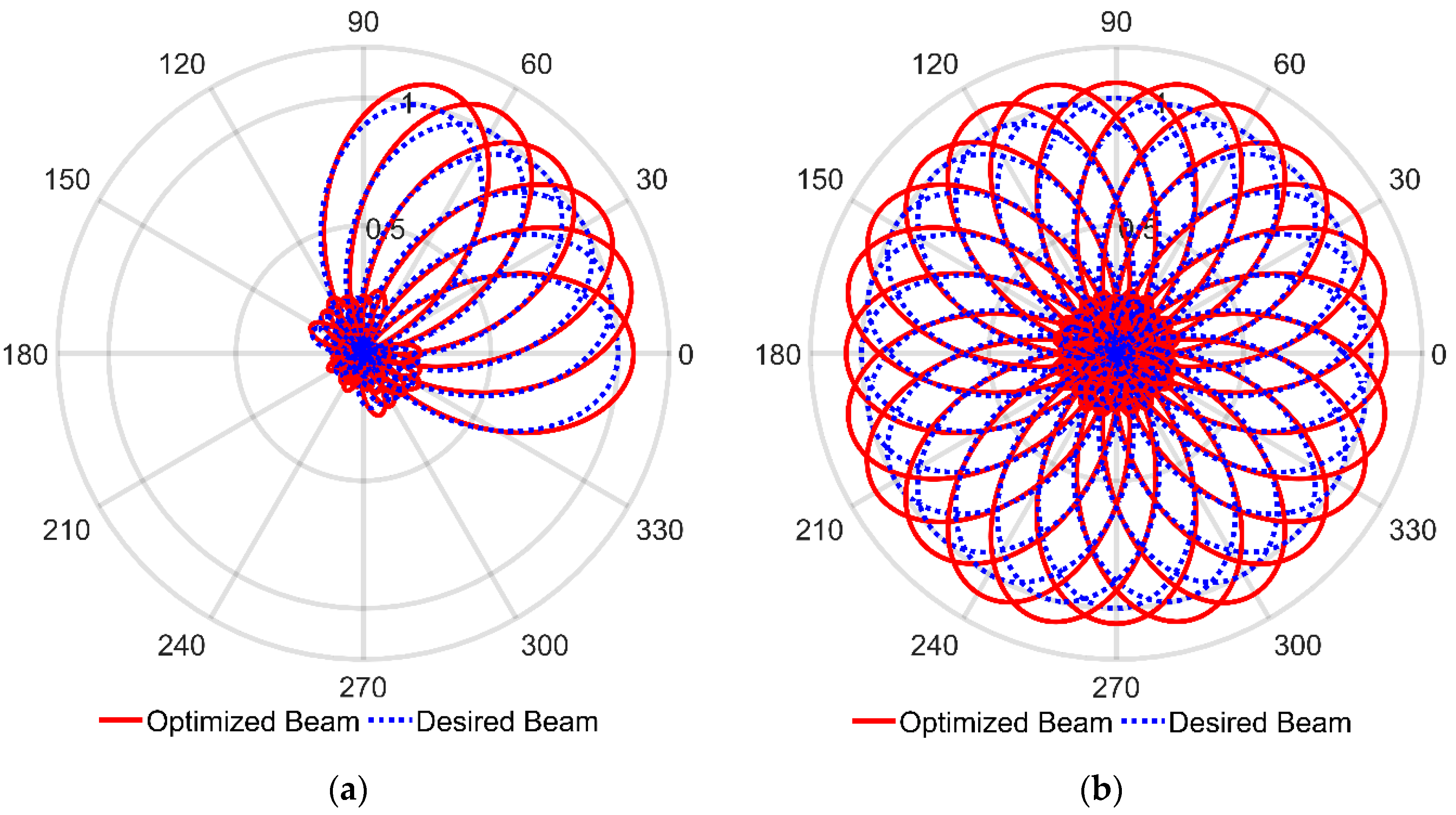
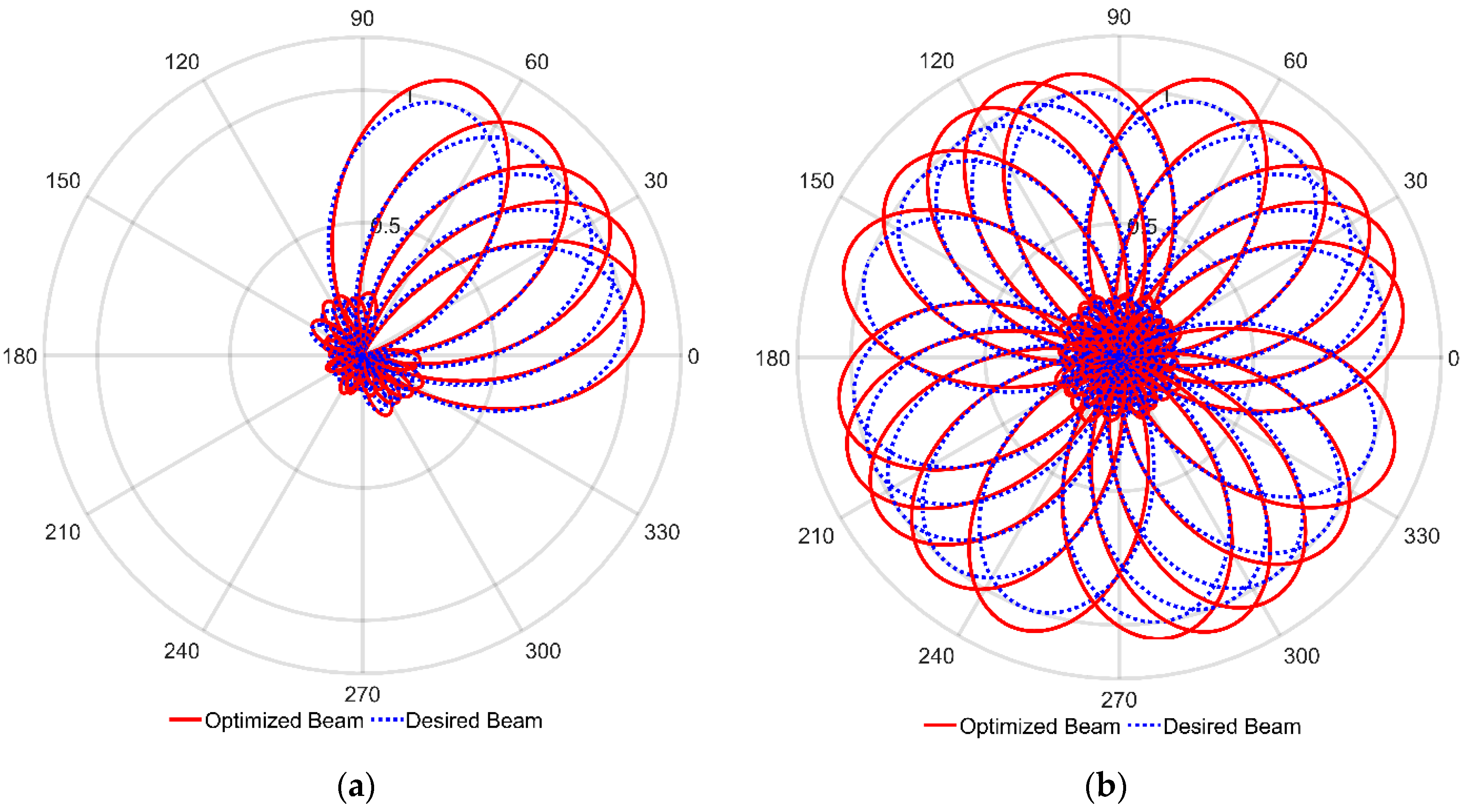
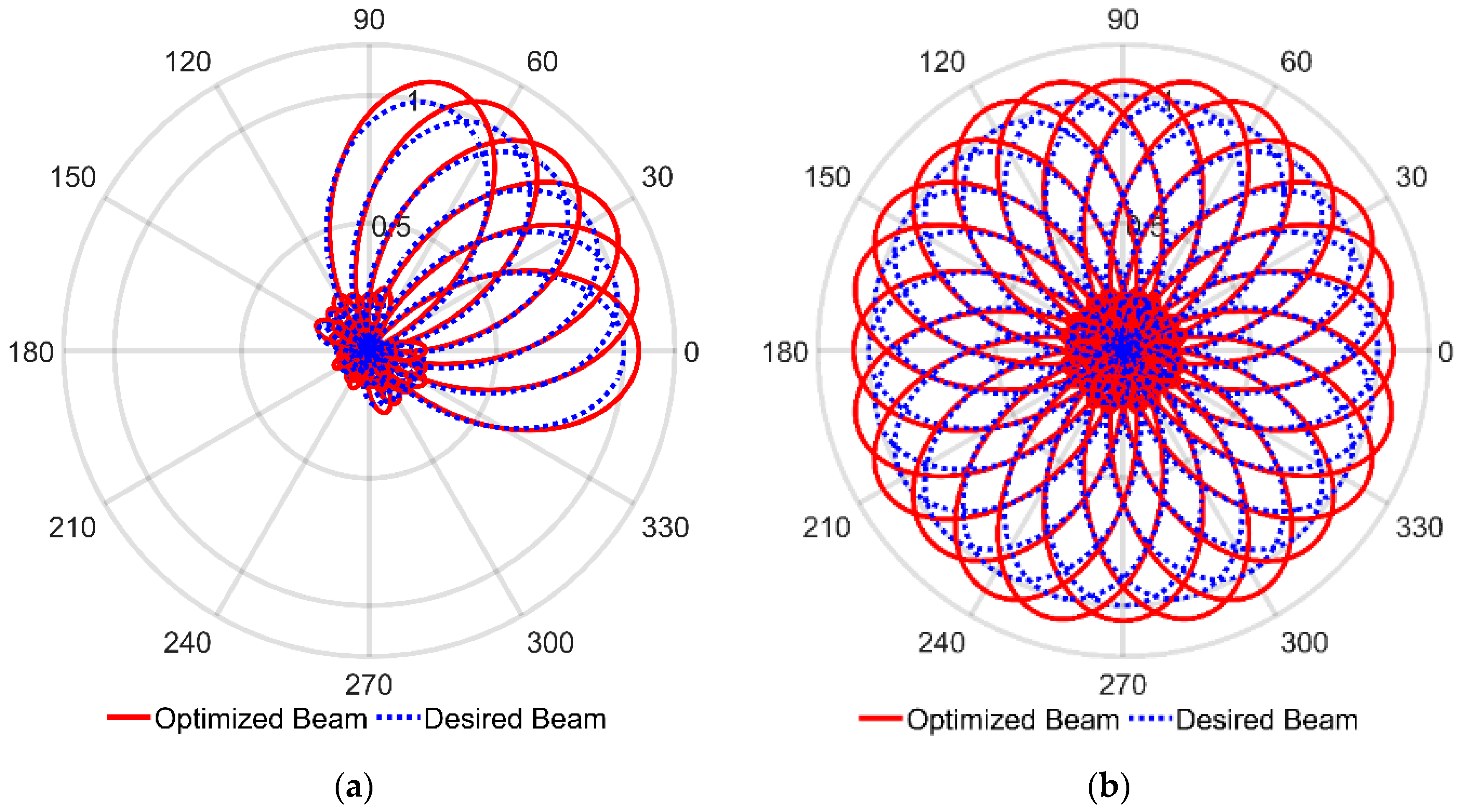
3.2. Beam Shifting at 15° Steps

It is preferred to steer the beam with 15° steps of angles in the regular octagonal configuration since there are 8 elements. Having more elements enables us to steer the beam in multiple directions with high accuracy. Having calculated the phase delay factors for 0°, 15°, and 30°, we can again steer the beam to 45°, 60°, 75°, 90°, 105°, 120°, 135°, 150°, 165°, 180°, 195°, 210°, 225°, 240°, 255°, 270°, 285°, 300°, 315°, 330°, and 345° as shown in Figure 9b. In the regular octagonal configuration, we obtained a narrower beam than the desired single beam pattern when the desired angle is 0°, 45°, 90°, 135°, 180°, 225°, 270°, and 315°. When the desired angle is at 15°, 30°, 60°, 75°, 105°, 120°, 150°, 165°, 195°, 210°, 240°, 255°, 285°, 300°, 330°, and 345°, we obtain a beam pattern that could not direct the beam towards the desired direction as shown in Figure 9b. In addition, for the specific angles, the beam-width is larger than the desired beam pattern. Overall, we obtain narrower beams than the desired beam at 0°, 45°, 90°, 135°, 180°, 225°, 270°, and 315°, with an inferior performance at 15°, 30°, 60°, 75°, 105°, 120°, 150°, 165°, 195°, 210°, 240°, 255°, 285°, 300°, 330°, and 345°. The inferior performance is due to inappropriate positioning of the dipoles in the stated configuration so the beam could not be steered to those particular angles.
Therefore, we observe that a regular octagonal configuration is not suitable for steering the beam towards all the desired directions though it has the lowest computational requirement to optimize the phase delay factors to do so.
Since the regular octagonal configuration is unsuccessful in steering the beam in all directions with a good pattern, we consider two special eight-element array configurations that are shown in Figure 10 and Figure 11. Both are named as two-square configurations. Having calculated the weight values for 0°, 15°, 30°, 45°, 60°, and 75°, we can again switch the beam to 90°, 105°, 120°, 135°, 150°, 165°, 180°, 195°, 210°, 225°, 240°, 255°, 270°, 285°, 300°, 315°, 330°, and 345° as shown in Figure 10b and Figure 11b. In both two-square configurations, we obtained a nearly perfect match to the desired beam pattern for all the angles. Therefore, we observe that we can steer the beam in steps of 15° from 0° to 360° with a nearly perfect beam with both of the two-square configurations.
In the 8-element structure, with reference to one of the dipole positions, seven different space vectors exist toward the rest of the dipole positions. Every space vector contributes a different space harmonics (phase shifts) component to direct the beam to the desired direction. The number of space harmonics (seven in number) seems to be enough with appropriate dipole positioning to perfectly direct the beam throughout any desired angle of 0° to 360°. Finally, we have shown that while increasing the number of elements and identifying the appropriate dipole positioning configuration, we can have the perfect match for every desired beam angle.
Next, we wanted to test if the two-triangular, regular octagonal, and both two-square configurations can be used to obtain single beam patterns. We have already shown that the regular hexagonal configuration and proposed two-triangular configuration can be used to obtain a nearly perfect match to the desired single beam patterns for some set of angles, while the patterns deviate from the desired pattern for another set of angles. Comparing the regular hexagonal and two-triangular configurations, the computational burden is high in the two-triangular configuration for the same set of steering angles. Hence, the regular hexagonal model is superior among these models.
In the proposed regular octagonal configuration, the beam-width is narrower with higher directivity than the desired single beam in a specific set of directions. However, the beamwidths are wider with poor alignment for another set of angles.
However, in the proposed two-square configurations, a nearly perfect beam match to the desired beam pattern is obtained for all possible angles, even though the computational burden is high. Therefore, two-square configurations are superior in performance in comparison to the regular octagonal configuration.
Next, we optimized the phase delay coefficients to steer the beam to 0°, 15°, 30°, 45°, 60°, and 75° angles for two-square configurations. This proves that the beam can be steered in steps of 15° angles from 0° to 360° almost perfectly.

3.3. Beamsteering towards an Arbitrary Angle

Finally, for practical applications, the beam has to be steered to any given angle. We have tested this on the two-square configuration 1 and two-square configuration 2 for angles 10°, 22.5°, 35°, 50°, and 70°. The results are shown in Figure 12 and Figure 13, respectively, where again an almost perfect match is achieved. Therefore, we can say that a nearly perfect match for any given angle is possible with both two-square configurations studied.

3.4. Further Observations

Table 1 and Table 2 summarize the comparisons between different nonlinear antenna array configurations used to obtain single beam smart antennas. The comparisons include critical factors such as directivity, sidelobe reduction, and the accuracy of single beam patterns. These tables demonstrate the effectiveness and advantages of the proposed configurations.
From the Tables, we observe the following. In the two-triangular configurations, better directivity and improved sidelobe reduction are observed than in previous results in the proposed configurations at certain angles; however, in some instances, a somewhat larger beam width is obtained.
Among the previously studied and newly proposed configurations, the regular octagonal configuration gives a beam with the highest directivity for a set of specified desired angles, but with poor sidelobe reduction. For the remaining set of angles, the beam is not formed at the desired angle for maximum radiation.
Both two-square configurations provide almost identical beam patterns of the desired beam, directivity, and sidelobe reduction. Among the previously proposed and newly proposed configurations, only the two-square configurations provide high directivity and improved sidelobe reduction for all angles throughout the 360° space. However, the largest directivity in regular octagonal configuration for a set of angles is greater than that of two-square configurations.
In the regular hexagonal and two-triangular configurations, the computational burden is high in the two-triangular configuration for the same set of steering angles.
In regular octagon and two-square configurations, for the same set of steering angles, the computational burden is high in two-square configurations. However, almost identical directivity and beamwidth are achieved throughout all the specified angles.
All newly proposed configurations provide higher directivity and improved sidelobe reduction compared to the previously proposed configurations. Furthermore, among the proposed models, the two-square configurations provide high directivity and improved sidelobe reduction for all the scanned angles.
Finally, we note that the physical realization of these antenna configurations might bring new challenges. Furthermore, the high-speed controllable phase delay elements may not be freely available in the market.

4. Conclusions

This paper presents multiple new antenna structures that will perform single beamforming in multiple directions on the move. Namely, two-triangular, regular octagonal, and two different two-square single beam-steering non-linear antenna array configurations are proposed for 5G and future 6G energy harvesting applications.
Using the proposed two-square configurations, we can direct the single beam to different angles from 0° to 360°. Furthermore, we have used the array antenna configurations with the multiple axes of symmetry in the azimuthal plane to avoid recalculating the weights when rotating the beams from 0° to 360°. This characteristic enables multiple directional steering of antenna beams for two-square configurations while computing the phase delay factors for only one-fourth of the required rotational angles.
Our studies show that by appropriately increasing the number of dipole elements with appropriate positioning we can achieve smart array antennas that will receive or transmit energy with high directivity and narrow beamwidth from/to any direction. Even though the regular polygon structures have the maximum number of symmetrical axes, regular polygon configurations may not be the best solution to positioning the dipoles to steer the beam throughout a 360° space. Even though, we have identified suitable configurations with 8-elements. Further study on optimal positioning of dipoles as well as extending this work to non-dipole antenna arrays is a challenging area.

Author Contributions

Conceptualization, K.P. and P.R.P.H.; Methodology, K.P. and X.F.; Software, K.P., N.A. and K.S.; Validation, K.P., N.A., K.S., X.F. and P.R.P.H.; Formal analysis, K.P., N.A., K.S., X.F. and P.R.P.H.; Investigation, K.P., N.A., K.S., X.F. and P.R.P.H.; Resources, K.P., X.F. and P.R.P.H.; Data curation, K.P., N.A. and K.S.; Writing—original draft preparation, K.P., N.A. and K.S.; Writing—review and editing, K.P., X.F. and P.R.P.H.; Visualization, K.P., N.A. and K.S.; Supervision, K.P. and P.R.P.H.; Project administration, K.P. and X.F. All authors have read and agreed to the published version of the manuscript.

Funding

This research received no external funding.

Conflicts of Interest

The authors declare no conflict of interest.

References

  1. Supriya, R.; Kumar, D.S. Adaptive Algorithms in Smart Antenna Beamformation for Wireless Communication. In Proceedings of the 2016 International Conference on Communication and Signal Processing (ICCSP), Melmaruvathur, India, 6–8 April 2016; pp. 1850–1853. [Google Scholar] [CrossRef]
  2. Tian, H.L.; Cheadle, D. An Electronically Steerable Parasitic Array Radiator Antenna with Adaptive Beamforming Ability. In Proceedings of the 2017 International Workshop on Electromagnetics: Applications and Student Innovation Competition, London, UK, 30 May–1 June 2017; pp. 103–104. [Google Scholar] [CrossRef]
  3. Agiwal, M.; Roy, A.; Saxena, N. Next Generation 5G Wireless Networks: A Comprehensive Survey. IEEE Commun. Surv. Tutorials 2016, 18, 1617–1655. [Google Scholar] [CrossRef]
  4. Salunke, D.B.; Kawitkar, R.S. Analysis of LMS, NLMS and MUSIC Algorithms for Adaptive Array Antenna System. Int. J. Eng. Adv. Technol. (IJEAT) 2013, 2, 130–133. [Google Scholar]
  5. Obaid, A.; Hussain, F.; Fernando, X. Adaptive Switching for Efficient Energy Harvesting in Energy Constraint IoT Devices. In Proceedings of the 2017 IEEE 86th Vehicular Technology Conference (VTC-Fall), Toronto, ON, Canada, 24–27 September 2017; pp. 1–5. [Google Scholar] [CrossRef]
  6. Obaid, A.; Fernando, X.; Jaseemuddin, M. A Mobility-Aware Cluster-Based MAC Protocol for Radio- Frequency Energy Harvesting Cognitive Wireless Sensor Networks. IET Wirel. Sens. Syst. 2021, 11, 206–218. [Google Scholar] [CrossRef]
  7. Kausar, A.; Mehrpouyan, H.; Sellathurai, M.; Qian, R.; Kausar, S. Energy Efficient Switched Parasitic Array Antenna for 5G Networks and IoT. In Proceedings of the 2016 Loughborough Antennas Propagation Conference (LAPC), Loughborough, UK, 14–15 November 2016; pp. 1–5. [Google Scholar] [CrossRef]
  8. Muirhead, D.; Imran, M.A.; Arshad, K. A Survey of the Challenges, Opportunities and Use of Multiple Antennas in Current and Future 5G Small Cell Base Stations. IEEE Access 2016, 4, 2952–2964. [Google Scholar] [CrossRef]
  9. Hong, W.; Jiang, Z.H.; Yu, C.; Zhou, J.; Chen, P.; Yu, Z.; Zhang, H.; Yang, B.; Pang, X.; Jiang, M.; et al. Multibeam Antenna Technologies for 5G Wireless Communications. IEEE Trans. Antennas Propag. 2017, 65, 6231–6249. [Google Scholar] [CrossRef]
  10. Chataut, R.; Akl, R. Massive MIMO Systems for 5G and Beyond Networks-Overview, Recent Trends, Challenges, and Future Research Direction. Sensors 2020, 20, 2753. [Google Scholar] [CrossRef] [PubMed]
  11. Ardi, E.M.; Shubair, R.M.; Mualla, M.E. Adaptive Beamforming Arrays for Smart Antenna Systems: A Comprehensive Performance Study. In Proceedings of the IEEE Antennas and Propagation Society Symposium, Monterey, CA, USA, 20–25 June 2004; IEEE: Piscataway, NJ, USA, 2004; Volume 3, pp. 2651–2654. [Google Scholar] [CrossRef]
  12. Singh, A.; Kumar, A.; Ranjan, A.; Kumar, A.; Kumar, A. Beam Steering in Antenna. In Proceedings of the 2017 International Conference on Innovations in Information, Embedded and Communication Systems (ICIIECS), Coimbatore, India, 17–18 March 2017; pp. 1–4. [Google Scholar] [CrossRef]
  13. Hoole, P.R.P.; Pirapaharan, K.; Hoole, S.R.H. An Electromagnetic Field Based Signal Processor for Mobile Communication Position-Velocity Estimation and Digital Beam-Forming: An Overview (Asia-Pacific Symposium on Applied Electromagnetics and Mechanics (APSAEM10)). J. Jpn. Soc. Appl. Electromagn. 2011, 19, S33–S36. [Google Scholar]
  14. Pirapaharan, K.; Kunsei, H.; Senthilkumar, K.S.; Hoole, P.R.P.; Hoole, S.R.H. A Single Beam Smart Antenna for Wireless Communication in a Highly Reflective and Narrow Environment. In Proceedings of the 2016 International Symposium on Fundamentals of Electrical Engineering (ISFEE), Bucharest, Romania, 30 June–2 July 2016; pp. 1–5. [Google Scholar] [CrossRef]
  15. Senthilkumar, K.S.; Pirapaharan, K.; Hoole, P.R.P.; Hoole, R.R.H. Single Perceptron Model for Smart Beam Forming in Array Antennas. Int. J. Electr. Comput. Eng. 2016, 6, 2300. [Google Scholar] [CrossRef]
  16. Uluisik, C. Antenna Systems with Beam Forming and Beam Steering Capabilities for HF Skywave Radars. Turkish J. Electr. Eng. Comput. Sci. 2010, 18, 485–498. [Google Scholar] [CrossRef]
  17. Bodhe, S.K.; Hogade, B.G.; Nandgaonkar, S. Beamforming Techniques for Smart Antenna Using Rectangular. Int. J. Electr. Comput. Eng. 2014, 4, 257–264. [Google Scholar] [CrossRef]
  18. Sun, Z.; Akyildiz, I.F. Optimal MIMO Antenna Geometry Analysis for Wireless Networks in Underground Tunnels. In Proceedings of the GLOBECOM 2009—2009 IEEE Global Telecommunications Conference, Honolulu, HI, USA, 30 November–4 December 2009; pp. 1–6. [Google Scholar] [CrossRef]
  19. Kulkarni, J.; Sim, C.Y.D. Wideband CPW-Fed Oval-Shapaed Monopole Antenna for Wi-Fi 5 and Wi-Fi 6 applications. Prog. Electromagn. Res. C 2021, 107, 173–182. [Google Scholar] [CrossRef]
  20. Kulkarni, J.; Abdullah, G.A.; Desai, A.; Sim, C.Y.D.; Poddar, A. Design and Analysis of Wideband Flexible Self-Isolating MIMO Antennas for Sub-6 5G and WLAN Smartphone Terminals. Electronics 2021, 10, 3031. [Google Scholar] [CrossRef]
  21. Pirapaharan, K.; Hoole, P.R.P.; Kumsei, H.; Senthilkumar, K.S.; Hoole, S.R. A New Smart Antenna for 5/6G Wireless Systems: Narrow 360° Steerable Beam With No Reflectors. In Smart Antennas and Electromagnetic Signal Processing for Advanced Wireless Technology: With Artificial Intelligence Applications and Coding; River Publishers: Gistrup, Denmark, 2020; pp. 147–166. [Google Scholar]
  22. Widrow, B.; Mantey, P.E.; Griffiths, L.J.; Goode, B.B. Adaptive Antenna Systems. Proc. IEEE 1967, 55, 2143–2159. [Google Scholar] [CrossRef]
  23. Griffiths, L.J. A Simple Adaptive Algorithm for Real Time Processing in Antenna Arrays. Proc. IEEE 1969, 57, 1696–1704. [Google Scholar] [CrossRef]
Figure 1. Schematic Diagram of Array Models proposed in [14] (a) Equilateral Triangular Configuration, (b) Square Configuration, and (c) Regular Hexagonal Configuration.
Electronics 11 02658 g001aElectronics 11 02658 g001b
Figure 2. Schematic Diagram of the Proposed Two-Triangular Configuration.
Electronics 11 02658 g002
Figure 3. Schematic Diagram of the Proposed Regular Octagonal Configuration.
Electronics 11 02658 g003
Figure 4. Schematic Diagram of the Proposed Two-Square Configuration 1.
Electronics 11 02658 g004
Figure 5. Schematic Diagram of the Proposed Two-Square Configuration 2.
Electronics 11 02658 g005
Figure 6. Schematic diagram of dipole placement in a regular polygon.
Electronics 11 02658 g006
Figure 7. Beam Patterns of Regular Hexagonal Configuration: (a) Beam to 0° and 30°, (b) Rotated beams.
Electronics 11 02658 g007
Figure 8. Beam Patterns of Two-Triangular Configuration: (a) Beam to 0°, 30°, 60°, and 90°, (b) Rotated beams.
Electronics 11 02658 g008
Figure 9. Beam Patterns of Regular Octagonal Configuration: (a) Beam to 0°, 15°, and 30°, (b) Rotated beams.
Electronics 11 02658 g009
Figure 10. Beam Patterns of Two-Square Configuration 1: (a) Beam to 0°, 15°, 30°, 45°, 60°, and 75°, (b) Rotated beams.
Electronics 11 02658 g010
Figure 11. Beam Patterns of Two-Square Configuration 2: (a) Beam to 0°, 15°, 30°, 45°, 60°, and 75°, (b) Rotated beams.
Electronics 11 02658 g011
Figure 12. Beam Patterns of Two-Square Configuration 1: (a) Beam to random angles 10°, 22.5°, 35°, 50°, and 70°, (b) Rotated beams.
Electronics 11 02658 g012
Figure 13. Beam Patterns of Two-Square Configuration 2: (a) Beam to random angles 10°, 22.5°, 35°, 50°, and 70°, (b) Rotated beams.
Electronics 11 02658 g013
Table 1. Directivity, Sidelobe Reduction and Single Beam Patterns for the Array Models proposed in [14], where the blue and read lines are showing the desired beam and optimized beam patterns, respectively.
ConfigurationsOptimized AngleMaximum DirectivitySidelobe ReductionSingle Beam Patterns
Equilateral Triangular2.88 at −0.09°0.38 with the sidelobe located at 138.56° Electronics 11 02658 i001
30°3.09 at 29.91°0.73 with the sidelobe located at −150.00° Electronics 11 02658 i002
60°2.89 at 59.91°0.41 with the sidelobe located at −76.46° Electronics 11 02658 i003
90°3.10 at 89.91°0.70 with the sidelobe located at −90.18° Electronics 11 02658 i004
Square5.09 at −0.09°0.31 with the sidelobe located at 180.00° Electronics 11 02658 i005
30°3.95 at 12.15°0.56 with the sidelobe located at −128.2276° Electronics 11 02658 i006
60°3.95 at 77.67°0.56 with the sidelobe located at −141.38° Electronics 11 02658 i007
Regular Hexagonal6.42 at −0.09°0.08 with the sidelobe located at −133.02° Electronics 11 02658 i008
30°5.06 at 29.91°0.12 with the sidelobe located at −150.00° Electronics 11 02658 i009
Table 2. Directivity, Sidelobe Reduction and Single Beam Patterns for the newly proposed Array Models, where the blue and read lines are showing the desired beam and optimized beam patterns, respectively.
ConfigurationsOptimized AngleMaximum DirectivitySidelobe ReductionSingle Beam Patterns
Two-Triangular5.23 at −0.09°0.05 with the sidelobe located at −107.81° Electronics 11 02658 i010
30°6.75 at 29.91°0.05 with the sidelobe located at 106.69°
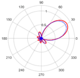
 Electronics 11 02658 i011
60°5.23 at 59.91°0.06 with the sidelobe located at 168.77° Electronics 11 02658 i012
90°6.75 at 89.91°0.05 with the sidelobe located at 13.13°
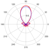
 Electronics 11 02658 i013
Regular Octagonal7.78 at −0.09°0.13 with the sidelobe located at 70.38°
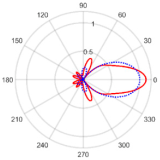
 Electronics 11 02658 i014
15°6.84 at 6.89°0.14 with the sidelobe located at −66.45° Electronics 11 02658 i015
30°6.85 at 38.50°0.14 with the sidelobe located at 111.27° Electronics 11 02658 i016
Two-Square 16.94 at −0.09°0.06 with the sidelobe located at −75.1487° Electronics 11 02658 i017
15°7.07 at 15.85°0.05 with the sidelobe located at −62.44° Electronics 11 02658 i018
30°7.10 at 29.84°0.04 with the sidelobe located at 107.26° Electronics 11 02658 i019
45°6.92 at 44.91°0.06 with the sidelobe located at −30.72°
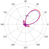
 Electronics 11 02658 i020
60°7.08 at 60.48°0.05 with the sidelobe located at −17.44° Electronics 11 02658 i021
75°7.08 at 74.76°0.05 with the sidelobe located at 152.26° Electronics 11 02658 i022
Publisher’s Note: MDPI stays neutral with regard to jurisdictional claims in published maps and institutional affiliations.

