
A Modified Modulation Strategy for an Active Neutral-Point-Clamped Five-Level Converter in a 1500 V PV System

Abstract
:1. Introduction
2. Traditional Modulation Strategy
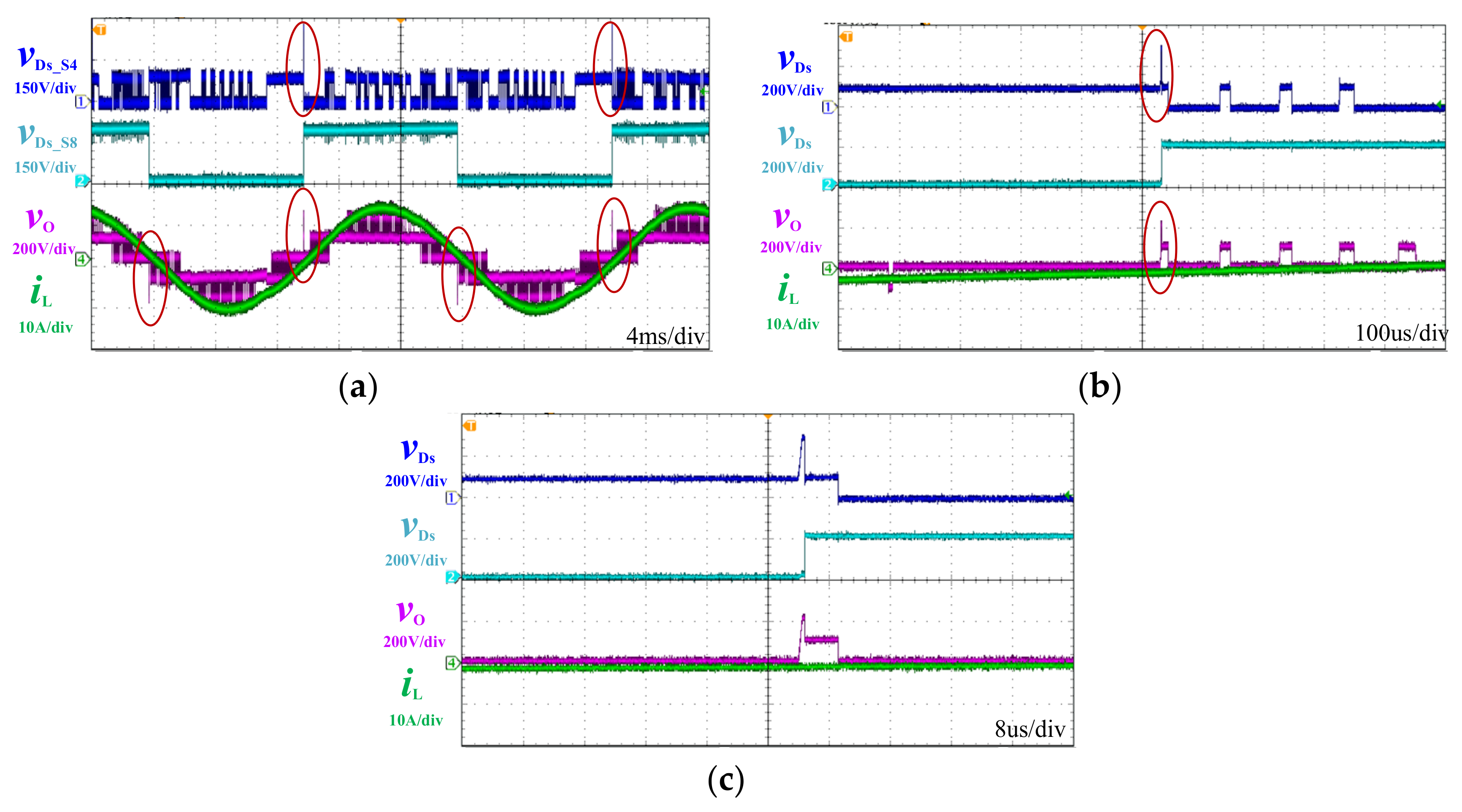
3. Overvoltage Issue of Traditional Modulation
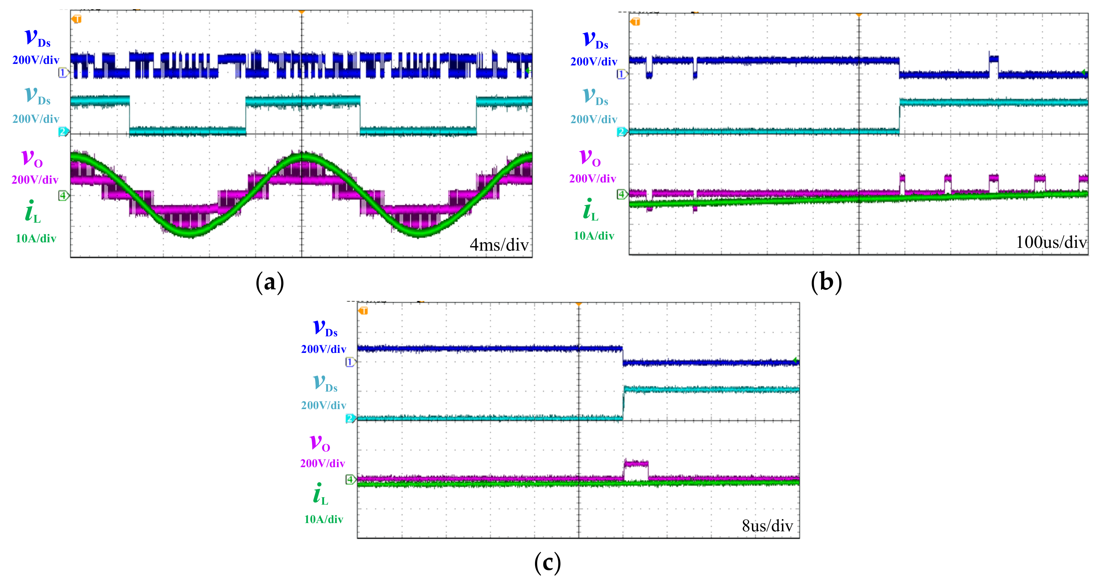
4. Proposed Modified Modulation Strategy
- A.
- Flying capacitor voltage balance
- B.
- Commutation
- 1.
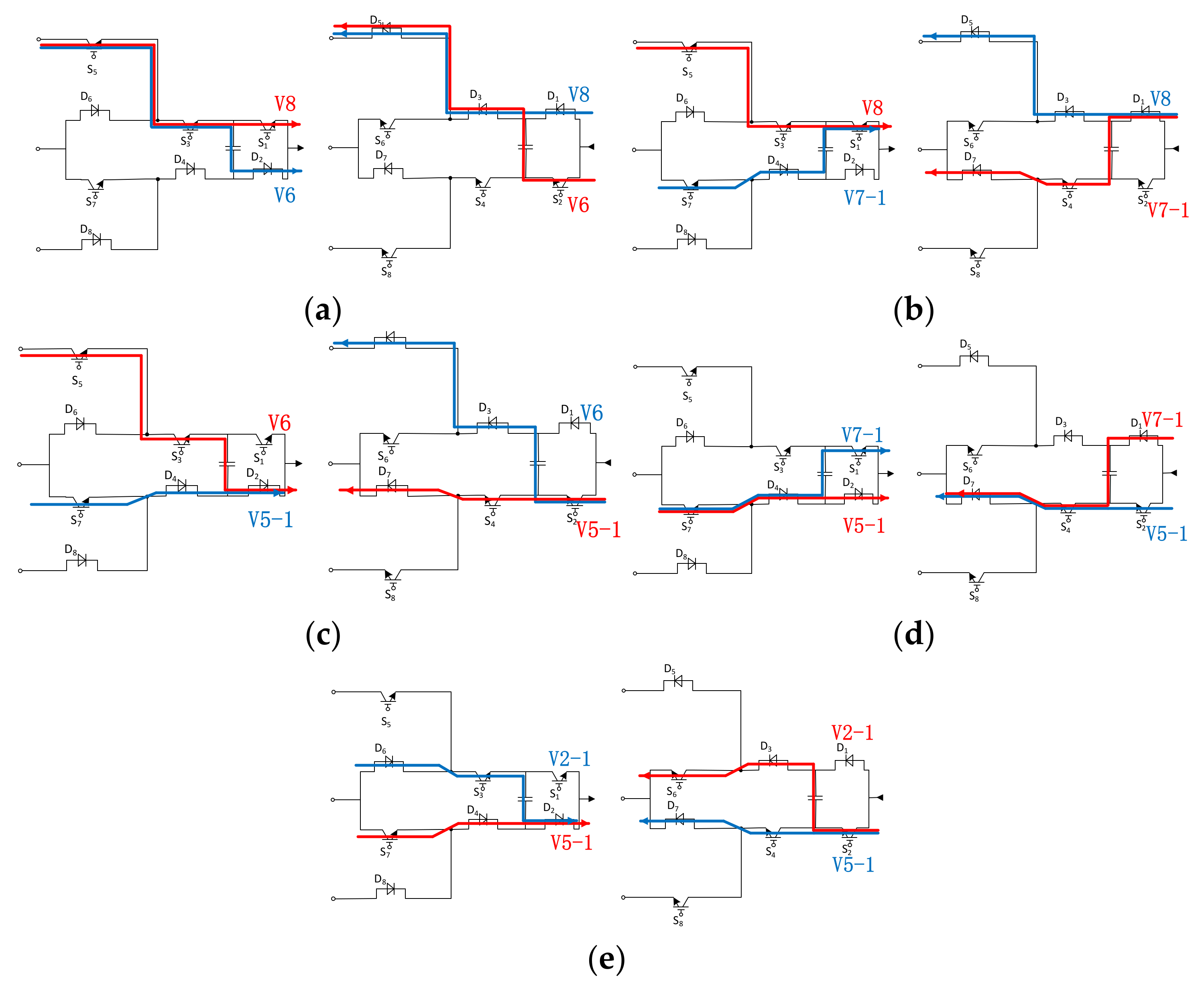
- V8 to V6: As shown in Figure 13a, S1 is turned off and after the turn-off delay S2 is turned on. Moreover, with the positive phase current, the state change, current commutation and switching loss occurs at S1 OFF. In contrast, with the negative phase current, the commutation of current and switching loss occurs at S2 ON;
- 2.
- V8 to V7-1: As shown in Figure 13b, it is inevitable to turn off S3 and turn on S4. If the phase current is positive, the commutation of current and switching loss occurs at S3 OFF;
- 3.
- V6 to V5-1: As shown in Figure 13c, it is inevitable to turn off S3 and turn on S4,and if the phase current is positive, the commutation of current and switching loss occurs at S3 OFF;
- 4.
- V5-1 to V7-1: As shown in Figure 13d, it is inevitable to turn off S2 and turn on S1;
- 5.
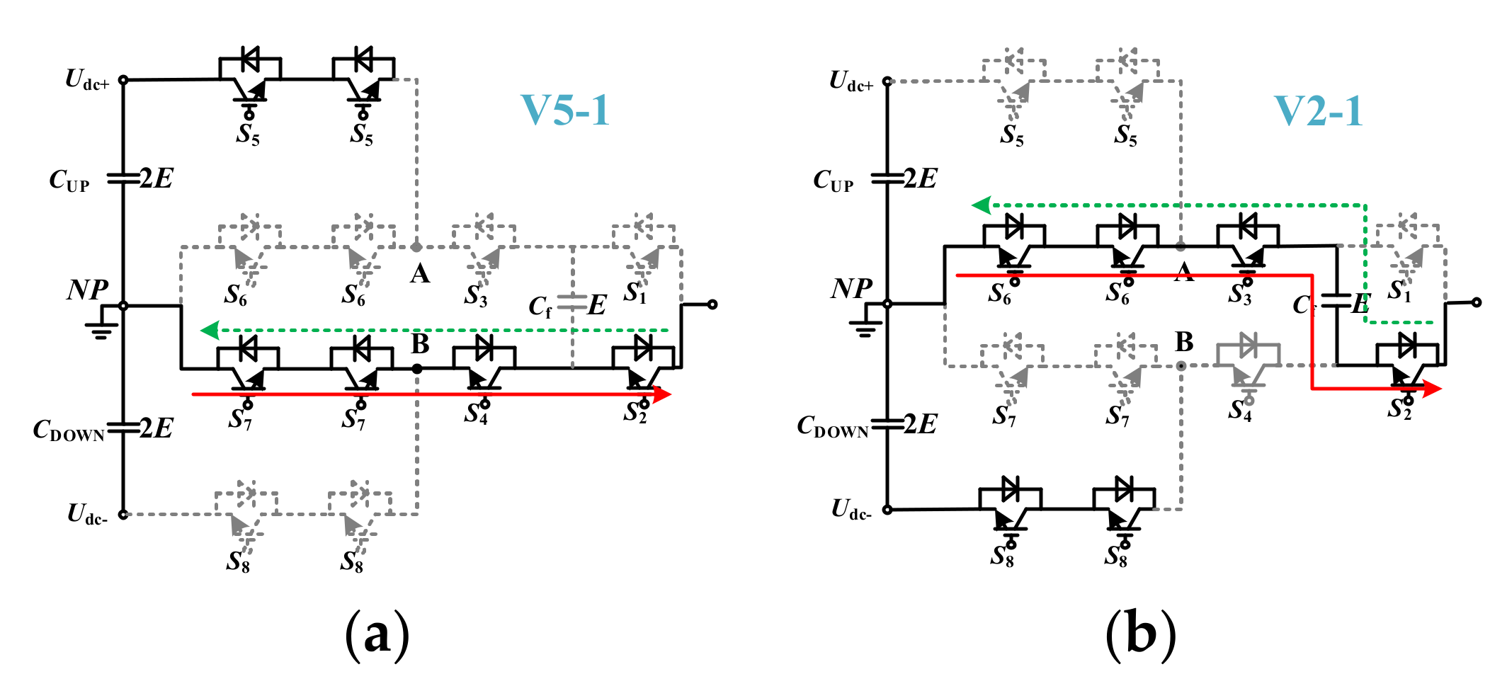
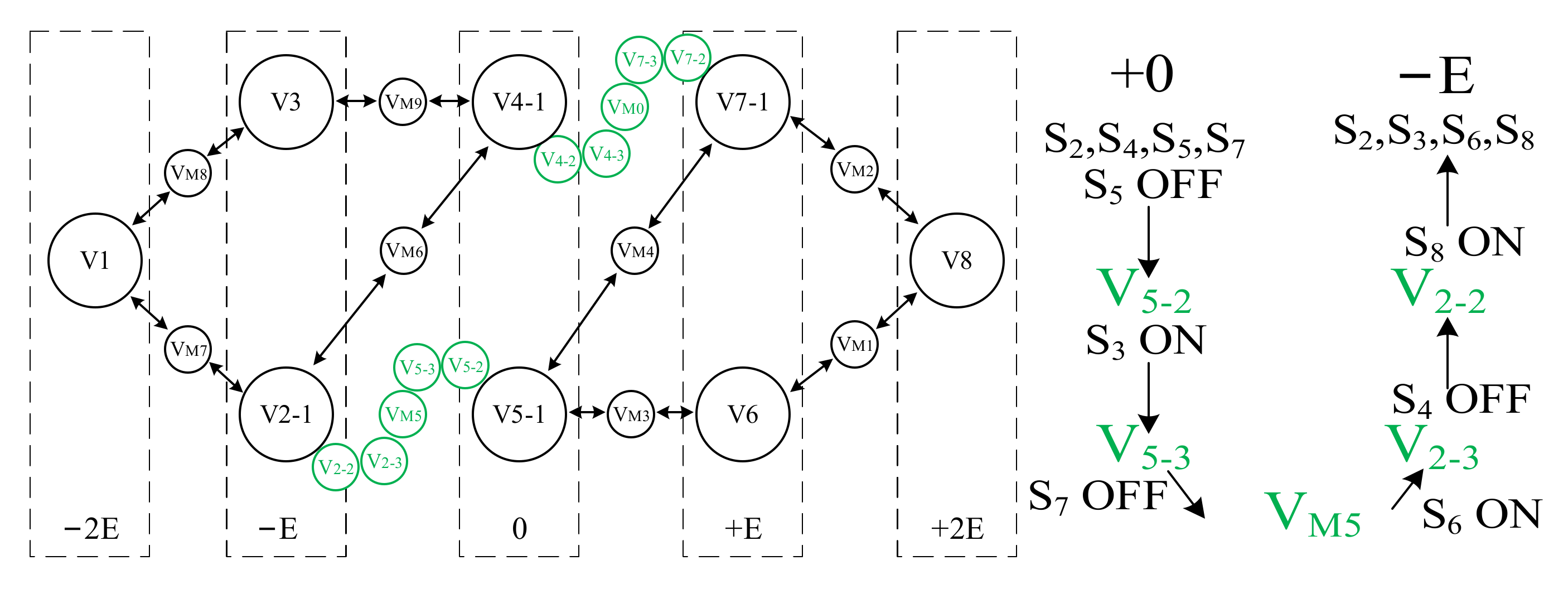
- V5-1 to V2-1: As shown in Figure 13e, it is inevitable to turn off S5, S7, and S4 and turn on S3, S6, and S8 in the cutover from V5-1 to V2-1. If the phase current is negative, the middle state VM5 generates zero voltage level, not −E voltage level.
5. Proposed Control Method for Soft Start-Up
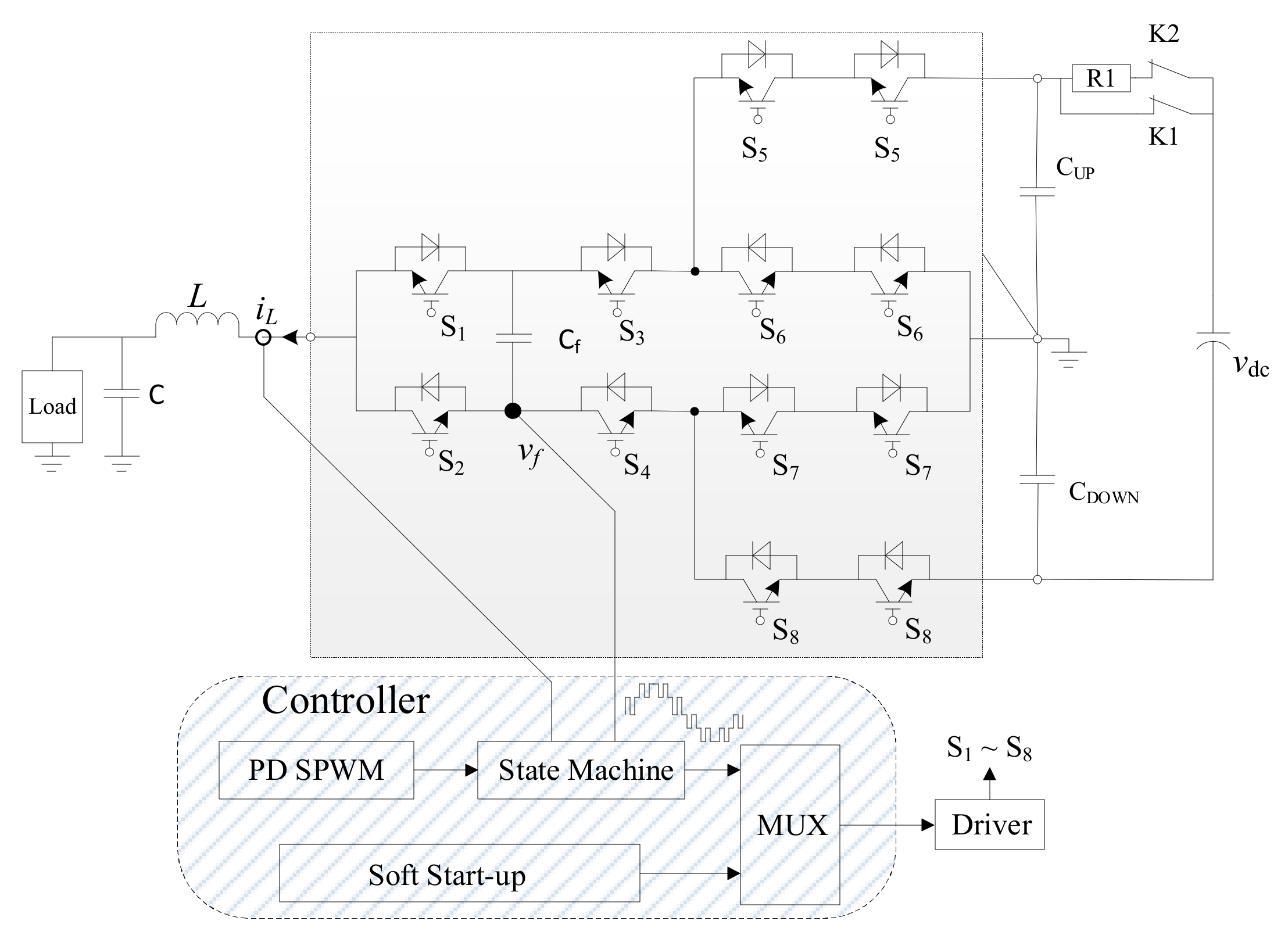
- State 1: When the upper bus capacitance CUP and the lower bus capacitance CDOWN are zero, and the flying capacitor Cf is not charged and the contactors K1 and K2 are disconnected, the ANPC five-level single-phase converter is in the initial condition with no energy in the capacitors. As shown in Figure 15a, since the main switches S3, S4, S5 and S8 are turned on and the contactor K2 is connected, the DC-link voltage source charges the upper bus capacitor CUP, the lower bus capacitor CDOWN, and the flying capacitor Cf simultaneously through the current limiting resistance R1. The voltage-divider resistances, R2 and R3, are placed in parallel with each bus capacitor to avoid the influence of the unbalanced characteristics of the upper and lower bus capacitors. In Figure 15d, the voltage of the flying capacitor Cf and bus capacitors increases gradually from t1 to t2;
- State 2: Until the voltage of Cf arrives at E, a quarter of the total bus voltage and power devices S3, S4, S5 and S8 are turned off and the voltage of bus capacitors will be half of flying capacitor voltage. Thus, the voltage stress of power switches is not higher than VDC/4 in the entire stage, which meets its request. As shown in Figure 15b, the DC-link capacitors are going to be charged by the DC-link voltage source at the same time with the voltage divider resistances in parallel with each bus capacitor to avoid the influence of the unbalanced characteristics of the bus capacitors;
- State 3: The voltage of CUP and CDOWN increases gradually until they reach their reference value 2E, as shown in Figure 15d from t2 to t3. When CUP and CDOWN are fully charged, the contactor K1 is connected and K2 is disconnected. Then, the ANPC five-level single-phase converter starts up well with enough energy in the capacitors, as shown in Figure 15c and is ready to work.
6. Experimental Results
7. Conclusions
Author Contributions
Funding
Conflicts of Interest
References
- Pires, V.F.; Cordeiro, A.; Foito, D.; Pires, A.J.; Hao, C.; Martins, J.F.; Castro, R. Compensation of Unbalanced Low-Voltage Grids Using a Photovoltaic Generation System with a Dual Four-Leg, Two-Level Inverter. Electronics 2022, 11, 320. [Google Scholar] [CrossRef]
- Gkoutioudi, E.; Bakas, P.; Marinopoulos, A. Comparison of PV systems with maximum DC voltage 1000 V and 1500 V. In Proceedings of the Photovoltaic Specialists Conference (PVSC), Tampa Bay, FL, USA, 16–21 June 2013; pp. 2873–2878. [Google Scholar]
- Čorba, Z.; Popadić, B.; Katić, V.; Dumnić, B.; Milićević, D. Future of high power PV plants—1500 V inverters. In Proceedings of the 19th International Symposium on Power Electronics (Ee), Novi Sad, Serbia, 19–21 October 2017; pp. 1–5. [Google Scholar]
- Stevanovic, B.; Serban, E.; Cobreces, S.; Alou, P.; Ordonez, M.; Vasic, M. DC/DC Stage Contribution to Bus Voltage in 1000 V and 1500 V Grid-Connected Solar Inverters. IEEE J. Emerg. Sel. Top. Power Electron. 2022, 1. [Google Scholar] [CrossRef]
- Serban, E.; Ordonez, M.; Pondiche, C. DC-bus voltage range extension in 1500 V photovoltaic inverters. IEEE J. Emerg. Sel. Top. Power Electron. 2015, 3, 901–917. [Google Scholar] [CrossRef]
- Prathaban, A.V.; Dhandapani, K.; Abubakar, A.I.S. Compact Thirteen-Level Inverter for PV Applications. Energies 2022, 15, 2808. [Google Scholar] [CrossRef]
- Gupta, K.K.; Ranjan, A.; Bhatnagar, P.; Sahu, L.K.; Jain, S. Multilevel Inverter Topologies with Reduced Device Count: A Review. IEEE Trans. Power Electron. 2016, 31, 135–151. [Google Scholar] [CrossRef]
- Campanhol, L.B.G.; da Silva, S.A.O.; de Oliveira, A.A.; Bacon, V.D. Dynamic Performance Improvement of a Grid-Tied PV System Using a Feed-Forward Control Loop Acting on the NPC Inverter Currents. IEEE Trans. Ind. Electron. 2017, 64, 2092–2101. [Google Scholar] [CrossRef]
- Busquets-Monge, S. A Simple Virtual-Vector-Based PWM Formulation for Multilevel Three-Phase Neutral-Point-Clamped DC–AC Converters including the Overmodulation Region. Electronics 2022, 11, 641. [Google Scholar] [CrossRef]
- Gonzalez, R.; Gubía, E.; Lopez, J.; Marroyo, L. Transformerless Single-Phase Multilevel-Based Photovoltaic Inverter. IEEE Trans. Ind. Electron. 2008, 55, 2694–2702. [Google Scholar] [CrossRef]
- Schweizer, M.; Kolar, J.W. Design and Implementation of a Highly Efficient Three-Level T-Type Converter for Low-Voltage Applications. IEEE Trans. Power Electron. 2013, 28, 899–907. [Google Scholar] [CrossRef]
- Gateau, G.; Fadel, M.; Maussion, P.; Bensaid, R.; Meynard, T. Multicell converters: Active control and observation of flying-capacitor voltages. IEEE Trans. Ind. Electron. 2002, 49, 998–1008. [Google Scholar] [CrossRef]
- Choi, U.-M.; Ryu, T. Comparative Evaluation of Efficiency and Reliability of Single-Phase Five-Level NPC Inverters for Photovoltaic Systems. IEEE Access 2021, 9, 120638–120651. [Google Scholar] [CrossRef]
- Fazel, S.; Bernet, S.; Krug, D.; Jalili, K. Design and comparison of 4-kV neutral-point-clamped, flying-capacitor, and series-connected H-bridge multilevel converters. IEEE Trans. Ind. Appl. 2007, 43, 1032–1040. [Google Scholar] [CrossRef]
- Ghias, A.M.Y.M.; Pou, J.; Acuna, P.; Ceballos, S.; Heidari, A.; Agelidis, V.G.; Merabet, A. Elimination of Low-Frequency Ripples and Regulation of Neutral-Point Voltage in Stacked Multicell Converters. IEEE Trans. Power Electron. 2017, 32, 164–175. [Google Scholar] [CrossRef]
- Gutierrez, E.; Kouro, S.; Rojas, C.A.; Aguirre, M. Predictive control of an h-npc converter for single-phase rooftop photovoltaic systems. In Proceedings of the Energy Conversion Congress and Exposition (ECCE), Montreal, QC, Canada, 20–24 September 2015; pp. 3295–3302. [Google Scholar]
- Tian, K.; Wu, B.; Narimani, M.; Xu, D.; Cheng, Z.; Zargari, N.R. A Capacitor Voltage-Balancing Method for Nested Neutral Point Clamped (NNPC) Inverter. IEEE Trans. Power Electron. 2016, 31, 2575–2583. [Google Scholar] [CrossRef]
- Barbosa, P.; Steimer, P.; Steinke, J.; Winkelnkemper, M.; Celanovic, N. Active-neutral-point-clamped (ANPC) multilevel converter technology. In Proceedings of the European Conference on Power Electronics and Applications, Dresden, Germany, 11–14 September 2005; p. 10. [Google Scholar] [CrossRef]
- Guo, W.; Li, R.; Yang, J.; Cao, Y. Circulating Current Suppression Scheme for Interleaved Active Neutral Point Clamped Nine-Level Inverter. IEEE J. Emerg. Sel. Top. Power Electron. 2022, 1. [Google Scholar] [CrossRef]
- Lee, S.S.; Yang, Y.; Siwakoti, Y.P. A Novel Single-Stage Five-Level Common-Ground-Boost-Type Active Neutral-Point-Clamped (5L-CGBT-ANPC) Inverter. IEEE Trans. Power Electron. 2021, 36, 6192–6196. [Google Scholar] [CrossRef]
- Sadigh, A.K.; Dargahi, V.; Naderi, R.; Corzine, K.A. Active Voltage Balancing and Thermal Performance Analysis of Dual Flying-Capacitor Active Neutral-Point-Clamped (DFC-ANPC) Inverters. IEEE Trans. Ind. Appl. 2021, 57, 637–649. [Google Scholar] [CrossRef]
- Burguete, E.; Lopez, J.; Zabaleta, M. A New Five-Level Active Neutral-Point-Clamped Converter with Reduced Overvoltages. IEEE Trans. Ind. Electron. 2016, 63, 7175–7183. [Google Scholar] [CrossRef]
- Liu, Z.; Wang, Y.; Tan, G.; Li, H.; Zhang, Y. A novel svpwm algorithm for five-level active neutral-point-clamped converter. IEEE Trans. Power Electron. 2016, 31, 3859–3866. [Google Scholar] [CrossRef]
- Kieferndorf, F.; Basler, M.; Serpa, L.A.; Fabian, J.-H.; Coccia, A.; Scheuer, G.A. ANPC-5L technology applied to medium voltage variable speed drives applications. In Proceedings of the SPEEDAM 2010, Pisa, Italy, 14–16 June 2010; pp. 1718–1725. [Google Scholar]
- Yang, J.; Yang, S.; Li, R. A novel and reliable modulation strategy for active neutral-point clamped five-level converter. In Proceedings of the IEEE 3rd International Future Energy Electronics Conference and ECCE Asia (IFEEC 2017-ECCE Asia), Kaohsiung, Taiwan, 3–7 June 2017; pp. 1162–1167. [Google Scholar]
- Hong, F.; Liu, M.; Ji, B.; Wang, C. A capacitor voltage buildup method for flying capacitor multilevel Inverters. Proc. CSEE 2012, 32, 17–23. [Google Scholar]


| State | S1 | S2 | S3 | S4 | S5 | S6 | S7 | S8 | Vo | Vcf | |
|---|---|---|---|---|---|---|---|---|---|---|---|
| Io > 0 | Io < 0 | ||||||||||
| V1 | 0 | 1 | 0 | 1 | 0 | 1 | 0 | 1 | −2E | - | - |
| V2-1 | 0 | 1 | 1 | 0 | 0 | 1 | 0 | 1 | −1E | C | D |
| V3 | 1 | 0 | 0 | 1 | 0 | 1 | 0 | 1 | −1E | D | C |
| V4-1 | 1 | 0 | 1 | 0 | 0 | 1 | 0 | 1 | −0 | - | - |
| V5-1 | 0 | 1 | 0 | 1 | 1 | 0 | 1 | 0 | +0 | - | - |
| V6 | 0 | 1 | 1 | 0 | 1 | 0 | 1 | 0 | +1E | D | C |
| V7-1 | 1 | 0 | 0 | 1 | 1 | 0 | 1 | 0 | +1E | C | D |
| V8 | 1 | 0 | 1 | 0 | 1 | 0 | 1 | 0 | +2E | - | - |
| State | Sx1–Sx8 | Vcf | Vox | Level | |
|---|---|---|---|---|---|
| Io > 0 | Io < 0 | ||||
| V1 | 01010101 | − | − | −Vdc/2 | −2 |
| V2-1 | 01100101 | C a | D | −Vdc/4 | −1 |
| V2-2 | 01100100 | ||||
| V2-3 | 01110100 | ||||
| V3 | 10010101 | D | C | −Vdc/4 | −1 |
| V4-1 | 10100101 | − | − | 0 | 0 |
| V4-2 | 10100100 | ||||
| V4-3 | 10110100 | ||||
| V5-1 | 01011010 | − | − | 0 | 0 |
| V5-2 | 01010010 | ||||
| V5-3 | 01110010 | ||||
| V6 | 01101010 | D | C | Vdc/4 | 1 |
| V7-1 | 10011010 | C | D | Vdc/4 | 1 |
| V7-2 | 10010010 | ||||
| V7-3 | 10110010 | ||||
| V8 | 10101010 | − | − | Vdc/2 | 2 |
| Parameters | Values |
|---|---|
| Inverter DC-bus voltage | 400 V |
| Output frequency | 50 Hz |
| Converter rating | 1 kVA |
| Switching frequency | 10 kHz |
| Inductance of filter | 0.3 mH |
| Capacitance of DC-link capacitor | 2 mF |
| Capacitance of flying capacitor | 660 μF |
Publisher’s Note: MDPI stays neutral with regard to jurisdictional claims in published maps and institutional affiliations. |
© 2022 by the authors. Licensee MDPI, Basel, Switzerland. This article is an open access article distributed under the terms and conditions of the Creative Commons Attribution (CC BY) license (https://creativecommons.org/licenses/by/4.0/).
Share and Cite
Chen, G.; Yang, J. A Modified Modulation Strategy for an Active Neutral-Point-Clamped Five-Level Converter in a 1500 V PV System. Electronics 2022, 11, 2289. https://doi.org/10.3390/electronics11152289
Chen G, Yang J. A Modified Modulation Strategy for an Active Neutral-Point-Clamped Five-Level Converter in a 1500 V PV System. Electronics. 2022; 11(15):2289. https://doi.org/10.3390/electronics11152289
Chicago/Turabian StyleChen, Guodong, and Jiatao Yang. 2022. "A Modified Modulation Strategy for an Active Neutral-Point-Clamped Five-Level Converter in a 1500 V PV System" Electronics 11, no. 15: 2289. https://doi.org/10.3390/electronics11152289
APA StyleChen, G., & Yang, J. (2022). A Modified Modulation Strategy for an Active Neutral-Point-Clamped Five-Level Converter in a 1500 V PV System. Electronics, 11(15), 2289. https://doi.org/10.3390/electronics11152289