Abstract
This paper presents a novel design of a modified ultrawideband (UWB) antenna array integrated with a multimode resonator bandpass filter. First, a single UWB antenna is modified and studied, using a P-shape radiated patch instead of a full elliptical patch, for wide impedance bandwidth and high realized gain. Then, a two-element UWB antenna array is developed based on this modified UWB antenna with an inter-element spacing of 0.35 λL, in which λL is the free space wavelength at the lower UWB band edge of 3.1 GHz, compared to 0.27 λL of a reference UWB antenna array designed using a traditional elliptical patch shape. The partial ground plane is designed with a trapezoidal angle to enhance matching throughout the UWB frequency range. The mutual coupling reduction of a modified UWB antenna array enhances the reflection coefficient, bandwidth, and realized gain, maintaining the same size of 1.08 λ0 × 1.08 λ0 × 0.035 λ0 at 6.5 GHz center frequency as that of the reference UWB antenna array. The UWB antenna array performance is investigated at different inter-element spacing distances between the radiated elements. To add filtering capability to the UWB antenna array and eliminate interference from the out-of-band frequencies, a multimode resonator (MMR) bandpass filter (BPF) is incorporated in the feedline while maintaining a compact size. The measurement results showed a close agreement with simulated results. The proposed UWB filtering antenna array design achieved a wide fractional bandwidth of more than 109.87%, a high realized gain of more than 7.4 dBi, and a compact size of 1.08 λ0 × 1.08 λ0 × 0.035 λ0 at 6.5 GHz center frequency. These advantages make the proposed antenna suitable for UWB applications such as indoor tracking, radar systems and positioning applications.
1. Introduction
The ultrawideband technology, since it was introduced by the Federal Communication Commission (FCC) [1], has been applied for many wireless applications such as Unmanned Aerial Vehicle (UAV) systems [2], sensing and medical applications [3], weather radar application [4], indoor localization systems [5], wireless body area networks (WBANs) [6] and the Internet of Things (IoT) [7]. This is because of its attractive benefits of low cost, high data rate, and wide operating bandwidth [8,9]. Despite the widespread use of ultrawideband (UWB) applications, they face challenges related to interference with adjacent wireless systems, low resolution, and degradation of radiation characteristics in the upper portion of UWB spectrum.
To overcome these limitations, enhancement of the RF front-end of the wireless communication system is considered by integrating filter elements in the antenna design to simultaneously achieve radiation and filtering. Contrary to traditional designs of filters and antennas connected using external cables, recent studies have proposed the integration of the two components as a single unit. Thus, the losses, cost, and size associated with the extra impedance transformation elements are reduced [10,11].
Integrated filtering antennas, with radiation and filtering functions achieved, have been reported in [12,13,14,15,16,17,18,19,20,21]. However, their operating impedance bandwidth is typically narrow, and they are unable to operate throughout the entire UWB frequency spectrum. In addition to limitations in bandwidth, the filtering antennas reported in [12,13,14,15,16,20,21] are implemented using multi-layered structures, which reduces the space efficiency for practical modern wireless communication applications. To overcome this, single-layered UWB antennas integrated with bandpass filters have been proposed in [22,23,24,25]. Despite featuring ultrawide impedance bandwidths and compact sizes, these designs are applied on single antenna elements with low peak gains, which are limited to 4.25 dBi, 5.2 dBi, 4 dBi, and 4 dBi, respectively.
To improve radiation characteristics, several studies have adopted an array configuration with wideband [26,27] and UWB [28,29] operating frequency spectrum. However, these studies do not include filter design with wideband and UWB antenna arrays; hence, they suffer from interference. On the other hand, several other researchers have integrated an antenna array with a bandpass filter to form a filtering antenna array as reported in [30,31,32,33,34,35], but the maximum and minimum fractional operating bandwidth is 88.76% [31] and 3% [35], respectively.
Different bandpass filtering design techniques have been adopted in antenna arrays and reported in the literature. Several instances include the stub-loaded resonator (SLR)-based feeding network [30], feeding network based on microstrip and slotline transitions [31], filtering by using feedline and patches coupling [32], symmetrical stepped impedance resonators [33], ring slot-coupled feeding structure with Jerusalem cross radiating element [34], and power divider connected with two baluns [35]. However, the passbands of these filtering elements are narrow and limited to a maximum passband of 88.76% [31]. In addition, the filtering structure in [30] requires multi-layered configuration, whereas other researchers in [33] and [34] implemented multiple ports with multi-layered structures. These features increase the size and complexity of the filtering and consequently the overall antenna structure.
To simultaneously enable the features of wide impedance bandwidth, filtering function, and good radiation characteristics, a new class of integrated UWB antenna array is proposed. Specifically, a multimode resonator-based bandpass filter consisting of two interdigital-coupled lines and single-wing stub is designed and implemented on the proposed antenna array. This filtering configuration supports an ultrawide operation with a fractional passband of more than 120% and a compact size of 0.58 × 0.47 × 0.036 λ0. Moreover, this filtering structure is designed using a single feedline and implemented on a single layer, which ensures size compactness and simplifies its integration with the UWB antenna array. Finally, when integrated on an antenna array, this method resulted in an enhanced peak gain of up to 7.4 dBi and a fractional bandwidth of higher than 109.8%, which is centred at 6.5 GHz with a compact size of 1.08 × 1.08 × 0.035 λ0. Figure 1 summarizes the difference between the traditional and proposed design approach in the RF front-end architecture. The paper is organized as follows. First, the modified designs of a single element UWB antenna and two-element UWB array antenna are designed and studied in Section 2. The design, simulation, and testing of a UWB single-wing bandpass filter and integrated modified UWB antenna array and single-wing bandpass filter are presented in Section 3. Finally, the conclusions in this work are drawn in Section 4.
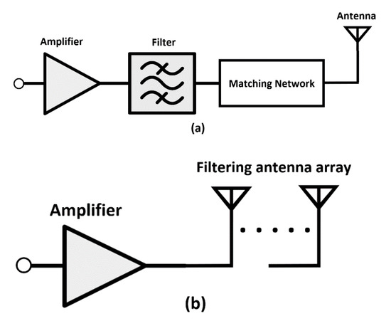
Figure 1.
RF front-end architecture (a) Traditional design approach; (b) Proposed design approach.
2. UWB Antenna Design
In this work, a reference UWB antenna array is first designed. This is followed by a small-sized UWB single-wing filter being embedded in the modified UWB antenna array to arrive at the final compact-sized UWB filtering antenna array.
2.1. Single Patch UWB Antenna
The design procedure begins with a traditional elliptical monopole antenna, as shown in Figure 2a. The lower band-edge frequency is estimated using design equations for an equivalent cylindrical monopole antenna in [36], as follows:
where H is the height of the planar monopole antenna and r is the radius of equivalent the cylindrical monopole antenna. Parameter G is the gap between the patch and the partial ground plane, and it is calculated using . All units in Equation (1) are in millimeters. Parameter is the factor that represents the effect of the substrate dielectric constant, and it is around 1.15. Parameters H and r for the patch of the planar monopole shown in Figure 2a can be obtained by using Equations (2) and (3), respectively, as follows.
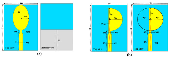
Figure 2.
Geometry of a single UWB antenna, (a) reference UWB (ultrawideband) antenna, and (b) modified patch UWB antenna.
For the P-shaped patch monopole shown in Figure 2b, the height, H, is also equal to , whereas the radius, r is equal to . Thus, the lower band-edge frequency of the P-shaped patch monopole antenna can be estimated using Equation (4). On the other hand, the upper cutoff frequency can be determined by the filter, which selects the operating band and rejects unwanted frequency bands. All units in this equation are also in millimeters.
The feedline of the elliptical monopole antenna can be calculated using Equation (5) [37]. The antenna Roger RO4003C substrate has a relative dielectric constant, of 3.38 and thickness, h of 1.524 mm where , and .
The elliptical monopole antenna is designed with a transition feed between the 50 Ω and the elliptical radiated patch, as shown in Figure 2, to enhance the impedance matching throughout the UWB band [38]. Modification on the monopole antenna patch is performed in Figure 2b to further improve matching and realized gain and to make it suitable for UWB antenna array development. The radiated patch of the single UWB antenna is modified to be in a P-shape instead of a full elliptical patch shape. After modelling of the antenna, parameters of the antenna were optimized for optimum performance. First, antenna parameter space and goals were specified. Second, the optimization algorithm of “Trust Region Framework” was chosen. After that, CST software was run to study the antenna performance at different parameters’ values. The optimized dimensions of the modified P-shape patch antenna are listed in Table 1.

Table 1.
Optimized parameters of the modified UWB antenna.
First, the effect of the shape variations of the UWB radiator on the reflection coefficient is investigated. A study of different lengths of the Wp′ slot located on the elliptical patch is performed, and its result is illustrated in Figure 3a. When a half-patch radiator (at Wp′ = 0) is designed, the reflection coefficient response is less than −11 dB. However, when the radiated patch is designed in a P-shape (at Wp′ = 0.89 mm = Wf2/2), the reflection coefficient response is less than −13 dB throughout the UWB band. Finally, when the radiated patch is enlarged (at Wp′ > Wf2/2), the reflection coefficient response goes above –10 dB at frequencies higher than 9 GHz. Thus, the P-shaped patch is selected to achieve an optimum performance of reflection coefficient throughout the UWB band from 3 to more than 10 GHz.
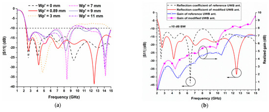
Figure 3.
Single element UWB antenna; (a) Study of patch dimension change of UWB antenna on the reflection coefficient and bandwidth; (b) Reflection coefficient and realized gain comparison of reference and modified UWB antenna.
A conventional UWB antenna is simulated, in Computer Simulation Technology (CST) software, as a reference antenna, resulting in an operation starting from 2.21 GHz to more than 15 GHz. Then, the modified UWB antenna is also simulated, producing an operating bandwidth from 2.327 GHz to more than 15 GHz. The reflection coefficient of a modified UWB antenna is enhanced to almost −15 dB throughout the operating band, whereas the reference UWB antenna reflection coefficient is close to −10 dB at around 8 GHz, as seen in Figure 3b. In addition to the reflection coefficient improvement seen, the gain of modified antenna is enhanced as well. The gain comparison of the conventional and modified UWB antennas is presented in Figure 3b. Throughout the operating frequency range, the modified UWB antenna has a higher gain. The gain of the modified UWB antenna is higher than 3 dBi from 3 GHz onwards compared to that of the conventional antenna. The gain of the modified UWB antenna continues to increase to 5.03 dBi at 10 GHz, and only 4.76 dBi gain is achieved by the reference UWB antenna at the same frequency.
2.2. Modified UWB Antenna Array
Next, the optimized modified single UWB antenna is applied to form a two-element UWB antenna array, as shown in Figure 4. The radiator of the conventional UWB antenna array is modified by cutting two adjacent sides to increase the spacing between the two patches and minimize mutual coupling. The final modified UWB antenna array consists of a two-element radiating patches with an inter-element spacing of d2 connected by an equal power divider. On the other hand, the reference UWB antenna array is designed similarly with this final antenna, with d1 representing its inter-element spacing. For the final modified UWB array, a rectangular section is removed from the center of the partial ground plane on its reverse side to improve matching. To further enhance the impedance matching throughout the UWB band, the shape of this partial ground plane modified to be in a trapezoidal shape. This shape is defined with an angle of ϕ between the substrate edge and the upper edge of the ground. All design parameters of the modified UWB antenna array are listed in Table 2.
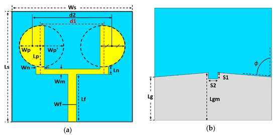
Figure 4.
Geometry of the modified UWB antenna array: (a) top view, (b) bottom view.
Table 2.
Design parameters of modified UWB antenna array.
The patch shape change (at different lengths of Wp′) of the UWB antenna array is first studied in terms of reflection coefficient and operating bandwidth. The influence of the change in the length of Wp′ on the reflection coefficient and impedance bandwidth is studied at Wp′ = 0–8.6 mm, as shown in Figure 5. Note that Wp′ = 0 mm corresponds to the half-patch of the radiated element and Wp′ = 8.6 mm corresponds to the full elliptical patch of the radiated element. At Wp′ = 0 mm (at d2 = 0.37 λL), the reflection coefficient response is higher than −10 dB around frequencies from 4.8 GHz to 6.3 GHz. This is due to the mismatch between the half-elliptical patch and the feeding line. When Wp′ = 1.75 mm (at d2 = 0.35 λL), the reflection coefficient response goes below −10 dB from 2.17 GHz to 10.052 GHz with a fractional bandwidth of 129%. When Wp′ > 1.75 mm (at d2 < 0.35 λL), the reflection coefficient response goes above −10 dB between 8 GHz and 9 GHz. Thus, optimum performance is obtained when the radiated patch has a P-shape (Wp′ = 1.75 mm and d2 = 0.35 λL). This is due to the increase of the inter-element spacing distance between elements, resulting in a significant reduction in the mutual coupling between the radiating elements.
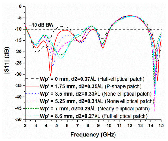
Figure 5.
Study of patch dimension change of a UWB antenna array on the reflection coefficient and bandwidth.
Figure 6 shows the reflection coefficient, impedance bandwidth, and realized gain of reference and modified UWB antenna array. The reference UWB antenna array operates from 2.502 GHz to 8.166 GHz, with an impedance bandwidth of 5.664 GHz. On the other hand, the modified UWB antenna array starts operating at 2.17 GHz and stops at 10.052 GHz, with an impedance bandwidth of 7.882 GHz. Comparison in terms of realized gain shows that the modified antenna array enhanced realized gains by at least 2 dBi and exceeds 3.5 dBi in some frequencies within the UWB operating band. These improvements in the modified UWB antenna array performance are due to the increased inter-element distance and reduction of mutual coupling between the radiating elements. The inter-element spacing distances are d2 = 0.35 λL and d1 = 0.27 λL respectively for the modified and reference antenna array. These enhancement enables the modified array to be easily integrated with the single-wing UWB bandpass filter and will be described in the next section.
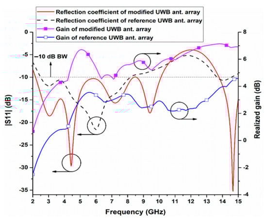
Figure 6.
Simulated reflection coefficients and realized gain of the reference and modified UWB antenna array.
3. Modified UWB Antenna Array with Multimode Resonator Filter
3.1. Multimode Resonator-Based UWB Bandpass Filter
In this study, a multimode resonator UWB bandpass filter based on the concept of a stepped-impedance resonator (SIR) is designed [39]. The single-wing UWB bandpass filter is chosen due to its wide impedance bandwidth, good transmission and reflection coefficients, size compactness, and ease of integration with UWB antennas. This bandpass filter is formed using two pairs of interdigital-coupled lines that are connected to 50 Ω terminals and a single-wing stub. These interdigital-coupled lines are equivalent to two pairs of transmission lines, whereas the single-wing stub is designed to perform impedance stepping, which creates multiple modes within the UWB band. Due to the strong coupling of the interdigital-coupled lines and the overlapping of high-frequency modes, a UWB bandpass response from 3.1 GHz to more than 10.6 GHz is achieved [40]. The interdigital-coupled lines are designed with a length of with respect to the upper frequency band. For narrowband antennas, the dimensions of the single-wing impedance transformer applied to the interdigital-coupled lines can be designed with reduced impedance matching bandwidth. The single-wing bandpass filter and its equivalent circuit are shown in Figure 7, whereas its design parameters are summarized in Table 3 (all units in mm). The fabricated single-wing bandpass filter is illustrated in Figure 8.
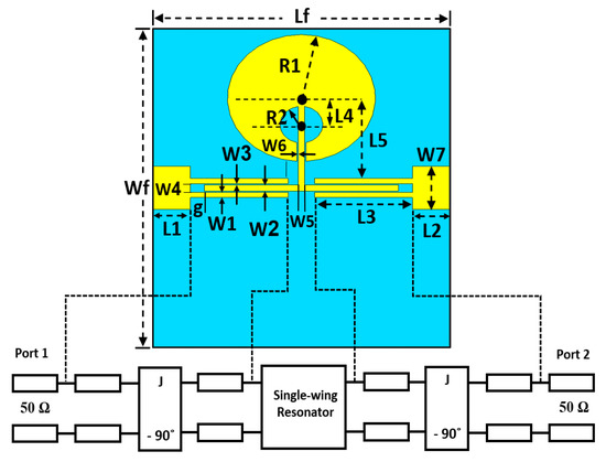
Figure 7.
Single-wing UWB multimode resonator (MMR) bandpass filter and its equivalent circuit.
Table 3.
Design parameters of the single-wing UWB MMR bandpass filter.
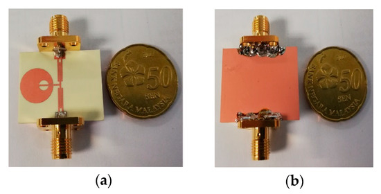
Figure 8.
Prototype of the UWB single-wing bandpass filter: (a) Front view, (b) Back view.
The multimode bandpass filter is measured using Vector Network Analyzer (VNA). The measured S-parameters (S11, S12, S21, S22) of the filter are compared with simulated results obtained from CST software as shown in Figure 9. The measured results indicate a –10 dB reflection coefficient (S11) from 2.77 GHz to 11.23 GHz, and about 1 dB of transmission coefficient (S21). A close agreement is observed between the simulation and measurement results. The offsets in frequency observed is due to substrate permittivity variation and fabrication resolution tolerance.
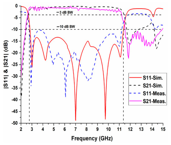
Figure 9.
S-Parameters of the fabricated UWB single-wing bandpass filter.
3.2. Integration of Modified UWB Antenna Array and BPF Filter
Upon the optimization of the modified UWB antenna array in terms of reflection coefficient, impedance bandwidth, and gain, it is now integrated with the single-wing MMR bandpass filter. As shown in Figure 10, the single-wing MMR bandpass filter is embedded in the feedline of the modified UWB antenna array that consists of two-element patches with the modified partial ground plane. Table 4 lists the designs parameters of the UWB antenna array with the bandpass filter in mm.
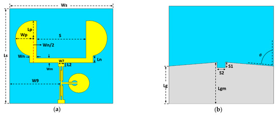
Figure 10.
Geometry of the integrated UWB antenna array with the single-wing bandpass filter: (a) Front view, (b) Back view.
Table 4.
Design parameters of the UWB filtering antenna array.
Reflection coefficients of modified UWB antenna array before and after integration with the single-wing BPF as well as the reference UWB antenna array are compared as in Figure 11. The reference UWB antenna array has a narrow impedance bandwidth from 2.8 GHz to 8 GHz, which does not cover the entire UWB band. This is due to the small inter-element spacing between antenna array elements that led to a strong mutual coupling and resulted in a poor reflection coefficient and impedance bandwidth. A UWB antenna array with a bandpass filter is observed to operate from 2.967 GHz to 10.05 GHz, with an equivalent fractional bandwidth of 108.83%. The integrated design can suppress the upper frequencies up to 15 GHz. In contrast, the reflection coefficient of UWB antennas without the bandpass filter operates from 2.17 GHz to 10.052 GHz, with a higher order mode generated at around 14.5 GHz. This indicates that the suppression capability of lower and upper bands is not achieved and may potentially cause interference with other wireless communication systems operating in these frequency bands.
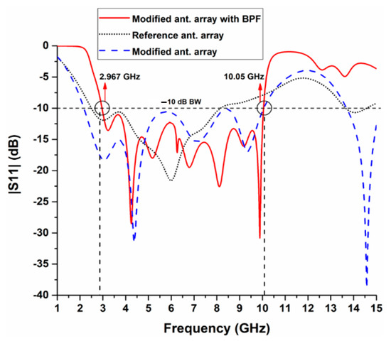
Figure 11.
Simulated reflection coefficients of reference antenna array, modified antenna array, and modified antenna array with bandpass filter (BPF).
The realized gain and radiation efficiency of the UWB antenna array with and without the single-wing bandpass filter are compared in Figure 12. From the low frequency of 3.1 GHz to around 6 GHz, the realized gain of the UWB antenna array is similar to that of the UWB antenna array integrated with the bandpass filter. However, at frequencies of more than 6 GHz, the gain of UWB antenna array with the bandpass filter increases to a maximum of 7.636 dBi at 10.35 GHz. After 10.35 GHz, the gain of this antenna array decreases to reach its minimum of lower than 4.28 dBi at 12 GHz. It is observed that the presence of the filter has suppressed high frequencies (higher than UWB band), which reduces the radiated power at these frequencies and thus eliminated their interference with other adjacent wireless devices. It is observed that the variation in terms of gain within the UWB band is more evident in the filtering antenna in comparison to that of the antenna array. This is associated with the variation in impedance matching at different frequencies within UWB band, besides the strong coupling between the interdigital lines of the MMR and the feedlines. From the radiation efficiency response of the UWB antenna array with and without a bandpass filter, it can be seen that the radiation efficiency of the UWB antenna array without a filter is around 96% throughout the simulated frequency range, whereas the UWB filtering antenna array radiation efficiency is around 95% in the selected UWB band and dropped significantly in the out-of-band frequencies. This drop in the out-of-band frequencies radiation efficiency is due to the single-wing bandpass filter, which suppressed the power of the unwanted frequencies from radiating.
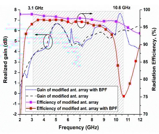
Figure 12.
Simulated realized gain and radiation efficiency of the modified UWB antenna array with and without BPF.
To investigate the operation of the single-wing bandpass filter on UWB antenna array, the current distribution densities are simulated at 10 GHz for both UWB antenna arrays. As seen in Figure 13a, a higher current distribution density is achieved with the presence of the bandpass filter in the array compared to the current distribution density of the array without filter, as illustrated in Figure 13b. This is due to the strong currents flow on the interdigital coupled lines in the single-wing bandpass filter, especially in the x direction. These currents are of the same phase with the modified radiated patch, resulting in a significant realized gain enhancement.
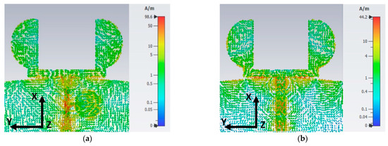
Figure 13.
Current distributions at 10 GHz for the UWB antenna array: (a) Antenna array with single-wing filter, (b) Antenna array without filter.
Then, all UWB antennas are fabricated using Roger RO4003C board, with a relative permittivity of 3.38, thickness of 1.524 mm, and a tangent loss of 0.0027. The prototypes of the single UWB antenna and UWB antenna array integrated with the filter are shown in Figure 14.
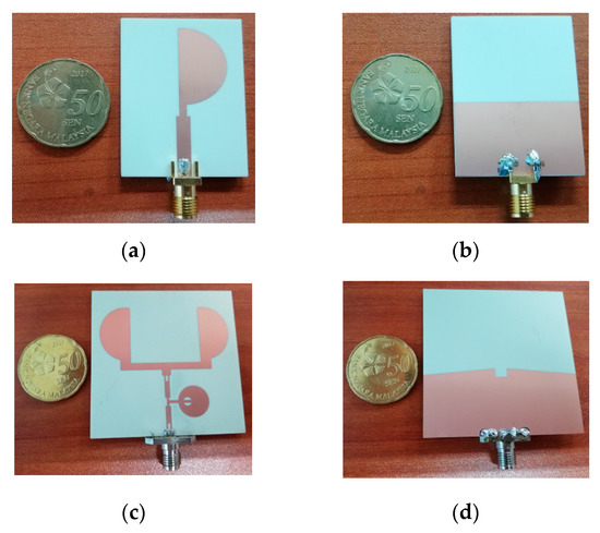
Figure 14.
Photograph of the UWB antenna prototypes: (a) Modified UWB antenna front view, (b) Modified UWB antenna back view, (c) Modified UWB filtering antenna array front view, (d) Modified UWB filtering antenna array back view.
Figure 15 reflects the simulation and measurement results of the reflection coefficients of the modified single UWB antenna and modified UWB antenna array with filtering function. The simulation results are obtained using CST software, whereas measurement results are obtained using Vector Network Analyzer (VNA). It is noted that the simulated and measured −10 dB reflection coefficient response of a single antenna covers a frequency range from less than 2.33 GHz up to 15 GHz. On the other hand, the reflection coefficient obtained from the simulation and measurement of the UWB filtering antenna array covers the UWB band and suppresses the lower and higher frequencies up to 15 GHz. This filtering capability is an advantage of integrating the UWB single-wing bandpass filter within the antenna array. The slight difference between simulation and measurement results of the reflection coefficient is due to the substrate permittivity variation and fabrication resolution tolerance.
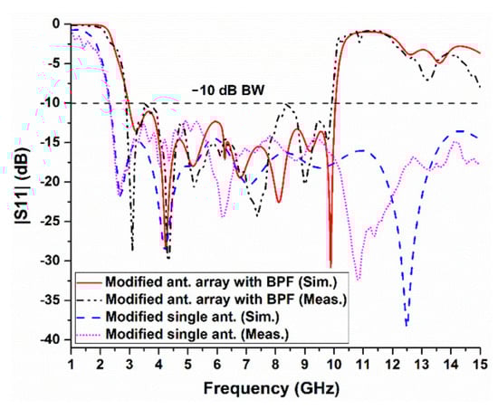
Figure 15.
Simulated and measured reflection coefficients of a single modified UWB antenna and UWB antenna array integrated with BPF.
The gains and radiation patterns measurement of the reported antenna array with a filtering function was conducted in an anechoic chamber in Universiti Teknologi MARA (UiTM) and the measurement was stepped up as shown in Figure 16. A horn antenna was set as a transmitter, and the fabricated prototype of the UWB filtering antenna array was put as a receiver. The distance between the transmitting horn antenna and antenna under test, R, is set to 1.5 m. For E-plane radiation measurement, the receiving antenna is rotated from 0° to 360° on its axis in steps of 5°. The measurement for the radiation pattern is repeated in another plane (H-plane) by rotating both transmitting and receiving antennas by 90°. The antenna gain is obtained by applying the Friis equation and the gain transfer method [41].
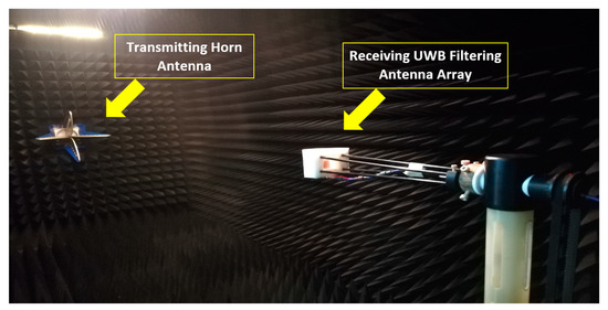
Figure 16.
Radiation and gain measurement setup of UWB filtering antenna array.
The simulated and measured realized gain results of the modified single UWB antenna and modified UWB filtering antenna array are compared as shown in Figure 17. It can be observed that the integrated filter within the antenna array has enhanced the gain around 10 GHz and reduced gain in the upper frequencies higher than 10.6 GHz by more than 3 dBi. This indicates the effectiveness of the proposed filter. The maximum achieved gain of the fabricated prototype is 7.4 dBi, whereas 7.64 dBi is obtained from simulation. This variation in gain is associated with the impedance matching variation at different frequencies within UWB band. This variation in the impedance is due to the strong coupling between the interdigital lines of MMR and the feed lines, besides small environmental effects during measurements.
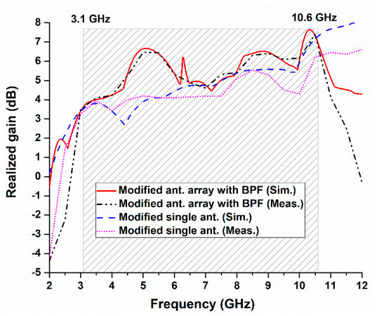
Figure 17.
Simulated and measured realized gain of single modified UWB antenna and UWB filtering antenna array.
The simulated and measured results of the radiation patterns of the modified UWB antenna array with a bandpass filter are compared at 3 GHz, 5 GHz, and 9 GHz, as presented in Figure 18. Close agreements are observed between simulation and measurement results. The reported antenna array has an omnidirectional radiation property in the H-plane, with similar radiation characteristics as that of the conventional UWB antenna array without filtering capability. This indicates that there is no degradation of radiation performance associated with the bandpass filter integration.
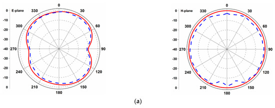
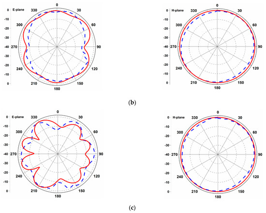
Figure 18.
Simulated (solid line) and measured (dashed line) radiation patterns of modified UWB filtering antenna array: (a) At 3 GHz, (b) At 5 GHz, and (c) At 9 GHz.
The features of the proposed filtering antenna are compared in detail in terms of design configuration, integrated filtering, center frequency, f0, size, profile, impedance bandwidth, IBW, fractional bandwidth, FBW, and peak gain with other literature in Table 5. It is evident that the proposed UWB antenna featured a wide operating bandwidth, high realized gain, and a compact size. These attractive features make the proposed design suitable for UWB applications.
Table 5.
Comparison of the proposed design with previous filtering antenna designs in literature.
4. Conclusions
In this article, a new design of UWB antenna array with the capability of filtering has been reported. The UWB antenna array is modified to obtain mutual coupling improvement, high realized gain, and wide impedance bandwidth while simultaneously maintaining the compact size. The integration of a UWB antenna array and multimode resonator bandpass filter eliminated its operation in the out-of-band frequencies (higher than 10.6 GHz). The realized gain at high frequencies is enhanced to more than 7.4 dBi, maintaining a compact size of 1.08 λ0 × 1.08 λ0 × 0.035 λ0 at a center frequency of 6.5 GHz. Furthermore, this UWB antenna array with an integrated filter achieves a wide fractional bandwidth of more than 109.87%. These features of the reported UWB antenna array with filtering capability make it a suitable choice for modern UWB wireless applications.
Author Contributions
Writing—original draft preparation, S.A.; methodology, S.A.; conceptualization, S.A.; software, S.A.; validation, S.A.; investigation, S.A.; resources, S.A. and T.K.G.; data curation, S.A., H.A. and F.H.; writing—review and editing, S.A., T.K.G., P.J.S., M.Y.A. and A.A.; formal analysis, S.A., F.H., H.A. and A.A.; visualization, S.A., F.H. and H.A.; project administration, T.K.G. and M.Y.A.; supervision, T.K.G. and M.Y.A. All authors have read and agreed to the published version of the manuscript.
Funding
This research work was supported by Multimedia University Graduate Research Assistant Scheme (MMU GRA) under Grant number: MMUI/170119.02.
Institutional Review Board Statement
Not applicable.
Informed Consent Statement
Not applicable.
Data Availability Statement
Not applicable.
Acknowledgments
The authors would like to thank Multimedia University (MMU) and Universiti Teknologi MARA (UiTM) for their assistance in measurement process. The authors thank the Siti-Hasmah digital library for providing reference resources.
Conflicts of Interest
The authors declare no conflict of interest.
References
- Federal Communications Commission. The Federal Communications Commission Revision of Part 15 of the Commission’s Rules Regarding Ultra-Wideband Transmission Systems From 3.1 to 10.6 GHz; Federal Communications Commission: Washington, DC, USA, 2002; pp. 98–153. [Google Scholar]
- Balderas, L.I.; Reyna, A.; Panduro, M.A.; Del Rio, C.; Gutierrez, A.R. Low-Profile Conformal UWB Antenna for UAV Applications. IEEE Access 2019, 7, 127486–127494. [Google Scholar] [CrossRef]
- Mahmud, M.Z.; Islam, M.T.; Misran, N.; Almutairi, A.F.; Cho, M. Ultra-Wideband (UWB) Antenna Sensor Based Microwave Breast Imaging: A Review. Sensors 2018, 18, 2951. [Google Scholar] [CrossRef] [PubMed]
- Slimani, A.; Bennani, S.D.; El Alami, A.; Amellal, M. Gain and Bandwidth Enhancement of New Planar Microstrip Array Antennas Geometry for C Band Weather Radar Applications. Int. J. Microw. Wirel. Technol. 2017, 9, 1139–1146. [Google Scholar] [CrossRef]
- Karoui, M.S.; Ghariani, N.; Lahiani, M.; Ghariani, H. A Compact UWB Elliptic Antenna for Indoor Localization System. IEICE Electron. Express 2019, 16, 1–5. [Google Scholar] [CrossRef]
- Yadav, A.; Singh, V.K.; Bhoi, A.K.; Marques, G.; Garcia-Zapirain, B.; de la Torre Díez, I. Wireless Body Area Networks: UWB Wearable Textile Antenna for Telemedicine and Mobile Health Systems. Micromachines 2020, 11, 558. [Google Scholar] [CrossRef] [PubMed]
- Saha, T.K.; Knaus, T.N.; Khosla, A.; Sekhar, P.K. A CPW-Fed Flexible UWB Antenna for IoT Applications. Microsyst. Technol. 2018, 1–7. [Google Scholar] [CrossRef]
- Rahman, M.U.; NagshvarianJahromi, M.; Mirjavadi, S.S.; Hamouda, A.M. Compact UWB band-notched antenna with integrated bluetooth for personal wireless communication and UWB applications. Electronics 2019, 8, 158. [Google Scholar] [CrossRef]
- Alhegazi, A.; Zakaria, Z.; Shairi, N.A.; Ibrahim, I.M.; Ahmed, S. A Novel Reconfigurable UWB Filtering-Antenna with Dual Sharp Band Notches Using Double Split Ring Resonators. Prog. Electromagn. Res. C 2017, 79, 185–198. [Google Scholar] [CrossRef]
- Chen, S.; Zhao, Y.; Peng, M.; Wang, Y. A Codesigned Compact Dual-Band Filtering Antenna with PIN Loaded for WLAN Applications. Int. J. Antennas Propag. 2014, 2014, 826171. [Google Scholar] [CrossRef]
- Jadhav, J.B.; Deore, P.J. Filtering Antenna with Radiation and Filtering Functions for Wireless Applications. J. Electr. Syst. Inf. Technol. 2016, 4, 125–134. [Google Scholar] [CrossRef]
- Tang, H.; Chen, J.X.; Chu, H.; Zhang, G.Q.; Yang, Y.J.; Bao, Z.H. Integration Design of Filtering Antenna with Load-Insensitive Multilayer Balun Filter. IEEE Trans. Compon. Packag. Manuf. Technol. 2016, 6, 1408–1416. [Google Scholar] [CrossRef]
- Cui, J.; Zhang, A.; Yan, S. Co-Design of a Filtering Antenna Based on Multilayer Structure. Int. J. RF Microw. Comput. Eng. 2019, 30, 22096. [Google Scholar] [CrossRef]
- Jiang, Z.H.; Werner, D.H. A Compact, Wideband Circularly Polarized Co-designed Filtering Antenna and Its Application for Wearable Devices with Low SAR. IEEE Trans. Antennas Propag. 2015, 63, 3808–3818. [Google Scholar] [CrossRef]
- Yang, W.; Chen, S.; Xue, Q.; Che, W.; Shen, G.; Feng, W. Novel Filtering Method Based on Metasurface Antenna and Its Application for Wideband High-Gain Filtering Antenna With Low Profile. IEEE Trans. Antennas Propag. 2019, 67, 1535–1544. [Google Scholar] [CrossRef]
- Jiang, Z.H.; Gregory, M.D.; Werner, D.H. Design and Experimental Investigation of a Compact Circularly Polarized Integrated Filtering Antenna for Wearable Biotelemetric Devices. IEEE Trans. Biomed. Circuits Syst. 2016, 10, 328–338. [Google Scholar] [CrossRef] [PubMed]
- Sahu, B.; Singh, S.; Meshram, M.K.; Singh, S.P. Integrated Design of Filtering Antenna with High Selectivity and Improved Performance for L-Band Applications. AEU Int. J. Electron. Commun. 2018, 97, 185–194. [Google Scholar] [CrossRef]
- Cheng, W. Compact 2.4-GHz Filtering Monopole Antenna Based on Modified SRR-Inspired High-Frequency-Selective Filter. Optik 2016, 127, 10653–10658. [Google Scholar] [CrossRef]
- Tang, M.C.; Chen, Y.; Ziolkowski, R.W. Experimentally Validated, Planar, Wideband, Electrically Small, Monopole Filtennas Based on Capacitively Loaded Loop Resonators. IEEE Trans. Antennas Propag. 2016, 64, 3353–3360. [Google Scholar] [CrossRef]
- Zhou, H.; Qu, S.; Lin, B.; Wang, J.; Ma, H.; Xu, Z.; Peng, W.; Bai, P. Filter-Antenna Consisting of Conical FSS Radome and Monopole Antenna. IEEE Trans. Antennas Propag. 2012, 60, 3040–3045. [Google Scholar] [CrossRef]
- Yang, S.J.; Cao, Y.F.; Pan, Y.M.; Wu, Y.; Hu, H. Balun-Fed Dual-Polarized Broadband Filtering Antenna Without Extra Filtering Structure. IEEE Antenna Wirel. Propag. Lett. 2020, 19, 656–660. [Google Scholar] [CrossRef]
- Yang, H.; Xi, X.; Zhao, Y.; Wang, L.; Shi, X. Design of Compact Ultrawideband Slot Antenna With Improved Band-Edge Selectivity. IEEE Antennas Wirel. Propag. Lett. 2018, 17, 946–950. [Google Scholar] [CrossRef]
- Tang, M.C.; Shi, T.; Ziolkowski, R.W. Planar Ultrawideband Antennas with Improved Realized Gain Performance. IEEE Trans. Antennas Propag. 2016, 64, 61–69. [Google Scholar] [CrossRef]
- Sahu, B.; Singh, S.; Meshram, M.K.; Singh, S.P. A New Compact Ultra-Wideband Filtering Antenna with Improved Performance. J. Electromagn. Waves Appl. 2018, 33, 107–124. [Google Scholar] [CrossRef]
- Sahoo, A.K.; Gupta, R.D.; Parihar, M.S. Highly selective integrated filter antenna for UWB application. Microw. Opt. Technol. Lett. 2017, 59, 1032–1037. [Google Scholar] [CrossRef]
- Sonkki, M.; Pfeil, D.; Hovinen, V.; Dandekar, K.R. Wideband Planar Four-Element Linear Antenna Array. IEEE Antennas Wirel. Propag. Lett. 2014, 13, 1663–1666. [Google Scholar] [CrossRef]
- Kim, S.; Nam, S. A Compact and Wideband Linear Array Antenna with Low Mutual Coupling. IEEE Trans. Antennas Propag. 2019, 67, 5695–5699. [Google Scholar] [CrossRef]
- Kasi, B.; Chakrabarty, C.K. Ultra-Wideband Antenna Array Design for Target Detection. Prog. Electromagn. Res. C 2012, 25, 67–79. [Google Scholar] [CrossRef]
- Slimani, A.; Bennani, S.D.; El Alami, A.; Terhzaz, J. Ultra Wideband Planar Microstrip Array Antennas for C-Band Aircraft Weather Radar Applications. Int. J. Antennas Propag. 2017, 2017, 2346068. [Google Scholar] [CrossRef]
- Xue, J.X.; Xie, Z.M. A Filtering Antenna Array Based on Multimode Resonator. In Proceedings of the 2017 Sixth Asia-Pacific Conference on Antennas and Propagation (APCAP), Xi’an, China, 16–19 October 2017; pp. 1–3. [Google Scholar]
- Zhang, C.X.; Zhuang, Y.Q.; Zhang, X.K.; Hu, L.Z. An UWB Microstrip Antenna Array with Novel Corporate-Fed Structure. Prog. Electromagn. Res. C 2014, 52, 7–12. [Google Scholar] [CrossRef]
- Zhang, Y.; Zhang, X.Y.; Pan, Y.M. Compact Single- and Dual-Band Filtering Patch Antenna Arrays Using Novel Feeding Scheme. IEEE Trans. Antennas Propag. 2017, 65, 4057–4066. [Google Scholar] [CrossRef]
- Li, Y.; Zhao, Z.; Tang, Z.; Yin, Y. Differentially-Fed, Wideband Dual-Polarized Filtering Antenna With Novel Feeding Structure for 5G Sub-6 GHz Base Station Applications. IEEE Access 2019, 7, 184718–184725. [Google Scholar] [CrossRef]
- Hua, C.; Li, R.; Wang, Y.; Lu, Y. Dual-Polarized Filtering Antenna With Printed Jerusalem-Cross Radiator. IEEE Access 2018, 6, 9000–9005. [Google Scholar] [CrossRef]
- Lin, C.K.; Chung, S.J. A Filtering Microstrip Antenna Array. IEEE Trans. Microw. Theory Tech. 2011, 59, 2856–2863. [Google Scholar] [CrossRef]
- Ray, K.P. Design Aspects of Printed Monopole Antennas for Ultra-Wide Band Applications. Int. J. Antennas Propag. 2008, 2008, 713858. [Google Scholar] [CrossRef]
- Adam, A.A.; Rahim, S.K.A.; Tan, K.G.; Reza, A.W. Design of 3.1–12 GHz Printed Elliptical Disc Monopole Antenna with Half Circular Modified Ground Plane for UWB Application. Wirel. Pers. Commun. 2012, 69, 535–549. [Google Scholar] [CrossRef]
- Srifi, M.N.; Podilchak, S.K.; Essaaidi, M.; Antar, Y.M.M. Compact Disc Monopole Antennas for Current and Future Ultrawideband (UWB) Applications. IEEE Trans. Antennas Propag. 2011, 59, 4470–4480. [Google Scholar] [CrossRef]
- Li, R.; Zhu, L. Compact UWB Bandpass Filter Using Stub-Loaded Multiple-Mode Resonator. IEEE Microw. Wirel. Compon. Lett. 2007, 17, 40–42. [Google Scholar] [CrossRef]
- Xia, X.; Chen, F.; Cheng, X.; Deng, X. A Compact Ultra-Wideband Bandpass Filter with Good Selectivity Based on Interdigital Coupled-Line. Int. J. RF Microw. Comput. Eng. 2018, 28, 21419. [Google Scholar] [CrossRef]
- Stutzman, W.L.; Gary, A. Thiele, Antenna Theory and Design; John Wiley Sons: Hoboken, NJ, USA, 2012; pp. 100–125. [Google Scholar]


Publisher’s Note: MDPI stays neutral with regard to jurisdictional claims in published maps and institutional affiliations. |
© 2021 by the authors. Licensee MDPI, Basel, Switzerland. This article is an open access article distributed under the terms and conditions of the Creative Commons Attribution (CC BY) license (http://creativecommons.org/licenses/by/4.0/).