Abstract
The paper presents time, frequency, and real-time properties of a fractional-order PID controller (FOPID) implemented at a STM 32 platform. The implementation uses CFE approximation and discrete version of a Grünwald–Letnikov operator (FOBD). For these implementations, experimental step responses and Bode frequency responses were measured. Real-time properties of the approximations are also examined and analyzed. Results of tests show that the use of CFE approximation allows to better keep the soft real-time requirements with an accuracy level a bit worse than when using the FOBD. The presented results can be employed in construction-embedded fractional control systems implemented at platforms with limited resources.
1. Introduction
The FOPID control is one of the main areas of application of fractional calculus in automatic control. The book [1] describes the issue of fractional-order systems very well, from theory to practice. The next step in utilizing this control is hardware implementation. Therefore, many implementations have been presented, including the Microcontroller, Field Programmable Gate Array, Field Programmable Analog Array, and Switched Capacitor. A good extension is the book [2] presenting further applications, including, for example, electrochemistry.
It is known that fractional calculus is not a new idea. It has been analysed by mathematicians since the XVII century, but later it was forgotten due to difficulties in its application in solving real problems in physics and engineering. Fractional calculus is also the main topic of the fundamental book [3]. Its theoretical introduction contains information about both classical and fractional-order discrete calculus. In the following parts of the book, a lot of emphasis is placed on digital image processing. The book [4] also describes many uses of fractional-order control, such as coupled tank systems or MAGLEV.
Several studies have compared FOPID and PID using different quality indicators. In the article [5], a comparison of both controllers was done for selected MIMO systems with a delay. In [6], the same comparison was made, but in the hardware implementation (Arduino Uno) using the Nelder-Mead method for both optimizations. The authors indicated a much faster settling and rise time for the FOPID controller than its classical counterpart.
One of the microcontroller implementations of FOPID is described in [7]. The controller was used for speed control of the buck converter-fed DC motor. The authors noted that FOPID performed better than standard PID. It was also indicated that the control energy required to control the speed of the DC motor was less than in the typical PID implementation. The article [8] describes the use of fractional-order for feedback control of the DC motor speed. The hardware realization was proposed in digital form with the microprocessor based on Bode’s ideal control loop.
Tuning of FOPID still causes some difficulties. In the article [9], the authors formulated the optimization problem with three objective functions, including the integral of absolute error (IAE), absolute steady-state error, and settling time. Many methods were compared, including: multi-objective extremal optimization (MOEO), genetic algorithm (GA), particle swarm optimization (PSO), and chaotic antiswarm (CAS). Another article that deals with tuning is [10]. The authors decided to use two methods for systems with discrete time. The controller was tested on three simulation examples and one experiment using a DC motor and PWM control.
Microcontroller implementations of FOPID have not been thoroughly analyzed from real-time requirements’ and frequency properties’ point of view. The paper [11] presents analysis of real-time properties of FO elements implemented at PLC. Article [12] is another example of a real-time implementation of FOPID. The authors focused on examining control performance, disturbance rejection properties, and the trajectory tracking ability of the system. The frequency properties are presented in the article [13]. It compares Oustaloup, refined Oustaloup, and Matsuda approximations. Additionally, the authors focused on time domain and stability analysis.
There are many examples of the use of the hard real-time FO control system. One of the m is given in article [12]. It presents LabView implementation of the controller for the magnetic levitation (MAGLEV) system. Other examples of the use of FOPID in MAGLEV are presented in [14,15]. The FOPID controller was also used in [16] for the full control of quadrotors (attitude and position).
The digital implementation of the fractional order requires application of its discrete, finite-dimensional approximations. The most typical are: fractional-order Backward Difference (FOBD) approximation (directly derived from the Grünwald-Letnikov definition) and CFE approximation. The accuracy of CFE is a little bit worse than PSE, but its numerical complexity is significantly smaller due to relatively the low order of the discrete transfer function describing it. Both methods are analyzed in this paper. The accuracy of FOPID implementation using both methods is deeply analysed in the paper [17].
This paper presents the analysis of real-time and frequency properties of the FOPID controller implemented at the typical microcontroller platform. The FOPID is implemented with the use of the most typical discrete approximations: FOBD and CFE. For these implementation step responses, Bode diagrams and basic real-time properties are estimated and compared. Such an analysis has not been presented yet.
The paper is organized as follows: at the beginning, elementary ideas and definitions are recalled. The CFE approximation, the discrete GL operator, and analytical formulae of step and frequency responses are presented too. Afterwards, the experimental platform and tests are presented and discussed.
2. Preliminaries
2.1. Elementary Ideas of Fractional Calculus
Elementary ideas from fractional calculus can be found in many books, such as [2,3,18,19]. Here, only the most elementary definitions are provided.
Firstly, the fractional-order, integro-differential operator is given (e.g., [2,19,20]):
Definition 1.
(The elementary fractional-order operator) The fractional-order integro-differential operator is defined as follows:
where a and t denote time limits for operator calculation, and denotes the non-integer order of the operation.
After that, please see an idea of the Gamma Euler function ([20]):
Definition 2.
The Gamma function
Furthermore, the Mittag–Leffler function is presented. It is a non-integer order generalization of exponential function . It plays a crucial rule in the solution of the FO state equation. It is defined as below:
Definition 3.
The one parameter Mittag-Leffler function
The fractional-order, integro-differential operator (1) is described with different definitions, given by Grünwald and Letnikov (GL definition), Riemann and Liouville (RL definition), and Caputo (C definition). Relations between these operators are given, for example, in [2] or [21]. Discrete versions of these operators are analysed in detail in [22]. In the further consideration, only the GL definition is applied and needs to be presented. It has as follows ([1,23]):
Definition 4.
(The Grünwald-Letnikov definition of FO operator)
In (4) is the fractional-order, h is the sample time, is the nearest integer value, and is the binomial coefficient:
Next, the basic formula of the fractional-order PID (FOPID) controller should be remembered. It can be expressed by the following transfer function (e.g., [17]):
where and denote non-integer orders of integral and derivative actions, and are coefficients of proportional, integral, and derivative actions respectively.
The step response of the FOPID (6) is as follows (see [17]):
where is the complete Gamma function. The formula (7) will be used as a reference to testing the accuracy of step responses for both approximations.
The frequency response can be calculated using transfer function (6) replacing . It is as follows:
where:
and the module and phase are as follows:
If the half-order controller is considered, that is , the relation (9) takes the following form:
and consequently, (10) turns to:
Analytical expressions (12) describing module and phase will be applied to verify the experimental Bode diagrams in Section 4.
The digital implementation of the controller (6) requires use of discrete, finite dimensional approximation of both elements and . This can be done using two typical methods. The fist one directly uses a GL definition and has a form of the FIR filter containing only zeros. An alternative approach uses the IIR filter containing both zeros and poles. Both methods will be presented and tested in this paper.
2.2. The Fractional-Order Backward Difference (FOBD)
The FOBD is directly associated to the GL definition, because the GL definition is a limit case of FOBD for (see, e.g., [3], p. 68).
Definition 5.
(The fractional-order Backward Difference-FOBD)
Denote coefficients by :
The coefficients (14) can also be calculated with the use of the following equivalent recursive formula (see, e.g., [1], p. 12), which is very useful in numerical calculations:
In paper [24] it is proven that:
Equations (15) and (16) yield:
The FOBD approximation described by (13) with coefficients computed using formula (15) will be used in microcontroller implementation presented in the next section. Its length L should be relatively long to obtain good accuracy.
2.3. The CFE Approximation
The CFE approximator is an alternative way to express the basic fractional element . It has the form of an IIR filter containing both poles and zeros. It is a faster convergent and easier to implement because its order is relatively low, typically not higher than 5. CFE is obtained via discretization of a basic element . This can be done using a so-called generating function . The new operator raised to the power has the following form (see [8,25]):
where M is the order of approximation, and is the coefficient depending on sample time and type of approximation:
In Equation (19) h is the sample time and a is the coefficient depending on approximation type. For and , we obtain the Euler and Tustin approximations, respectively. For we arrive at the Al-Alaoui-based approximation, which is a linear combination of the Euler and Tustin approaches. Note that in this case, the parameter a in Equation (18) equals to , with being the Al-Alaoui weighting coefficient [26,27]. Numerical values of coefficients and and various values of the parameter a can be calculated with the use of the MATLAB function written by I. Petras are available at [28]. If the Tustin approximation is considered (a = 1), then and the polynomial can be given in the direct form (see [25]). Examples of the polynomial for are given in the Table 1, and an example of the polynomial for and (Euler approximation) is given in the Table 2. The detailed analysis of various forms of CFE approximators has been presented by [27].

Table 1.
Coefficients of CFE polynomials for Tustin approximation.

Table 2.
Coefficients of CFE polynomials for Euler approximation.
3. The Experimental Microcontroller Platform
The diagram of the embedded system used in experiments is shown in Figure 1. The STM32F767ZI device is based on the high-performance Arm® Cortex®-M7 32-bit RISC core operating at up to 216 MHz frequency. The Cortex®-M7 core features a floating point unit (FPU) which supports Arm® double-precision and single-precision data-processing instructions and data types. It also implements a full set of DSP instructions. The embedded system was tested using the following peripheral blocks integrated in the structure: SRAM memory for storing data tables, timer/counter units capable of interrupts, and a serial port UART. The processed data are duly transmitted (via an UART port), monitored, and uploaded to a PC. The FOPD and CFE algorithms were run in the timer interrupt procedure of the STM32 timer.
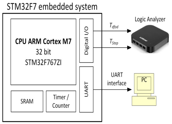
Figure 1.
The experimental system.
The Logic Analyzer of the Logic Pro 16 (Saleae Corp.) was used to monitor and collect digital information from digital I/Os of the embedded system. Two digital outputs pin of the STM32F767ZI processor were used to measure the time duration of the approximation of the digital fractional-order differentiator/integrator and one step-time duration of the differentiator/integrator unit step response . The accuracy of time measurement is 20 ns (50 MSample/s). All data were saved as specific log files to be analyzed off-line.
In the target application, the CPU clock frequency of the STM processor was set to 216 kHz. The UART port’s baud rate was bits/s. Response data of integral and derivative terms, the total response of the FOPID controller, and input signal were logged on the computer. Including the transmission frame header, 10 bytes were transmitted, which took about ms.
The approximation coefficients of the derivative and integrating parts of the FOPID controller were determined once during the initialization procedure of the processor. The variables of the double type were used to represent all application parameters. In fact, two functions were created to calculate CFE and FOBD parameters:
- doubledfodCFE( uint8_tn, doubleT, doublea, doubler, double*CFE_Num, double*CFE_Den );
- voiddfodPSE( uint16_tL, doubleT, doubler, double*PSE_Coeffs );
where n is an order of truncation equal to: 1, 2, 3, 4, or 5; T is a sampling period in [s]; a is a weighting factor between the range 0 <= a <= 1 (e.g.,: 0-Euler rule, 1-Tustin rule); r is an approximated fractional-order (); CFE_Num-transmittance numerator coefficients of CFE approximation; CFE_Den-transmittance denominator coefficients of CFE approximation; L is an order of truncation ( is recommended) and PSE_Coeffs – FOPD approximation coefficients.
FOPID inputs were generated in the timer interrupt handler. In the same procedure, the time response of the controller to input step and sine was calculated. The numerical procedure used to calculate both versions of the FOPID controller (CFE, FOBD), besides the standard arithmetic operators, requires shift and iterative operations. In the first case, the memcpy function of the c language was used, while in the second, the for. An example code used to calculate the FOBD output is as follows:
// **************************************************************************
for( uint16_t j=0; j <= L_PSE; j++)
{
y_PSE_Der[L_PSE] = y_PSE_Der[L_PSE] + PSE_Coeff_Der[j]*u_PSE[L_PSE-j];
y_PSE_Int[L_PSE] = y_PSE_Int[L_PSE] + PSE_Coeff_Int[j]*u_PSE[L_PSE-j];
}
// Calculation of the derivative, integral, and FOBD outputs.
Yout_Der = Td*( 1.0/pow(T,FracOrder_Der) )*y_PSE_Der[L_PSE]; // Derivative
Yout_Int = Ti*( 1.0/pow(T,FracOrder_Int) )*y_PSE_Int[L_PSE]; // Integral
Y_PID = Kp*u_PSE[L_PSE] + Yout_Int + Yout_Der; // FOBD
// Shifting the vectors of outputs and control:
memcpy( y_PSE_Der, y_PSE_Der+1, L_PSE*sizeof(double));
memcpy( y_PSE_Int, y_PSE_Int+1, L_PSE*sizeof(double));
memcpy( u_PSE, u_PSE+1, L_PSE*sizeof(double));
// Set the last element of derivative and integral vectors to 0:
y_PSE_Der[L_PSE] = 0;
y_PSE_Int[L_PSE] = 0;
// **************************************************************************
Step responses of the CFE and FOBD controller versions were determined for the same sampling frequency equal to 1 kHz.
Bode diagrams and histograms were carried out for different sampling rates, due to the different computation times of the CFE and FOBD algorithms and the additional time overhead resulting from the need to transmit data via the UART interface. Hence, a frequency of 2 kHz was selected for CFE and 1kHz for FOBD. These frequencies were the base frequencies for the sine wave generation. The sine period was built from 50 samples; therefore, for the base frequencies, a maximum of Hz and Hz were obtained for CFE and FOBD, respectively.
4. Experiments
Experiments were performed using the system presented in the previous section. During experiments, typical control signals were employed: step function and sine wave. The step response fully describes the time properties of a controller, and the sine function allows to test the frequency properties of a controller. These testing signals were program-generated.
Parameters of the tested FOPID are given in the Table 3. These parameters were divided into three sets according to the and fractional values.

Table 3.
Parameters of FOPID controller.
The quality of approximation was examined using known and cost functions:
where h is the sample time, and and are approximated and analytical responses, respectively. Analytical response was computed using (7).
4.1. Tests of FOBD
Firstly, the FOBD was tested. The memory length during calculations was equal . Bode diagrams were tested using a sine wave with a frequency range of 0.44–20.0 Hz. They are shown in the Figure 2. The comparison experimental vs. analytical Bode diagrams is illustrated by Figure 3. The analytical Bode diagrams were calculated for half-order FOPID using (12).
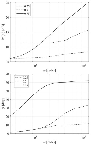
Figure 2.
The Bode diagrams of the magnitude and phase of FOPID using FOBD.
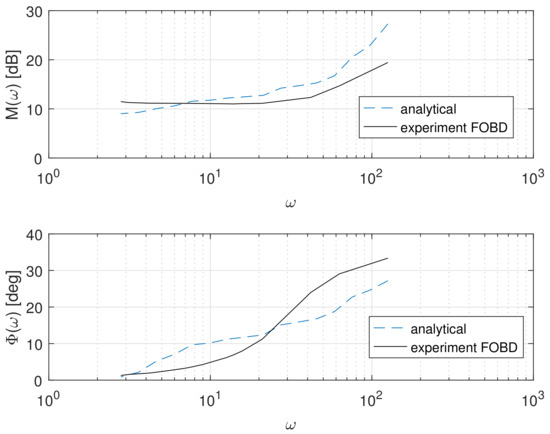
Figure 3.
Comparison analytical Bode diagrams to experiments using FOBD. .
The analytical and experimental step responses using FOBD are given in the Figure 4, Figure 5 and Figure 6. The analytical step responses were computed using (7).
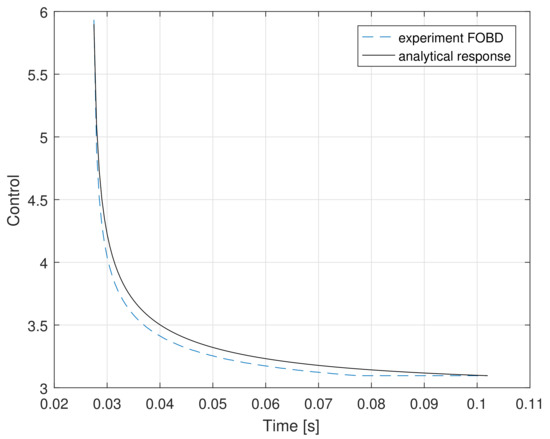
Figure 4.
The step-response of FOPID using FOBD vs. the analytical response for , . , and .
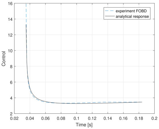
Figure 5.
The step-response of FOPID using FOBD vs. the analytical response for , . , and .
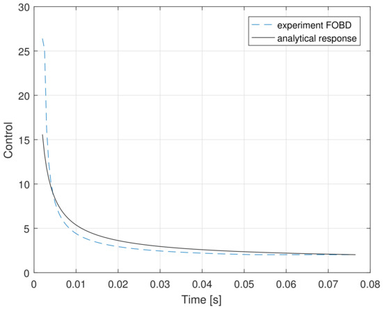
Figure 6.
The step-response of FOPID using FOBD vs. the analytical response for , . , and .
Appropriate histograms were determined in order to check the sampling period stability and calculate the PID algorithm execution time. The duration of calculations is presented in histograms Figure 7. The histograms were collected using a logic analyser, and the accuracy of time measurements was equal to 20 [ns]. The histogram on the left shows the keeping of sample time during calculations, and on the right it illustrates the duration of calculation of the control signal by a FOBD algorithm.
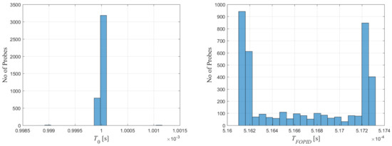
Figure 7.
Duration of calculations using FOBD.
4.2. Tests of CFE
The CFE approximation was examined analogously. The Bode diagrams were tested using a sine wave with frequencies from range: 0.88–40.0 Hz. Parameters of the CFE approximation for are given in the Table 4.

Table 4.
Parameters of CFE approximation.
The Bode diagrams for the FOPID approximated with the use of CFE are given in the Figure 8, while a comparison of analytical to experimental Bode diagrams is shown in Figure 9. The analytical Bode diagrams were obtained using (12).
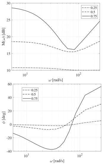
Figure 8.
The Bode diagrams of magnitude and phase of FOPID using CFE.
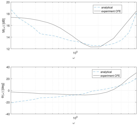
Figure 9.
Comparison analytical Bode diagrams to experimental using CFE. .
The comparison of step responses using CFE approximation vs. analytical responses are given in Figure 10, Figure 11 and Figure 12. The analytical response was calculated using the (7).
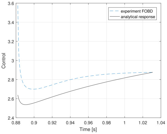
Figure 10.
The step response of FOPID using CFE vs. the analytical response, , . , and .
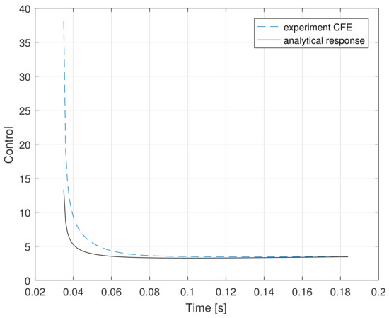
Figure 11.
The step-response of FOPID using CFE vs. the analytical response, , . , and .
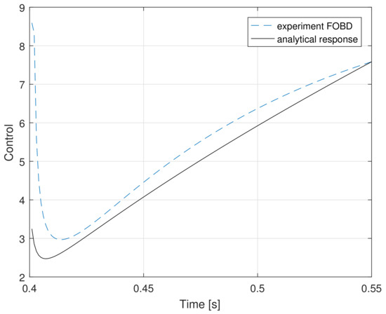
Figure 12.
The step-response of FOPID using CFE vs. the analytical response, , . , and .
The duration of calculations is illustrated by histograms Figure 13. Analogous to the above, the histogram on the left shows the keeping of sample time during calculations, and the right side illustrates the duration of calculation of the control signal by CFE algorithm.
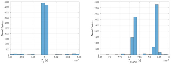
Figure 13.
Duration of calculations using CFE.
4.3. Discussion of Results
Differences between Bode diagrams Figure 2 and Figure 8 need to be explained first. The differences are caused by the different ranges of frequency during tests and different forms of discrete transfer functions expressing them. However, both approximations assure the general course of Bode diagrams close to the analytical one. This is shown by Figure 3 and Figure 9.
Next, the step responses given in Figure 4, Figure 5 and Figure 6 and Figure 10, Figure 11 and Figure 12 were analyzed. The cost functions (20) and (21) for both approximations and all considered fractional-orders and have been collected in Table 5 and Table 6.

Table 5.
Cost function IAE (20) for both approximations and all considered orders.

Table 6.
Cost function ISE (21) for both approximations and all considered orders.
The analysis of Table 5 and Table 6 shows that the FOBD is more accurate than CFE for all tested orders and . However, these differences are so small that using FOBD does not always make sense, especially as it is associated with a longer calculation time.
Parameters and for both implementations, responsible for real-time behaviour, are collected in the Table 7.

Table 7.
Comparison of real-time parameters for both methods. denotes the duration of control signal computing, and is the assumed sample time.
- The time for the implementation using FOBD is circa 100 times longer than using CFE.
- The standard deviation of the time is also smaller for CFE approximation.
- The standard deviation of assumed sample time is smaller for FOBD than for CFE.
Summarizing, the use of CFE allows to obtain a much smaller load of CPU during calculations, but the use of FOBD allows to better keep the assumed sample time, although calculations are longer. The accuracy of the time response is also better when using FOBD, than CFE.
5. Final Conclusions
The final conclusions from this paper are as follows:
- The FOPID controller using FOBD and CFE approximations can be implemented at a STM-32 platform with respect to soft real-time requirements.
- Both implementations are accurate in the sense of IAE and ISE cost functions.
- The comparison between analytical and experimental Bode diagrams confirms that frequency properties are modeled correctly by both approximations.
- The computation of the control signal using FOBD is much longer than the analogical using CFE, but FOBD assures better-keeping of the predefined sample time and a little bit better accuracy. This allows us to recommend the use of CFE approximation at digital platforms with bounded resources analogically, as for PLC systems (see [11]).
- Further investigations will cover preparing hard real-time implementations employed to control speedy real plants (e.g., the inverted pendulum or MAGLEV system).
Author Contributions
K.O.: Conceptualization, formal analysis, writing-original draft presentation, review and editing, supervision; M.R.: methodology, software, validation, writing-original draft presentation, review and editing, data analysis; J.Ż.-W.: state of the art recognition, data analysis, writing-original draft presentation, review and editing, visualization. All authors have read and agreed to the published version of the manuscript.
Funding
This research received no external funding.
Acknowledgments
This paper was sponsored by AGH UST project no 16.16.120.773.
Conflicts of Interest
The authors declare no conflict of interest.
Abbreviations
The following abbreviations are used in this manuscript:
| GL | Grünwald-Letnikov |
| FOBD | fractional-order Backward Difference |
| IO | Integer Order |
| FO | fractional-order |
| CFE | Continuous Fraction Expansion |
| IIR | Infinite Impulse Response |
| FIR | Finite Impulse Response |
| PSE | Power Series Expansion |
| MAGLEV | Magnetic Levitation System |
References
- Caponetto, R.; Dongola, G.; Fortuna, L.; Petras, I. Fractional-order systems: Modeling and control applications. In World Scientific Series on Nonlinear Science; Chua, L.O., Ed.; University of California: Berkeley, CA, USA, 2010; pp. 1–178. [Google Scholar]
- Das, S. Functional Fractional Calculus for System Identification and Controls; Springer: Berlin/Heidelberg, Germany, 2010. [Google Scholar]
- Ostalczyk, P. Discrete Fractional Calculus. Applications in Control and Image Processing; World Scientific: Singapore, 2016. [Google Scholar]
- Tepljakov, A. Applications of Fractional-Order Control: Fractional-Order Modeling and Control of Dynamic Systems; Springer: Berlin/Heidelberg, Germany, 2017; pp. 131–167. [Google Scholar]
- Kapoor, S.; Chaturvedi, M.; Juneja, P.K. Comparative Analysis of FOPID and Classical Controller Performance for an Industrial MIMO Process. Adv. Comput. Intell. Commun. Technol. Adv. Intell. Syst. Comput. 2020, 1086, 421–431. [Google Scholar]
- Masngut, I.; Pratama, G.N.P.; Cahyadi, A.I.; Herdjunanto, S.; Pakpahan, J.F.J. Design of fractional-order proportional-integral-derivative controller: Hardware realization. In Proceedings of the 2018 International Conference on Information and Communications Technology (ICOIACT), Yogyakarta, Indonesia, 6–7 March 2018; pp. 656–660. [Google Scholar]
- Khubalkar, S.; Chopade, A.; Junghare, A.; Aware, M.; Das, S. Design and Realization of Stand-Alone Digital fractional-order PID Controller for Buck Converter Fed DC Motor. Circuits Syst. Signal Process. 2016, 35, 2189–2211. [Google Scholar] [CrossRef]
- Petras, I. Fractional-order feedback control of a DC motor. J. Electr. Eng. 2009, 60, 117–128. [Google Scholar]
- Zeng, G.Q.; Chen, J.; Dai, Y.X.; Li, L.M.; Zheng, C.W.; Chen, M.R. Design of fractional-order PID controller for automatic regulator voltage system based on multi-objective extremal optimization. Neurocomputing 2015, 160, 173–184. [Google Scholar] [CrossRef]
- Merrikh-Bayat, F.; Mirebrahimi, N.; Khalili, M.R. Discrete-time fractional-order PID controller: Definition, tuning, digital realization and some applications. Int. J. Control. Autom. Syst. 2015, 13, 81–90. [Google Scholar] [CrossRef]
- Oprzędkiewicz, K.; Gawin, E.; Gawin, T. Real-time PLC implementations of fractional-order operator. In Proceedings of the Automation 2018: Advances in Automation, Robotics and Measurement Techniques, Warsaw, Poland, 15–17 March 2018; pp. 36–51. [Google Scholar]
- Midhun, E.; Sunil Kumar, T. LabVIEW based real-time implementation of fractional-order PID controller for a magnetic levitation system. In Proceedings of the 2016 IEEE 1st International Conference on Power Electronics, Intelligent Control and Energy Systems (ICPEICES), Delhi, India, 4–6 July 2016; pp. 1–6. [Google Scholar]
- Bingi, K.; Ibrahim, R.; Karsiti, M.N.; Hassam, S.M.; Harindran, V.R. Frequency Response Based Curve Fitting Approximation of Fractional-Order PID Controllers. Int. J. Appl. Math. Comput. Sci. 2019, 29, 311–326. [Google Scholar] [CrossRef]
- Kothari, K.; Mehta, U.; Singh, N. Practical Test for Closed-Loop Identification and Control on Magnetic Levitation System: A Fractional-Order Approach. In Proceedings of the 2018 15th International Conference on Control, Automation, Robotics and Vision (ICARCV), Singapore, 8–21 November 2018; 2018; pp. 1805–1810. [Google Scholar]
- Bauer, W.; Baranowski, J. Fractional PIλ D Controller Design for a Magnetic Levitation System. Electronics 2020, 9, 2135. [Google Scholar] [CrossRef]
- Ayad, R.; Nouibat, W.; Zareb, M.; Sebanne, Y.B. Full Control of Quadrotor Aerial Robot Using Fractional-Order FOPID. Iran. J. Sci. Technol. Trans. Electr. Eng. 2019, 43, 349–360. [Google Scholar] [CrossRef]
- Oprzędkiewicz, K. Accuracy estimation of digital fractional-order PID controller. In Theory and Applications of Non-Integer Order Systems; Springer: Cham, Switzerland, 2017; pp. 265–275. [Google Scholar]
- Kaczorek, T. Selected Problems of Fractional Systems Theory; Springer: Berlin/Heidelberg, Germany, 2011. [Google Scholar]
- Podlubny, I. Fractional Differential Equations; Academic Press: San Diego, CA, USA, 1999. [Google Scholar]
- Kaczorek, T.; Rogowski, K. Fractional Linear Systems and Electrical Circuits; Bialystok University of Technology: Bialystok, Poland, 2014. [Google Scholar]
- Bandyopadhyay, B.; Kamal, S. Solution, stability and realization of fractional-order differential equation. In Stabilization and Control of Fractional-Order Systems: A Sliding Mode Approach, Lecture Notes in Electrical Engineering 317; Springer: Cham, Switzerland, 2015; pp. 55–90. [Google Scholar]
- Mozyrska, D.; Girejko, E.; Wyrwas, M. Comparison of h-difference fractional operators. In Advances in the Theory and Applications of Non-Integer Order Systems; Springer: Cham, Switzerland, 2013; pp. 1–178. [Google Scholar]
- Ostalczyk, P. Equivalent descriptions of a discrete-time fractional-order linear system and its stability domains. Int. J. Appl. Math. Comput. Sci. 2012, 22, 533–538. [Google Scholar] [CrossRef]
- Buslowicz, M.; Kaczorek, T. Simple conditions for practical stability of positive fractional discrete-time linear systems. Int. J. Appl. Math. Comput. Sci. 2009, 19, 263–269. [Google Scholar] [CrossRef]
- Chen, Y.Q.; Moore, K.L. Discretization Schemes for Fractional-Order Differentiators and Integrators. IEEE Trans. Circuits Syst. I Fundam. Theory Appl. 2002, 49, 263–269. [Google Scholar]
- Al-Alaoui, M. Novel digital integrator and differentiator. Electron. Lett. 1993, 29, 376–378. [Google Scholar] [CrossRef]
- Stanisławski, R.; Latawiec, K.; Łukaniszyn, M. A Comparative Analysis of Laguerre-Based Approximators to the Grünwald-Letnikov Fractional-Order Difference. Hindawi Publ. Corp. Math. Probl. Eng. 2015, 2015, 1–10. [Google Scholar] [CrossRef]
- Petras, I. 2009. Available online: http://people.tuke.sk/igor.podlubny/USU/matlab/petras/dfod2.m (accessed on 13 November 2014).
Publisher’s Note: MDPI stays neutral with regard to jurisdictional claims in published maps and institutional affiliations. |
© 2021 by the authors. Licensee MDPI, Basel, Switzerland. This article is an open access article distributed under the terms and conditions of the Creative Commons Attribution (CC BY) license (http://creativecommons.org/licenses/by/4.0/).