
Minimization of Network Power Losses in the AC-DC Hybrid Distribution Network through Network Reconfiguration Using Soft Open Point


 ,
,  and
and 
Abstract
1. Introduction
Contribution and Novelties
- (1)
- The AC-DC hybrid distribution network architecture based on AC-SOP and DC-SOP is proposed.
- (2)
- The modeling, control, and operating principle of an AC-SOP and DC-SOP is formulated.
- (3)
- The potential benefits of SOPs in achieving the network reconfiguration flexibility are proposed.
- (4)
- An algorithm is proposed for network loss reduction in the AC-DC hybrid distribution network, considering the key elements of AC-SOP and DC-SOP.
2. System Description
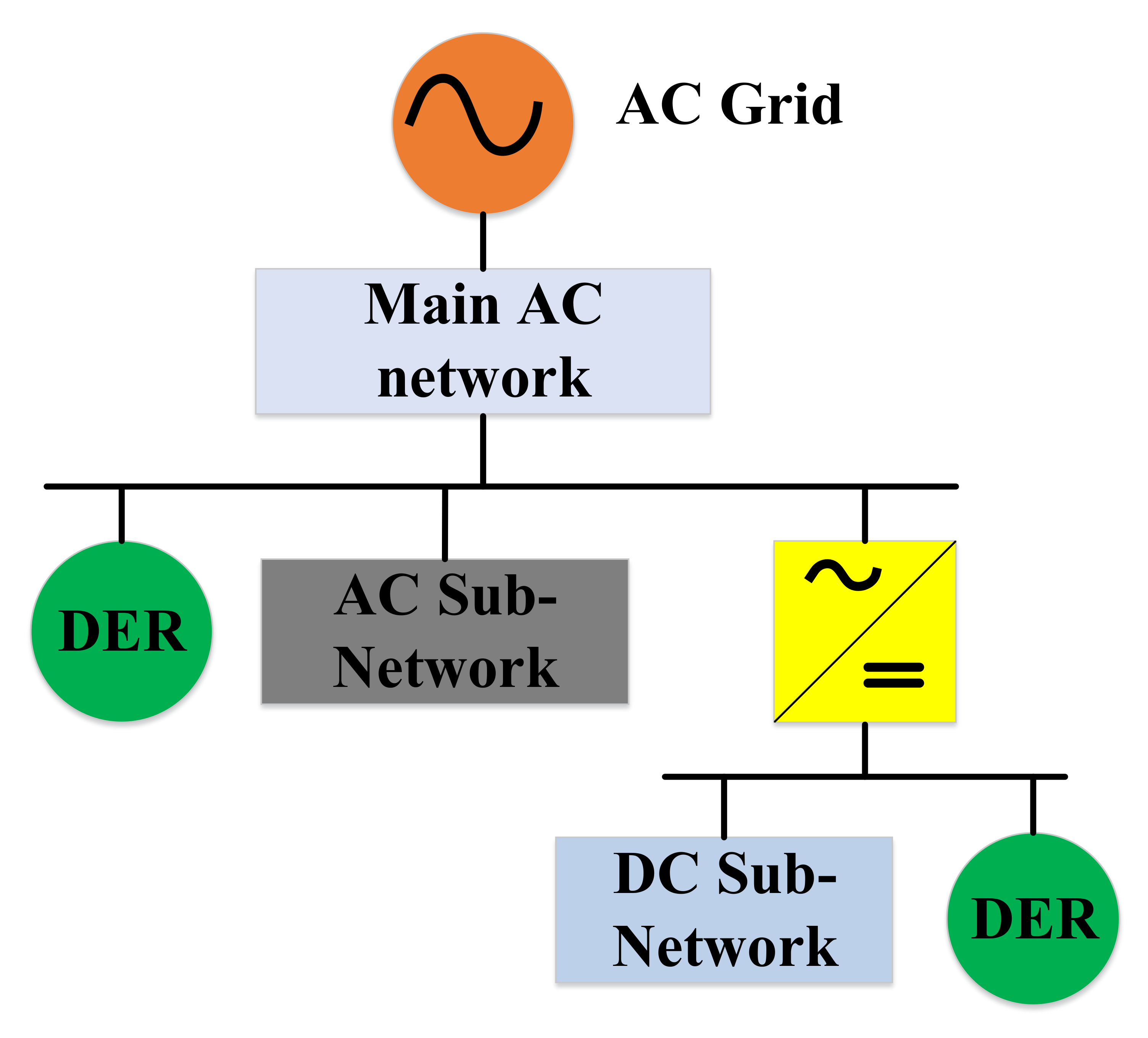
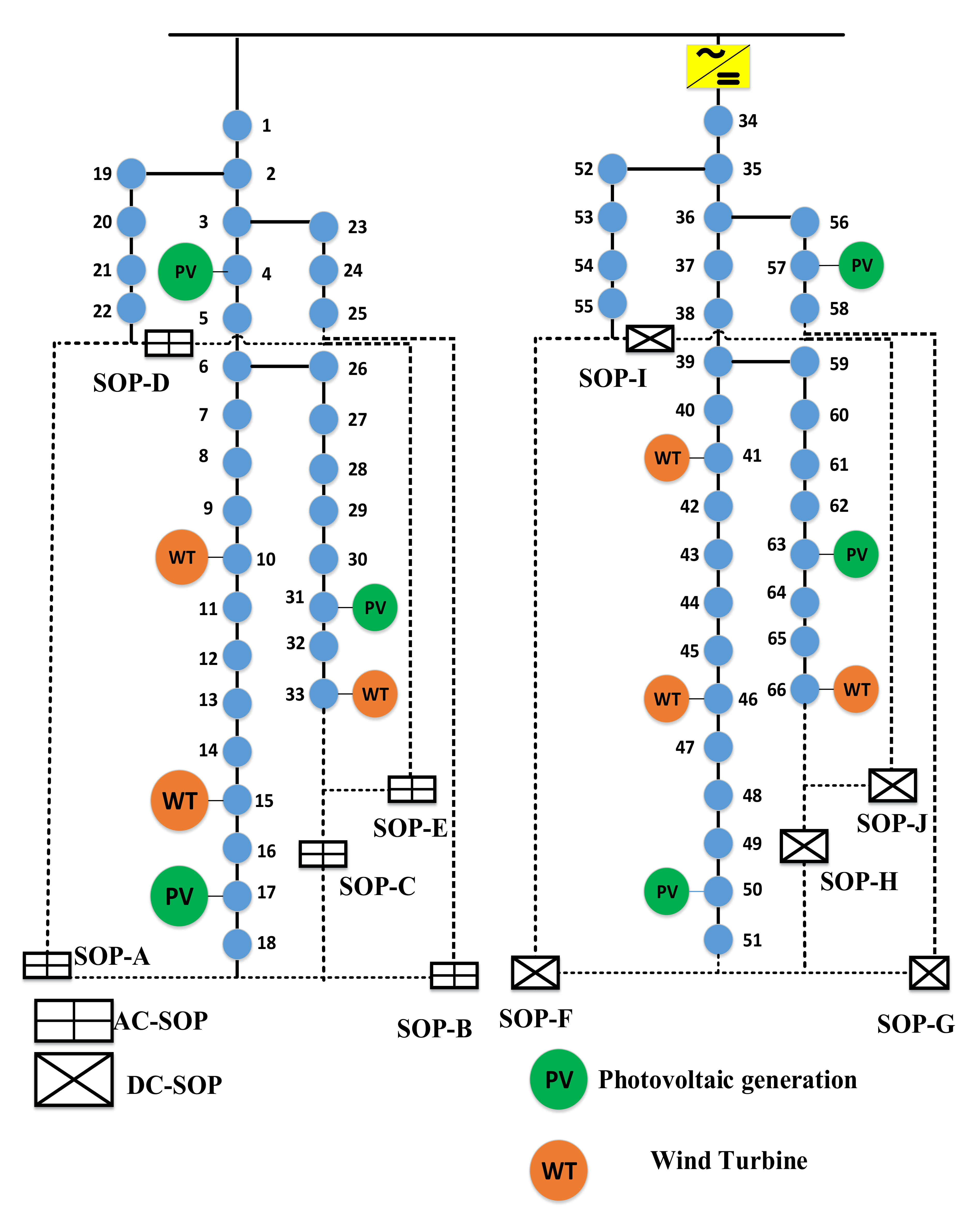
2.1. Description of the Generic AC-DC Hybrid Distribution Network
2.2. Modelling of SOP
- (1)
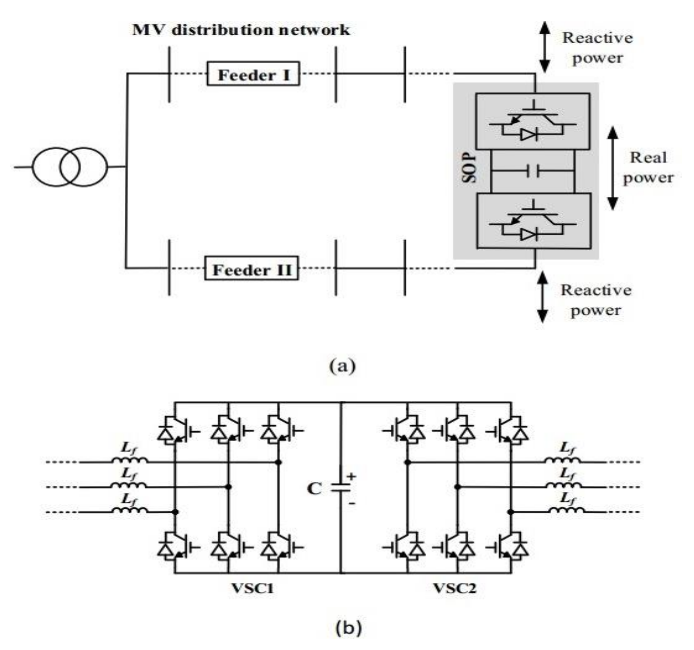
- AC-SOP: Figure 2 illustrates the single line representation of the hybrid AC-DC distribution network with AC-SOP. Back-to-back VSCs are used for the construction of AC-SOP which are utilized for the interconnection of the feeder endpoints in the two AC distribution sub-networks. The ability of the AC-SOP is to control the active and reactive power under different power flow control modes [11].
- (2)
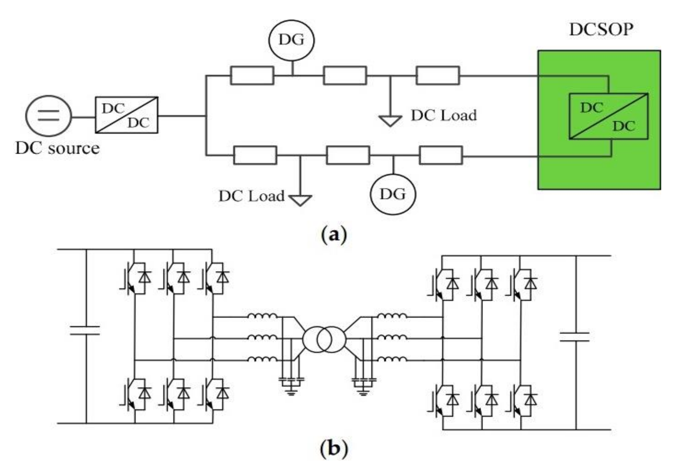
- DC-SOP: Similarly, DC-SOP is also located at the end of the DC distribution network feeders. Figure 3 shows the single line diagram of the DC soft open point (DC-SOP) in the AC-DC hybrid distribution network.
3. Problem Formulation
3.1. Power Balance Equations
3.2. Voltage and Line Parameters
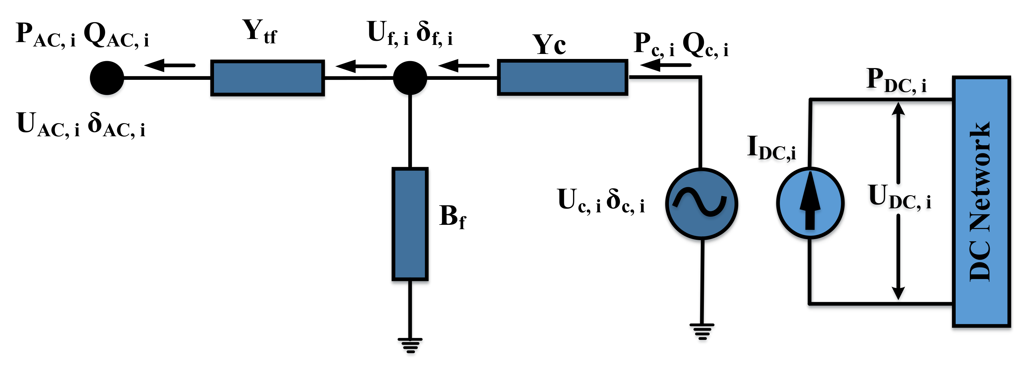
3.3. AC-DC Converter Modeling
3.4. Constraints of SOP
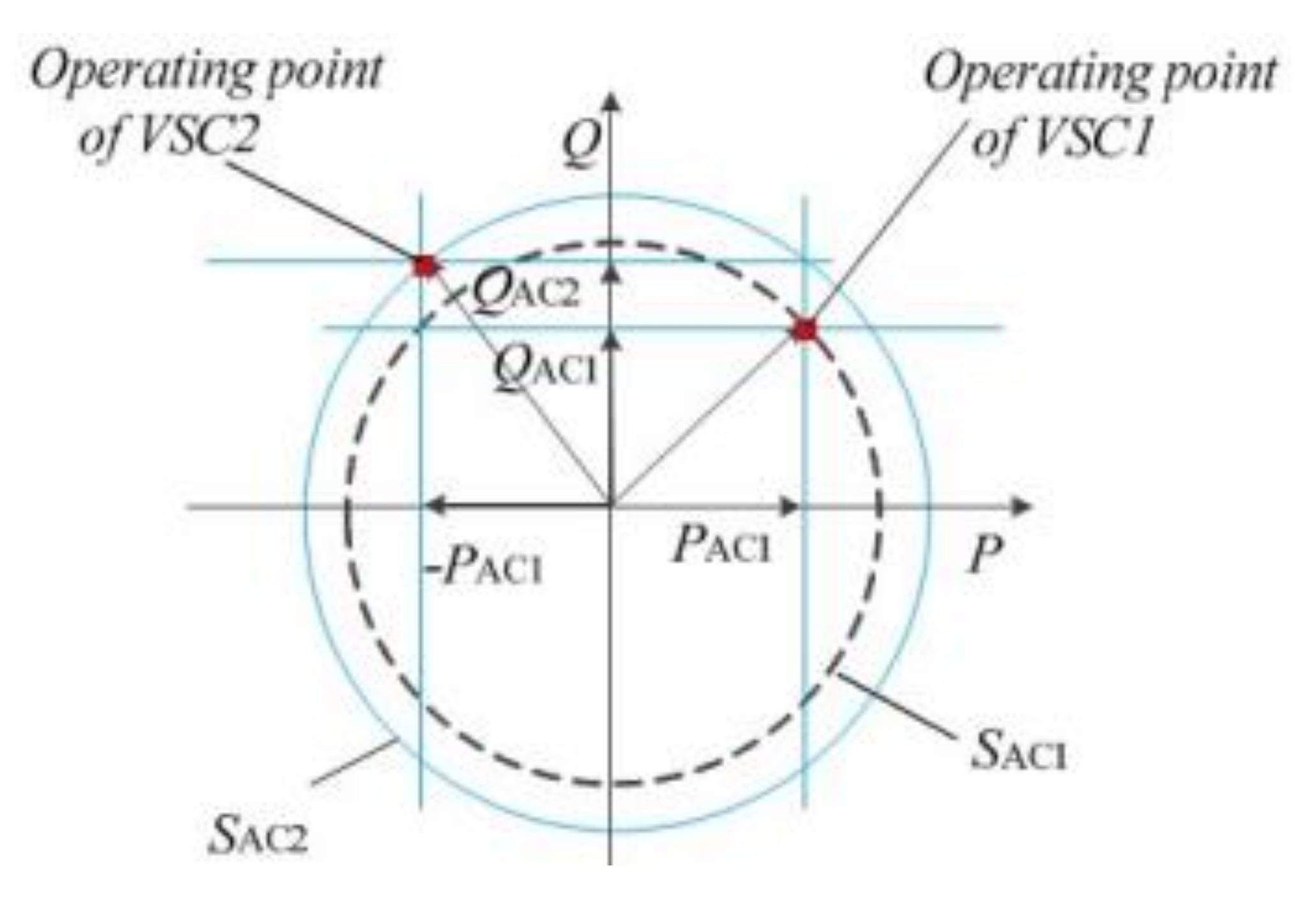
- (1)
- AC-SOP constraints: The operation of the AC-SOP is shown in Figure 5. In the power flow control mode [11], both the VSCs independently generate the voltage waveforms, which effectively results in a full control of the power at the two AC terminals of the VSCs. In this configuration of the AC-SOP, three variables are independently controlled, i.e., the active power PAC1 output of VSC1 and the reactive power outputs QAC1, and QAC2 of the two VSCs, respectively.
- (2)
- DC-SOP constraints: The DC-SOP operates in the constant active power control mode, as no reactive power is involved in the DC network. The constraints for the operation of a DCSOP can be represented as:
4. Network Reconfiguration Scheme and Case Study
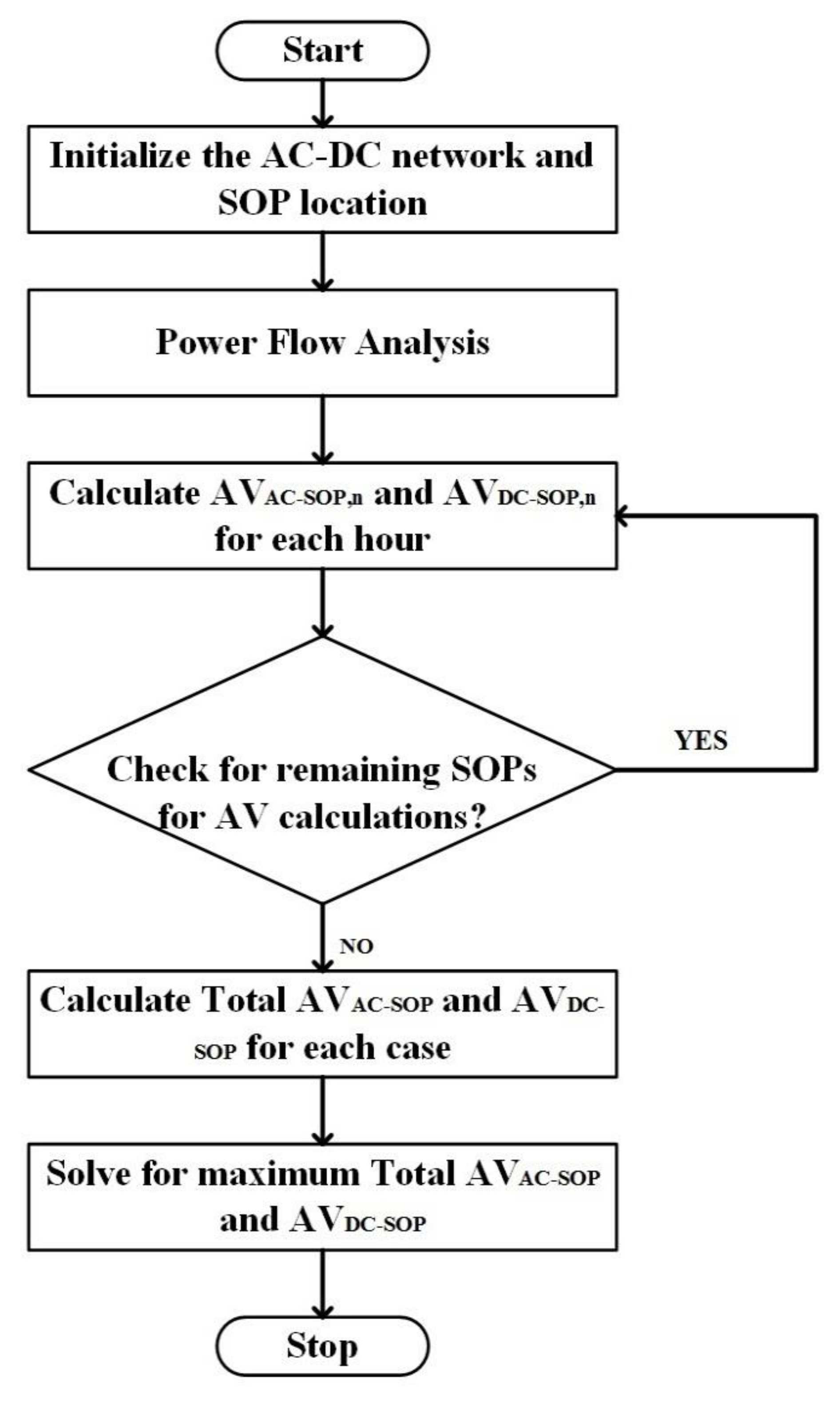
4.1. SOP/Loop Selection Algorithm for Network Reconfiguration
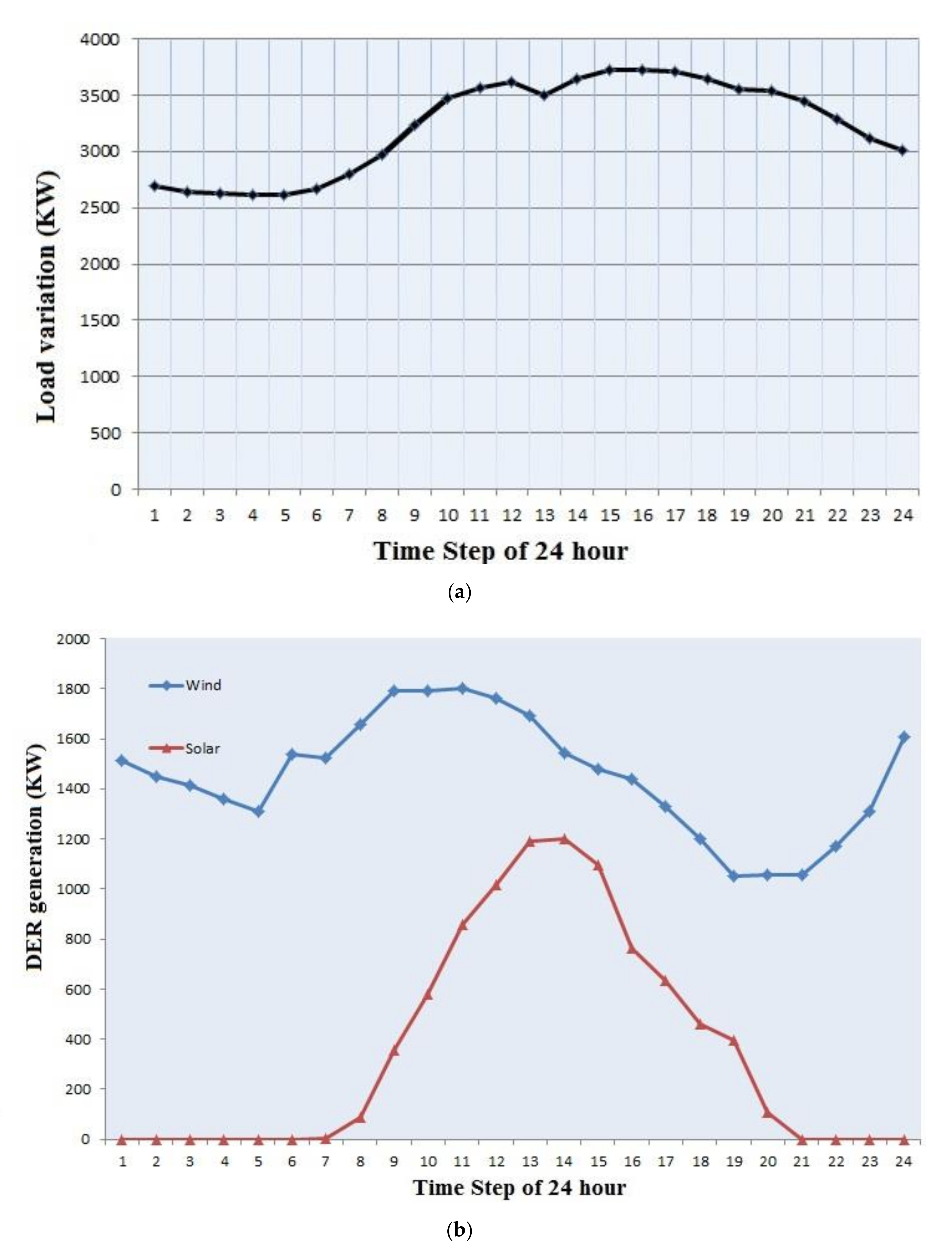
4.2. Case Study
4.3. Simulation Result
5. Conclusions
Author Contributions
Funding
Data Availability Statement
Conflicts of Interest
References
- Exposito, A.G.; Conejo, A.J.; Canizares, C.A. Electric Energy Systems Analysis and Operation; CRC Press: Boca Raton, FL, USA, 2008. [Google Scholar]
- Kalashani, M.B.; Nazarpour, D. New Symmetric and Hybrid Multilevel Inverter Topology Employed in Solar Energy Systems. Trans. Electr. Electron. Mater. 2018, 19, 304. [Google Scholar] [CrossRef]
- Elsayed, A.T.; Mohamed, A.A.; Mohammed, O.A. DC microgrids and distribution systems: An overview. Electr. Power Syst. Res. 2015, 119, 407–417. [Google Scholar] [CrossRef]
- Khan, M.O.; Jamali, S.Z.; Noh, C.-H.; Gwon, G.-H.; Kim, C.-H. A Load Flow Analysis for AC/DC Hybrid Distribution Network Incorporated with Distributed Energy Resources for Different Grid Scenarios. Energies 2018, 11, 367. [Google Scholar] [CrossRef]
- Zhu, Z.; Liu, D.; Liao, Q.; Tang, F.; Zhang, J.; Jiang, H. Optimal Power Scheduling for a Medium Voltage AC/DC Hybrid Distribution Network. Sustainability 2018, 10, 318. [Google Scholar] [CrossRef]
- Nguyen, P.H.; Kling, W.L.; Ribeiro, P.F. Smart power router: A flexible agent-based converter interface in active distribution networks. IEEE Trans. Smart Grid 2011, 2, 487–495. [Google Scholar] [CrossRef]
- Cong, P.; Tang, W.; Lou, C.; Zhang, B.; Zhang, X. Multi-stage coordination optimisation control in hybrid AC/DC distribution network with high-penetration renewables based on SOP and VSC. J. Eng. 2019. [Google Scholar] [CrossRef]
- Qu, Q.; Xu, D.; Zhai, Z.; Li, Q.; Zhang, W. Research on Development Technology of AC/DC Hybrid Distribution Network Construction in Smart Grid. IOP Conf. Ser.: Earth Environ. Sci. 2020, 10, 558. [Google Scholar] [CrossRef]
- Long, C.; Wu, J.; Thomas, L.; Jenkins, N. Optimal Operation of Soft Open Points in Medium Voltage Electrical Distribution Networks with Distributed Generation. Appl. Energy 2016, 184, 427–437. [Google Scholar] [CrossRef]
- Ji, H.; Wang, C.; Li, P.; Ding, F.; Wu, J. Robust Operation of Soft Open Points in Active Distribution Networks with High Penetration of Photovoltaic Integration. IEEE Trans. Sustain. Energy 2018, 10, 280–289. [Google Scholar] [CrossRef]
- Cao, W.; Wu, J.; Jenkins, N.; Wang, C.; Green, T. Operating Principle of Soft Open Points for Electrical Distribution Network Operation. Appl. Energy 2016, 164, 245–257. [Google Scholar] [CrossRef]
- Chub, A.; Vinnikov, D.; Blaabjerg, F.; Peng, F. A review of galvanically isolated impedance-source DC–DC converters. IEEE Trans. Power Electron. 2016, 31, 2808–2828. [Google Scholar] [CrossRef]
- Romero-Ramos, E.; Gómez-Expósito, A.; Marano-Marcolini, A.; Maza-Ortega, J.M.; Martinez-Ramos, J.L. Assessing the loadability of active distribution networks in the presence of DC controllable links. IET Gener. Transm. Distrib. 2011, 5, 1105–1113. [Google Scholar] [CrossRef]
- Bloemink, J.M.; Green, T.C. Benefits of distribution-level power electronics for supporting distributed generation growth. IEEE Trans. Power Del. 2013, 28, 911–919. [Google Scholar] [CrossRef]
- Daelemans, G.; Srivastava, K.; Reza, M.; Cole, S.; Belmans, R. Minimization of steady-state losses in meshed networks using VSC HVDC. In Proceedings of the 2009 IEEE Power & Energy Society General Meeting, Calgary, AB, Canada, 26–30 July 2009. [Google Scholar]
- Beerten, J.; Cole, S.; Belmans, R. Generalized steady-state VSC MTDC model for sequential AC/DC power flow algorithms. IEEE Trans. Power Syst. 2012, 27, 821–829. [Google Scholar] [CrossRef]
- Cole, S.; Beerten, J.; Belmans, R. Generalized dynamic VSC MTDC model for power system stability studies. IEEE Trans. Power Syst. 2010, 25, 1655–1662. [Google Scholar] [CrossRef]
- Go, H.-S.; Kim, J.-H.; Kim, E.-S.; Kim, C.-H. A study on the voltage sag during the EVs charging considering domestic data. J. Korean Inst. Illum. Electr. Install. Eng. 2015, 29, 37–46. [Google Scholar] [CrossRef]
- Draxl, C.; Clifton, A.; Hodge, B.-M.; McCaa, J. The wind integration national dataset (wind) toolkit. Appl. Energy 2015, 151, 355–366. [Google Scholar] [CrossRef]
- Sengupta, M.; Xie, Y.; Lopez, A.; Habte, A.; Maclaurin, G.; Shelby, J. The National Solar Radiation Data Base (NSRDB). Renew. Sust. Energ. Rev. 2018, 89, 51–60. [Google Scholar] [CrossRef]


| Control Modes | VSC1 | VSC2 |
|---|---|---|
| 1 | PDC_VSC1 control | UAC_VSC2 control |
| 2 | UAC_VSC1 control | PDC_VSC2 control |
| AC-SOP | DC-SOP | ||
|---|---|---|---|
| Case | SOP Location | Case | SOP Location |
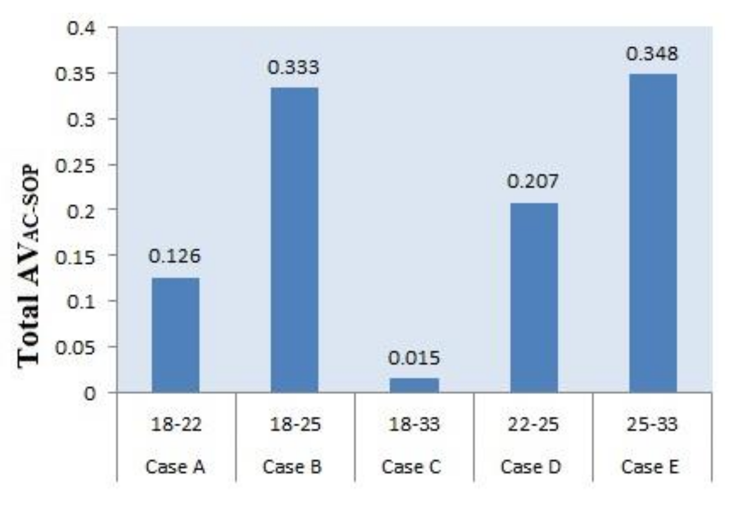
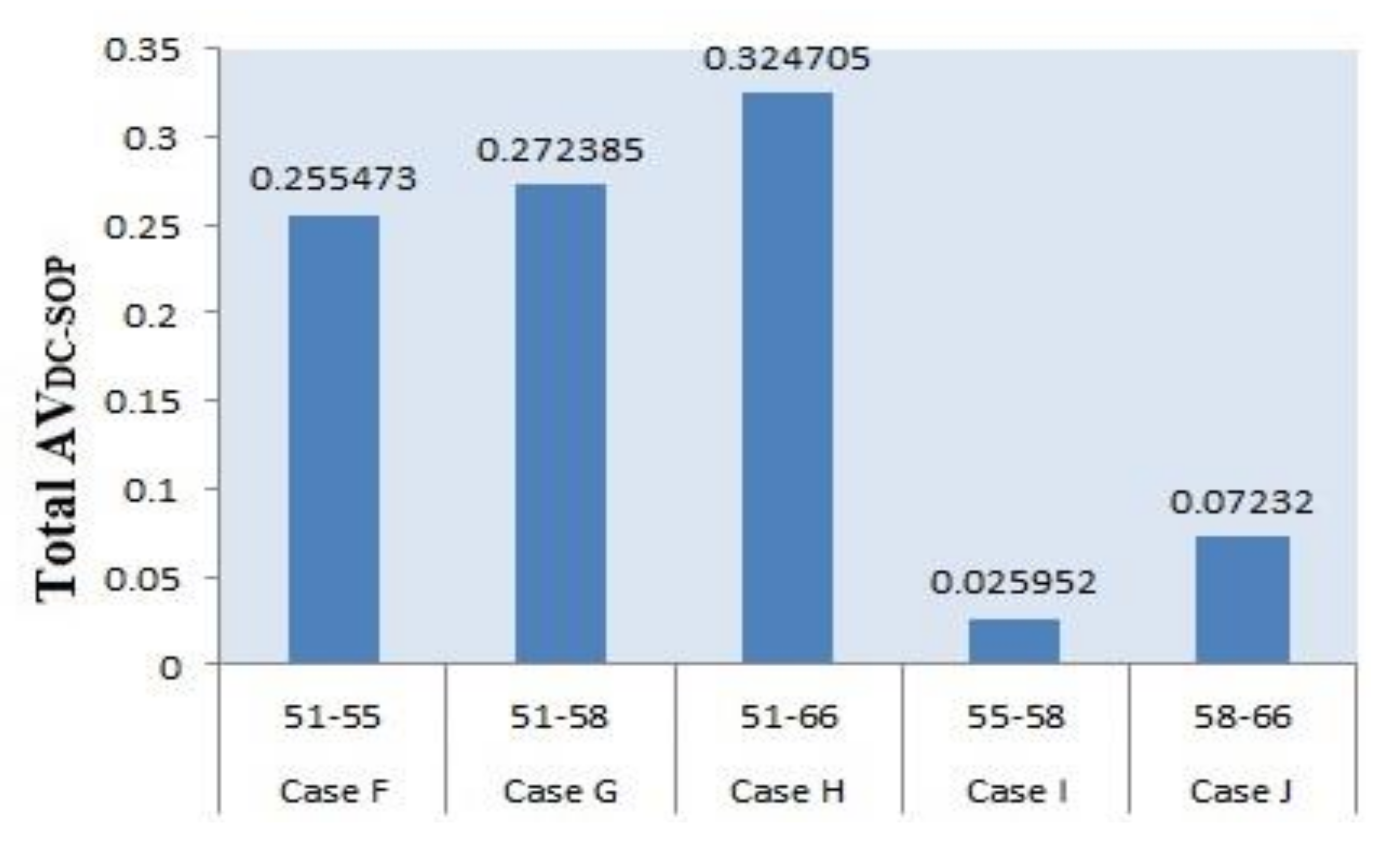
| Case A | 18–22 | Case F | 51–55 |
| Case B | 18–25 | Case G | 51–58 |
| Case C | 18–33 | Case H | 51–66 |
| Case D | 22–25 | Case I | 55–58 |
| Case E | 25–33 | Case J | 58–66 |
| AC-SOP | No SOP | Case A | Case B | Case C | Case D | Case E |
|---|---|---|---|---|---|---|
| AVAC-SOP | 0 | 0.126 | 0.333 | 0.015 | 0.207 | 0.348 |
| AC losses (kWh) | 374.6 | 371.04 | 366.72 | 371.28 | 369.84 | 363.36 |
| AC losses reduction (%) | 0 | 0.950 | 2.103 | 0.886 | 1.270 | 3.000 |
| DC losses (kWh) | 273.19 | 273.193 | 273.193 | 273.193 | 273.193 | 273.193 |
| Overall losses (kWh) | 647.79 | 644.233 | 639.913 | 644.473 | 643.033 | 636.553 |
| Overall losses reduction (%) | 0 | 0.549 | 1.216 | 0.512 | 0.734 | 1.735 |
| Grid power (kWh) | 1400.46 | 1399.92 | 1399.2 | 1399.92 | 1399.44 | 1398.96 |
| DC-SOP | No SOP | Case F | Case G | Case H | Case I | Case E |
|---|---|---|---|---|---|---|
| AVDC-SOP | 0 | 0.255 | 0.272 | 0.324 | 0.025 | 0.072 |
| AC losses (kWh) | 374.6 | 374.6 | 374.6 | 374.6 | 374.6 | 374.6 |
| DC losses (kWh) | 273.193 | 271.472 | 271.297 | 270.777 | 272.523 | 272.348 |
| DC losses reduction (%) | 0 | 0.630 | 0.694 | 0.886 | 0.245 | 0.309 |
| Overall losses (kWh) | 647.79 | 646.072 | 645.897 | 645.372 | 647.123 | 646.948 |
| Overall losses reduction (%) | 0 | 0.265 | 0.292 | 0.373 | 0.103 | 0.130 |
| Grid power (kWh) | 1400.46 | 1400.88 | 1402.08 | 1400.64 | 1400.16 | 1400.4 |
Publisher’s Note: MDPI stays neutral with regard to jurisdictional claims in published maps and institutional affiliations. |
© 2021 by the authors. Licensee MDPI, Basel, Switzerland. This article is an open access article distributed under the terms and conditions of the Creative Commons Attribution (CC BY) license (http://creativecommons.org/licenses/by/4.0/).
Share and Cite
Khan, M.O.; Wadood, A.; Abid, M.I.; Khurshaid, T.; Rhee, S.B. Minimization of Network Power Losses in the AC-DC Hybrid Distribution Network through Network Reconfiguration Using Soft Open Point. Electronics 2021, 10, 326. https://doi.org/10.3390/electronics10030326
Khan MO, Wadood A, Abid MI, Khurshaid T, Rhee SB. Minimization of Network Power Losses in the AC-DC Hybrid Distribution Network through Network Reconfiguration Using Soft Open Point. Electronics. 2021; 10(3):326. https://doi.org/10.3390/electronics10030326
Chicago/Turabian StyleKhan, Muhammad Omer, Abdul Wadood, Muhammad Irfan Abid, Tahir Khurshaid, and Sang Bong Rhee. 2021. "Minimization of Network Power Losses in the AC-DC Hybrid Distribution Network through Network Reconfiguration Using Soft Open Point" Electronics 10, no. 3: 326. https://doi.org/10.3390/electronics10030326
APA StyleKhan, M. O., Wadood, A., Abid, M. I., Khurshaid, T., & Rhee, S. B. (2021). Minimization of Network Power Losses in the AC-DC Hybrid Distribution Network through Network Reconfiguration Using Soft Open Point. Electronics, 10(3), 326. https://doi.org/10.3390/electronics10030326