Abstract
In a battery management system (BMS), battery equalizer is used to achieve voltage consistency between series connected battery cells. Recently, serious inconsistency has been founded to exist in retired batteries, and traditional equalizers are slow or inefficient to handle the situation. The multicell-to-multicell (MC2MC) topology, which can directly transfer energy from consecutive strong cells to consecutive weak cells, is promising to solve the problem, but its performance is limited by the existing converter. Therefore, this paper proposes an enhanced MC2MC equalizer based on a novel bipolar-resonant LC converter (BRLCC), which supports flexible and efficient operation modes with stable balancing power, can greatly improve the balancing speed without much sacrificing the efficiency. Mathematical analysis and comparison with typical equalizers are provided to illustrate its high balancing speed and good efficiency. An experimental prototype for 8 cells is built, and the balancing powers under different operation modes are from 1.426 W to 12.559 W with balancing efficiencies from 84.84% to 91.68%.
1. Introduction
Lithium-ion batteries are the first-choice candidate as power source for electric vehicles (EVs), hybrid electric vehicles (HEVs) and many other energy storage systems (ESSs) due to their high specific energy, high energy density, and low self-discharge rate [1,2,3]. To meet the high voltage requirement of these applications, lithium-ion batteries have to be connected in series [4,5,6], which means the currents flowing through each cell become strictly equal. However, available capacities (which are the integrals of the current) among cells tend to be various because of manufacturing tolerances, temperature difference across the pack, and differences in self-discharge rate [7,8]. This variety of capacity will lead to some cells’ overcharge during charging process or lead to some cells’ over-discharge during discharging process [9]. To avoid the destructive overcharge or over-discharge of lithium-ion batteries [10], the pack normally has to end the charging/discharging process before it is fully charged/discharged, which means its capacity cannot be fully utilized [11,12]. This phenomenon can even get more serious after many charging and discharging cycles [13,14], and therefore cannot be permanently guaranteed by an initial selection of equal battery cells [15].
The battery management system (BMS), which is responsible for ensuring the batteries’ safety, reliability, performance and service life [16], should deal with this imbalance problem using equalization techniques. The equalization techniques can be mainly divided into passive methods and active methods [4,17]. Passive methods usually transfer the energy from the strong cells with high voltages to heat by shunting resistors, which are easy and cheap to implement, can prevent the overcharge of cells but may cause extra thermal problem [18]. Active methods transfer the energy from the strong cells to the weak cells by using energy storage elements, so the imbalanced energy will not be wasted and the capacity of the pack can be improved [15,19].
Recently, the equalization techniques are facing new challenges because great numbers of lithium-ion batteries are going to be retired from electric vehicles [20,21]. These retied batteries, though cannot meet the strict mileage requirement of EVs, are sufficient for safe reuse in applications such as ESSs for wind or solar power [22] and can bring great economic and environmental benefits. However, the imbalance between the retired batteries is more serious than that of the new batteries [20]. Moreover, it is founded that neighboring consecutive cells tend to be in need of charge or discharge simultaneously [23]. A plausible reason is that the ambient temperature of neighboring cells is similar, making them have a similar capacity degradation [17].
In this case, existing equalizers will suffer from slow balancing speed or low balancing efficiency. Figure 1 shows an example when several consecutive high-voltage battery B1, B2, and B3 are in need of discharge and are set as the equalization’s source group, and a low-voltage battery Bn is in need of charge and is set as the equalization’s target group. Adjacent-cell-to-cell (AC2C) equalizers [24,25,26] can realize balance between two adjacent cells, but the energy must be transferred through multiple cells between the source group and target group. So the energy of B1 have to be delivered through E1–En−1 before eventually sent to Bn (see Figure 1a), leading to a slow balancing speed and low efficiency. Direct cell-to-cell (DC2C) equalizers [18,27,28,29,30] can realize direct equalization between any two cells, and they used to be considered as the quickest and most efficient topology [31]. However, the source and target of equalization can only be single cell, which means the rest cells have to wait. So, when B1 is delivering energy through E1 to Bn, the B2 and B3 have to queue (see Figure 1b), leading to a slow balancing speed. Cell-to-pack (C2P) equalizers [32,33,34,35] deliver the energy of a single cell to the whole pack and can realize fast equalization when only a few cells are strong. However, this will be very inefficient and slow when only a single cell is weak. In this case B1, B2, and B3 not only have to queue, but also cannot directly transfer their energy to Bn (see Figure 1c). Pack-to-cell (P2C) equalizers [36,37,38] deliver the energy of the whole pack to a single cell, so B1, B2, and B3 can indirectly transfer their energy to Bn (see Figure 1d). However, in an opposite case when Bn has high voltage and B1, B2, and B3 have low voltage, the equalization will be very slow and inefficient just like the C2P equalizers. Besides, AC2C, C2P and P2C equalizers will suffer from extra energy loss due to the unexpected charge of strong cells, unexpected discharge of weak cells, and repeated charge/discharge of irrelevant cells such as the Bn−1 [23].
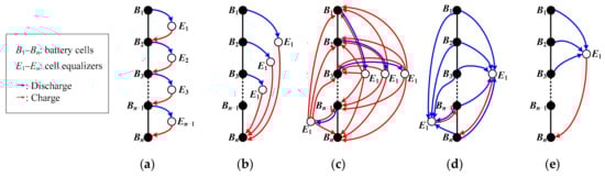
Figure 1.
Balancing paths of different equalizers under the assumption that B1, B2 and B3 are equally strong, Bn is weak, and other cells are balanced. (a) AC2C. (b) DC2C. (c) C2P. (d) P2C. (e) MC2MC.
Therefore, a multicell-to-multicell (MC2MC) topology has been discovered in [23], which can directly transfer the energy from the consecutive high-voltage cells to target group Bn (see Figure 1e). So, the B1, B2 and B3 do not have to queue, and the energy is directly transferred to Bn, leading to a great improvement in balancing speed and the elimination of unexpected energy loss.
Furthermore, the performance of MC2MC topology will highly depend on the specific converter that used to construct the equalizer. First, after removing the unexpected energy loss caused by the topology, the conversion power and efficiency of the converter itself are important to maximize the capacity of the battery pack and to reduce the generation of heat. Second, the converter should be able to realize both step-up conversion and step-down conversion to provide flexible operation modes that cover as many situations as possible. For example, if only B1 has higher voltage, and Bn−1 and Bn have lower voltages, the equalizer has to transfer energy from the source group with a voltage of VBS = VB1 to the target group with voltage VBT = VB(n−1) + VBn, which means a step-up conversion is needed. We define this operation mode as one-cell-to-two-cell mode (1–2 mode) as shown in Figure 2b. Figure 2 also presents some potential operation modes including one-cell-to-one-cell mode (1–1 mode), one-cell-to-two-cell mode (1–2 mode), two-cell-to-one-cell mode (2–1 mode), two-cell-to-two-cell mode (2–2 mode), three-cell-to-one-cell mode (3–1 mode), and three-cell-to-two-cell mode (3–2 mode).
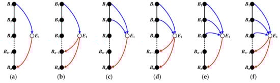
Figure 2.
Possible operation modes of a MC2MC equalizer. (a) 1–1 mode. (b) 1–2 mode. (c) 2–1 mode. (d) 2–2 mode. (e) 3–1 mode. (f) 3–2 mode.
However, the half-bridge LC converter (HBLCC) in [23] may suffer from low conversion power/efficiency in some cases and cannot realize step-up conversion. To better illustrate the reason, we can start from a MC2MC equalizer based on a simple switched-capacitor converter (SCC) shown in Figure 3. First, assume that VB4 = VB3 = VB2 > VB1. In each switching period, the capacitor firstly collects energy from B4, B3 and B2 through S4a and S1b (see Figure 3a). Then, the capacitor releases its energy to B1 through S1a and S0b (see Figure 3b). So, the energy is transferred from B4 + B3 + B2 to B1, realizing 3–1 mode equalization. However, if the situation is VB4 = VB3 = VB2 < VB1 and VB4 + VB3 + VB2 > VB1, the same operation will sill transfer the energy from B4 + B3 + B2 to B1, which obviously violates the spirit of equalization. Moreover, its balancing efficiency is as low as about 33% because the conversion efficiency of SCC is strictly equal to the ratio of output voltage to input voltage [39,40], and its balancing power will decrease dramatically when the voltage gap is low. The HBLCC equalizer proposed adds an inductor (see Figure 4a) to realize zero-current switching (ZCS), which helps to reduce the switching loss and the electromagnetic interference (EMI), has a very similar operation principle and performance with the SCC based equalizer. In other words, it is still incapable of maintaining good balancing efficiency and stable power over a wide voltage gain range as well as realizing step-up conversion to cover more situations.
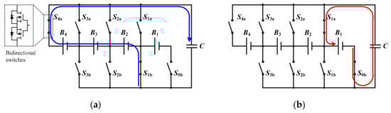
Figure 3.
Switching states of a MC2MC equalizer based on SCC. (a) Collect state. (b) Release state.
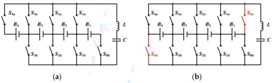
Figure 4.
Circuit comparison of MC2MC equalizers. (a) The equalizer based on HBLCC [23]. (b) The proposed equalizer based on BRLCC.
To improve the balancing power and enable more MC2MC MC operation modes to further accelerate the equalization, this paper proposes a novel bipolar-resonant LC converter (BRLCC) to construct an enhanced MC2MC equalizer. Compared to the HBLCC, the proposed BRLCC (see Figure 4b) introduces two extra bidirectional switches to form a symmetric switch matrix, which allows its LC resonant tank to resonant in a bipolar way and thus realize high/stable balancing power, good efficiency, and step-up conversion. The rest of this paper is organized as follows. In Section 2, the circuit topology, operation principle, mathematical model, and mathematical analysis of the proposed equalizer are introduced. Section 3 presents simulation comparison with typical equalizers. Section 4 introduces the experimental prototype, tests its balancing performance, and verifies its high balancing speed over other equalizers. Section 5 presents a systematical discussion, and Section 6 gives a conclusion.
2. Proposed Equalizer
2.1. Circuit Structure
The proposed BRLCC (see Figure 5) has a symmetric switch matrix, a LC resonant tank, and a diode protection network. The symmetric switch matrix consists of bidirectional switches (S0a–SNa are connected to BUSa, and S0b–SNb are connected to BUSb). The resonant tank consists of an inductor L, a capacitor C, and the total parasitic resistance RS. The diode protection network consists of four free-wheeling diodes D1–D4.
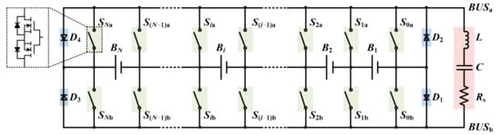
Figure 5.
Circuit structure of the proposed BRLCC equalizer for N cells.
The resonant tank collects energy from the consecutive strong cells (source group) through the symmetric switch matrix, and then releases the energy to the consecutive weak cells (target group). Driving signals with fixed switching frequency and duty cycle are adopted to control the circuit due to its resonant nature, making a simple control possible. All switches work with ZCS, which reduces the loss and EMI of the circuit and helps to increase switching frequency and reduce circuit volume.
Different from the SCC or HBLCC equalizer shown in Figure 3 and Figure 4a, the proposed BRLCC equalizer has 4 switching states in a switching period and will go through a startup process before it enters the steady-state. In the following subsections, we will introduce the steady-state operation, prove how the equalizer enters the steady-state, present the mathematical model, and finally illustrate how the proposed equalizer performs better than the HBLCC equalizer.
2.2. Operation Principle
Figure 6 presents the switching states along with the steady-state’s current flow of the proposed equalizer. For convenience, the battery pack is assumed to have 4 cells with VB4 = VB3 = VB2 < VB1, which is arranged to illustrate the 1–3 mode equalization. The voltage of target group and source group are VBS = VB1 and VBT = VB4 + VB3 + VB2, respectively.
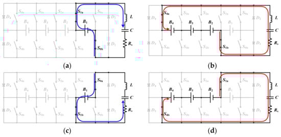
Figure 6.
Switching states and steady-state’s current flow of the proposed equalizer at VB4 = VB3 = VB2 < VB1. (a) Positive collect: state I. (b) Positive release: state II. (c) Negative collect: state III. (d) Negative release: state IV.
Figure 7 shows the equivalent input of LC resonant tank, and gives the steady-state’s waveforms. As shown in Figure 7a, the proposed equalizer has a similar equivalent input voltage Vin with the DC2C equalizer based on LC series resonant converter (LCSRC) in [28]. Two improvements should be acknowledged. First, the symmetrical switch matrix makes it possible to set VBS and VBT as the total voltage of consecutive strong cells or weak cells, which makes MC2MC equalization possible and greatly enhances the balancing speed. Second, the abandon of bridge network reduces the number of MOSFETs in the resonant loop from 8 to 4, which reduces the total parasite resistance RS and helps to achieve a higher balancing efficiency.
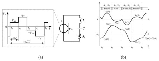
Figure 7.
Theoretical waveforms of the proposed equalizer at VBT ≈ 3VBS. (a) Equivalent input Vin of the LC resonant tank. (b) Steady-state’s waveforms including driving signals, inductor current iL, and capacitor voltage uC of the equalizer.
Figure 7b presents the steady-state’s waveforms, showing the inductor current iL resonates and charges/discharges the capacitor voltage uC to different voltage values at the end of each switching state. Detailed descriptions are as follows.
In state I [t0–t1]: the LC tank positively collects charges from VBS. Switches S1a and S0b are turned on with ZCS at t = t0, and turned off with ZCS at t = t1. Since UC(0) is lower than VBS, uC charges from UC(0) to UC(1), and the peak value of iL is IP(1).
In state II [t1–t2]: the LC tank positively releases charges to VBT. Switches S4a and S1b are turned on with ZCS at t = t1, and turned off with ZCS at t = t2. Since UC(1) is higher than VBT, uC discharges from UC(1) to UC(2), and the peak value of iL is IP(2).
In state III [t2–t3]: the LC tank negatively collects charges from VBS. Switches S1b and S0a are turned on with ZCS at t = t2, and turned off with ZCS at t = t3. Since UC(2) is negatively lower than −VBS, uC charges from UC(2) to UC(3), and the peak value of iL is IP(3).
In state IV [t3–t4]: the LC tank negatively releases charges to VBT. Switches S4b and S1a are turned on with ZCS at t = t3, and turned off with ZCS at t = t4. Since UC(3) is negatively higher than −VBT, uC discharges from UC(3) to UC(4), and the peak value of iL is IP(4).
2.3. Mathematical Model
After knowing the operation principle, the question may be what the values of UC(0) to UC(4) are, and why can we get them. To get the answer, we should first calculate the uC and iL according to the following differential equation:
where L is the inductance, C is the capacitance, RS is the total parasitic resistance.
During every state [ti–ti+1] (i = 0, 1, 2, 3), the initial condition is that uC = uC(ti) and iL = 0. If RS satisfies , then the differential Equation (1) can be solved as:
where , , .
Each state ends when iL reaches zero at t = ti+1, and the duration of the state is:
Then the terminal uC of each state can be calculated as:
where is a factor negatively correlated with ρ and Rs, and positively correlated with Zr:
To calculate the specific value of UC(0) to UC(4), Vin in (4) can be substituted with US, UT, −US, and −UT respectively for state I–IV to calculate UC(1) upon UC(0), calculate UC(2) upon UC(1), calculate UC(3) upon UC(2), and calculate UC(4) upon UC(3):
It also should be noticed that UC(0) = UC(4) in the steady-state, so the terminal capacitor voltage and peak inductor current in each state can be calculated as:
To prove that the equalizer will converge to this steady-state after startup, we can assume that uC(t0) ≠ UC(0) at the beginning, and the initial voltage error is defined as:
Then, in the end of state I, the uC will change to uC(t1) according to (5):
While in the steady-state we have:
By putting (12) into (11), we can get:
which shows that the voltage error at t = t1 is reduced by multiplying .
In the end of state II, III, and IV, we can similarly get:
Formulas (13)–(16) reveal that the absolute value of voltage error decays exponentially as:
For example, when L = 10 μH and Rs = 0.2 Ω, the time constant will be τ = 0.0001 s, which confirms that the equalizer will rapidly and automatically converge to the steady-state shown in Figure 7b, and we will certainly get the needed UC(0)–UC(4) to realize step-up conversion. This behavior is done by the bipolar resonant of the LC tank, and is quite different from that of the SCC or HBLCC equalizer.
Overall, the proposed equalizer will discharge the source group in state I/III. Meanwhile, the capacitor will collect the charge and let uC rise from UC(0) to UC(1) or negatively rise from UC(2) to UC(3). According to (8), it is obvious that UC(1) − UC(0) equals to UC(2) − UC(3). According to (4), the total duration of a switching period is 4Δt, so the average balancing power emitted by the source group can be calculated as:
Similarly, the proposed equalizer will charge the target group in state II/IV. The capacitor will release the charge and let uC fall from UC(1) to UC(2) or negatively fall from UC(3) to UC(4). So, the balancing power received by the target group is:
The balancing efficiency can be calculated as:
As can be seen from (19) and (20), 1–3 mode equalization is realized and the energy is transferred from the source group B1 to the target group B4 + B3 + B2. If we want the energy to be transferred from B4 + B3 + B2 to B1, we just need to exchange the source group and the target group. Furthermore, the source group and target group can both be any consecutive battery cells. Therefore, all MC2MC operation modes are now supported by the proposed BRLCC equalizer.
As can be seen from (20), the balancing efficiency is no longer as low as VBT/VBS but is also related to , which is positively correlated with Zr and negatively correlated with Rs. Figure 8 presents the balancing efficiency surface and power surface obtained from (20) and (19) as a function of Zr and RS. It is assumed that VBS = 4 V and VBT = 3.9 V because the 1–1 mode is the most basic operation mode among all MC2MC modes. It can be observed that, RS should be as small as possible to achieve high efficiency or high power because it consumes energy. After RS is determined at a small enough value such as 0.2 Ω, a larger Zr will lead a higher efficiency (see Figure 8a), and a smaller Zr will lead to higher balancing power (see Figure 8b). This allows us to adjust conversion efficiency and power by setting different Zr. In this paper, we set Zr = under the assumption of Rs = 0.2 Ω to provide an efficiency of about 90% and power of about 1.5 W in 1–1 mode.
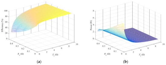
Figure 8.
The influence of Zr and Rs on balancing efficiency and power of the proposed equalizer at VBS = 4 V and VBT = 3.9 V. (a) Efficiency surface. (b) Power surface.
2.4. Comparative Analysis
For the MC2MC equalizer based on HBLCC in [23], when ignoring the switching loss, the balancing efficiency and power are given as:
Figure 9 compares the balancing efficiency and balancing power of the proposed BRLCC equalizer and the HBLCC equalizer in various MC2MC operation modes. For convenience, we assume VBS = 4 V, 8 V, 12 V and 16 V to illustrate the 1–X, 2–X, 3–X, 4–X mode respectively, where X is the number of target cells. The curves are based on (19)–(22), and are verified by simulation models built in PSIM (Power Simulation) 9.1.4.
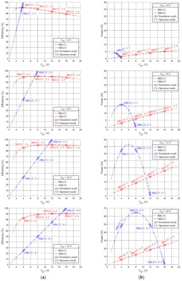
Figure 9.
Balancing efficiency and power comparison of the proposed BRLCC equalizer with HBLCC equalizer in different operation modes. (a) Balancing efficiency. (b) Balancing power.
Figure 9a compares the balancing efficiency. When the source group contains one cell and VBS = 4 V, the proposed BRLCC equalizer can realize 1–1, 1–2, 1–3, and 1–4 operations mode, while the HBLCC equalizer can only realize 1–1 operation mode. Moreover, the efficiency of HBLCC drops rapidly when the voltage gap between VBT and VBS becomes large. When VBS = 8 V, the HBLCC equalizer can realize two operations modes, but the efficiency of 2–1 mode is as low as 50%. When VBS = 12 V, the HBLCC equalizer can realize three operations modes, but the efficiencies of 3–1 and 3–2 mode are as low as 33% and 66%, respectively. When VBS = 16 V, the HBLCC equalizer can realize four operations modes, but the efficiencies of 4–1, 4–2, and 4–3 modes are low as 25%, 50%, and 75%, respectively. In comparison, the proposed BRLCC equalizer can support all operation modes of MC2MC equalization, and the efficiencies are maintained at a high level.
Figure 9b then compares the balancing power. When VBS = 4 V, the power of HBLCC drops quickly to zero around VBT = 4 V, which means its balancing speed will be very slow when the voltage gap is small. In comparison, BRLCC not only supports 1–1, 1–2, 1–3 and 1–4 modes, but also keep a relatively stable and high balancing power within each mode’s voltage range. Similar phenomenon can also be observed at VBS = 8 V, 12 V and 16 V. Considering Figure 9a,b together, it can be noticed that the HBLCC always have very low balancing power when the efficiency is high, while the BRLCC can realize good balancing power with balancing efficiency higher than 80%. Overall, the proposed BRLCC equalizer can achieve higher and more stable balancing power than the HBLCC equalizer.
3. Simulation Comparison with Conventional Equalizers
In this section, we use simulation to quantitatively compare the proposed MC2MC equalizer based on BRLCC with three typical equalizers: the AC2C equalizer based on quasi-resonant switched-capacitor converter (QRSSC) [24], the DC2C equalizer based on LCSRC [28], and the MC2MC equalizer based on HBLCC [23].
Figure 10 presents these equalizers for eight cells. These simulation models are built in PSIM 9.1.4, and they have the same circuit parameters of L = 10 μH, C = 1 μF. The parasitic resistance of LC tank is set as 0.16 Ω, and each MOSFET is assumed to be ideal with Rds(on) = 0.01 Ω. So the total RS of these equalizers are 0.18 Ω, 0.24 Ω, 0.2 Ω, and 0.2 Ω, respectively. Eight capacitors are used to simulate the batteries [3,24], and their capacitances are set as 0.01 F to reduce the simulation time.
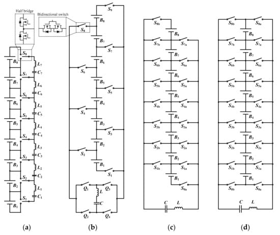
Figure 10.
Circuit comparison of different equalizers for 8 cells. (a) AC2C equalizer based on QRSCC. (b) DC2C equalizer based on LCSRC. (c) MC2MC equalizer based on HBLCC. (d) Proposed MC2MC equalizer based on BRLCC.
Figure 11 presents the control flowcharts for these simulation models. The equalization will stop after the maximum voltage difference of the cells (which equals to VBH − VBL) is less than 0.01 V. Figure 11a shows the AC2C equalizer based on QRSCC is simple as it realizes automatic equalization. Figure 11b shows the DC2C and MC2MC equalizers have the same control flowchart, and the only difference is that when selecting the source group and target group, the DC2C equalizer can only choose a single strongest/weakest cell, while the MC2MC equalizers can select consecutive strong/weak cells. Moreover, as analyzed in former section, the proposed BRLCC equalizer can achieve even more MC2MC modes than the HBLCC equalizer because step-up conversion can be realized. To achieve an acceptable balancing efficiency of over 85% in the simulation, the MC2MC equalizer based on HBLCC is only enabled with 1–1, 2–2, 3–3 operation modes, while the proposed MC2MC equalizer based on BRLCC is enabled with 1–1, 1–2, 1–3, 2–1, 2–2, 2–3, 3–1, 3–2, 3–3 operation modes.
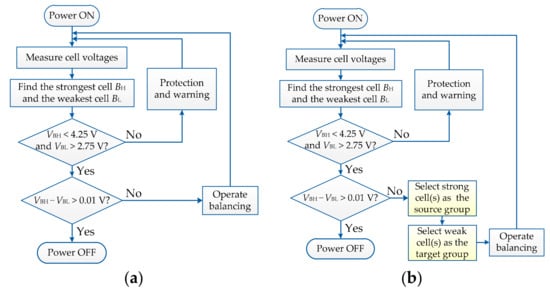
Figure 11.
Control algorithms of the simulation models. (a) QRSCC equalizer. (b) The other three equalizers.
Figure 12a,c,e,g present the simulation results for the equalizers with initial voltage #1 of VB1 = 3.50 V, VB2 = 3.48 V, VB3 =3.46 V, VB4 = 3.44 V, VB5 = 3.42 V, VB6 = 3.40 V, VB7 = 3.10 V, and VB8 = 3.00 V. This initial voltage distribution is arranged to simulate the near-empty situation where B7 and B8 need urgent charge. In Figure 12a, the QRSCC equalizer takes the longest time of 0.22481 s to realize equalization. This phenomenon is caused by two reasons. First, its AC2C structure cannot transfer energy directly. Second, its balancing power decreases rapidly at small voltage gap. In Figure 12c, the LCSRC equalizer is much faster with a balancing time of 0.01796 s. It not only transfers the energy directly, but also maintains almost stable balancing power in the whole equalization process. In Figure 12e, the HBLCC equalizer realizes fast equalization at the beginning due to its MC2MC topology. Its maximum voltage differences at 0.005 s and 0.01 s are 166 mV and 86 mV respectively, which is much smaller than the 297 mV and 182 mV of LCSRC equalizer. However, its equalization time of 0.02978 s is not the shortest because its balancing power decreases rapidly in the later stage of the balancing process. In Figure 12g, the proposed BRLCC equalizer realizes fastest equalization within 0.00962 s. It inherits the fast speed of MC2MC topology and maintains high balancing power during the whole balancing process.
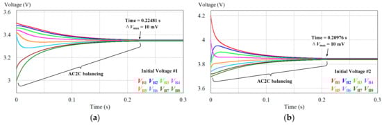
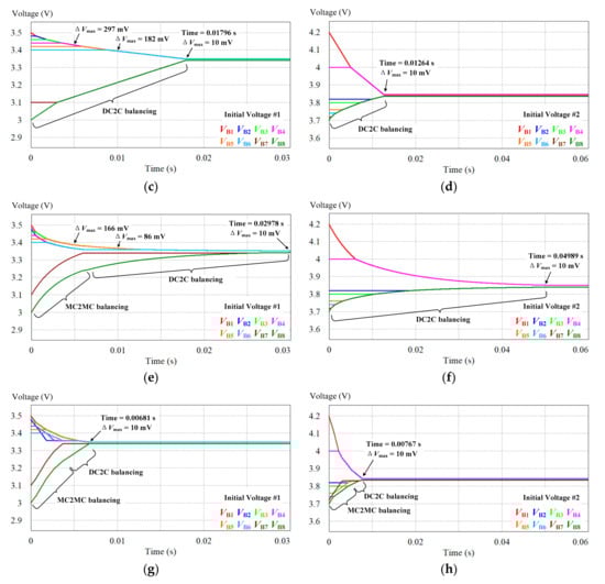
Figure 12.
Voltage trajectories of different equalizers with initial voltages #1 and #2. (a,b) AC2C equalizer based on QRSCC. (c,d) DC2C equalizer based on LCSRC. (e,f) MC2MC equalizer based on HBLCC. (g,h) Proposed MC2MC equalizer based on BRLCC.
Figure 12b,d,f,h present the simulation results with initial voltage #2 of VB1 = 4.20 V, VB2 = 3.82 V, VB3 = 3.80 V, VB4 = 4.00 V, VB5 = 3.76 V, VB6 = 3.74 V, VB7 = 3.72 V, and VB8 = 3.70 V. This initial voltage distribution is arranged to simulate the near-full situation where B1 and B4 need urgent discharge. In Figure 12b, the QRSCC equalizer takes the longest time of 0.20976 s to realize equalization. In Figure 12d, the LCSRC equalizer is still good and consumes 0.01264 s. In Figure 12f, the HBLCC equalizer degenerates into a conventional DC2C equalizer since it is incapable of realizing step-up modes. Therefore, it consumes a much longer time of 0.04989 s. In Figure 12h, the proposed equalizer takes the shortest time of 0.00767 s, which is due to its support for more kinds of MC2MC operation modes.
Table 1 compares the balancing time and total energy transfer efficiency in simulation. In initial voltage #1, the balancing speed of the proposed equalizer is about 33 times of the QRSCC equalizer, 2.6 times of the LCSRC equalizer, and 4 times of the HBLCC equalizer. In initial voltage #2, the balancing speed of the proposed equalizer is about 27 times of the QRSCC equalizer, 1.6 times of the LCSRC equalizer, and 6 times of the existing HBLCC equalizer. The total energy transfer efficiencies of the proposed equalizer are 89.15% and 86.86%, which are similar to the LCSRC equalizer but slightly lower than the other two equalizers. It should be noted that this slight decrease in efficiency is reasonable because when the balancing current increases, the ohmic loss () will increase faster than the average balancing power (). Considering that the increase in balancing speed is much more significant than the decrease in balancing efficiency, such trade-off is worthwhile.

Table 1.
Simulation comparison of different equalizers with initial voltages #1 and #2.
4. Experimental Results
Figure 13 shows the experimental prototype for 8 cells. The equalizer is composed of two boards (see Figure 13a), and each board can be connected to 4 cells (see Figure 13b). A DSP (TMS320F28335) controller is used to realize the MC2MC control, and it drives the equalizer through the driver boards. Table 2 presents the parameters of the prototype. The inductance/capacitance and equivalent series resistance (ESR) of the inductor and capacitor are measured by a Tonghui TH2832 LCR meter with accuracy of 0.05%. The internal resistances of the 18650 lithium-ion batteries are measured at about R0 ≈ 50 mΩ by a YAOREA YR1035+ battery internal resistance analyzer with accuracy of 0.5% ± 0.5 mΩ, and will slightly change with the state of charge (SOC) of the battery [16]. The RDS(on) of each IRF7351 MOSFET is less than 17.8 mΩ. So the total parasitic resistance can be approximated as RS ≈ (72.92 + 13.77 +17.8 × 4 + 49.5) mΩ ≈ 207.39 mΩ ≈ 0.2 Ω. The prototype also serves as a QRSCC equalizer or a HBLCC equalizer to produce the comparative data.
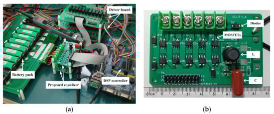
Figure 13.
Experimental prototype of the proposed BRLCC equalizer. (a) Platform. (b) A single board.
Table 2.
Parameters of the experimental prototype.
Figure 14 shows the experimental waveforms along with the simulated waveforms in different operation modes of the prototype. Figure 14a shows the inductor current iL is almost sinusoidal in each switching state and drops to zero during switching the states, which realizes ZCS and leads to a very clean current waveform without high frequency oscillation. The black simulated waveforms are in good agreement with the colored oscilloscope waveforms. The energy is transferred from the source group to the LC resonant tank in state I and III, and then transferred to the target group in state II and IV.
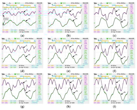
Figure 14.
Experimental and simulated waveforms of the proposed BRLCC equalizer in different operation modes. (a) 1–1. (b) 1–2. (c) 1–3. (d) 2–1. (e) 2–2. (f) 2–3. (g) 3–1. (h) 3–2. (i) 3–3.
Table 3 compares the measured data with theoretical values to prove the correctness of mathematical analysis. The voltages are measured by a Neware CT4008 battery testing system with accuracy of 2.5 mV for single cell, and VBS and VBT are sums of the battery voltages. The currents IP(1) and IP(2) are measured by a CYBERTEK CP8030H current probe with accuracy of 1% ± 1 mA. In 1–1 mode, when VBS = 3.818 V and VBT = 3.929 V, the balancing power is measured at about 1.43W with efficiency of 91.65%, which is close to the theoretical value of 90.52%. In 1–3 mode, the measured power is almost tripled to 3.83 W with an efficiency of 84.84%. In 3–1 mode, the measured power is 4.45 W with efficiency of 88.80%, which is much higher than the 33% efficiency of the HBLCC equalizer. These results prove that, the proposed equalizer can achieve step-up modes, and its balancing efficiency is no longer inversely proportional to the voltage gain.
Table 3.
Experimental data of the proposed equalizer in different operation modes.
Figure 15 presents the equalization experiments for eight cells with initial voltage #1 and #2. The voltages curves are cyclical because the equalizers need to rest for 10 s after balancing for 20 s [23]. In initial voltage #1, Figure 15a shows the LCSRC equalizer takes about 87 min to realize equalization. Figure 15c shows the HBLCC equalizer is faster than the LCSRC equalizer at the beginning but slows down when the voltage gaps become small. Figure 15e shows the proposed equalizer realizes the fastest equalization within 47 min. In initial voltage #2, similar phenomenon can be observed. And it should be noticed that in Figure 15d, the HBLCC equalizer degenerates into a DC2C type and shows a much slower balancing speed because it does not support the step-up modes as the proposed equalizer does. Figure 15f shows that the proposed equalizer still realizes the fastest equalization within 153 min. These experiments verify that the proposed BRLCC equalizer can save at least 46% or 38% time compared with other equalizers.
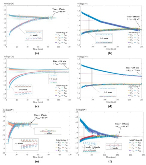
Figure 15.
Experimental voltage trajectories of different equalizers with initial voltage #1 and #2. (a,b) DC2C equalizer based on LCSRC. (c,d) MC2MC equalizer based on HBLCC. (e,f) Proposed MC2MC equalizer based on BRLCC.
5. Discussion
To systematically evaluate the proposed equalizer, Table 4 and Table 5 compares it with conventional equalizers in terms of topology, component, cost, balancing speed (P1), balancing efficiency (P2), soft switching (P3), implementation complexity (P4), and the reliability (P5). Table 4 presents the expressions of needed components for n cells/modules, and Table 5 gives a comprehensive comparison under the assumption that the battery pack has 96 series connected cells and is divided into 12 battery modules [23]. Each module-level equalizer manages eight cells, and the pack-level equalizer manages twelve modules. We can take the proposed equalizer as an example: each module-level BRLCC equalizer needs 4 × (8 + 1) = 36 MSs, and the pack-level BRLCC equalizer needs 4 × (12 + 1) = 52 MSs, so the total number is 36 × 12 + 52 = 484. The component prices per unit is approximated as: MS (MOSFET) ($0.2), DR (MOSFET Driver IC) ($0.8), L (Inductor) ($0.6), C (Capacitor) ($0.2), D (Diode) ($0.15) [33].
Table 4.
Component comparison of equalizers for n cells/modules.
Table 5.
Systematic comparison example for a 96 cells battery pack composed of 12 modules.
5.1. AC2C Equalizer
The AC2C resonant switched capacitor converter (RSCC) based method in [24] can realizes automatic equalization with only a pair of complementary control signals, which means an excellent reliability. It also works with ZCS and thus avoids the EMI, which can be easily picked up by the long wires in the BMS and affects the stable operation of analog-to-digital converter (ADC) and serial peripheral interface (SPI) of the BMS front-end ICs [41]. However, its balancing speed is strongly affected by the parasitic resistance RS, the voltage gap of VBS − VBT according to (22), and the distance between the source cell to the weak cell. Its balancing efficiency is determined as VBS/VBT according to (21), which can be low if the voltage gap is large.
The AC2C three-resonant-state switched capacitor converter (TRSCC) based method in [25] uses an additional resonant path to increase the balancing speed at small voltage gap and improves the balancing efficiency at large voltage gap. However, during the extra release state when the resonant LC tank is short-circuited, no energy is transmitted from the source cell or to the target cell. In other words, the cells have to wait for the release state so that the average balancing current is reduced. Its total efficiency drops exponentially when the source cell is far away from the target cell. Besides, automatic equalization cannot be realized in this method, so the reliability is reduced.
The AC2C automatic buck-boost converter based method in [26] uses coupled inductor (CI) to realize flux compensation, which greatly increases the current capabilities and reduces the need of magnetic coil and filter capacitance. However, the balancing efficiency will still be low if the energy has to be transferred through multiple cells. Unlike the RSCC or TRSCC method, it needs a precise 0.5 duty cycle to realize automatic equalization and has high frequency oscillation in current waveforms that may cause unexpected EMI and reduce the overall reliability of the BMS.
5.2. DC2C Equalizer
The DC2C LC series resonant circuit (LCSRC) based method in [28] uses a LC resonant tank, a cell access network and a bridge network to directly transfer the energy from the source cell to the target cell. It overcomes the problem of low speed at small voltage gap in RSCC, the low average balancing current of TRSCC, and the hard-switching problem of buck-boost converter. It also has fewer DRs because the two MOSFETs in a bidirectional switch can share a driver IC. However, there are 8 MOSFETs in the resonant loop, which increases the parasite resistance Rs and reduces the balancing efficiency. It also requires complex initializing circuit for the gate driver in the bridge network, and the reliability is moderate.
5.3. MC2MC Equalizer
The MC2MC half bridge LC converter (HBLCC) based method in [23] introduces the concept of MC2MC control, which can directly transfer the energy from consecutive strong cells to consecutive weak cells and greatly accelerates the balancing speed in some voltage distributions. However, as analyzed in this paper, the step-up operation modes cannot be realized, and there is a dilemma between balancing efficiency and power as shown in Figure 9.
The proposed bipolar-resonant LC converter (BRLCC) based equalizer uses a LC resonant tank along with a symmetrical switch matrix to realize MC2MC control. It not only solves the high Rs problem of the LCSRC equalizer, but also supports more MC2MC operation modes than the HBLCC equalizer and guarantees a higher and more stable balancing power without seriously sacrificing the balancing efficiency. Since ZCS is maintained, its size and EMI can be reduced. Overall, as an extension of the works in [23,24,25,28], the proposed equalizer offers excellent balancing speed and good efficiency with moderate cost, control complexity and reliability.
6. Conclusions
In order to improve the active equalizers’ balancing speed and efficiency to face new challenge brought by retired batteries, this paper proposes a novel BRLCC for the MC2MC topology. The BRLCC uses the bipolar resonance of the LC resonant tank to deliver energy and overcomes three main problems of existing SCC and HBLCC. The circuit structure, operation principle, mathematical model and comparison are presented to show the following enhancements on MC2MC topology.
- (1)
- Step-up MC2MC operation modes like 1–2, 1–3, 2–3 modes are realized with good efficiency.
- (2)
- Step-down modes like 2–1, 3–1, 3–2 modes can have higher efficiency.
- (3)
- Stable balancing power is guaranteed at small voltage gap.
The simulation comparisons show that, the balancing speed of the proposed BRLCC equalizer is about 30 times of the QRSCC equalizer and 5 times of the HBLCC equalizer. This huge improvement is achieved by only sacrificing about 5–8% of efficiency, and the total efficiency is still maintained at a high level of over than 86%. Compared to the LCSRC equalizer, the BRLCC equalizer almost doubled the balancing speed without sacrificing the efficiency. This is because the BRLCC has four less MOSFETs in the resonant loop.
An experimental prototype for 8 lithium-ion battery cells has also been tested at 9 kinds of operation modes with balancing powers from 1.426 W to 12.559 W and balancing efficiencies from 84.84% to 91.68%. The experimental comparison verifies the feasibility and fast speed of the proposed equalizer, showing it is much faster than the HBLCC equalizer, and is about 60–80% faster than the LCSRC equalizer.
Systematical comparison with typical equalizers also shows that the BRLCC only need moderate components, cost, and has moderate control complexity and reliability. It also inherits the merits of ZCS and low EMI from the resonant converter.
Overall, this paper focus on improving the balancing speed without much sacrificing the efficiency, and the proposed equalizer has achieved huge improvement in this aspect. Therefore, it is suitable for equalizing batteries with serious inconsistency, such as the retired batteries. If a very high reliability is required, the proposed equalizer can cooperate with a reliable passive equalizer to ensure reliable operation. If higher efficiency is needed, the equalizer also allows designer to smoothly adjust the balancing power and efficiency by selecting different Zr in the circuit design.
Author Contributions
Conceptualization, X.L.; data curation, X.L., C.L., H.L.; formal analysis, X.L.; funding acquisition, L.K.; project administration, J.L.; software, B.H.; supervision, L.K.; validation, X.L.; writing—original draft, X.L.; writing—review and editing, C.L. and H.L. All authors have read and agreed to the published version of the manuscript.
Funding
This research was funded by Key-Area Research and Development Program of Guangdong Province, grant number 2019B090911001.
Conflicts of Interest
The authors declare no conflict of interest.
References
- Gao, M.; Qu, J.; Lan, H.; Wu, Q.; Lin, H.; Dong, Z.; Zhang, W. An Active and Passive Hybrid Battery Equalization Strategy Used in Group and between Groups. Electronics 2020, 9, 1744. [Google Scholar] [CrossRef]
- Lee, S.; Choi, Y.; Kang, B. Active Charge Equalizer of Li-Ion Battery Cells Using Double Energy Carriers. Energies 2019, 12, 2290. [Google Scholar] [CrossRef]
- Lu, C.; Kang, L.; Luo, X.; Linghu, J.; Lin, H. A Novel Lithium Battery Equalization Circuit with Any Number of Inductors. Energies 2019, 12, 4764. [Google Scholar] [CrossRef]
- Wang, S.; Kang, L.; Guo, X.; Wang, Z.; Liu, M. A Novel Layered Bidirectional Equalizer Based on a Buck-Boost Converter for Series-Connected Battery Strings. Energies 2017, 10, 1011. [Google Scholar] [CrossRef]
- Gallardo-Lozano, J.; Romero-Cadaval, E.; Milanes-Montero, M.I.; Guerrero-Martinez, M.A. Battery equalization active methods. J. Power Sources 2014, 246, 934–949. [Google Scholar] [CrossRef]
- Farzan Moghaddam, A.; Van den Bossche, A. An Efficient Equalizing Method for Lithium-Ion Batteries Based on Coupled Inductor Balancing. Electronics 2019, 8, 136. [Google Scholar] [CrossRef]
- Uno, M.; Tanaka, K. Double-Switch Single-Transformer Cell Voltage Equalizer Using a Half-Bridge Inverter and a Voltage Multiplier for Series-Connected Supercapacitors. IEEE Trans. Veh. Technol. 2012, 61, 3920–3930. [Google Scholar] [CrossRef]
- Li, Y.; Han, Y. A Module-Integrated Distributed Battery Energy Storage and Management System. IEEE Trans. Power Electron. 2016, 31, 8260–8270. [Google Scholar] [CrossRef]
- Xing, Y.; Ma, E.W.M.; Tsui, K.L.; Pecht, M. Battery Management Systems in Electric and Hybrid Vehicles. Energies 2011, 4, 1840–1857. [Google Scholar] [CrossRef]
- Uno, M.; Ueno, T.; Yoshino, K. Cell Voltage Equalizer Using a Selective Voltage Multiplier with a Reduced Selection Switch Count for Series-Connected Energy Storage Cells. Electronics 2019, 8, 1303. [Google Scholar] [CrossRef]
- Das, U.K.; Shrivastava, P.; Tey, K.S.; Bin Idris, M.Y.I.; Mekhilef, S.; Jamei, E.; Seyedmahmoudian, M.; Stojcevski, A. Advancement of lithium-ion battery cells voltage equalization techniques: A review. Renew. Sustain. Energy Rev. 2020, 134, 110227. [Google Scholar] [CrossRef]
- Zhong, L.; Zhang, C.; He, Y.; Chen, Z. A method for the estimation of the battery pack state of charge based on in-pack cells uniformity analysis. Appl. Energy 2014, 113, 558–564. [Google Scholar] [CrossRef]
- Guo, X.; Kang, L.; Huang, Z.; Yao, Y.; Yang, H. Research on a Novel Power Inductor-Based Bidirectional Lossless Equalization Circuit for Series-Connected Battery Packs. Energies 2015, 8, 5555–5576. [Google Scholar] [CrossRef]
- Pham, V.; Duong, V.; Choi, W. A Low Cost and Fast Cell-to-Cell Balancing Circuit for Lithium-Ion Battery Strings. Electronics 2020, 9, 248. [Google Scholar] [CrossRef]
- Lelie, M.; Braun, T.; Knips, M.; Nordmann, H.; Ringbeck, F.; Zappen, H.; Sauer, D. Battery Management System Hardware Concepts: An Overview. Appl. Sci. 2018, 8, 534. [Google Scholar] [CrossRef]
- Linghu, J.; Kang, L.; Liu, M.; Luo, X.; Feng, Y.; Lu, C. Estimation for state-of-charge of lithium-ion battery based on an adaptive high-degree cubature Kalman filter. Energy 2019, 189, 116204. [Google Scholar] [CrossRef]
- Ye, Y.; Cheng, K.W.E. Analysis and Design of Zero-Current Switching Switched-Capacitor Cell Balancing Circuit for Series-Connected Battery/Supercapacitor. IEEE Trans. Veh. Technol. 2018, 67, 948–955. [Google Scholar] [CrossRef]
- Shang, Y.; Zhang, C.; Cui, N.; Guerrero, J.M. A Cell-to-Cell Battery Equalizer with Zero-Current Switching and Zero-Voltage Gap Based on Quasi-Resonant LC Converter and Boost Converter. IEEE Trans. Power Electron. 2015, 30, 3731–3747. [Google Scholar] [CrossRef]
- Lai, X.; Jiang, C.; Zheng, Y.; Gao, H.; Huang, P.; Zhou, L. A Novel Composite Equalizer Based on an Additional Cell for Series-Connected Lithium-Ion Cells. Electronics 2018, 7, 366. [Google Scholar] [CrossRef]
- Jiang, Y.; Jiang, J.; Zhang, C.; Zhang, W.; Gao, Y.; Guo, Q. Recognition of battery aging variations for LiFePO4 batteries in 2nd use applications combining incremental capacity analysis and statistical approaches. J. Power Sources 2017, 360, 180–188. [Google Scholar] [CrossRef]
- Lee, H.; Park, J.; Kim, J. Incremental Capacity Curve Peak Points-Based Regression Analysis for the State-of-Health Prediction of a Retired LiNiCoAlO2 Series/Parallel Configured Battery Pack. Electronics 2019, 8, 1118. [Google Scholar] [CrossRef]
- Lai, X.; Qiao, D.; Zheng, Y.; Ouyang, M.; Han, X.; Zhou, L. A rapid screening and regrouping approach based on neural networks for large-scale retired lithium-ion cells in second-use applications. J. Clean. Prod. 2019, 213, 776–791. [Google Scholar] [CrossRef]
- Shang, Y.; Zhang, Q.; Cui, N.; Duan, B.; Zhou, Z.; Zhang, C. Multicell-to-Multicell Equalizers Based on Matrix and Half-Bridge LC Converters for Series-Connected Battery Strings. IEEE J. Emerg. Sel. Top. Power Electron. 2020, 8, 1755–1766. [Google Scholar] [CrossRef]
- Ye, Y.; Cheng, K.W.E.; Yeung, Y.P.B. Zero-Current Switching Switched-Capacitor Zero-Voltage-Gap Automatic Equalization System for Series Battery String. IEEE Trans. Power Electron. 2012, 27, 3234–3242. [Google Scholar]
- Shang, Y.; Zhang, Q.; Cui, N.; Zhang, C. A Cell-to-Cell Equalizer Based on Three-Resonant-State Switched-Capacitor Converters for Series-Connected Battery Strings. Energies 2017, 10, 206. [Google Scholar] [CrossRef]
- Phung, T.H.; Collet, A.; Crebier, J. An Optimized Topology for Next-to-Next Balancing of Series-Connected Lithium-ion Cells. IEEE Trans. Power Electron. 2014, 29, 4603–4613. [Google Scholar] [CrossRef]
- Yarlagadda, S.; Hartley, T.T.; Husain, I. A Battery Management System Using an Active Charge Equalization Technique Based on a DC/DC Converter Topology. IEEE Trans. Ind. Appl. 2013, 49, 2720–2729. [Google Scholar] [CrossRef]
- Lee, K.; Chung, Y.; Sung, C.; Kang, B. Active Cell Balancing of Li-Ion Batteries Using LC Series Resonant Circuit. IEEE Trans. Ind. Electron. 2015, 62, 5491–5501. [Google Scholar] [CrossRef]
- Lee, S.; Lee, K.; Choi, Y.; Kang, B. Modularized Design of Active Charge Equalizer for Li-Ion Battery Pack. IEEE Trans. Ind. Electron. 2018, 65, 8697–8706. [Google Scholar] [CrossRef]
- Chen, Y.; Liu, X.; Cui, Y.; Zou, J.; Yang, S. A Multi-winding Transformer Cell-to-Cell Active Equalization Method for Lithium-Ion Batteries with Reduced Number of Driving Circuits. IEEE Trans. Power Electron. 2015, 31, 4916–4929. [Google Scholar] [CrossRef]
- Baronti, F.; Roncella, R.; Saletti, R. Performance comparison of active balancing techniques for lithium-ion batteries. J. Power Sources 2014, 267, 603–609. [Google Scholar] [CrossRef]
- Einhorn, M.; Guertlschmid, W.; Blochberger, T.; Kumpusch, R.; Permann, R.; Conte, F.V.; Kral, C.; Fleig, J. A Current Equalization Method for Serially Connected Battery Cells Using a Single Power Converter for Each Cell. IEEE Trans. Veh. Technol. 2011, 60, 4227–4237. [Google Scholar] [CrossRef]
- Imtiaz, A.M.; Khan, F.H. “Time Shared Flyback Converter” Based Regenerative Cell Balancing Technique for Series Connected Li-Ion Battery Strings. IEEE Trans. Power Electron. 2013, 28, 5960–5975. [Google Scholar] [CrossRef]
- Kim, C.; Kim, M.; Moon, G. A Modularized Charge Equalizer Using a Battery Monitoring IC for Series-Connected Li-Ion Battery Strings in Electric Vehicles. IEEE Trans. Power Electron. 2013, 28, 3779–3787. [Google Scholar] [CrossRef]
- Lim, C.; Lee, K.; Ku, N.; Hyun, D.; Kim, R. A Modularized Equalization Method Based on Magnetizing Energy for a Series-Connected Lithium-Ion Battery String. IEEE Trans. Power Electron. 2014, 29, 1791–1799. [Google Scholar] [CrossRef]
- Hsieh, Y.; Liang, T.; Chen, S.O.; Horng, W.; Chung, Y. A Novel High-Efficiency Compact-Size Low-Cost Balancing Method for Series-Connected Battery Applications. IEEE Trans. Power Electron. 2013, 28, 5927–5939. [Google Scholar] [CrossRef]
- Uno, M.; Kukita, A. Double-Switch Equalizer Using Parallel- or Series-Parallel-Resonant Inverter and Voltage Multiplier for Series-Connected Supercapacitors. IEEE Trans. Power Electron. 2014, 29, 812–828. [Google Scholar] [CrossRef]
- Arias, M.; Sebastian, J.; Hernando, M.M.; Viscarret, U.; Gil, I. Practical Application of the Wave-Trap Concept in Battery-Cell Equalizers. IEEE Trans. Power Electron. 2015, 30, 5616–5631. [Google Scholar] [CrossRef]
- Ye, Y.; Eric Cheng, K.W.; Liu, J.; Xu, C. A Family of Dual-Phase-Combined Zero-Current Switching Switched-Capacitor Converters. IEEE Trans. Power Electron. 2014, 29, 4209–4218. [Google Scholar] [CrossRef]
- Cervera, A.; Peretz, M.M.; Ben-Yaakov, S. A Generic and Unified Global-Gyrator Model of Switched-Resonator Converters. IEEE Trans. Power Electron. 2017, 32, 8945–8952. [Google Scholar] [CrossRef]
- Aiello, O. Electromagnetic Susceptibility of Battery Management Systems’ ICs for Electric Vehicles: Experimental Study. Electronics 2020, 9, 510. [Google Scholar] [CrossRef]
Publisher’s Note: MDPI stays neutral with regard to jurisdictional claims in published maps and institutional affiliations. |
© 2021 by the authors. Licensee MDPI, Basel, Switzerland. This article is an open access article distributed under the terms and conditions of the Creative Commons Attribution (CC BY) license (http://creativecommons.org/licenses/by/4.0/).