1. Introduction
The shift from single core to multi-processor systems-on-chip (MPSoCs) [
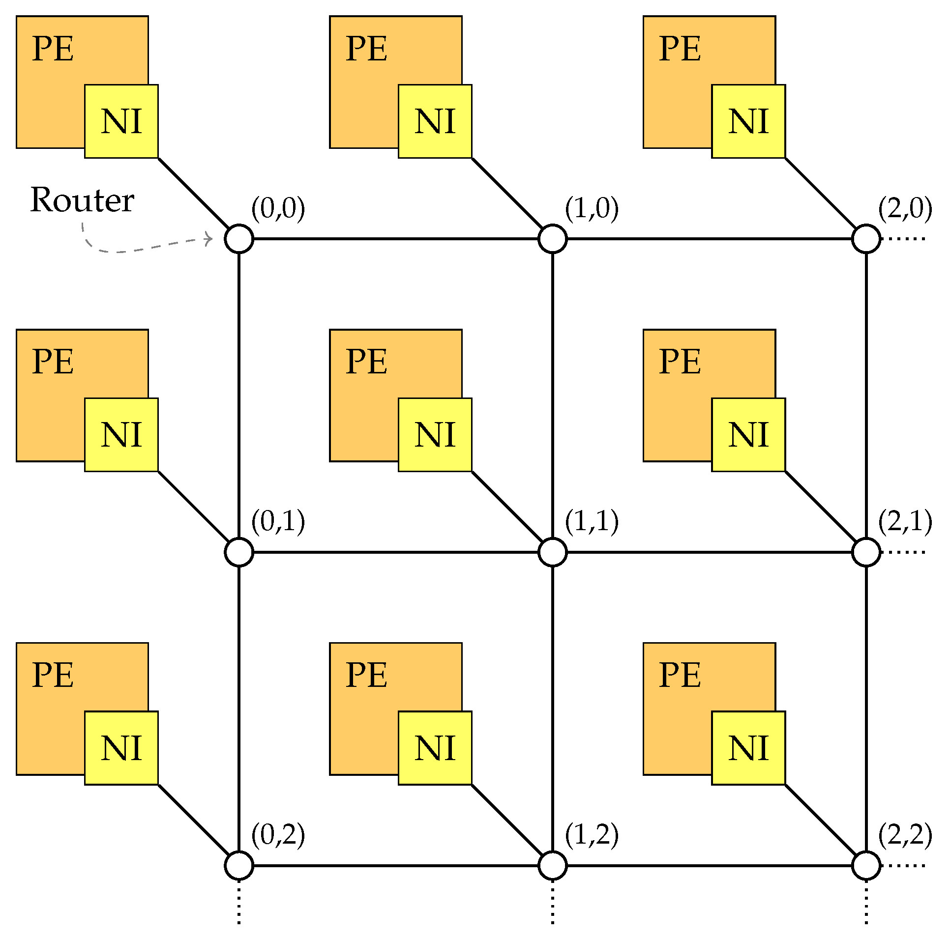
1] has facilitated a massive increase in performance while keeping the power consumption within limits. Since MPSoCs can consist of thousands of cores, it is of utmost importance to provide a scalable and efficient communication medium for them. Here, classical bus-based systems are increasingly being replaced by systems based on packet-switched Networks-on-Chip (NoC) as a solution to the interconnection problem [
2,
3,
4].
The growing complexity of the systems implies a higher susceptibility to errors [
5]. This increased complexity is also reflected in the respective supply chain: own implementation of such design processes as well as owning the respective factories is associated with immense costs [
6]. Hence, due to complexity and costs, MPSoC design and production processes increasingly rely on the integration of third-party components, potentially also from untrusted sources [
7]. Even tools used for design and development may be compromised, and hence pose a tangible threat to MPSoCs [
8]. Such threats can be realized by inserting hardware Trojans (HT), as reported, e.g., in [
7,
9,
10,
11,
12]. When designing NoCs it thus becomes increasingly important to consider not only the resilience against errors but the systems security as well. Although different methods for HT detection have been proposed, the general presence of an HT can never be excluded [
6]. Hence, system designs have to be Trojan-tolerant, i.e., the system itself works even if an HT is present [
6].
NoCs are an attractive target for attackers due to their basic functionality: By design, the MPSoCs’ entire data exchange passes through the NoC, hence, an attacker has the maximum possibilities of intervention at this point [
13]. Purely passive HTs which act as eavesdroppers and aim to exfiltrate confidential data over local or remote channels can be countered by using end-to-end encryption of data. Active attackers, on the other hand, who additionally modify or discard data, are much harder to deal with. Even if the modifications or losses of flow control units (flits) are detected, the respective retransmissions significantly increase the network load and thereby reduce the performance or even basic functionality.
In this work, we present protocols, which ensure integrity and increase availability in NoCs, even in the presence of HTs in routers [
14]. For this, we combine the features of network coding [
15] with cryptographic authentication schemes. The authentication schemes relying on lightweight message authentication codes ensure that flit modifications are detected and handled accordingly. Since message authentication codes are symmetric cryptographic primitives, they require a shared secret between the communicating nodes—this key exchange is out of the scope of this work, but could be realized by pre-sharing keys during an initiation phase. Additionally, network coding measures create robustness against the dropping of flits by HTs and also against the discarding of modified flits, which in combination effectively reduces retransmissions.
We evaluate our proposed schemes with cycle-accurate simulations under realistic traffic assumptions as well as with an analytical model. The results demonstrate that our schemes can ensure a secure data transmission in the presence of active attackers by reducing the respective error probability by up to at a very reasonable overhead. Finally, we analyze to area overhead inflicted by the newly proposed schemes and show that only a area increase is needed in comparison to a state-of-the-art MPSoC.
In summary, we make the following contributions in this paper:
- (1)
we propose protocols providing integrity protection and availability enhancement for NoC communications,
- (2)
we subsequently evaluate the performance of these protocols extensive simulations,
- (3)
we develop an analytical model for faster and more flexible evaluation,
- (4)
finally, we analyze our solutions in terms of additional chip area required.
The remaining work is organized as described below: The state of the art regarding NoC security and HTs is laid out in
Section 2.
Section 3 describes our system model and the respective assumptions. In
Section 4, we propose our solution for integrity protection. We then present our analytical model for further analysis of the proposed security solutions in
Section 5. Here, we also detail the results of this model accompanied by the respective simulation results and a discussion of the inflicted area overhead. Finally,
Section 6 summarizes the paper and describes possible further research questions.
2. Related Work and State of the Art
One of the main attack angles against MPSoCs is the embedding of HTs into them, e.g., [
6,
13,
16,
17]. HTs are covert autonomous functional units directly incorporated by attackers into the hardware of the attacked system. Due to the physical hardware integration, HTs have direct access to all processed data at the lowest level. This allows them to arbitrarily read, possibly exfiltrate, modify or discard data [
6]. Their ability to execute arbitrary attacks, especially in the domain of internal communications, demands effective countermeasures [
13]. A presentation of significant work in this area is given in the following.
Ancajas et al. [
10] were the first to present the threat potential of HTs in NoCs and presented initial solutions on how to diminish such threats. These solutions include measures such as scrambling the data at the lowest layer, certifying individual transmitted packets, and a process migration scheme, which serves to obfuscate the respective target application [
10]. These measures are primarily intended to prevent data interception by a malicious NoC by complicating the tracing of logical data streams. Additionally, these schemes intend to prevent the initial triggering of an HT. A similar strategy is followed by the solution of Setumadhaven et al. [
7], where the triggering events of HTs are also inhibited. Despite the effectiveness of these measures, they involve considerable computational effort and thus significantly degrade the performance of the system.
Another approach to minimizing the risks posed by HTs is to detect and remove them at runtime. Frey and Yu [
18] proposed a system based on a finite state machine, which represents the possible execution paths for the single MPSoC components. If a component deviates from the set of valid execution paths, it is assumed to be compromised and accordingly, this component is disabled. Since the finite state machine must represent the respective executions in real time and store the individual states of all monitored components, this system comes with a non-negligible computational and memory overhead. The authors proposed a more lightweight solution for the detection of HTs that alter flits and their attached meta-data, e.g., routing information [
18]. Since this system operates within the NoCs routers, an additional overhead for each router and in turn a reduced NoC performance is implied.
A fundamentally different approach is to prevent HTs from being embedded in the system up front [
7,
19]. For this purpose, different systems have been proposed that verify the design procedure of outsourced production processes by performing static backdoor analysis during the complete design and production phases. Alternatively, the entire design process is changed to security orientated development procedures.
However, HTs are an attack vector that cannot be mitigated completely [
6]. Therefore, other strategies aim to diminish the exposed risk by securing the communication during attacks. Following the classification in [
6], such solutions are Trojan-tolerant, as they provide the functionality even in the presence of an active HT. Notable works include the solution by Boraten and Kodi [
12], who propose the use of algebraic manipulation detection codes for the identification of flit modifications. The authors claim a minimal performance impact of 1% compared to NoCs. No evaluation with respect to security is presented. Alternatively, Kapoor et al. proposed to protect the communication using authenticated encryption [
20]. However, the chosen cryptographic primitive, AES-128 in GCM mode, is heavy-weight regarding efficiency and area overhead and, therefore, it is an infeasible solution for NoCs [
9].
For a comprehensive presentation of the state-of-the-art regarding HTs and the protection against them, we would like to refer the reader to surveys like those by Rajesh et al. [
13], which details the threats and attack vectors exposed through HTs, Xiao et al. [
6], presenting a classification for HTs itself as well as for the respective countermeasures and, finally, Shakya et al. [
8], describing HT deployment strategies and their detectability.
In summary, of the classic security objectives, confidentiality, integrity, and availability, the presented works usually consider only the first two. If all three are considered, the efficiency and chip area are neglected instead. In this work, we consider both integrity and availability, taking both under the special circumstances of high latency requirements and limited area. Additionally, our solution is completely independent of the actual application and thus can be used widely.
4. Concept for Communication Protection
4.1. Possible Approaches
Losses of flits will be detected using timers (details are given in the following sections). The common measure to achieve integrity is authentication through a symmetric or asymmetric cryptographic system. By both approaches, an authentication tag is computed that is used to verify the integrity of the message: a digital signature in the case of asymmetric authentication or a message authentication code in the case of symmetric authentication. Digital signatures are not suited for authentication of flits since they are too long to be included within a flit. Furthermore, their computation requires a high computational effort. Under the consideration of these drawbacks, we decided to use symmetric authentication schemes for the computation of the tags. The necessary key exchange is out of the scope of this paper. One possibility is to exchange keys during an initialization phase of the system.
An adequate solution for communication within a NoC has to fulfill the specific demands on delay and area overhead. The Advanced Encryption Standard (AES) is not suited because it requires 1032 cycles per block encryption [
26]. Therefore, a lightweight method that is optimized for implementation in hardware should be chosen as the cryptographic scheme. We selected mCrypton [
27] since that algorithm provides a low delay of only 13 cycles per block and requires an area of 2681 gate equivalents only [
26].
The authentication tag prevents undetected modification of data to be transmitted since the computation of this tag requires the knowledge of the secret key. In addition to the data field, it is also necessary to protect the metadata fields since modifications of these fields can also harm the system. If the receiver detects a modification, he discards the affected flit. In the case of network coding, he might still be able to decode due to the included redundancy. Otherwise or in case of uncoded transmission, the receiver issues an ARQ to initiate the retransmission of the modified flits.
In the case of network coded transmission, tags are computed for the linear combinations. Hence, the receiver can check the validity of combinations after arrival and use only valid ones for decoding. Network coding implies in general the need to use homomorphic authentication schemes. However, since we assume that only the sender computes linear combinations, this is not necessary. To avoid computational overhead for intermediate nodes, the tags are used for an end-to-end authentication, i.e., only the receiver verifies the validity of flits received.
An attacker is not able to undetectably modify flits but he could try to disturb transmission by injecting a valid flit sent by the same sender (replay attack). The FID or GID is an increasing number so that the receiver can recognize the injection of an already received fit. Hence, the FID or GID must not repeat as long as the same key for the computation of the tag is used to prevent a replay attack. A length of 24 bits allows different values for the identifier. Given the payload of 64 bits per flit, a sender can send 128 MiB data using uncoded transmission to the same receiver before the corresponding key needs to be changed. In the case of network coded transmission, the sender can transmit 256 MiB since the two flits of a generation get the same GID. The amount of data that can be exchanged using the same key can be increased by enlarging the FID or GID.
We investigated two different possibilities for authentication:
4.2. S1: Send Data and Tag in Two Separate Flits
In this protocol, the symmetric block cipher mCrypton is directly used to compute the tag. Therefore, CBC-MAC is employed that bases on cipher block chaining (CBC) mode [
28]: Using an initialization vector of zero, the input blocks are encrypted employing CBC, and the last ciphertext block serves as tag. CBC-MAC has security deficiencies for messages of arbitrary length [
29], but in the proposed protocol, the number of input blocks that need to be authenticated is constant.
The block size of the underlying cipher determines the size of the tag. The block size of the chosen cipher mCrypton is 64 bits, hence, it equals the size of the data field. The tag is put into the data field of an additionally generated flit, the so-called tag flit. The mode field indicates the flit type. All other fields of data and tag flit are the same.
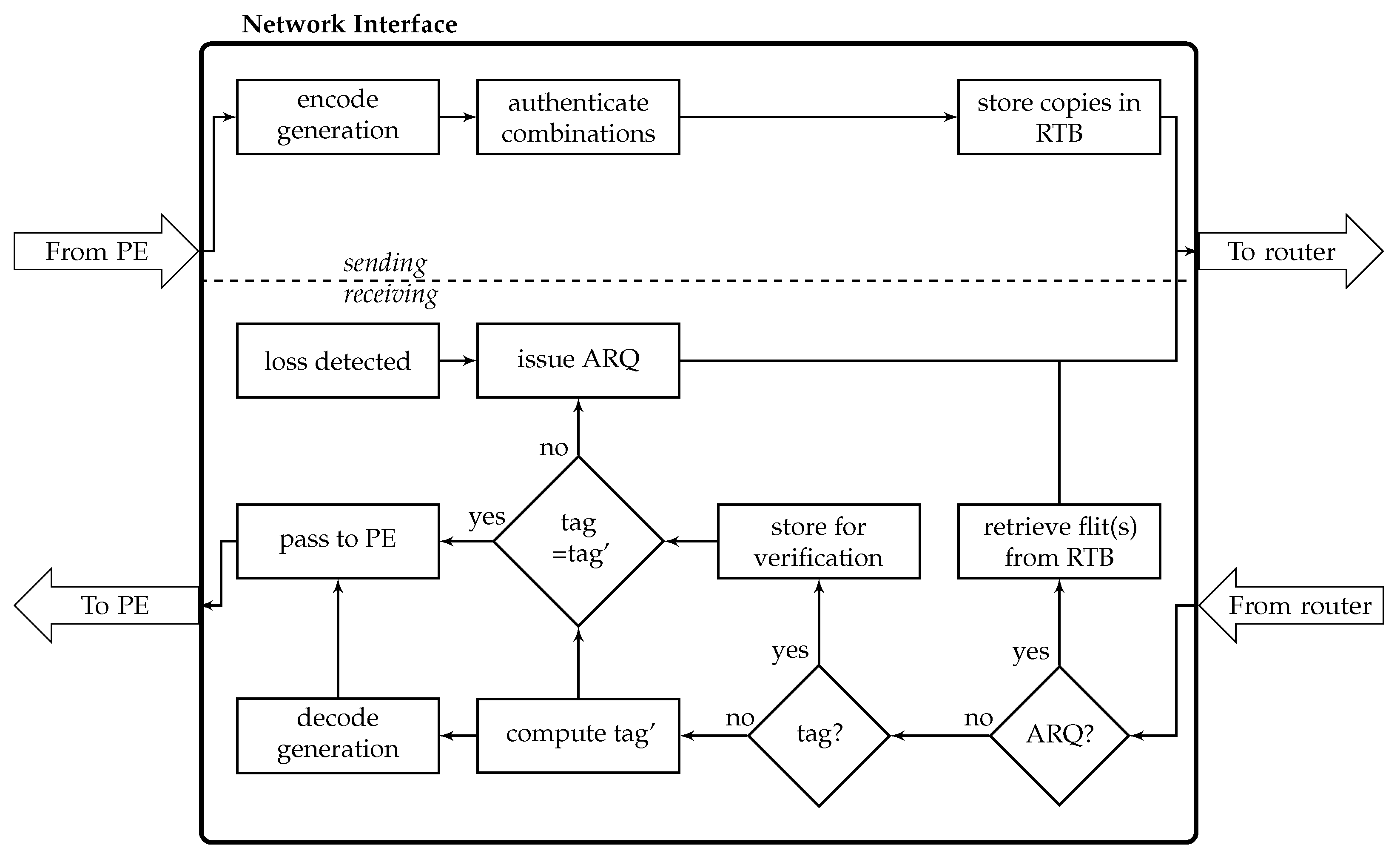
Uncoded transmission (UC): In the case of UC, the sender computes for each original flit delivered by the PE a tag flit. If the computation of the tag is finished, data flit and tag flit are put into the transmission buffer and sent consecutively. Additionally, a copy of both flits is stored in the retransmission buffer so that the tag does not need to be computed again in case of retransmission.
When the receiver gets a data flit, the computation of the tag can immediately start. If the computed tag equals the received tag, verification was successful and the data flit can be delivered to the PE. Otherwise, an ARQ for both data flit and tag flit has to be issued since it is not possible to decide which of them was modified.
The arrival of a flit also triggers the start of a timer at the receiver to allow for the recognition of losses. If there is a time-out, the receiver issues an ARQ. If the receiver gets first a tag flit, it can directly issue an ARQ since the order of flits is not changed during transmission.
Network Coded transmission (NC): When
G original flits arrived at the NI of the sender, the computation of the
C linear combinations starts (
Figure 3). Afterward, the sender computes a tag for each of these combinations, puts the resulting
flits into the transmission buffer, and sends them consecutively. Similar to UC, copies of all flits are stored in the retransmission buffer.
When the receiver gets a data flit (i.e., a linear combination), it starts the computation of the tag. After successful verification of at least G combined flits, decoding starts. Finally, the decoded flits are delivered to the PE. Due to the redundancy, decoding may still be possible even if modifications are detected. For example, if 2 of 4 received combinations failed verification, decoding is possible if the remaining 2 combinations are unmodified. If there are not enough valid combinations, the receiver issues an ARQ for both data and tag flit.
For the recognition of losses, timers are used as described for UC. However, an ARQ is only necessary if not enough valid combinations arrived at the receiver.
Input for the computation of the tag is the whole data flit of 141 bits (UC) or 149 bits (NC). Given the block length of 64 bits, there are three input blocks for mCrypton, the last one padded with zeros. Hence, the computation of the tag implies a delay of
cycles for both sender and receiver. Since the injection rate of flits is much higher, it is necessary to consider a reasonable number of crypto modules for each NI in the NoC so that authentication of different flits can be performed in parallel (
Section 5.5).
Although we consider the transmission of single flits, the protocols imply that more than one flit will be injected into the network. The flits that are needed for a successful transmission form a transmission unit. In the uncoded case, a transmission unit comprises the data flit and tag flit, in the network coded case, it comprises the C linear combinations and the corresponding tag flits.
4.3. S2: Include Data and Tag in One Flit
The advantage of this approach is that the receiver only needs one flit for the verification of integrity. However, if we do not want to increase the flit size, the tag size is a problem. Adding a tag of 64 bits would imply an increase of the flit size by % for UC and by % for NC. Nevertheless, the block size should not be smaller for security reasons.
Therefore, we decided to use an authentication code [
30] as an alternative. As shown in
Table 1, this authentication code requires two randomly selected key bits for the authentication of one message bit. For each message and tag bit, two possible keys remain. Hence, when an attacker wants to modify an intercepted flit, he can only guess with a probability of
the correct key bits for every single bit he wants to change. Authentication of
x message bits requires a stream of
key bits. Thus, 64 key bits can be used for the authentication of 32 message bits. The resulting 32 tag bits can be put together with the 32 data bits in the data field of one flit.
Verification requires the generation of the identical stream of key bits at the receiver side, even if previous flits are lost. Encryption of all fields but the field allows pseudo-randomly generating the necessary key bits.
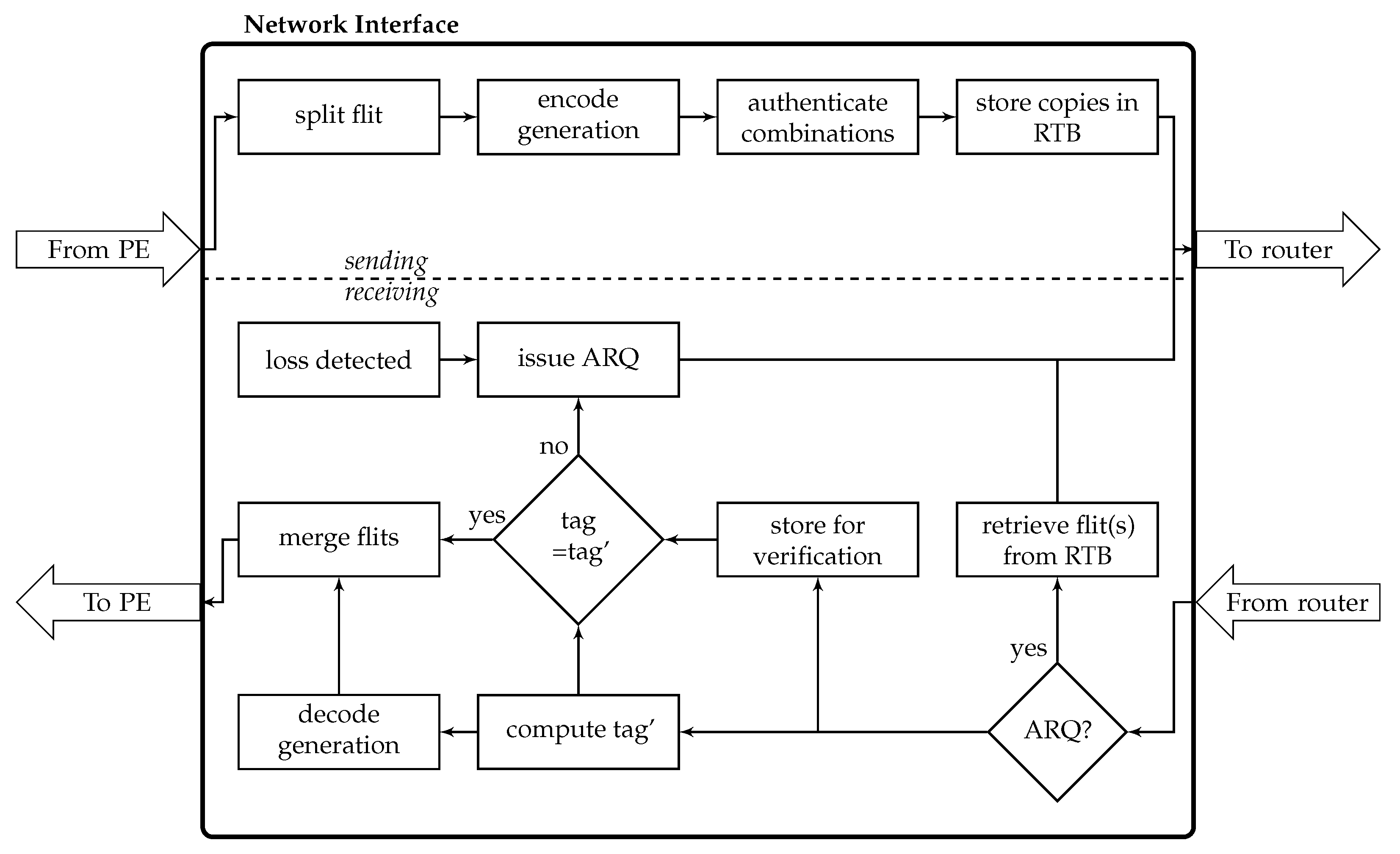
Uncoded transmission: The sender splits each 64-bit data block into two blocks containing only 32 bits. These blocks are distributed to two flits where they are stored as the first half of the data field. The other fields of these flits are equal despite the flit ID that indicates which flits belong together.
For UC, there are 77 bits of metadata that need to be encrypted to generate the 64-bit key for authentication. Hence, there are two input blocks for encryption, the second one padded with zeros. The block cipher is used in CBC mode, and the second ciphertext block serves as the key. The actual computation of the tag bits can be done by a simple look-up in
Table 1 with negligible effort. The authentication bits are stored in the second halves of the corresponding flits. The resulting flits are sent consecutively while a copy of each of them is stored in the retransmission buffer.
After the arrival of a flit, the receiver starts to compute the pseudo-random key, computes the tag bits, and verifies the integrity of the flit by a comparison of received and computed tag bits. Since one data block is divided into two flits, both flits are necessary for successful transmission. If verification of one or both flits failed, the receiver issues an ARQ. However, in contrast to S1, if only one flit was affected, the retransmission of that single flit is sufficient. Equivalently to solution S1, timers are employed for the recognition of losses.
Network Coded transmission: Again, the 64-bit data field is split into two halves that are distributed to two flits. These two flits establish a generation of size
so that the sender can immediately compute the
C linear combinations (
Figure 4).
Since the GEV also belongs to the metadata, the size of the input for the block cipher is 85 bits which also results in two input blocks. The subsequent processing is equivalent to the uncoded case: For each of the two flits, the input blocks are encrypted, the tag bits are computed and stored in the second halves of the data field and the flits are sent.
As in the uncoded case, the receiver starts to compute the pseudo-random key immediately after receiving a flit. For successful decoding, G of the C linear combinations need to arrive successfully at the receiver. If this is the case, the receiver decodes, generates the original 64-bit data block and delivers it to the PE. Otherwise, it issues an ARQ for the retransmission of a single flit.
For both uncoded and network coded transmission, there are two input blocks for the block cipher what requires cycles for the selected algorithm.
For S2, a transmission unit contains the two flits in case of the uncoded transmission and all C linear combinations in case of network coded transmission.
4.4. Security Analysis: Integrity and Availability in Case of Losses and Modifications
The goals of the proposed protocols are to ensure integrity and to increase availability in NoCs in presence of an active attacker who modifies or drops flits. Integrity means that data is correct or that it is unnoticeably not the case. In other words, there must be no undetectable modifications of transmitted data. In the proposed protocols, protection of integrity bases on the use of tags. Given that the cryptographic primitives used are secure, an attacker is not able to compute a valid tag for modified data without knowledge of the symmetric key shared between sender and receiver. Hence, any modification will be detected by the receiver. The attacker may also change address information so that the receiver uses the wrong symmetric key, but of course, this will also result in a failed verification of the tag. Hence, integrity will be guaranteed—modified flits are discarded so that there is no chance for an attacker to influence subsequent processing by injecting falsified data.
The second goal is to increase availability. Of course, availability includes integrity, thus, this protection goal is influenced by both modifications and losses. Three requirements need to be fulfilled in order to ensure that flits sent are available at the receiver: (R1) The receiver must be able to detect losses and modifications, (R2) the receiver must be able to issue useful ARQs (an ARQ is useful if it triggers the retransmission of the needed flit(s)), and (R3) the retransmission must be successful.
Of course, it is not possible to enforce availability if there is an attacker that is able to massively disturb the system so that at least one of these requirements cannot be met. However, this is a general limitation and not specific for the protocols proposed in this paper. Under the assumption that the attacker tries to hide his activities, there will be a limited number of losses and modifications. In this case, the suggested protocols still allow transmiting data.
Availability in case of losses: Losses will be recognized by means of timers (R1). The receiver always starts a timer after the arrival of a flit, in case of a timeout, an ARQ is issued. A special case is the loss of the first flit of a transmission unit, but this will be detected as well:
S1 UC: The receiver will immediately recognize this loss. Since the order of flits is not changed during transmission, the arrival of a tag flit indicates the loss of the corresponding data flit.
S1 NC: The same applies here, the arrival of a tag flit indicates the loss of the corresponding linear combination. If both data and tag flit are dropped, decoding may still be possible due to the included redundancy, otherwise, an ARQ will be issued.
S2 UC: The flit identifier of the second flit indicates the loss of the first flit.
S2 NC: Detection of loss is not possible in this case; but equivalently to S1 NC, either the redundancy is sufficient or an ARQ is triggered by the timer.
Hence, losses will be detected given that at least one flit of a transmission unit arrives at the receiver.
If there is only loss, the receiver is always able to specify the flit to be retransmitted, i.e., to send a useful ARQ. In S2 NC, the receiver cannot directly specify the lost flit; however, the flits already received. A limitation of the second requirement (R2) is given by the need to limit the number of possible ARQs in order to restrict the increase of the network load. However, the number of ARQs per transmission unit is a system parameter that can be set.
The fulfillment of the third requirement (R3) depends on the size of the retransmission buffer (a system parameter that needs to be set accordingly) and the success of the retransmission itself. The selection of another path is suggested to increase the chance to use a path without corrupted routers.
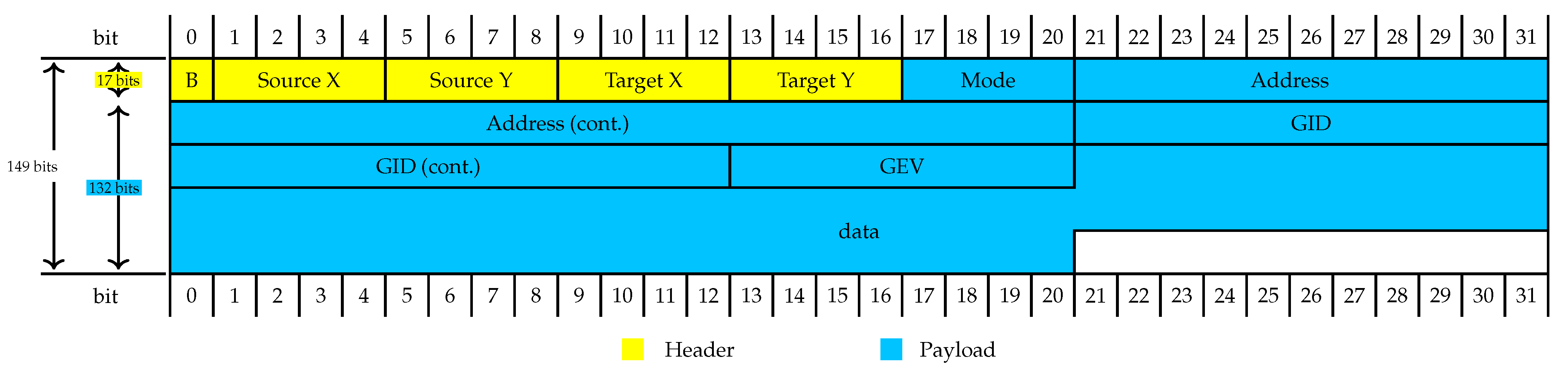
Availability in case of modifications: As stated above, any modification will be detected and the affected flit(s) will be discarded. Hence, availability requires that the receiver is able to issue a useful ARQ if a modification was detected (R2) and that the necessary flit(s) can be successfully retransmitted (R3). The former condition requires a closer examination of modifications of the fields contained in a flit (
Figure 2). We will not discuss the modification of the burst bit since it is not used here. Hence, it is always set to zero.
A modification of the data field that contains the data or the tag is the simplest case since the required flits can be correctly specified in the ARQ. The same applies to the address field. Modifications of the remaining fields need to be further considered; thereby, we assume that at least one flit of a transmission unit is correctly transmitted:
Source address: If the modified source address is not valid for the given topology, there is no possibility to issue an useful ARQ. However, the receiver will recognize the loss of that flit as described above. If the modified source address is valid, the ARQ will be sent to the wrong sender, a retransmission is not possible. However, the arrival of a further flit at the correct recipient will imply the recognition of loss so that an ARQ is issued.
Target address: The incorrect receiver will issue an ARQ; the sender cannot find the requested flit(s) in its retransmission buffer and will discard the ARQ. However, detection of loss by the correct recipient will issue a useful ARQ.
Mode: For S1, the mode can be changed from data to tag and vice versa. This will imply a detection of loss and the retransmission of the modified flit. A change of data or tag mode to ARQ will imply that the receiver tries to select the requested flit from its retransmission buffer what is of course not possible. However, if the other flit, either data or tag, is not modified, a useful ARQ will be triggered due to the recognition of a loss. A change of mode ARQ to data or tag prevents that the intended retransmission is successful; the issued ARQ is not useful.
For S2, there are only two modes, data or ARQ. The implications of changes are similar to S1.
FID/GID: For S1, verification cannot be completed since two corresponding flits are necessary for all communication schemes. A change of the FID or GID implies that the modified flit seems to belong to another transmission unit, hence, the receiver recognizes two lost flits and will issue two ARQs. Examples given, if the FID of the data flit in case of S1/UC is modified, the receiver will issue one ARQ using the modified FID for the tag belonging to the modified data flit and another ARQ using the correct FID for the data flit belonging to the correct tag flit. Only the latter is useful but this is sufficient for a successful transmission.
In case of S2, computation of the tag can start immediately. Basically, the change of the FID or GID also implies that the receiver treats the modified flit as part of another transmission unit and recognizes loss for both received flits. For the correct flit, the receiver will detect loss and issue a useful ARQ. For the modified flit, both loss of the corresponding (but not existing) flit and modification are detected. It depends on the timer for the recognition of loss as well as on the time needed for the computation of the tag what problem is detected first. In both cases, the issued ARQ is not useful but also not necessary for a successful transmission.
GEV: In case of S1, there are always two flits with the same GEV. Hence, a change of the GEV implies the detection of loss in two cases; verification cannot be completed since the receiver does not have two corresponding flits. The second flit of the pair is the tag flit. Since the order of flits is not changed, the arrival of the tag flit with a GEV that was not contained in the data flit received before indicates the loss of a tag flit and a data flit. To enable the sender to select the correct flit for retransmission, we consider to include in the ARQ the GEVs and modes of already received flits.
In case of S2, computation of the tag will immediately start. The redundancy included in NC is sufficient for decoding if only one flit was modified. Nevertheless, it is possible to issue a useful ARQ by including the GEVs of the unmodified flits.
Given a limited number of losses or modifications, data can still be successfully transmitted. If there is only one modification or loss per transmission unit, availability can be guaranteed (a change of the mode field from ARQ to data or tag will not appear in this case). In some cases, unnecessary ARQs are issued what increases the network load, but transmission can be completed due to the recognition of losses. To support the selection of flits from the retransmission buffer, ARQs specify required flits as well as successfully received flits.
5. Performance Evaluation
5.1. Parameters and Performance Metrics
The performance of our proposed authenticated schemes was evaluated by simulation in a cycle-accurate NoC simulator as well as using an analytical model. The specific simulation parameters and their corresponding values used in the investigations are summarized in
Table 2. In all scenarios, the NoC was injected with a total average flit injection rate of
flits/module/cycle for all schemes. Due to the coding and communication schemes, the actual flit injection rate is different from the flit generation rate at the PE so that the latter must be adjusted to ensure an equal injection rate of
flits/module/cycle. In UC, two flits are generated from the original flit (e.g., due to tag generation in S1 or due to data flit halving in S2), so that the flit generation rate at the PE was corrected to 0.1 flits/module/cycle. In the NC schemes, to account for the redundant combinations as well as the tag flit generation, the flit generation rates at the PE were similarly adapted to
and
for G2C3 and G2C4 respectively.
In the evaluations, a limitation of the maximum number of retransmission and ARQs to 1 per logical transmission unit was applied to avoid very high loads that would saturate the network. This limitation also keeps the error control system simple but effective. It was assumed that ARQs can be dropped but not modified and hence ARQs are not authenticated. This assumption is reasonable since a modified ARQ would cause the retransmission of the flits unrelated to the desired logical transmission unit and therefore would have the same effect as if the ARQ had been lost.
The following performance metrics were considered:
Acceptance rate (A): also denoted as the network load, this is given by the total number of flits (including redundant flits due to NC, tag flits, ARQs and retransmissions) injected per node in a clock cycle.
Information rate (I):the ratio of actual data flits transmitted to the total flits transmitted, which includes the redundant flits, tag flits, ARQs, and retransmissions.
Residual error probability ():The proportion of transmitted data flits that failed to reach the destination, due to dropping and modifications, under the assumed limitation of ARQs and retransmission.
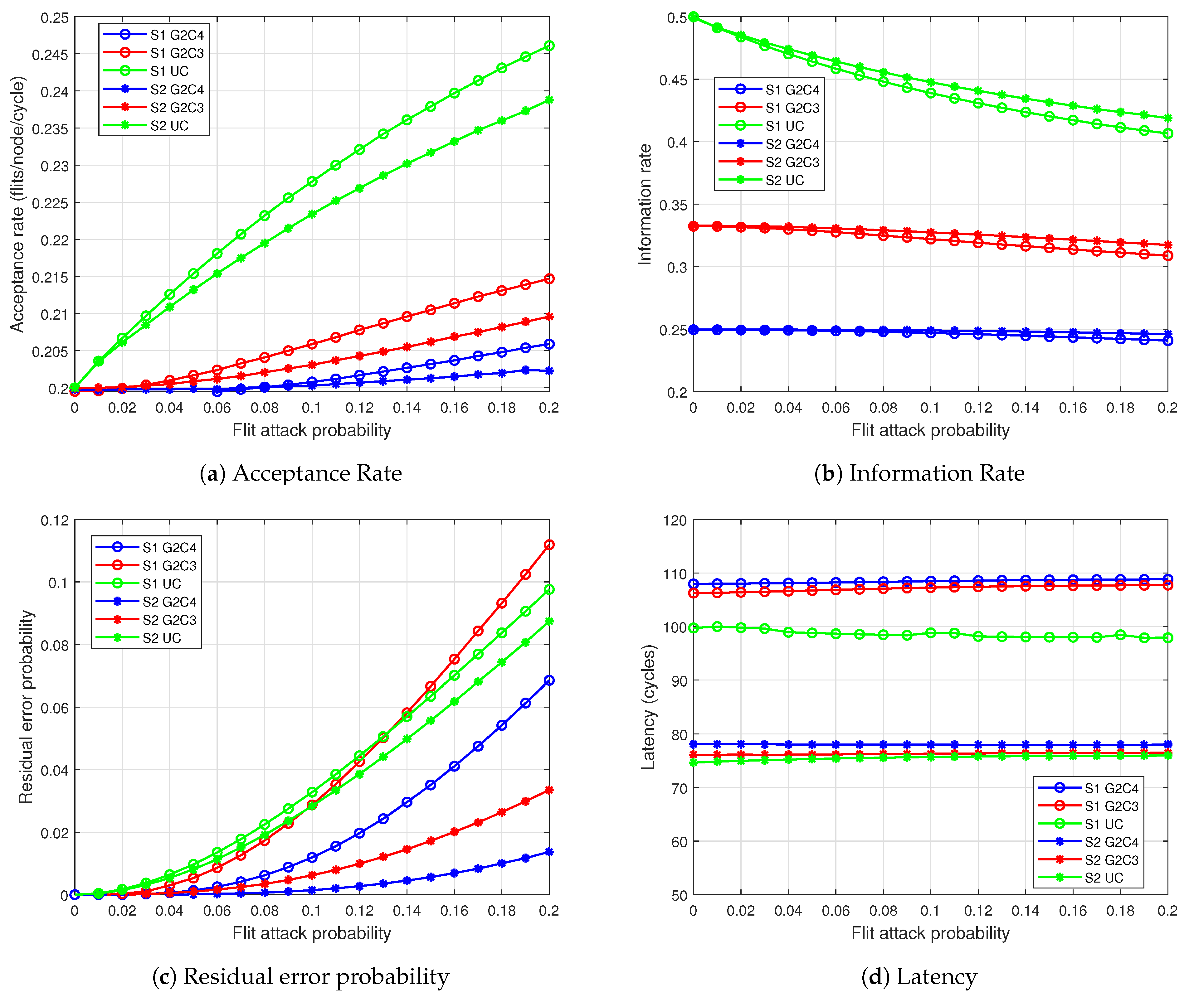
Finally, the metric Latency was evaluated throughout the simulations and within the analytical model, which described the average path latency with respect to the varying and . However, there are some problems with latency results. Due to the rising drop and modification probabilities, there will be more flits lost over the course of the experiments, which finally will lead to the loss of complete transmission units. Since this loss cannot be detected, the overall load in the network will become smaller, which in turn results in lower path latencies, giving the false impression that the performance regarding latency would be better with increasing /. This effect was verified by the simulations as well as the analytical model. Due to this diminished information value, we do not consider the latency throughout the upcoming discussion. Nevertheless, the latency results are presented for the base and analytical model to show the mentioned effects.
5.2. Simulation Scenarios
Simulations were conducted in different overall scenarios. In a single scenario, a key component of the simulation is changed, to inspect the respective impact on the solutions and the key metrics. The following scenarios are considered:
- Base
The base scenario, which uses the simulation parameters as described in
Table 2 and the weights
for the sum
.
- No drops
In this scenario, the attacker does not perform any dropping attacks but solely modification attacks. This means the weighted sum of is calculated with weights and , hence . Therefore, the impact of modifications can be further evaluated.
- No modifications
The same as above but reversed: the rogue routers will not perform modifications, but solely dropping attacks, i.e., , and thereby .
- More attackers
To further investigate the effect of different numbers of attacking nodes, the number of rogue routers will be varied. In this case, the number of attackers will be increased from formerly 8 to here 16.
- Fewer attackers
In this scenario, the number of attacking routers will be decreased to 4.
All parameters not explicitly mentioned will be kept constant in the single scenarios.
5.3. Simulation Results
The proposed authentication schemes were evaluated by cycle-accurate simulations in a C++ simulation framework [
31] extended to include the authentication schemes and NC, including delays implied by network coding and cryptographic primitives.
The different performance parameters were evaluated in response to a varying attack probability . To remove the effect of the locations of the malicious routers within the NoC, the random position of the malicious routers were varied over 1000 iterations and then the obtained results were averaged.
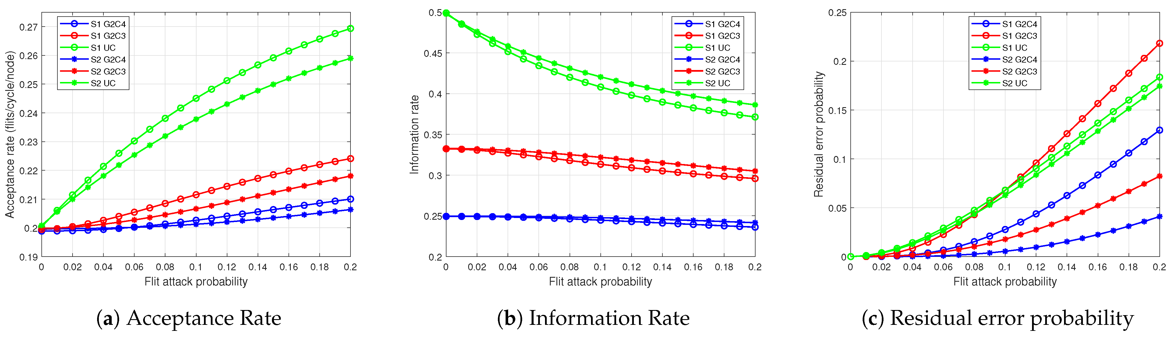
The results of the base simulation scenario are depicted in
Figure 5. The effect on the acceptance rate is shown in
Figure 5a, in which the curves rise from a starting value of
at
attack probability as the ARQs and retransmissions increase to tackle the drops and modifications as the attack probability increases to
. The effect is more severe in the UC scheme in which the lack of redundancy results in ARQ and retransmission for each flit loss or modification. In comparison, NC due to the inherent redundancies requires retransmissions only when the generation could not be completed at the receiver. G2C4 performs better than G2C3 since it has greater redundancy than G2C3. S1 has a lower performance in comparison to S2 since S1 requires greater retransmissions. This is because due to the separate transmission of the data flit and the corresponding tag flit, not only is the susceptibility to attack increased but also because when one of them is modified, both of them must be retransmitted since since the receiver cannot decide which was modified.
Figure 5b depicts the information rate with respect to the attack probability. As the ARQs and retransmissions increase, the total rate of information transmitted is decreased and for the same reasons as mentioned before, S2 performs better than S1.
The residual error probability (
Figure 5c) starts from 0 and increases with increasing attack probability, as fewer logical transmission units are received at the destination. In general, S1 has higher error probabilities, because of its higher attack susceptibility. For the greatest attack probability of
, the lowest error probability of ≈0.014% is achieved by S2/G2C4. The redundancy of the NC schemes displays its advantage over the UC schemes; however, from the curve of S1/G2C3, it can be observed that the redundancy of G2C3 is insufficient at higher error rates to counter the higher attack susceptibility so that the error performance of S1/G2C3 degrades rapidly and becomes worse than UC at attack probabilities
and
for S1 and S2 respectively.
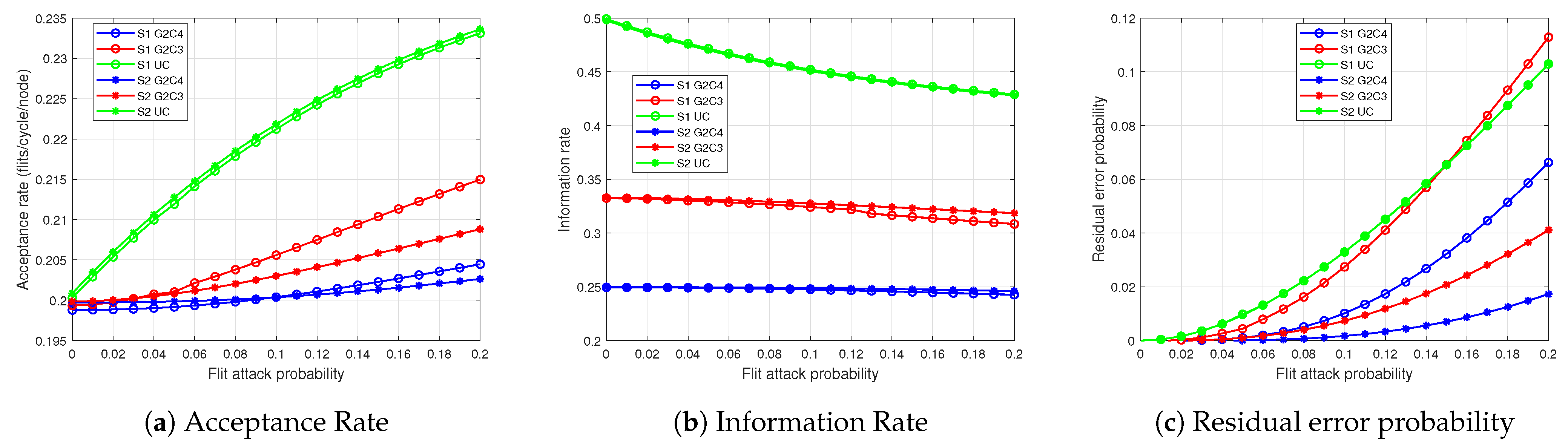
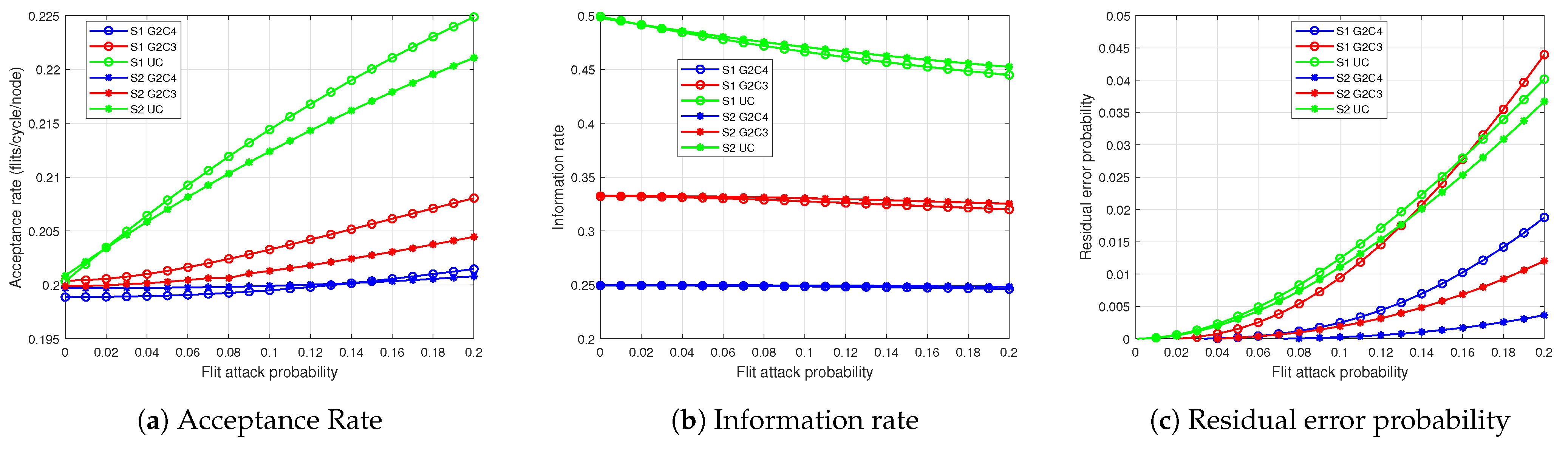
The further simulation scenarios in general supported these results. A complete set of figures depicting the results of these runs can be found in
Appendix A.
The scenario no drops mainly affects the UC cases, whereas the NC solutions mostly deliver the same results as in the base scenario. The most obvious difference is an increased acceptance rate for the UC cases, which are ≈4% higher than in the base scenario. As acceptance and information rate are tightly coupled, the information rate for these cases drop more than in the base scenario.
In the no modifications scenario the most prominent change is that both UC cases now follow the same slope for all metrics. The diagrams also show that the acceptance rate is in general a bit lower for all schemes. The biggest decrease can be observed for S1 UC.
A closer look at the impact of drop and modification delivers an explanation for these results. In case of a drop, only the missed flit needs to be retransmitted. In contrast, a modification always requires to retransmit data and tag, i.e., two flits in case of S1. Consequently, a drop in S1 UC has the same effect as a drop in S2 UC since there is no redundancy. The differences between the NC schemes stem from the different redundancy (differences between G2C3 and G2C4) and from possible cases that may cause a retransmission (differences between S1 and S2). The analytical model provides a deeper insight into the reasons for these differences.
The two scenarios varying the number of attacking routers, more attackers and fewer attackers, have straight forward effects on the metrics: Reducing the number of attackers from 8 to 4 more than halves the residual error probability while the overall shape of the curves is pertained. For of the highest residual error probabilities (S1/UC and S1/G2C3) are reduced from over to ≈0.04 ( resp.). The worst solution in the base scenario (S1/UC) added to the acceptance rate—with 4 attackers only are added, while again pertaining the overall slope. Finally, the same holds for the information rate, where the attackers negative effect is approximately halved.
For more attackers, the effects are comparable: the residual error probability is approximately doubled for all solutions. The acceptance rate is not affected in the same linear way: for , the added impact for S1/UC is not increased by to but solely by to ≈0.07 since we limited the number of ARQs in the simulation runs. Similar results are obtained for the information rate, where the impact is increased by a factor of .
Overall, the extend evaluation with more diverse scenarios validates the results from the base scenario: the network coded approaches are significantly more robust than the uncoded transmission. Among the coded solutions, S2 outperformed S1, especially in terms of residual error probability and acceptance rate.
5.4. Analytical Model
An analytical model gives us a deeper insight into the system behavior so that we can understand how the performance is affected by the different factors. Furthermore, with an analytic model it possible to investigate with greater flexibility different scenarios such as other topologies or various NoC sizes. In contrast to the extremely time-consuming cycle-accurate simulations, the model computes results significantly faster (more than faster for the NoC), allowing investigating the performance of large NoCs that would be impossible to investigate through cycle-accurate simulations.
In the following, we develop analytical expressions of Residual error probability (
), Acceptance rate (A), Information rate (I) and Latency (
ℓ) for S1 and S2. These will be then applied to compute the performance results for the
NoC and compared to that obtained from cycle-accurate simulations. Furthermore, as an application of the analytical model, we use it to determine the system performance of a very large NoC consisting of over a 1000 nodes when using S1 and S2 authentication schemes. The different parameter symbols used in the analytic model are summarized in
Table 3. Certain symbols (such as the drop and modification probabilities,
and
) were already introduced in
Table 2 and is not repeated here.
The total flit drop or the modification probability between two modules are two quantities which are extensively used in the expressions of the performance metrics. This metric depends on the number of attacking routers,
encountered along the XY route between two modules a and b:
5.4.1. S1 Authentication Scheme
In S1 authentication scheme, flits are always transmitted in pairs, the first flit containing the actual data and the second containing the authentication tag for the data flit. Both of these must be received for authentication to occur. When a flit loss is detected, that flit must be retransmitted. The expression gives the probability that (in the case of a flit drop from a to b), the ARQ arrived successfully (with probability ) and the retransmitted flit was not dropped or modified (). Thus, the probability that the ARQ or the retransmission was unsuccessful, denoted as , is given by . If authentication fails, an ARQ is issued requesting the retransmission of both data and tag flit as it is impossible to determine which was modified. In this case, the probability that the ARQ or the retransmission was unsuccessful, denoted as must take into account that 2 are retransmitted and is thus given by .
UC Transmission S1
Residual Error Probability: When one flit (from a transmission unit of two flits) is dropped (
), an ARQ is issued to request a retransmission. However, if the ARQ or retransmission fails (with probability
), then error occurs. Error also occurs if both flits are received but one or both are modified and the ARQ/retransmission fails (
). The limitation of 1 ARQ per transmission unit further increases the error probability, e.g., when one flit of a pair was dropped but the received flit was modified (
). Here, an ARQ was already issued for the dropped flit and since another ARQ cannot be issued for the modified flit, error occurs. If both flits are dropped (
), the receiver is not aware of the loss and does not issue an ARQ, resulting in error. By combining all these error scenarios and averaging over all source-destination pairs of the NoC (since we assumed uniform communication), we obtain the average residual error probability:
Acceptance Rate: The total flit injection rate
at any module consists of the regular flit injection,
and the issued ARQs (
) and retransmissions (
):
One ARQ is allowed per pair of flits (so that rate of
is half in comparison to
) and is issued by a module,
a for a dropped flit (
) or for a flit pair when authentication fails (
)):
In the above discussed cases, if the ARQ from a module
b successfully arrives at a module
a (with probability
), the missing flit (or flits in the case of authentication failure) is retransmitted:
The acceptance rate is computed by averaging the total flit injection rate
over all modules:
Information Rate: The information rate is defined as the proportion of data flits to all transmitted flits (data, ARQ, retransmission and tag flits) and is therefore computed by the ratio of
(half of
are tag flits) to
using Equations (
9)–(
11):
Latency: The latency is computed by considering those flits which reached the destination successfully, within the limit of 1 retransmission. There are three possible cases for these:
error-free: latency = (NI injection and ejection delays + router traversal delays) + (Authentication tag computation time at the sender and at the receiver).
with retransmission of a lost flit: the loss of a flit is detected by a timer tracking the inter-arrival delays of flits and an ARQ is issued. If the ARQ and retransmission is successful, the retransmission reaches the receiver after a round trip delay () of plus some buffering delays (), after which the authentication occurs.
with retransmission of a modified flit: the retransmitted data and tag flit reach the destination after the , if the ARQ and retransmission was successful (with probability ). Here, there is an additional cycles compared to the flit drop case, since retransmitted data flit must be verified again at the receiver.
The total latency,
is given by:
The average latency is computed by averaging over all sender-receiver pairs.
NC Transmission S1
Residual Error Probability: Here, C pairs of data and tag flits are transmitted at the sender. Depending on how many unmodified flits are received at the destination, different error cases can arise, as summarized in
Table 4.
By combining these error cases, we obtain the residual error rate,
for a transmission from module
a to module
b. We obtain the average residual error probability,
after averaging
over all sender-receiver pairs:
Acceptance Rate: By considering the error cases in
Table 4, we can accordingly deduce the issue of ARQs depending on the number of flits received,
n:
The rate of ARQ (
) is
of
as 1 ARQ or retransmission is allowed per generation:
If the ARQ reaches the target without being dropped, the retransmission of the requested flit (or flits in case of modification) is done. Similar to ARQs, the rate of retransmission (
) is
of
:
Putting Equations (19) and (20), in Equations (9) and (12), we obtain the average acceptance rate.
Information Rate: The average information rate can be determined from ratios of
to
, with factor
to account for coding as well as for the tag flits:
Latency: The regular path latency of NC transmission, includes some additional delays in comparison to the UC case such as waiting for G flits at the sender and at the receiver for encoding and decoding. Thus, the latency components are:
Relation between S1/NC and S1/UC equations:
When considered, it is apparent that UC S1 is the G1C1 version of NC transmission since the transmission unit consists of only 1 data flit (and its corresponding tag flit). In NC, C pairs are transmitted and G pairs are needed for decoding and verification at the receiver, which is valid also for UC with G1C1. This relation is apparent in the equations, e.g., when putting Equations (15)–(18) (residual error probability S1/NC), we find that we arrive exactly at residual error probability of S1/UC (Equation (8)). Similarly, we obtain the equations of UC acceptance rate, information rate and latency by putting in the respective equations of NC.
5.4.2. S2 Authentication Scheme
In S2 authentication scheme, the data is split over two flits occupying half of the data field. The remaining half of the data field is used for transmitting the tag for the data. Thus, each flit can be authenticated individually without depending on another flit, in contrast to S1 authentication scheme. However, both flits must be received (unmodified) in order to retrieve the original data. If a flit is lost or modified, an ARQ is issued to request the retransmission of this flit only. Similar to S1, the number of ARQs and retransmissions is limited to 1 per transmission unit. The expression gives the probability that in case of a flit loss or modification, the ARQ is dropped or the retransmission is either dropped or modified.
UC Transmission S2
Residual Error Probability: Error occurs if both flits are dropped (
) or if one flit is received
but the ARQ/retransmission for the missing flit fails (with probability
R). However, if the received flit was modified, then no further ARQs can be issued and so error occurs, regardless whether the ARQ/retransmission was successful or not. If both flits are received, but one is modified
then error occurs if the ARQ/retransmission fails. If both received flits are modified, error occurs as only 1 ARQ/retransmission can be issued.
Acceptance Rate and Information Rate: An ARQ is issued whenever either of two flits are missing or if both flits were received but one or both of them are modified:
If the ARQ reaches the target successfully i.e., without being dropped, a retransmission of the requested flit is done. Thus, the rate of retransmissions is equal to the rate of ARQs, provided the ARQ is not dropped:
Using Equations (24) and (25) in Equations (9) and (12), we can obtain the acceptance rate. Similarly, we can use Equation (13) to determine the information rate. The factor is also necessary here for determining the information rate to account for the splitting of a data over 2 flits.
Latency: At the sender, cycles are required to compute the authentication tags in parallel for the 2 data parts. At the receiver, after individual authentication, the two halves of the data are combined and forwarded to the module. The latency components are:
error free case: latency = + cycles.
with retransmission of a lost flit: if the received flit is not modified, the latency is increased by the round trip delay, , provided the ARQ/retransmission are not dropped or modified.
with retransmission of modified flit: if the ARQ/retransmission is successful, the latency is increased by along with another cycles for the authentication of the retransmitted flit.
NC Transmission S2
In S2 NC transmission scheme, after splitting the data over 2 flits (considered to be a generation, i.e., ), these are linearly combined into C flits. At the receiver, after authentication, G flits are decoded to retrieve the original data. To compensate for lost or modified flits, 1 ARQ/retransmission is allowed per generation.
Residual Error Probability: Error occurs according to the number of flits received, n
, as 1 ARQ is insufficient to complete the generation.
and these are all unmodified, but the ARQ/retransmission fails or if one or more flits are modified because then more than 1 ARQ would be needed.
but too many flits are modified, so that 1 ARQ is insufficient to complete the generation or there are unmodified flits but ARQ/retransmission fails ().
Averaging over all sender-receiver pairs, we obtain the average residual error probability:
Acceptance Rate and Information Rate: An ARQ is issued requesting the retransmission of a dropped flit when less than
G flits were received. When
G or more flits were received but less than
G are found to unmodified, then an ARQ requesting the retransmission of a modified flit is issued. When the ARQ successfully reaches the destination, the retransmission of the requested flit is done:
The factor
needs to be included for the computation of the information rate to account for the data splitting as well as the encoding:
Latency: In the error free case, i.e., when
G or more unmodified flits were received, the total latency includes the usual path latency,
as well as
cycles for the authentication tag computation. The latency is increased by the round-trip delay,
when
unmodified flits were received and the ARQ and retransmission is received successfully with probability
. When
G or more flits were received but only
flits were found to be unmodified, then the latency is increased by
as well as another 26 cycles for the authentication of the retransmitted flit:
Relation between S2/NC and S2/UC equations:
Similar to S1, S2/UC appears to be the G2C2 version of S2/NC. However, it must be noted that there is no encoding here in contrast to NC where it is possible to encode 2 flits to generate 2 combinations. Putting in Equation (27) (residual error probability S2/NC), we arrive exactly at residual error probability of S2/UC (Equation (23)). Similarly, we can also obtain the equations for UC acceptance rate, information rate and latency by putting in the respective equations of S2/NC.
5.4.3. Results and Discussion
The performance of the authentication schemes for the
NoC was evaluated with the analytical model. The results were averaged over 1000 different locations of attacking routers and it was found that these results matched closely with those obtained from the simulations. To evaluate the effectiveness of the analytical model, the maximum difference between the performance parameter results from the cycle-accurate and the analytical model simulations was determined. From the summary depicted in
Table 5, it is evident that the analytical model matches very closely the cycle-accurate simulator, with a maximum relative error of 5%. The exception to this are the latency calculations, which in the simulations is affected by congestion in the NoC which, however, is not covered by the analytical model. As a result, the results obtained by simulation are greater than those by the analytical model, particularly for S1 G2C3 in which the relatively higher error rates result in many ARQs and retransmissions leading to greater congestion and delay. Due to its greater speed of calculation and accuracy, we use the analytical model next to compute the results for a large NoC of 1024 modules.
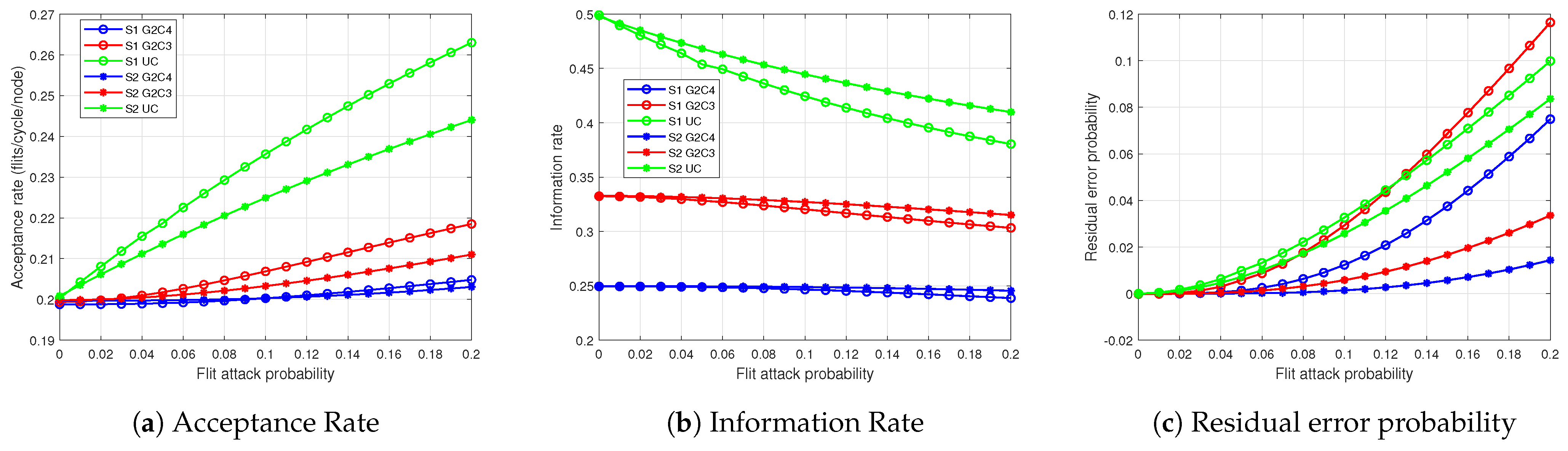
Application of the model to NoC:
The
NoC was investigated with an identical ratio of attacking routers as in the
NoC, so that there are 128 attacking routers in this scenario. The total flit attack probability is similarly varied from 0 to
in steps of
. The results were computed over 5000 different locations of attacking routers and the average results for the residual error probability, acceptance rate and information rate are displayed in
Figure 6.
To understand the performance results for the
NoC, we need to first consider the average path length of such a NoC. With uniform random traffic pattern, the average path length of the
NoC is
hops, whereas for the
NoC it is
hops. The probability of encountering an attacking router with average path lengths of 6 hops and 22 hops are:
Since there is a significantly higher probability of passing through an attacking router in the
NoC, we can expect significantly higher rates of flit drops and modifications. As a result, residual error rates (
Figure 6a) are considerably higher in comparison to the
NoC. Similar to the performance for
NoC, in the
NoC S2 behaves better than S1: S2/G2C4 has less than half the residual error probability of S1/G2C4 at 0.2 flit attack probability. For G2C3, S1 has a
higher residual error probability than S2 at
attack probability. For UC case, the performance of S1 and S2 are similar, which is already expected from Equations (8) and (23). In S1, it is observed that the redundancy of NC is no longer sufficient since at the high attack rates it becomes less likely to receive
G pairs of unmodified flits, resulting in a worse performance than UC. At
attack probability G2C3 has a
higher error rate and G2C4 has approximately the same error rate as UC.
Another reason for the lower performance of NC compared to UC in S1 is the limitation of the ARQs and retransmissions to one per transmission unit, which is
C pairs of flits for NC and one pair for UC. The effect of this can be observed in
Figure 6b where the high error rates result in an increase in the issue of ARQs and retransmissions, increasing the average rates of flit injection, i.e., the flit acceptance rate. In S1, UC has a
and
higher flit acceptance rate than G2C3 and G2C4 respectively. Between S1 and S2, the latter starts with lower acceptance rates. However, in the S2 coded cases the ARQ and retransmission rates increase rapidly with increasing attack probability becoming close to S1 at 0.2 attack probability. This results in a rapidly decreasing information rate as can be observed in
Figure 6c so that for the coded cases, the difference between S1 and S2 becomes less than
at 0.2 attack probability. However, since with similar acceptance rate S2 achieves a much lower residual error rate, we can select S2 as the superior authentication scheme. In the S2 scheme, we find that G2C4 has
lower error rate but also
lower information rate than G2C3 at 0.2 attack probability. This means that to transmit the same amount of data, G2C4 requires approximately
more transmissions than G2C3. This may be a point to consider when choosing a transmission scheme for latency critical applications especially if the probability of attack is low.
5.5. Area Overhead
As can expected, securing the NoC communication incurs some area overhead. However, as we demonstrate in this section, the overhead is a reasonable one. Area overhead results due to authentication as well as due to network coding. Moreover, buffers are used at each sender NI to store a copy of transmitted flits to allow for retransmission when needed. The main contributors to the area overhead of the proposed schemes are summarized in
Table 6.
The mCrypton modules [
27] contribute to a significant area increase since a certain number of them is required in the NI to generate the authentication tags for the information flits, injected to and from the NoC. In S1 scheme, each tag generation requires 39 cycles whereas in S2 scheme 26 cycles are needed. Data flits injected into the NoC and data flits incoming from the NoC (also including retransmitted flits) are served by a number of crypto modules working in parallel. The number of crypto modules must be sufficient so that the rate of flits queuing up is balanced by the service rate of the crypto modules. We assumed the total average flit injection at the sender side of the NI is 0.2 flits/cycle. As we assumed uniform random communication, there is also an equal flit injection into receiver side of the NI. Flits at both the sender and receiver side must be authenticated. However, in S1 half of the injected flits are tag flits. Thus, the total incoming rate of flits for the tag generation queue ( denoted as
) is
flits/node/cycle. Similarly, in S2,
flits/node/cycle. However, exact value of
is affected by drops and by (successful) retransmissions of flits incoming from NoC. The total flit incoming rate (from NoC) consists of flits which are not dropped, either originally transmitted flits or retransmitted flits. Considering UC case (which has the highest number of retransmissions), we can evaluate
at a module
a using Equation (11) and Equation (25) for S1 and S2 respectively:
By averaging over all modules, we obtain the value of for S1 and S2 at different drop and modification probabilities. With no drop probability i.e., , the maximum value of is obtained: flits/node/cycle for S1 and flits/node/cycle for S2.
Using Erlang’s C formula [
32], we next estimate the number of crypto modules needed so that probability that an incoming flit finds all crypto modules busy and must be queued is less than 0.05. The service rate of the crypto modules for S1 and S2 are 1/39 flits/cycle and 1/26 flits/cycle respectively. Since S2 has the higher
, we use this value in our estimation to find that with 18 crypto modules, a service level greater than
is achieved. Even a slight reduction to 15 crypto modules decreases the service level to
. The area of each mCrypton unit as given in [
27] is 2681 gate equivalents (GEs) so that for 18 mCryptons, the total area overhead is
GEs. To determine the actual overhead of these cryptomodules, we compare it to the total area of a state-of-the-art MPSoC. We thus consider the MPSoC Tomahawk 4 [
33] with total area 24.43 MGEs comprised of a hexagonal NoC connecting 6 processing modules in addition to a global memory. A total 10 NIs are present whose communication should be protected. Assuming 18 crypto modules per NI, this means an area overhead of
GEs over 24.43 MGEs or only ≈1.98%.
The matrix multiplications in the GF domain performed in network coding (
Section 3.2) also increase the area. To simplify the multiplication process in the GF domain, we use look-up tables (LUTs) in which all the results of the multiplication over GF(
) are stored. The LUT was implemented in Verilog hardware description language and functionally verified. When synthesized in 65 nm CMOS technology, each LUT had an area of 118 GEs. For each flit in S1, 18 symbols of 4 bits each (2 symbols for the GEV and 16 symbols for the 64 bits data) need to be encoded. Due to the generation size of
, 2 encoding coefficients are necessary for the computation of one linear combination. Hence in S1,
or 36 LUTs are required to produce one combination. In S2, fewer symbols need to be encoded since the data block is only 32 bits (
Section 4.3). The multiplication of this flit of size 10 symbols with the 2 encoding coefficients requires thus 20 LUTs. The NC scheme G2C4 has the greatest number of combinations and for this case in S1, we need a total of
or 144 LUTs. These LUTs incur a total area overhead of
or
GEs in each NI. Our considered state-of-art MPSoC ([
33]) has 10 NIs so that the area overhead incurred is
GEs, which is an increase of
% for the MPSoC. The decoding of the generation at the receiver requires a multiplication with the inverse of the
encoding matrix. This can be achieved easily via the determinant method. As shown in
Section 3.2, the decoding process requires fewer multiplications as the matrices are smaller, so that further LUTs are not required.
We know that depending on their size, buffers can occupy large area and also consume significant power. Buffers are used in the NI to store transmitted flits so that the tag does not need to be generated again for a retransmission. To determine how large buffers are needed, let us consider for how long flits should be stored in these buffers. This duration should be long enough so that when the ARQ arrives, the flit is still present in the buffer. In our investigated scenarios, the flits of a generation are monitored at the receiver using a timer that is restarted whenever a flit of the generation arrives. A flit is assumed to be missing and an ARQ is issued if no new flits arrive within 8 cycles after the last flit. The ARQ reaches the target after a total round trip delay plus the 8 cycles. In the NoC, the highest distance between 2 nodes is 15 hops, considering XY routing. In our NoC, each hop required 2 cycles so that the ARQ reaches the target node after a total delay of or 68 cycles. With a retransmission buffer of size flits deep and an injection rate of flits/node/cycle, the original flit is stored in the buffer for cycles on average before it is overwritten. For the original flit to be found when the ARQ arrives, the flit must be in the buffer for at least 68 cycles, i.e., . Thus, with = or ∼14, the original flit can be found.
A flit modification is detected after 26 or 39 cycles after receiving the flit, after which an ARQ is issued. Thus, the ARQ will reach the sender or cycles respectively after the original flit was transmitted. Thus, for the original flit (or flits in S1) still to be present in the buffer, the flit must be present for at least 99 or 86 cycles. Thus, , i.e., or 18 flits deep. This demonstrates that the buffer required to store transmitted flits is very small. Our reference MPSoC has a very small network size where the nodes have a maximum distance of 3 hops so that even smaller sized buffers are necessary. The effect of this buffer on the total area can be considered insignificant. Thus, in total the area overhead is or .
6. Summary and Outlook
In this work, we proposed and thoroughly evaluated efficient authentication schemes to protect NoC communication against active attacks. By combining the usage of MACs for authentication and network coding for performance and resilience, we devised secure, highly robust, and efficient solutions. The evaluation of these new schemes is twofold: first of all, we performed extensive simulations with an cycle accurate NoC simulator covering different system parameters and attacker scenarios. Additionally, we developed an analytical model which describes the main performance metrics in a formalized manner. Thereby, we were able to examine the performance of our proposed schemes in additional scenarios, which are unfeasible to simulate. Furthermore, the analytical models provides insight into the system behaviour. Finally, the impact of our solution regarding chip area was analyzed.
Our evaluation showed, that the proposed solutions realize a robust protection scheme for NoC communication. This robustness is primarily rooted in the network coding: In the base scenario, the best solution S2/G2C4 reduces the residual error probability by up to ≈85.9% compared to uncoded UC solution. The acceptance rate reduction of ≈15.7% also reflects a more robust transmission as fewer flits were transferred. Additionally, this means that the overall network load is reduced with the proposed coded schemes. In the best scenario the residual error probability is reduced by ≈90.06% and the acceptance rate by ≈22.13%.
The addition of authentication and robustness implies additional costs: First, despite using an efficient lightweight block cipher, mCrpyton, as cryptographic primitive, the computation and verification of the MAC each takes up 39/26 cycles for S1/S2, respectively. In contrast, the network coding implementation via LUTs has negligible impact on the latency. Second, the addition of network coding decreases the information rate, i.e., for successful transmission more flits are sent per data flit. For the most robust solution G2C4 this means 4 flits instead of 2 in the uncoded case need to be send.
The developed analytical model overall confirmed the simulation results obtained in the different scenarios. Additionally, it showed that for a 32 × 32 NoC with 128 attacking routers matching results could be obtained: Although successful transmission becomes significantly harder in this extreme setting, the coded solution S2/G2C4 provided the best results, with residual error rates reduced by ≈54.76% compared to the uncoded case.
Overall, the solution S2/G2C4 consistently provided the most robust efficient protection over all scenarios and parameters. With this approach, we provide efficient detection of active attacks. Moreover, the redundancy provided by network coding is very effective against dropping and modification of flits.
This enhanced robustness and additional security can be achieved with a minimal area overhead of ≈2.68% in comparison to the total area of a state-of-the-art MPSoC.
Among many future research topics addressing the protection of NoC communication is the investigation of efficient key management for symmetric block ciphers. Current protection schemes do explicitly exclude key management and assume pairwise symmetric keys. The distribution and management of these secrets pose a demanding issue, since there is no out-of-band medium available. Therefore, the untrusted medium and endpoints need to be used to securely distribute symmetric keys.
Another possible topic for future work could be the investigation of the proposed schemes using different cryptographic primitives. A promising contender can be PRINCE [
34] as proposed in [
35]. Its main advantage is the performance of 1 cycle per block, which would significantly reduce the latency of the current solution. Furthermore, the number of required cryptographic modules and their respective queues could be reduced. Although a PRINCE module has a greater area compared to mCrypton, the reduced total number of these required could result in a comparably similar or even lower area overhead.
Another intended way forward is to further analyze the trade-offs and system parameters of the communication scheme: The application of more sophisticated routing schemes, e.g., Valiant [
36] or ROMM [
37], and multipath routing could lead to enhanced robustness against attackers. In fact, the analytical model is flexible and already applicable to multipath routing. Furthermore, the impact of the retransmission solution will be analyzed—the retransmission limit could be altered or removed to allow for additional retransmission and the usage of ARQs could be combined with an ACK-based solution. Finally, the application of burst mode for message transmission in the NoC and its implications for the proposed secure protocols will be investigated.


 ,
, 


