
A 560 GHz Sub-Harmonic Mixer Using Half-Global Design Method


Abstract
1. Introduction
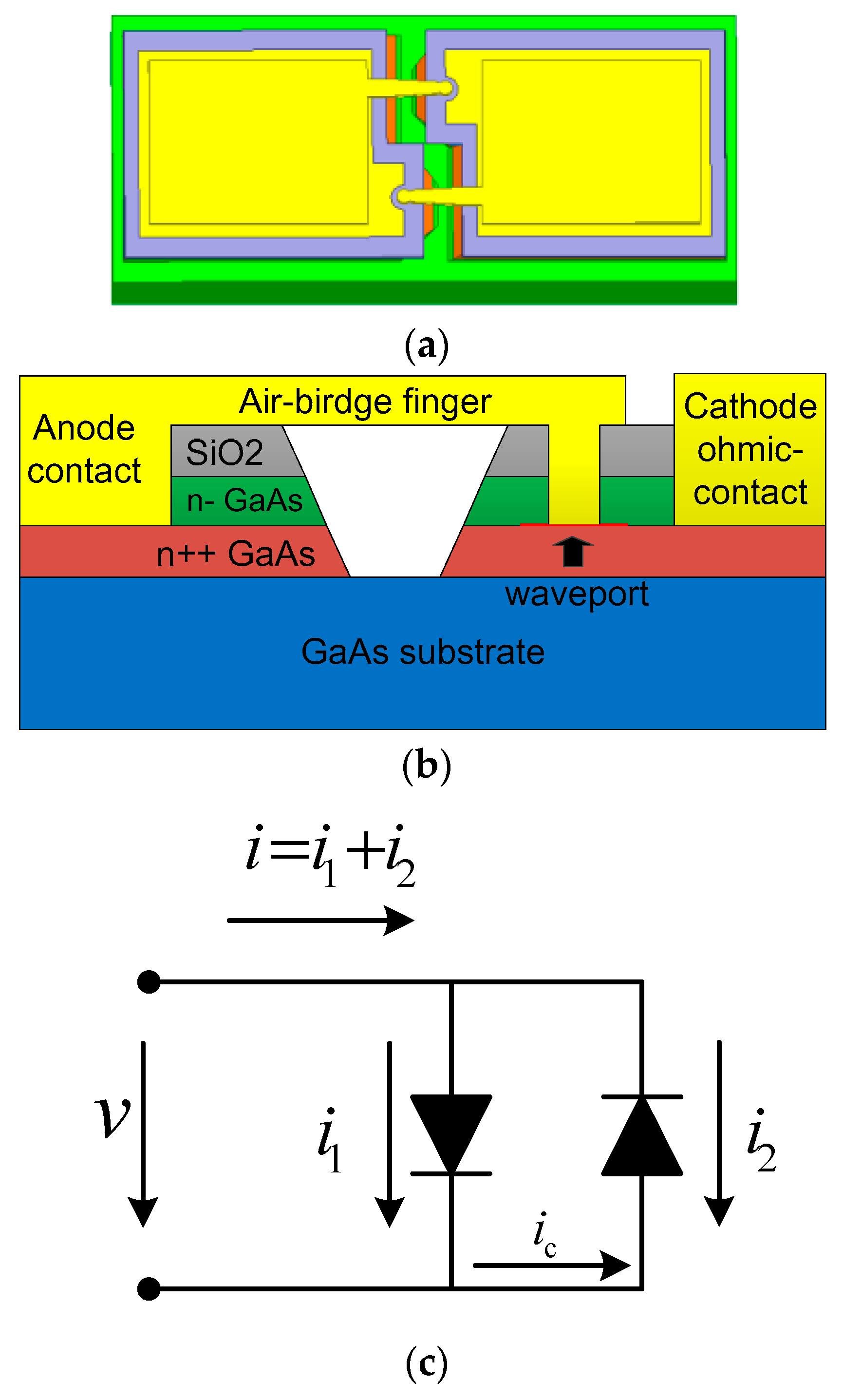
2. Diode Modeling
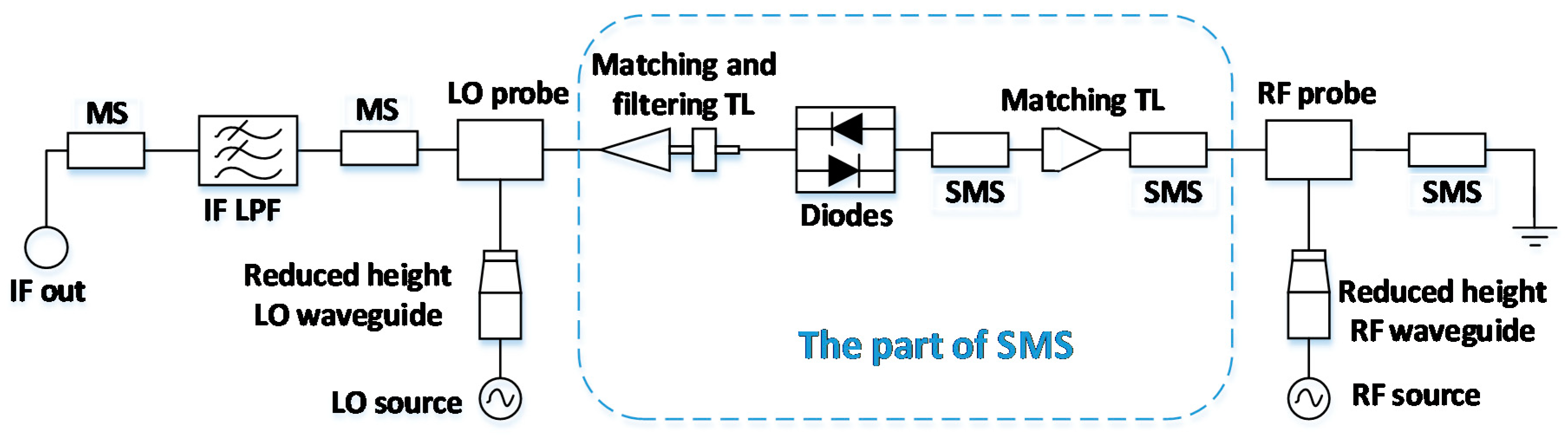
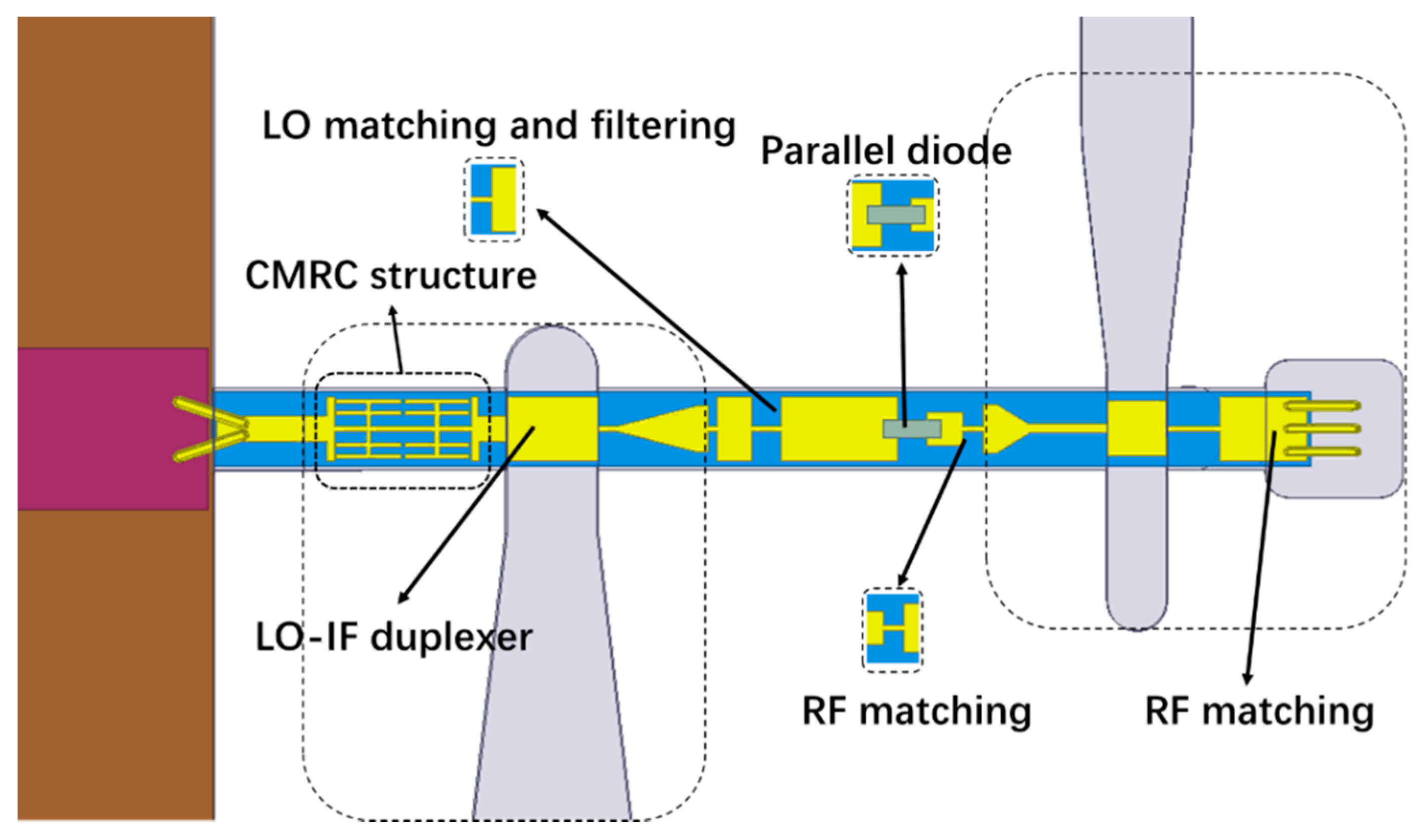
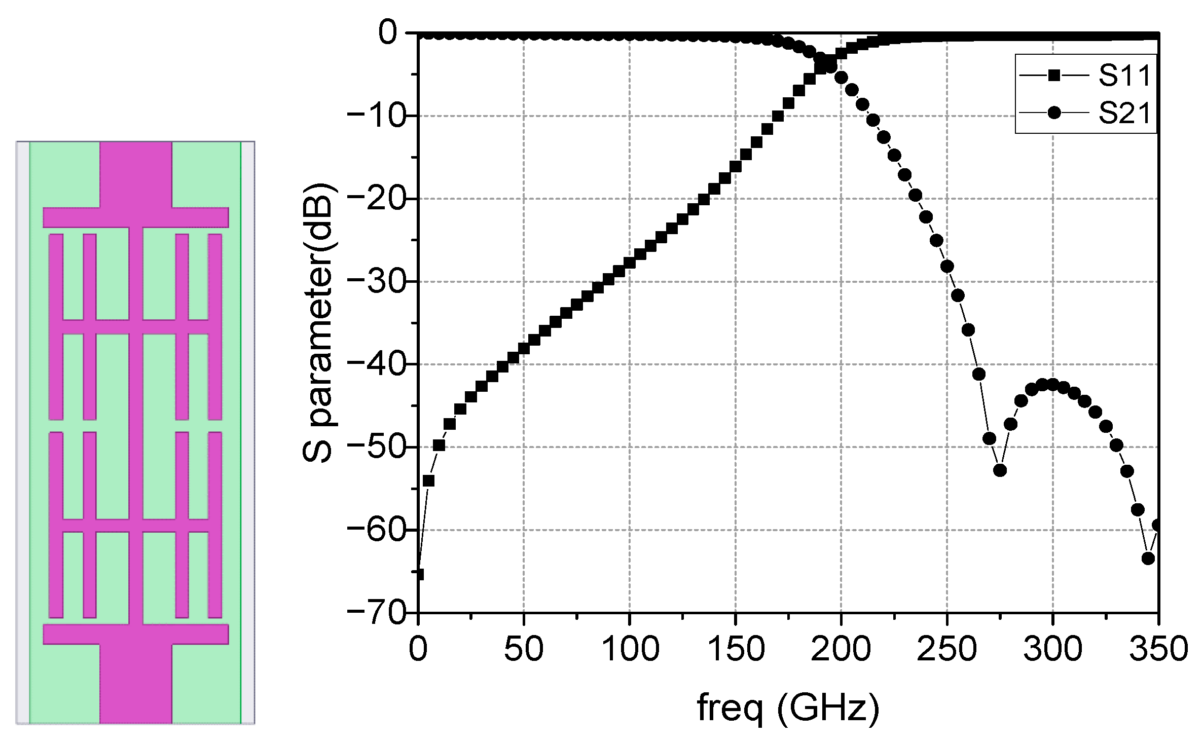
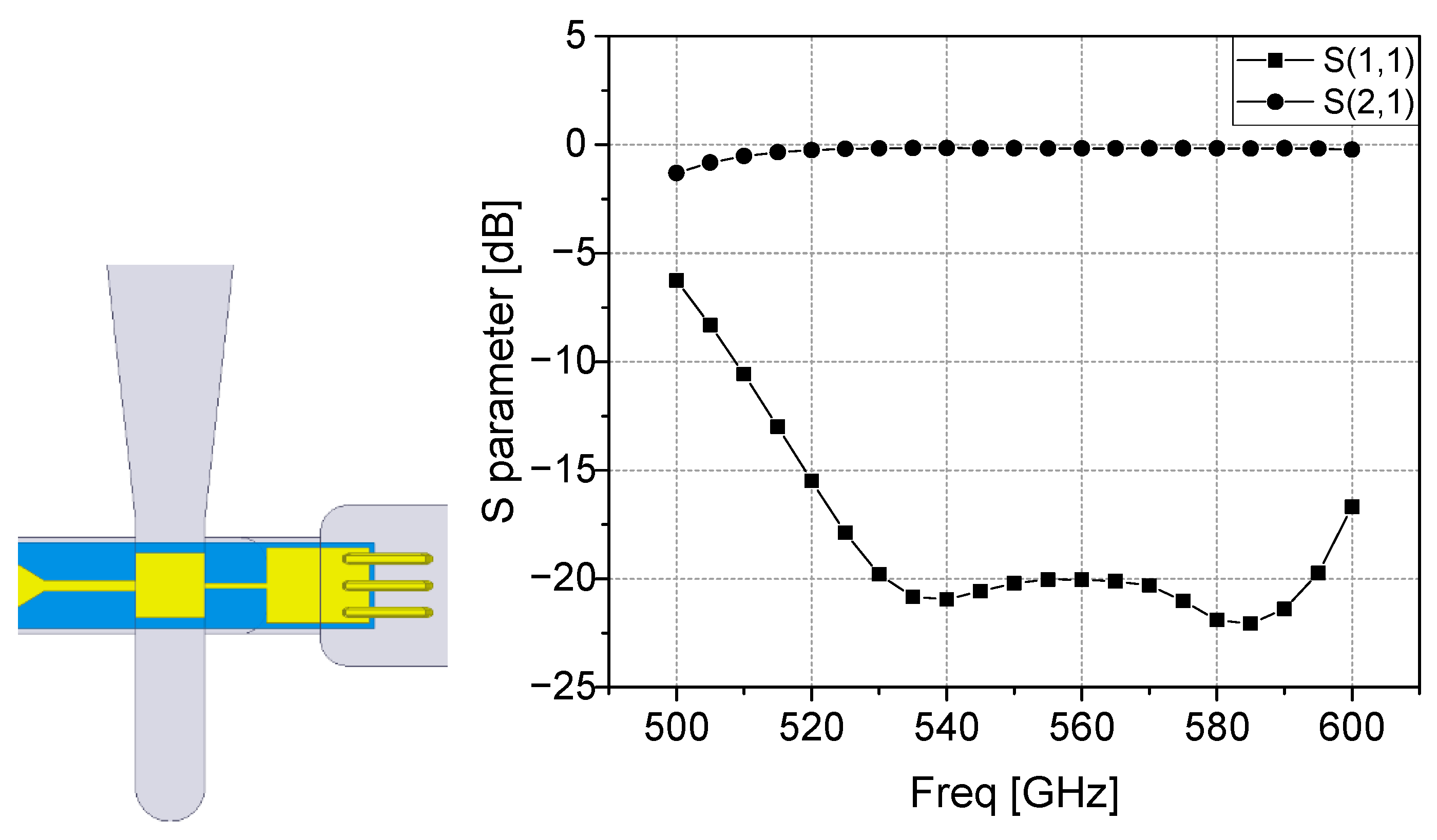
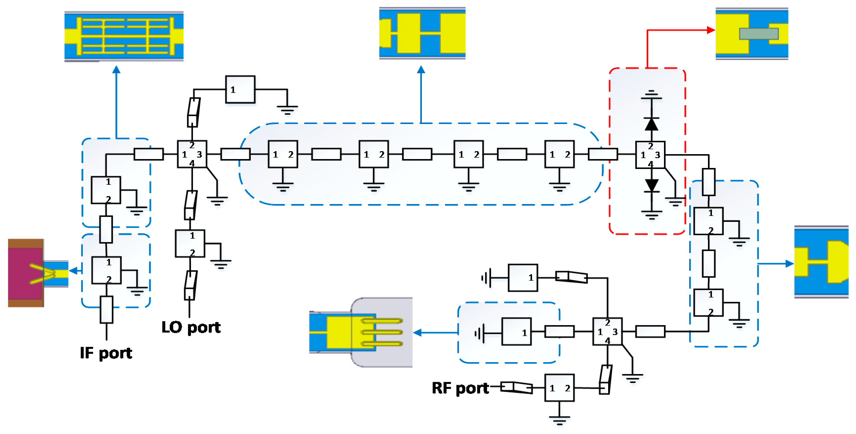
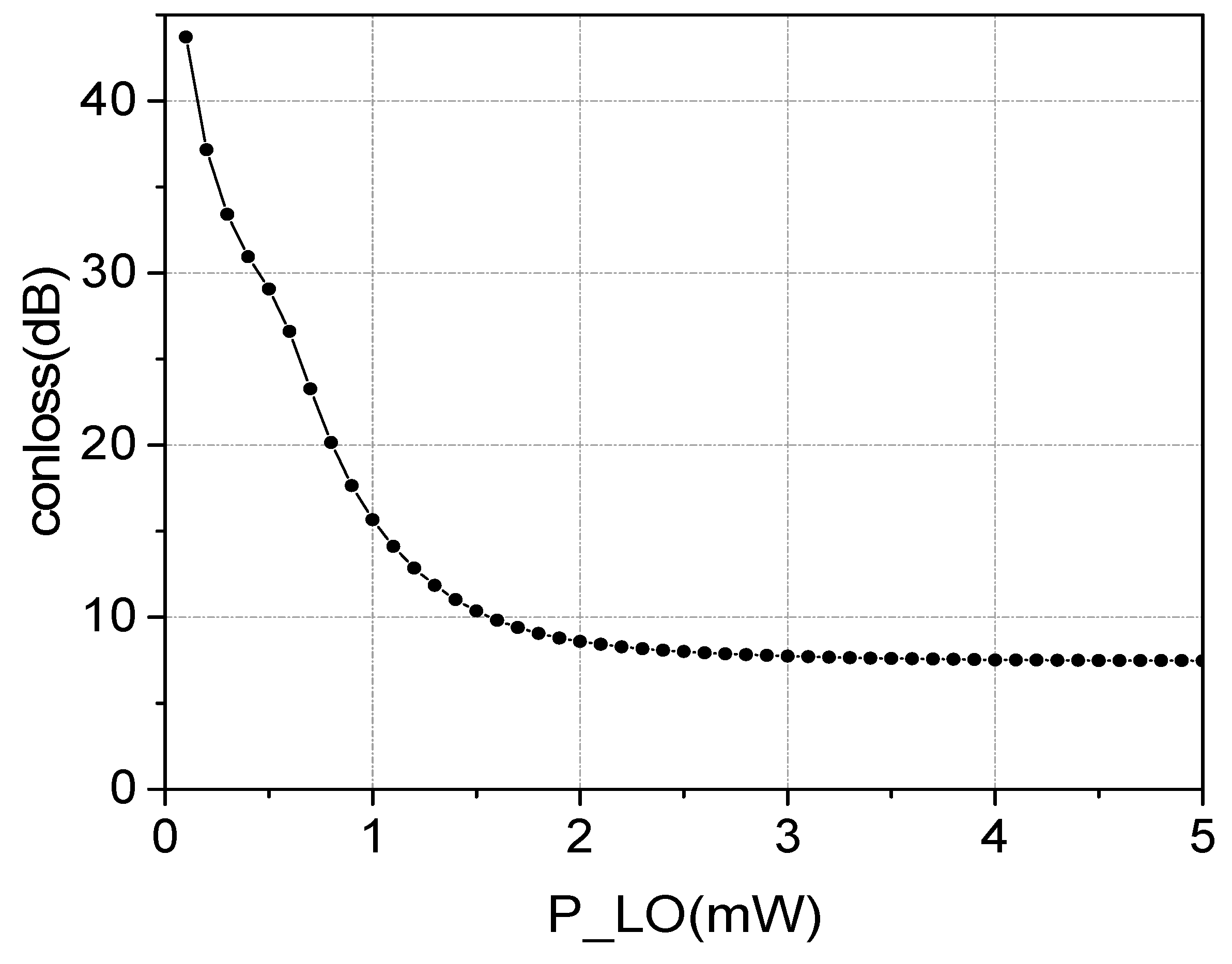
3. Circuit Design
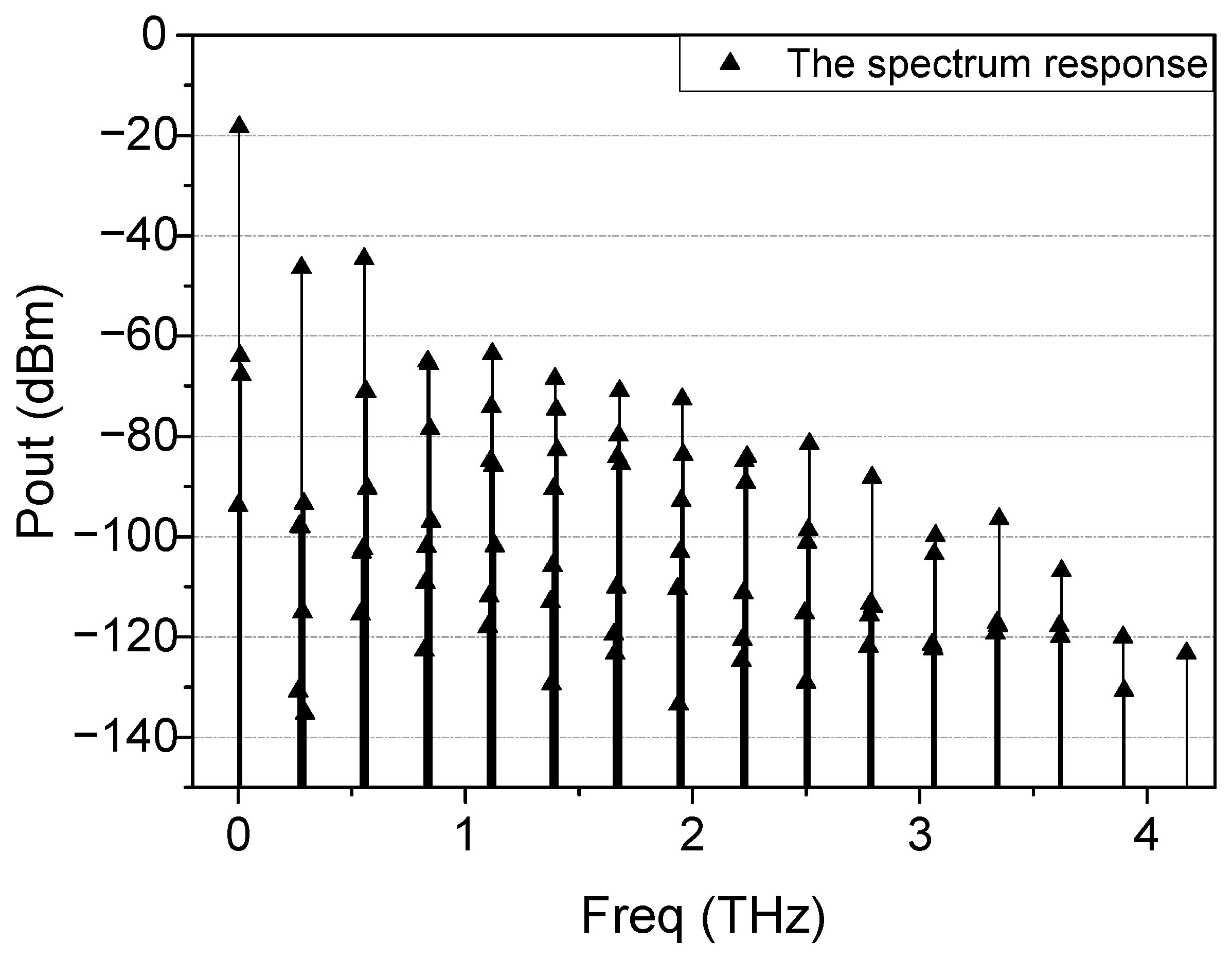
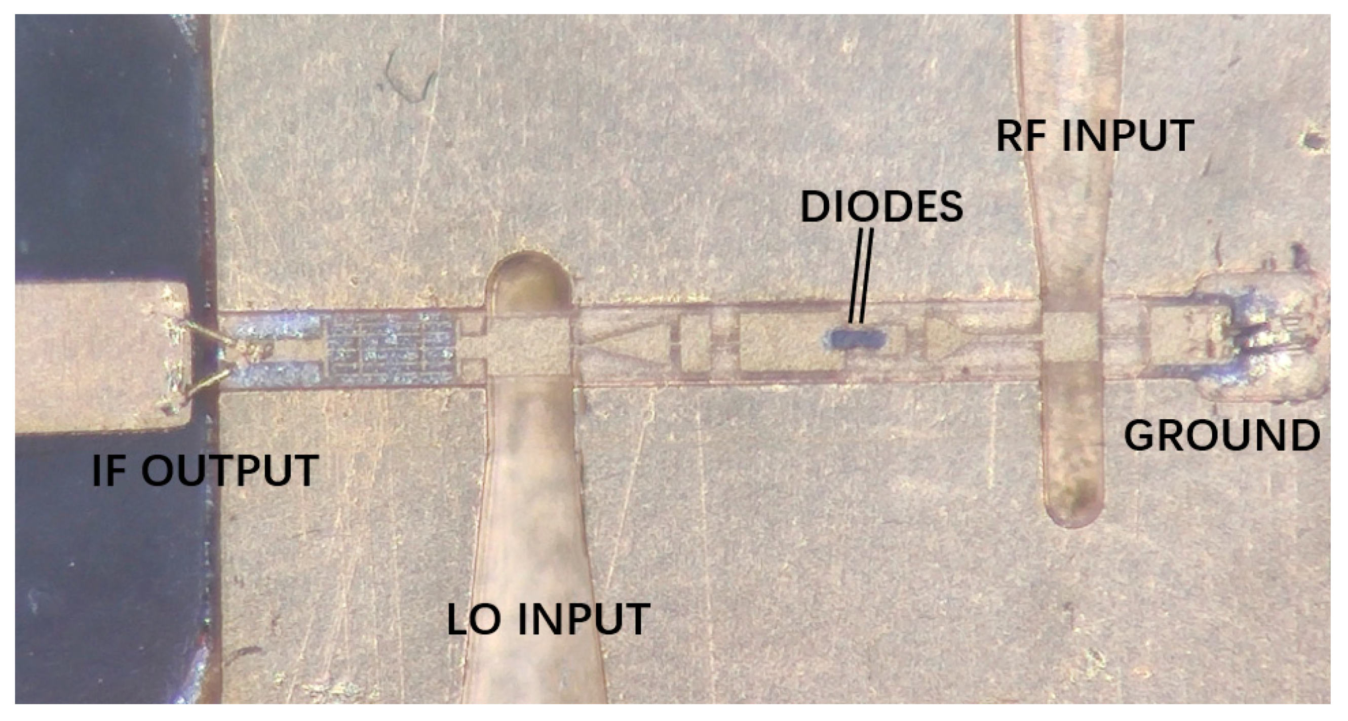
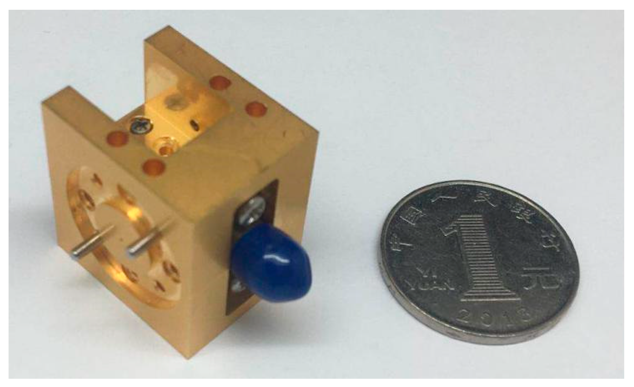
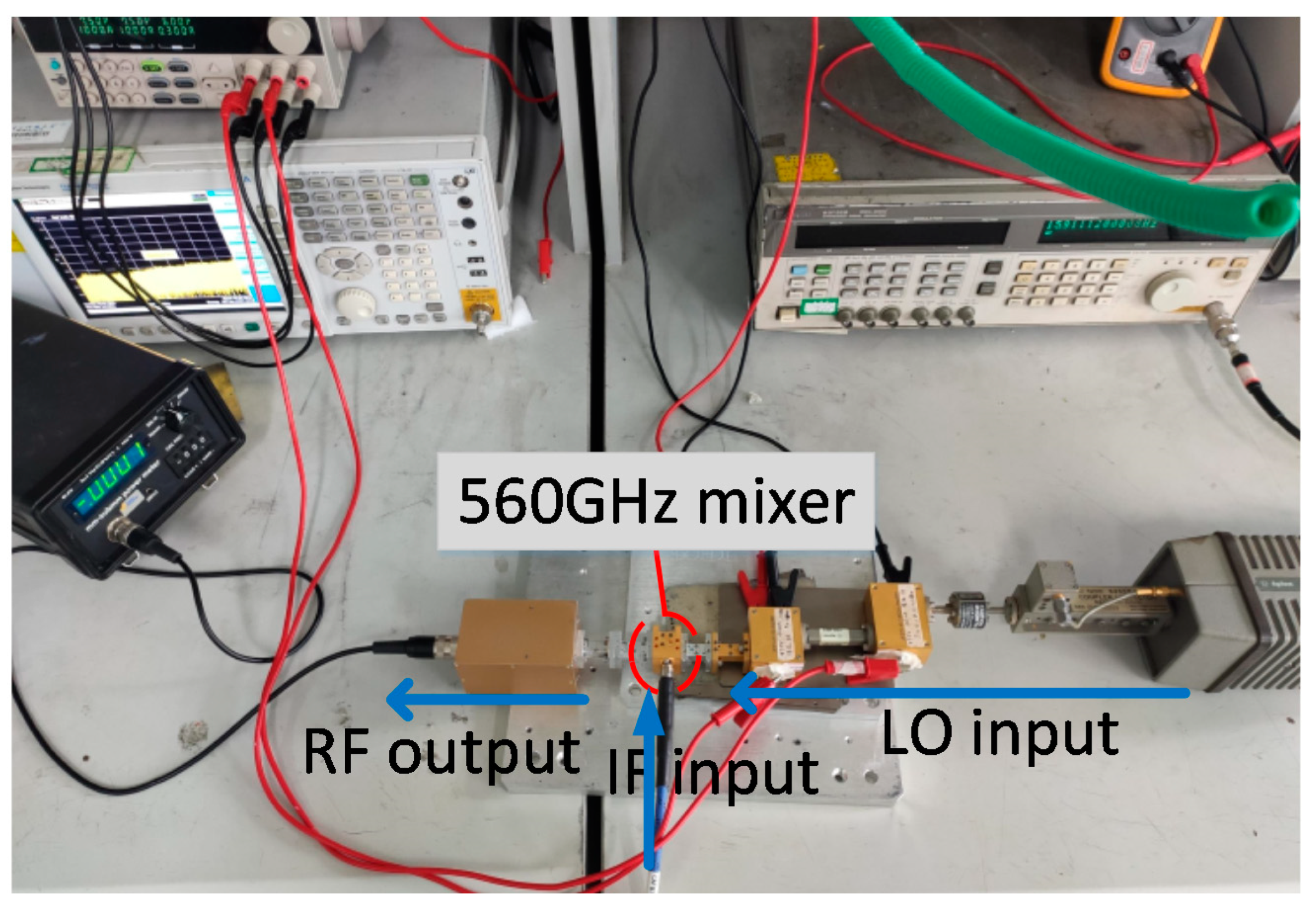
4. Fabrication and Measurement
5. Conclusions
Author Contributions
Funding
Conflicts of Interest
References
- Siegel, P.H. Terahertz technology. IEEE Trans. Microw. Theory Tech. 2002, 50, 910–928. [Google Scholar] [CrossRef]
- Thomas, B.; Gill, J.; Maestrini, A.; Lee, C.; Lin, R.; Sin, S.; Peralta, A.; Mehdi, I. An integrated 520–600 GHz GHz sub-harmonic mixer and tripler combination based on GaAs MMIC membrane planar Schottky diodes. In Proceedings of the 35th International Conference on Infrared, Millimeter, and Terahertz Waves, Rome, Italy, 5–10 September 2010; pp. 1–2. [Google Scholar]
- Eissa, M.H.; Awny, A.; Ko, M.; Schmalz, K.; Elkhouly, M.; Malignaggi, A.; Ulusoy, A.C.; Kissinger, D. A 220–275 GHz direct-conversion receiver in 130-nm SiGe:C BiCMOS technology. IEEE Microw. Wirel. Compon. Lett. 2017, 27, 675–677. [Google Scholar] [CrossRef]
- Shivan, T.; Weimann, N.; Hossain, M.; Stoppel, D.; Boppel, S.; Ostinelli, O.; Doerner, R.; Bolognesi, C.R.; Krozer, V.; Heinrich, W. A highly efficient ultrawideband traveling-wave amplifier in InP DHBT technology. IEEE Microw. Wirel. Compon. Lett. 2018, 28, 1029–1031. [Google Scholar] [CrossRef]
- Yoon, D.; Kim, J.; Yun, J.; Kaynak, M.; Tillack, B.; Rieh, J.-S. 300-GHz Direct and Heterodyne Active Imagers Based on 0.13-μm SiGe HBT Technology. IEEE Trans. Terahertz Sci. Technol. 2017, 7, 536–545. [Google Scholar] [CrossRef]
- Kim, J.; Yoon, D.; Yun, J.; Song, K.; Kaynak, M.; Tillack, B.; Rieh, J.-S. Three-dimensional terahertz tomography with transistor-based signal source and detector circuits operating near 300 GHz. IEEE Trans. Terahertz Sci. Technol. 2018, 8, 482–491. [Google Scholar] [CrossRef]
- Schultz, J.; Herald, D.; Xu, H.; Liu, L.; Bass, R.; Weikle, R.; Lichtenberger, A. The Design, Fabrication and Test Results of a 1.6 THz Superconducting Hot Electron Bolometer Mixer on SOI. IEEE Trans. Appl. Supercond. 2009, 19, 297–300. [Google Scholar] [CrossRef]
- Montazeri, S.; Grimes, P.K.; Tong, C.-Y.E.; Bardin, J.C.; Tong, C.E. A 220-GHz SIS Mixer Tightly Integrated with a Sub-Hundred-Microwatt SiGe IF Amplifier. IEEE Trans. Terahertz Sci. Technol. 2015, 6, 133–140. [Google Scholar] [CrossRef]
- di Gaspare, A.; Giliberti, V.; Casini, R.; Giovine, E.; Evangelisti, F.; Ortolani, M. Sub-terahertz mixer based on heterostructure field effect transistor with integrated antennas. In Proceedings of the 2013 7th European Conference on Antennas and Propagation, Gothenburg, Sweden, 8–12 April 2013; pp. 1736–1739. [Google Scholar]
- Pfeiffer, U.R.; Mishra, C.; Rassel, R.M.; Pinkett, S.; Reynolds, S.K. Schottky barrier diode circuits in silicon for future millimeter-wave and terahertz applications. IEEE Trans. Microw. Theory Tech. 2008, 56, 364–371. [Google Scholar] [CrossRef]
- Redo-Sanchez, A.; Zhang, X.C. Terahertz science and technology trends. IEEE J. Sel. Top. Quantum Electron. 2008, 14, 260–269. [Google Scholar] [CrossRef]
- Tonouchi, M. Prospect of terahertz technology. In Proceedings of the International Conference on Applied Electromagnetics and Communications, Dubrovnik, Croatia, 24–26 September 2007; pp. 1–4. [Google Scholar]
- Liu, C.; Li, Q.; Xiong, Y.Z. A 340 GHz MMIC 4× sub-harmonic mixer using silicon-based Schottky barrier diodes. In Proceedings of the 2015 IEEE International Wireless Symposium (IWS 2015), Shenzhen, China, 30 March–1 April 2015; pp. 1–4. [Google Scholar] [CrossRef]
- Michaelsen, R.S.; Johansen, T.K.; Krozer, V. Design of a ×4 subharmonic sub-millimeter wave diode mixer, based on an analytic expression for small-signal conversion admittance parameters. In Proceedings of the 2013 SBMO/IEEE MTT-S International Microwave & Optoelectronics Conference (IMOC), Rio de Janeiro, Brazil, 4–7 August 2013; pp. 1–4. [Google Scholar] [CrossRef]
- Cohn, M.; Degenford, J.E.; Newman, B.A. Harmonic Mixing with an Anti-Parallel Diode Pair. In Proceedings of the S-MTT International Microwave Symposium Digest, Atlanta, GA, USA, 12–14 June 1974; pp. 171–172. [Google Scholar] [CrossRef]
- Gaojian, L.; Jun, L.; Hui, X.; Xiaoyang, Z.; Shuantao, L.; Hongxi, Y. Design of a 220 GHz subharmonic mixer based on plannar Schottky diode. In Proceedings of the 2017 IEEE Asia Pacific Microwave Conference (APMC), Kuala Lumpar, Malaysia, 13–16 November 2017; pp. 418–421. [Google Scholar]
- Mehdi, I.; Marazita, S.; Humphrey, D.; Lee, T.-H.; Dengler, R.; Oswald, J.; Pease, A.; Martin, S.; Bishop, W.; Crowe, T.; et al. Improved 240-GHz subharmonically pumped planar Schottky diode mixers for space-borne applications. IEEE Trans. Microw. Theory Tech. 1998, 46, 2036–2042. [Google Scholar] [CrossRef]
- Cui, J.; Zhang, Y.; Xia, D.; Xu, Y.; Xiao, F.; Yan, B.; Xu, R. A 220 GHz broadband sub-harmonic mixer based on global design method. IEEE Access 2019, 7, 30067–30078. [Google Scholar] [CrossRef]
- Cui, J.; Zhang, Y.; Xu, Y.; Ye, L.; Xiao, F.; Yan, B.; Xu, R. A 200–240 GHz Sub-Harmonic Mixer Based on Half-Subdivision and Half-Global Design Method. IEEE Access 2020, 8, 33461–33470. [Google Scholar] [CrossRef]
- Zhong, F.; Zhang, B.; Fan, Y.; Zhao, M.; Yang, X. A Broadband W-band Subharmonic Mixers Circuit Based on Planar Schottky Diodes. In Proceedings of the 2012 International Conference on Industrial Control and Electronics Engineering, Xi’an, China, 23–25 August 2012; pp. 792–794. [Google Scholar] [CrossRef]
- Hu, N.; Xie, W.; Liu, J.; Liu, S.; Zeng, Q.; Luo, Y. Modeling of GaAs Multiplier Schottky Diode in Terahertz Band. In Proceedings of the 2019 IEEE International Conference on Computational Electromagnetics (ICCEM), Shanghai, China, 20–22 March 2019; pp. 1–3. [Google Scholar] [CrossRef]
- Wu, C.; Zhang, Y.; Xu, Y.; Bo, Y.; Xu, R. Dual Lumped Ports Technique and Its Applications in Modeling of Planar Schottky Diode in THz Band. IEEE Access 2020, 8, 38001–38009. [Google Scholar] [CrossRef]
- Schlecht, E.; Gill, J.; Dengler, R.; Lin, R.; Tsang, R.; Mehdi, I. A Unique 520–590 GHz Biased Subharmonically-Pumped Schottky Mixer. IEEE Microw. Wirel. Compon. Lett. 2007, 17, 879–881. [Google Scholar] [CrossRef]
- He, Y.; Tian, Y.; Miao, L.; Jiang, J.; Deng, X. A broadband 630–720 GHz Schottky based sub-harmonic mixer using intrinsic resonances of hammer-head filter. China Commun. 2019, 16, 76–84. [Google Scholar]
- Zhao, H.; Drakinskiy, V.; Sobis, P.; Hanning, J.; Bryllert, T.; Tang, A.Y.; Stake, J. Development of a 557 GHz GaAs monolithic membrane-diode mixer. In Proceedings of the 2012 International Conference on Indium Phosphide and Related Materials, Santa Barbara, CA, USA, 27–30 August 2012; pp. 102–105. [Google Scholar] [CrossRef]
- Treuttel, J.; Gatilova, L.; Maestrini, A.; Moro-Melgar, D.; Yang, F.; Tamazouzt, F.; Vacelet, T.; Jin, Y.; Cavanna, A.; Mateos, J.; et al. A 520–620-GHz Schottky Receiver Front-End for Planetary Science and Remote Sensing With 1070 K–1500 K DSB Noise Temperature at Room Temperature. IEEE Trans. Terahertz Sci. Technol. 2016, 6, 148–155. [Google Scholar] [CrossRef]


Publisher’s Note: MDPI stays neutral with regard to jurisdictional claims in published maps and institutional affiliations. |
© 2021 by the authors. Licensee MDPI, Basel, Switzerland. This article is an open access article distributed under the terms and conditions of the Creative Commons Attribution (CC BY) license (http://creativecommons.org/licenses/by/4.0/).
Share and Cite
Zhang, B.; Zhang, Y.; Pan, L.; Li, Y.; Cui, J.; Xu, R.; Yan, B. A 560 GHz Sub-Harmonic Mixer Using Half-Global Design Method. Electronics 2021, 10, 234. https://doi.org/10.3390/electronics10030234
Zhang B, Zhang Y, Pan L, Li Y, Cui J, Xu R, Yan B. A 560 GHz Sub-Harmonic Mixer Using Half-Global Design Method. Electronics. 2021; 10(3):234. https://doi.org/10.3390/electronics10030234
Chicago/Turabian StyleZhang, Bo, Yong Zhang, Liucheng Pan, Yu Li, Jianhang Cui, Ruimin Xu, and Bo Yan. 2021. "A 560 GHz Sub-Harmonic Mixer Using Half-Global Design Method" Electronics 10, no. 3: 234. https://doi.org/10.3390/electronics10030234
APA StyleZhang, B., Zhang, Y., Pan, L., Li, Y., Cui, J., Xu, R., & Yan, B. (2021). A 560 GHz Sub-Harmonic Mixer Using Half-Global Design Method. Electronics, 10(3), 234. https://doi.org/10.3390/electronics10030234