Article

Tracking and Synchronization with Inversion-Based ILC for a Multi-Actuator-Driven Wafer Inspection Cartridge Transport Robot System

1
School of Mechanical Engineering, Sungkyunkwan University, Suwon 16419, Korea
2
Department of Ultra Precision Machines & Systems, Korea Institute of Machinery & Materials, Daejeon 34103, Korea
3
Digital Transformation R&D Department, KITECH, Ansan 15588, Korea
*
Author to whom correspondence should be addressed.
Electronics 2021, 10(23), 2904; https://doi.org/10.3390/electronics10232904
Submission received: 13 October 2021 / Revised: 19 November 2021 / Accepted: 22 November 2021 / Published: 24 November 2021
(This article belongs to the Section Systems & Control Engineering)

Abstract

:
This paper proposes a simple tracking and synchronization control of a dual-drive system using inversion-based iterative learning control (IILC), which reformulates the model at each iteration based on input/output data. By the power of the IILC, this work simplifies the dual-actuator-driven dynamic system control problem that is normally addressed with a MIMO method. This work also shows the potential of the IILC for nonlinear system applications by reformulating the model at each iteration based on the input/output data. An analytical representation of the iteration-varying IILC followed by simulations is provided. A set of physical system testings with a dual-motor gantry and a semiconductor wafer inspection robotic system are carried out to verify the control method.

1. Introduction

In various manufacturing scenarios, a multi-motor-driven system is popularly used for accurate and high-speed transport of heavy objects [1,2]. In recent years, especially in the semiconductor industry, the inspection system’s target object has changed from a single proving to a heavy-cartridge type multi-probing unit or, in advanced display vacuum fabrication, from a simple linear motion to a heavy gantry.
One of the popular developments on the concept of multi-probes is a system that combines a probe card, wafer, and chuck to create an integrated cartridge and inspect multiple cartridges simultaneously through multiple channels [3,4]. As the target weight for the cartridge transport robot in these systems increases and affects the takt time, a transport operation using a multi-axis actuator is required, and stable control for this is also an important issue. Consequently, one of the main problems with this system is the synchronization of multiple actuators.
In the dual-gantry system commonly used in the industry, the bridge connecting each axis is rigid, and so are the connection joints. Even a tiny distortion could result in a prohibitive situation, especially in chip manufacturing. To reduce this problem, many studies have been carried out. One of the typical examples, including Kamaldin, proposed a flexible joint structure [5], although the added degree of freedom costs a complication in designing controls mostly with synchronization issues.
There are some typical categories of synchronization controls. First, the synchronized master motion command method is popularly adopted in many applications [6,7]. This method considers each axis an independent master axis and composes an independent control loop but provides a synchronized motion command. Second, there is a master–slave method [8,9], which sets the motion of the master axis as a command of the slave. There is a slight delay between master and slave in this method. There is also a problem that errors due to disturbances in the slave axis are not considered in the master axis control loop. The third method is a cross-coupled type control method, which considers the relative difference in the motion of each axis, and is currently the most widely used method [10,11,12,13,14]. Recently, methods such as the mean deviation method using deviation from the average value of motion of each axis or control using NN have been introduced [15,16]. In addition, other studies utilizing sliding mode (SMC) [17,18], modified optimal control [13,19], or adaptive control have been introduced. Typical examples are shown in [20,21,22].
A robotic transport system commonly adopted in many manufacturing processes has a repetitive identical moving geometric path operation. Moreover, it works with harsh environmental parameter changes such as temperature, friction, and operating pressure. Iterative learning control (ILC) would be a competitive candidate for a system that carries out such repetitive tasks [23,24,25]. However, limited capability in handling the transient response is one of the drawbacks of the ILC, especially when the input is not continuous. There have been studies on reducing the problem by adopting additional treatment such as input shaping or adding filters. Despite the limitation, since most repetitive robotic tasks required in industry are periodic wave-form-based motions, the ILC may still be a notable candidate.
A typical basic structure of the ILC is P-type ILC. Although it has simple formulation and implementation with acceptable accuracy, it has a notable disadvantage in convergence speed, along with many other ILC methods [26,27]. To overcome the drawback, the inversion-based ILC (IILC) has been proposed and tested [28,29,30,31]. It features a much faster convergence speed than the P-type and shows high convergence when selecting an appropriate gain. However, the limitation of IILC exists in the derivation process of the inversion model. It is not easy to derive an inversion model, and if the accuracy of the inversion model is not precise enough, the convergence will be rough. In addition, from the viewpoint of the Newton method, it is difficult to obtain the desired performance in the iteration-varying system or nonlinear system because previous studies used a fixed gradient in the iteration axis [32]. To compensate for these problems, this paper proposes a method to control tracking and synchronization through IILC based on the Newton method, which applies reformulation of the model at each iteration with simple inversion.
Considering the mechanism construction of those robotic transport systems where multiple actuators are coupled, the control for synchronization should be arranged through a MIMO/MISO architecture. Although, as mentioned earlier, there were many attempts to control these problems with a set of parallel SISO control systems, their efficiencies and accuracies were not verified with modern production systems. In addition, in MIMO architecture, the coupling term makes the system model complex, and the control system’s performance may deteriorate due to inaccuracy and uncertainty of the model. Noting the drawbacks of the previous attempts and advantages of the IILC, the present work tries to organize a set of parallel SISO controllers for the coupled actuator control. Using the constructed IILC, this work successfully synchronizes two motors and provides fairly precise accuracy in demanding engineering problems.
In Section 2, the problem definition of a multi-motor system and system components in a manufacturing system are explained. Section 3 introduces the proposed ILC and analyzes the characteristics of the convergence characteristics. In Section 4, a simulation of the proposed algorithm is performed. In Section 5, convergence for the algorithm is verified through an experiment and a comparative study. Robustness for the iteration-varying system is also verified in this section. Finally, Section 6 concludes this paper.

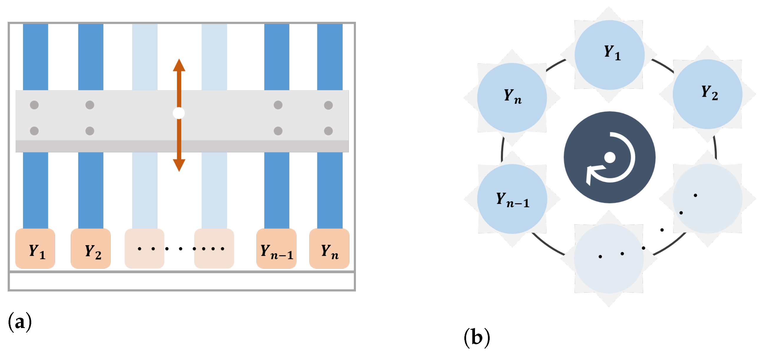
2. Problem Definitions

A schematic mechanical structure of a multi-driving system is shown in Figure 1. There are n driving axes, and all shafts are connected by one coupler or one driving shaft, a bridge. In general, end-effectors or load sides are mounted on the bridge, and extra motion freedom is given along the bridge when necessary. The target system to be applied in this work is a wafer multi-prove inspection cartridge transporter, an orthogonal robot system carrying a heavy-weight cartridge. Its main operation is in the vertical direction by two or more linear actuators. A motor-driven cartridge pusher working in the horizontal direction is mounted on its bridge. In such a dual-drive system, since an accurate synchronization of the multiple motors has been a challenging issue, the problem should be carefully addressed under MIMO or MISO system arrangements. Many previous studies have solved this problem in a way that involves a series of complicated procedures.
As mentioned earlier, this work suggests a much simpler method using the IILC formulated based on SISO systems. In this presentation, we have to admit that this proposed method cannot substitute all the MIMO/MISO problems, although it shows fairly accurate performances in the problems shown. In other words, the coupled dual-motor dynamic system is controlled with parallel SISO model-based IILCs with accurate control errors. A typical dual-motor gantry is constructed, and it is controlled with the proposed method. The gantry is to be modified for aggravated physical situations, and it is controlled with the controller. Finally, the method is verified with a wafer cartridge transport robot that incorporates multi-motors.

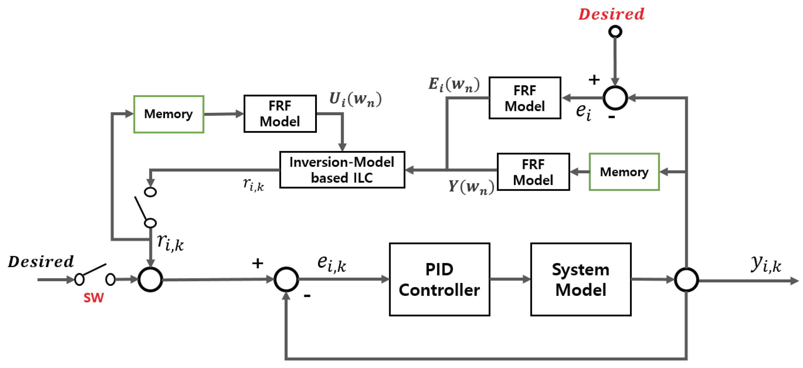
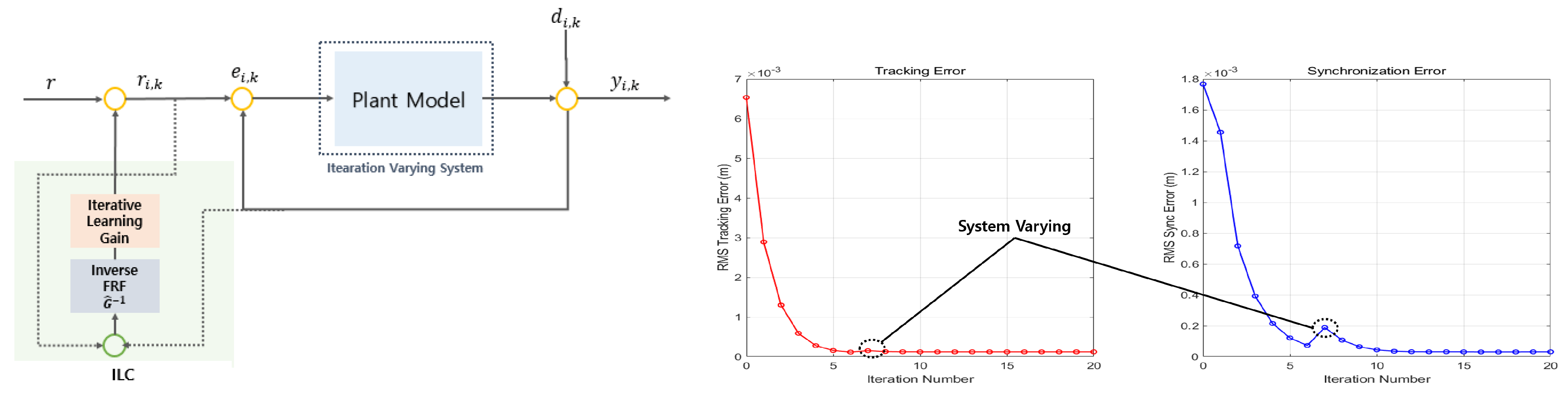
3. An Inversion-Based Iterative Learning Control

3.1. Algorithm

Although it does not guarantee a fast convergence speed, the typical P-type ILC provides good accuracy in various problems. As a result, application in actual industrial applications is less efficient, especially for the parallel SISO problems used in this work. On the other hand, the inversion-based ILC ensures faster convergence with high precision accuracy through the model-based update, even though it has limitations for the iteration-varying or nonlinear systems. Note that a system shows similar characteristics to a class of nonlinear systems when its characteristics are iteration dependent (iteration varying). This study proposes a new synchronization method based upon a modified ILC, called inversion-based iterative learning control, for the systems that change their system parameters while the iteration proceeds.
The main idea of the IILC is to estimate the inverse model from the viewpoint of the Newton method, as shown in Figure 2. From the Newton method, the input and output relation of the system can be expressed as a gradient. The green line in Figure 2 shows that the value of the gradient representing the model is the same for each iteration in the process of updating the input of the next iteration from the result of the previous iteration. It does not reflect the slope value required for each iteration for the convergence of the error, and it results in divergence in the right for Figure 2. On the other hand, in the right figure, the red line slope changes at each iteration. With this, a new inverse model by reflecting each iteration’s input/output value could be established. It is possible to account for the parameter-varying system at each iteration with the acceptable convergence speed, as shown in the figure.
An iteration-varying system is defined as
Y i ω n = G i U i ω n + N i ω n , n = 1 , 2 , , M
where i denotes the iteration number, Y i the output, G i the transfer function, U i the input, and N i the measurement noise.
In order to implement ILC using an inverse model, an inverse model must be estimated. The inverse estimation of the slope using a finite difference is shown in the frequency domain as follows:
g ^ 1 ω m = U i ω n U i 1 ω n G U i ω n G U i 1 ω n = G ^ 1 ω n
From Equation (2), the inversion-based ILC can be seen as one of the Newton ILCs in the frequency domain from the viewpoint of estimating the inverse model as the inverse of the slope. The idea to be applied in this paper is to re-formulate a new inverse model by using input/output data at each iteration. That is, the proposed IILC is expressed as follows:
u i + 1 ( k ) = u i ( k ) + α F 1 G ^ i 1 ω n E i ω n k
where
G ^ i 1 ( ω ) = G ^ 11 , i 1 ( ω ) G ^ 12 , i 1 ( ω ) G ^ 21 , i 1 ( ω ) G ^ 22 , i 1 ( ω )
F 1 denotes the inverse discrete Fourier transform operator, α learning gain, E i ω n the error, k the index for discrete data. In general ILC practice, the learning gain α is normally selected based upon users’ experience. The higher gain does not guarantee faster convergence speed or convergence quality. Although it is a highly complex task to expect the error dynamics, some successful studies are available for the gain selection for a specific task [33]. In a SISO system, the inverse model is calculated using the inverse of the slope, but it is not easy to estimate the inverse model in the same manner in the MIMO system. It can make the update scheme more complicated, especially as the number of axes increases. Therefore, this paper proposes an algorithm minimizing the effect of the coupling term of the MIMO system and viewing it as a set of parallel SISOs by the power of IILC. Through this application, the MIMO system can be easily synchronized and controlled. Through the considering the parallel SISOs, Equation (4) can be regarded as a diagonal matrix, and as a result, the following update law can be derived. The full procedure of IILC is provided in details in Figure 3.
u i + 1 ( k ) = u i ( k ) + α F 1 G ^ 11 , i 1 ω E 1 , i ω F 1 G ^ 22 , i 1 ω E 2 , i ω

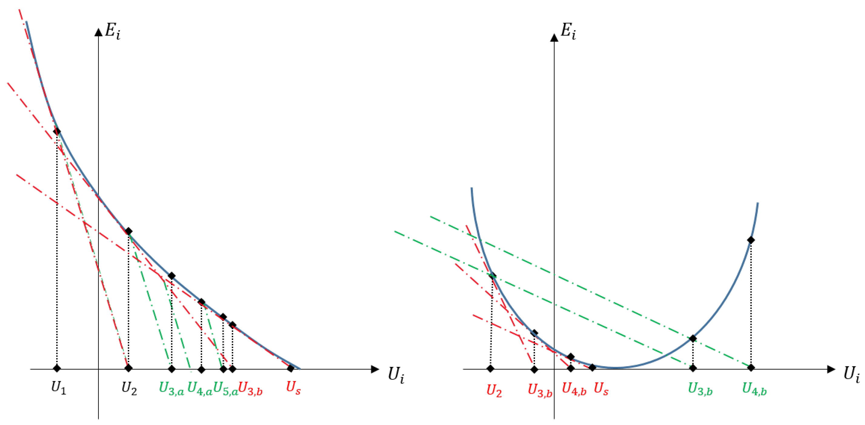
3.2. Convergence Condition
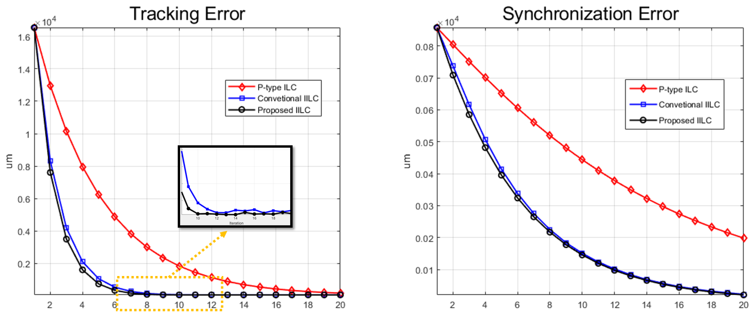
The convergence characteristics of the iterative learning is one of the critical functionalities. Based on the equations for convergence, the characteristics of the convergence speed of the present algorithm could be analyzed. The inversion-based ILC of Equation (5) is given as
Y i ω n = G i ω n U i ω n + N i ω n .
Without loss of generality, a target system can be expressed with
Y d ω n = G d ω n U d ω n .
The “iteration-varying” system is
G i ω n = G d ω n + δ G i ω n
where δ G i ω n represents the difference between the i-th system and the target system or variation in the system due to iteration. In addition, as the iteration number increases to infinity, the system for the i-th iteration asymptotically approaches the target system:
G i ω n G d ω n as i .
With these conditions, the convergence of the input error which is the difference between the i-th input and the target input can be defined as
δ U i ω n = U d ω n U i ω n .
For Equation (3), it can be rephrased as follows:
δ U i ω n = U d ω n U i 1 ω n α G ^ i 1 1 ω n E i 1 ω n = 1 α G ^ i 1 1 ω n G i 1 ω n δ U i 1 ω n α G ^ i 1 1 ω n G d ω n G i 1 ω n U d ω n + α G ^ i 1 1 ω n N i 1 ω n .
From Equations (8) and (9), the convergence condition for input error is
C i ω n = 1 α Δ G i ω n < 1 ω n
where Δ G i ω n = G ^ i 1 ω n G i ω n is the i-th iteration-varying model uncertainty.
From the above equations, it is possible to consider how convergence can vary depending on which variable. Two variables can affect the convergence performances, α and Δ G i in this equation. As a result, an analysis of the convergence characteristics regarding α and Δ G i could constitute a complete set of the analytical work. However, that is not the scope of this article. A well-coordinated study for the analysis on the convergence condition, especially reformulating the method for G ^ i 1 ω n at every iteration, would be one of the immediate follow-up tasks. Note that accurate estimation of the inverse model guarantees a better performance on both convergence and convergence speed.

4. Simulation

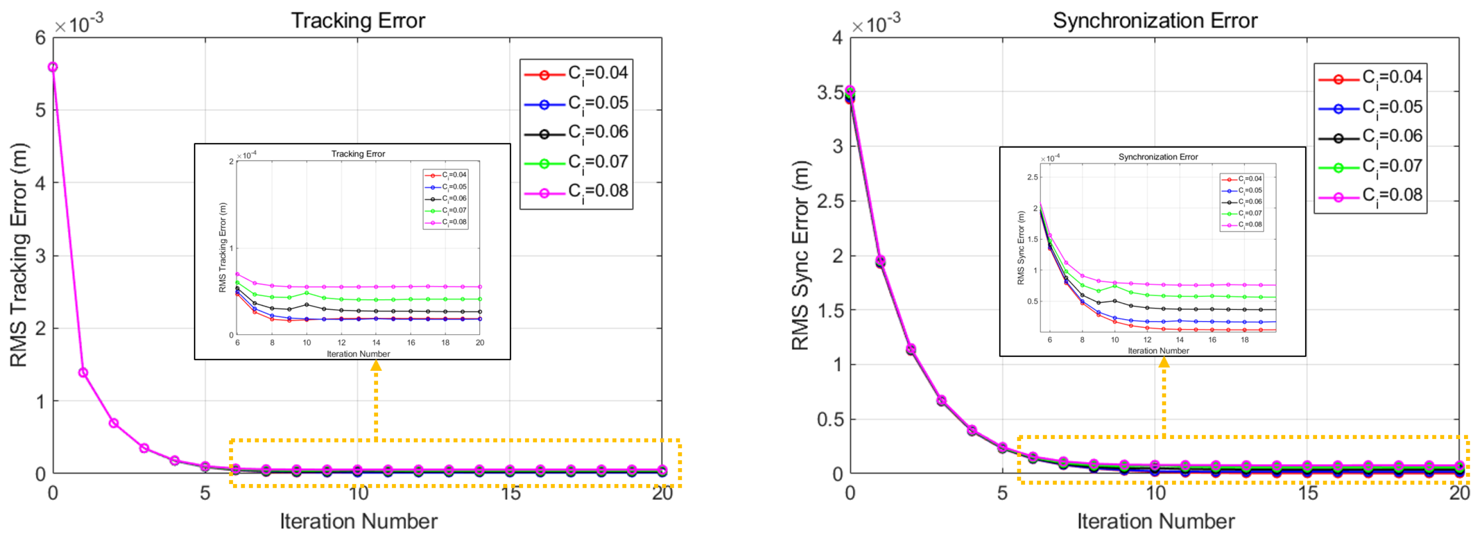
4.1. Dual-Drive System

To test the performance of the proposed algorithm, a set of simulations are designed based on a generic gantry mechanism shown in Figure 1. In order to test the IILC’s performance that is applied to a MIMO system, the mechanical coupling should be properly addressed in the simulation model. In other words, it is necessary to consider the factors causing synchronization errors in the plant. To represent the factors that cause synchronization errors, the following equation of motion is used:
M i y ¨ i + C i y ˙ i + K i δ y = F m , i
where M i denotes the mass for the i-axis, C i the friction parameter, K i the stiffness parameter, δ y the difference between axes, and F m , i the driving force. In a generic gantry structure, the friction and the bearing stiffness are the dominant sources of the synchronization error. In the shown mechanical system, the two axes cannot be perfectly assembled in parallel and might have some misalignment. This results in different friction and overall stiffness of the sliders, which were accounted for with C i and K i for each axis in Equation (13). The target motion is a sinusoidal wave function and checked with both target tracking and synchronization errors of two actuators. In Figure 4, it can be seen that both tracking error and synchronization error converge in a monotonic manner. For the convergence for various systems, simulations were performed by dividing the value of C i into several cases. Although there is a difference in the degree of convergence depending on the parameter value, it was confirmed that monotonic convergence was shown for all the performed cases.

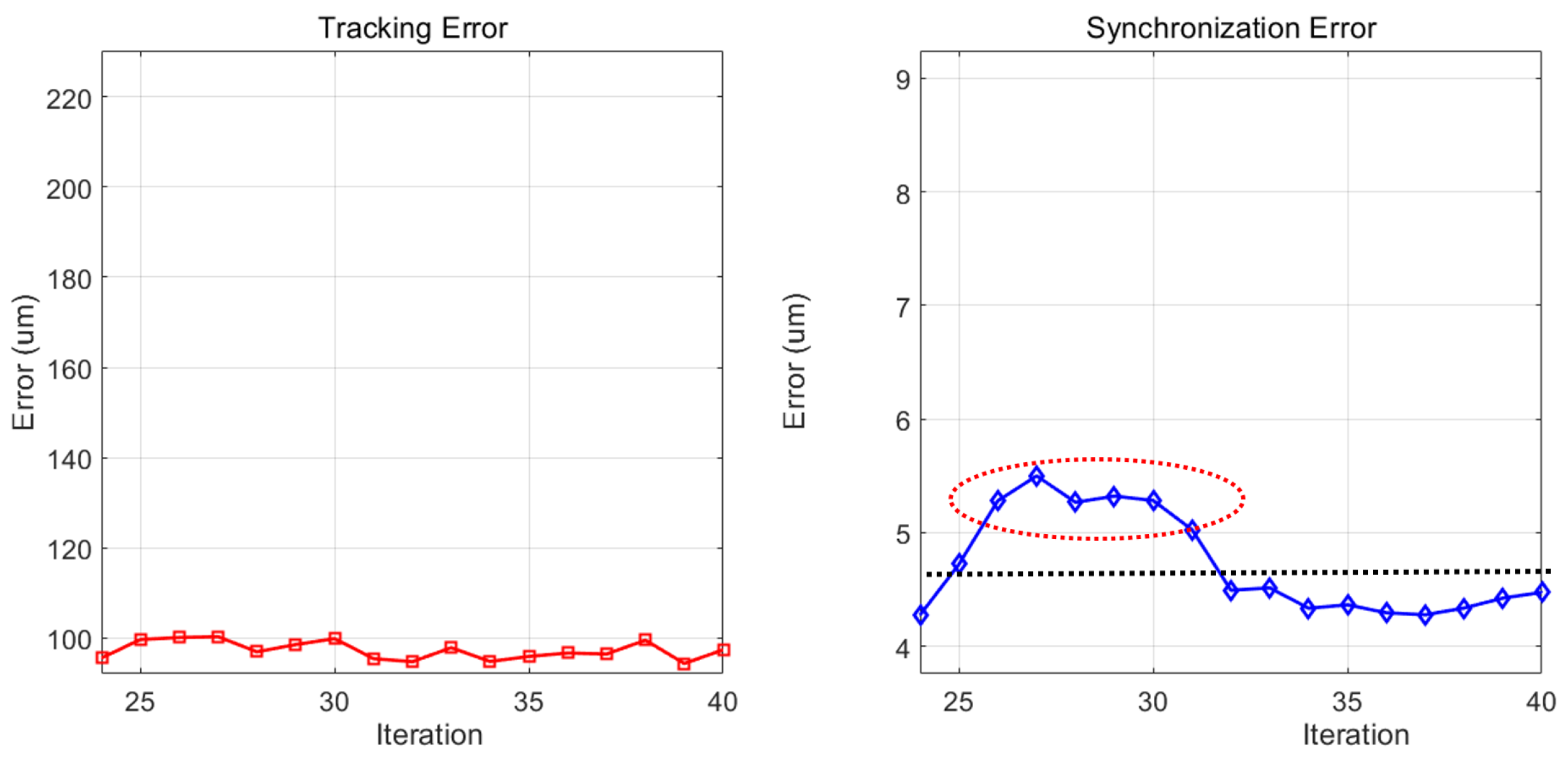
4.2. Iteration-Varying System
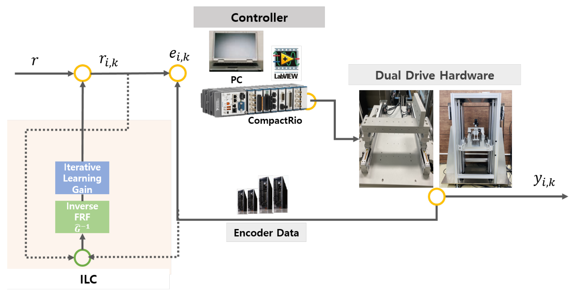
Recognizing that the MIMO system could be successfully controlled with the proposed method, the test, an iteration-varying system, is to be studied to verify the robustness. If the equipment is operated repeatedly, the system may change due to friction factors due to aging of parts or disturbance factors such as noise. It is necessary to check whether the proposed method shows robustness for a system that can change as iteration increases.
To implement the iteration-varying system, the friction and the stiffness values are changed as the iteration proceeds. In this simulation, when the iteration is at six, the disturbance is injected.
As shown in Figure 5, as soon as the noise is injected at the seventh iteration, the system is shaken. However, it regained its stable convergence very fast.

5. Experiment

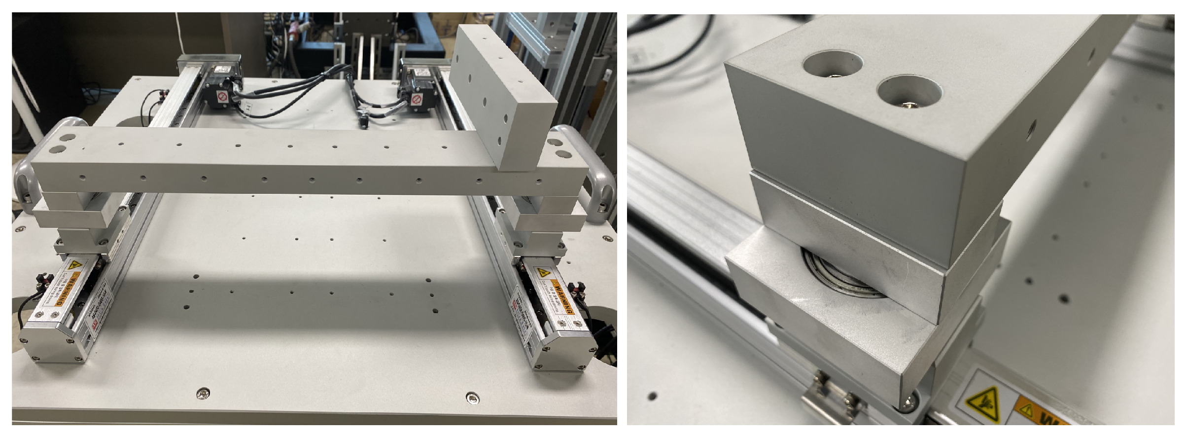
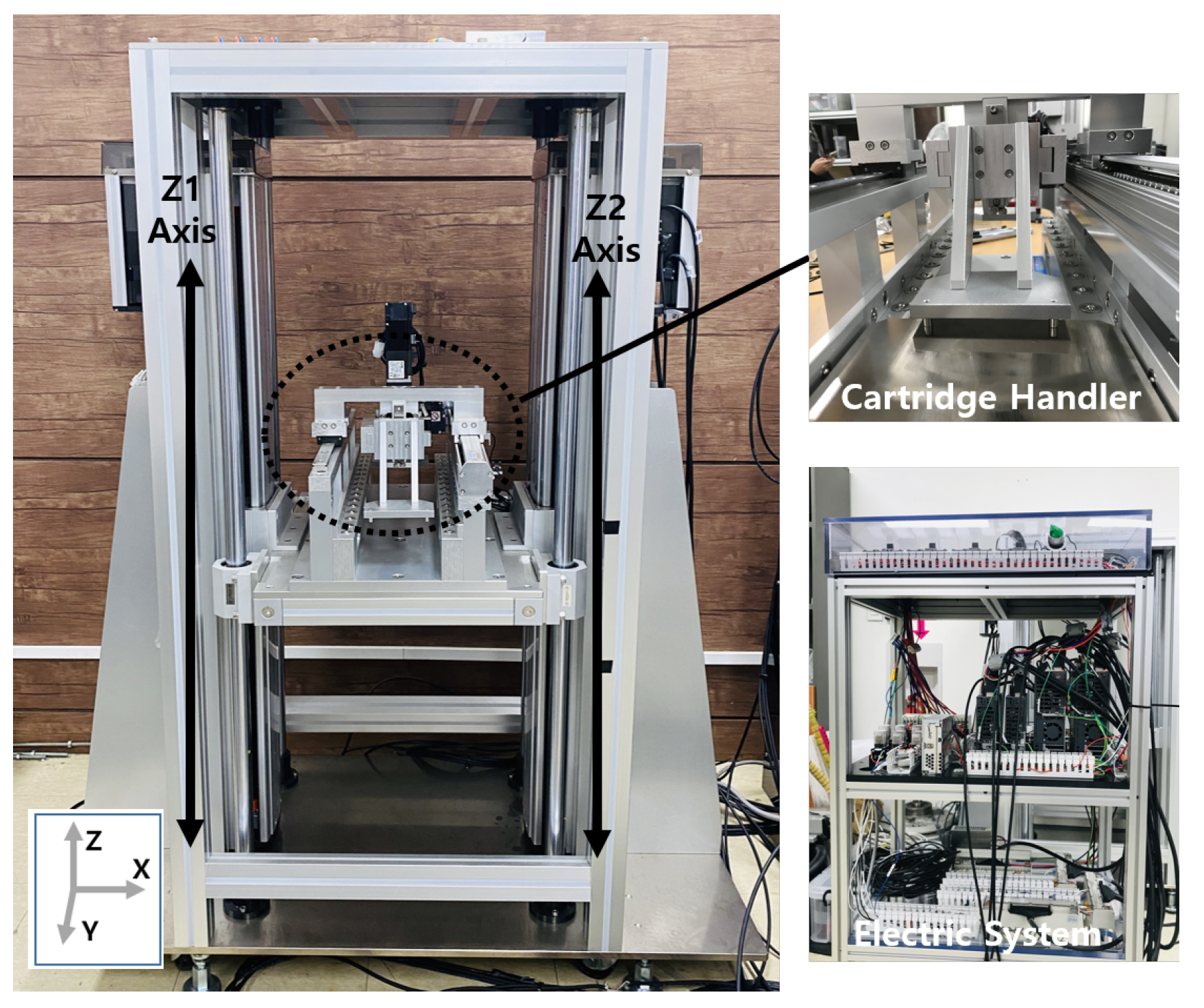
5.1. Experiment Setup

To test the performance of the proposed control algorithm, two systems were used. A generic dual-actuator gantry was built for preliminary tests of the present work. Then, the method was applied to a multi-probe wafer inspection cartridge transport robotic system which is driven with a pair of actuators. The gantry testbed is shown in Figure 6. Three experiments were conducted using this test setup. First, an experiment to verify the controller’s primitive performances on the dual-drive mechanism was conducted. This might be a basic test to confirm the paralleled SISO iterative learning controls when applied to a dual-motor system. Second, as shown in the simulation, the system parameters were changed while the iteration proceeded. The convergence performance of the designed method should be checked, and its steady-state error is to be verified. Lastly, to check its limitation, a challenging test setup that aggravates the mechanical coupling of the two actuators was built, and the proposed method was applied. Finally, the method was applied to a multi-probe wafer cartridge transportation system and its control accuracy was checked. The hardware for the experiment was configured as shown in Figure 7.

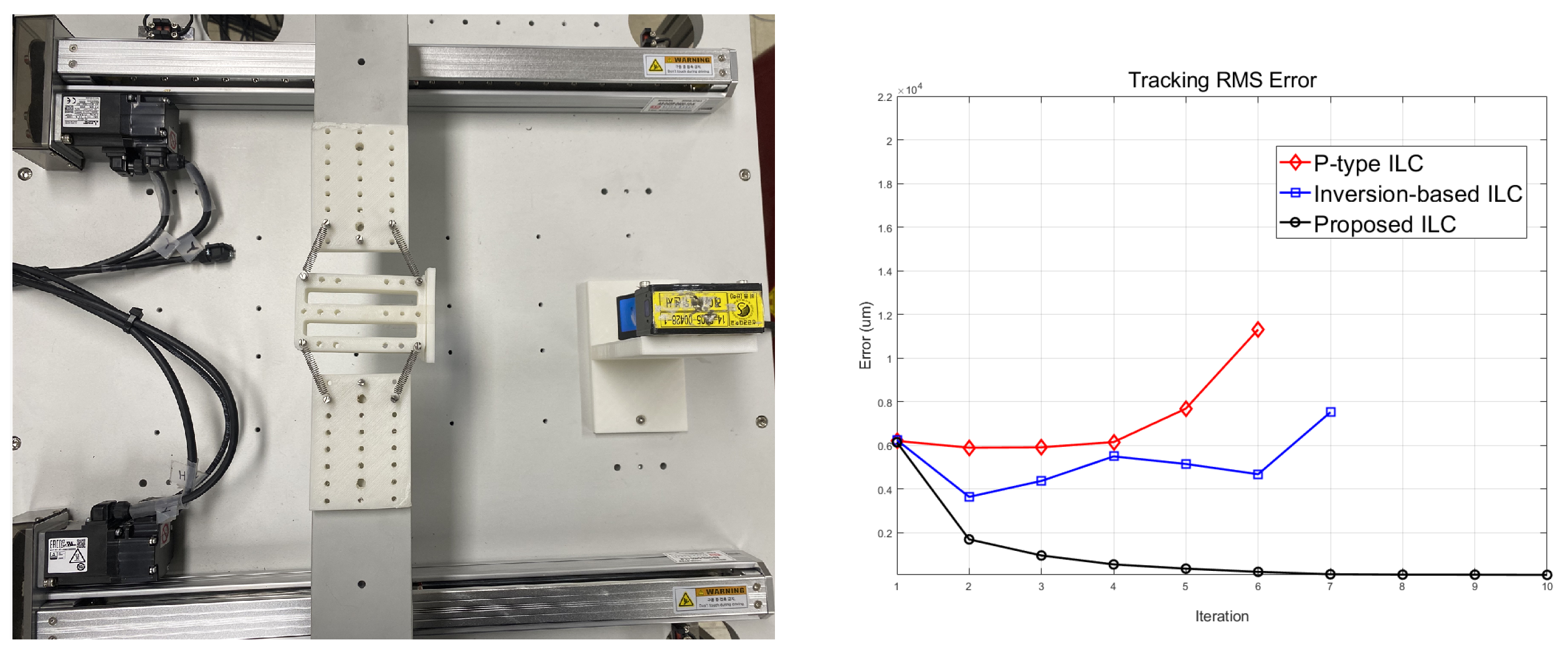
5.2. Dual-Actuator Gantry

Experiments were designed and conducted by configuring some different synchronization scenarios through the testbed. A rotating bearing was added between each drive shaft and the connecting bridge to increase the difficulty of the synchronization. Three experiments were conducted. First, the proposed method was compared with other ILCs for the synchronization error and tracking accuracy. Second, the robustness of the method was tested by injecting disturbance into an axis while it was learning. Lastly, the connecting bridge was modified for increased structural complexity by adding more degrees of freedom and vibration that might hamper the tracking accuracy.

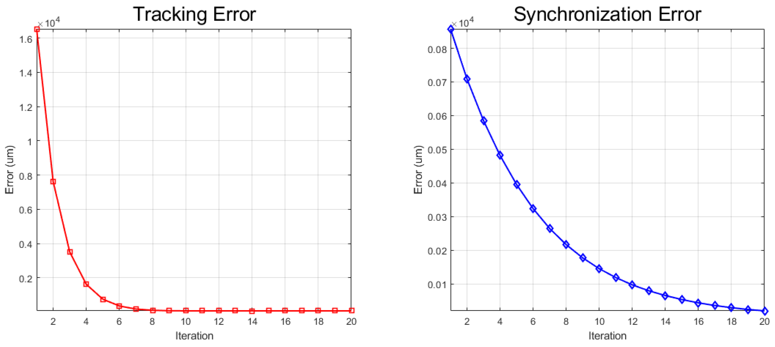
5.2.1. Basic Controller Performance Test

First, an experiment was conducted to verify the performance of the proposed algorithm. The reference position for tested target was a sinusoidal function which is in 0.5 Hz.
From Figure 8, it can be confirmed that the RMS error converges monotonically for tracking and synchronization. The proposed inverse model shows superior convergence speed and accuracy compared to other methods. When the number of iterations is 5–6 times, the tracking error has already reached the steady state, and the synchronization error also approaches small values. Even when comparing the results by applying other existing ILC algorithms, it can be confirmed through Figure 9 that the proposed method shows better convergence. The conventional IILC also shows fast convergence speed with reasonably acceptable accuracy. However, it can be seen that the performance is worse than the proposed algorithm since it has limitations for handling the iteration-varying factors such as time-dependent friction. In the case of P-type ILC, it is clearly seen that the convergence speed is slow with worse accuracy.

5.2.2. Iteration-Varying Test

In this experiment, to confirm the algorithm’s robustness, the driven mass is suddenly changed after the learning iteration converges. When a 30 kg additional weight is loaded on the connecting bridge, the tracking and synchronization errors are monitored in the test. Test results are shown in Figure 10. The synchronization error fluctuates as soon as the additional weight is added, although it soon becomes stable within a few iterations. The system change in the converged state can also be reflected in the next iteration through the model update method for each iteration. Accordingly, it was confirmed that the proposed method is robustly applicable to the iteration-varying system.

5.2.3. Robustness on Nonlinearity

As shown in Figure 11, to make the physical situation worse, the connecting bridge is cut, and a soft mechanism is inserted to connect the divided bridge. Note that tracking the target position with the modified plant becomes much more difficult due to the added flexible coupling mechanism. As shown in the figure, the bridge is divided and the spring-connected middle part is inserted. Its tracking motion is monitored with a laser displacement sensor. It can be confirmed that convergence is guaranteed with the proposed algorithm. In Figure 11, the tracking error is converged. Compared to others, the present work shows much better performances. RMS errors for the conventional P-type ILC and IILC diverge because the added mechanism makes the system nonlinear. In comparison, conventional algorithms fail to work in the nonlinear system.

5.3. Multi-Probe Wafer-Inspection System

Previously, various experiments were performed using a testbed to verify the proposed algorithm. The results confirmed that the performance was better than other methods, even for the complicated synchronization tracking tasks. This paper intends to control the industrial equipment that transports a heavy-weight multi-probe cartridge in a wafer inspection system. The configuration of the experiment environment is the same as the previous experiment, and the hardware is shown in Figure 12. When applied to the semiconductor wafer transport robot system, it can be seen that the present method works well for both the tracking and the synchronization, as shown in Figure 13.
Figure 14 shows time-domain data of the position tracking and the synchronization at the 20th iteration. In the case of synchronization error, it can be confirmed that the maximum error is within 10 um. In addition, the comparative study of RMS errors is showed in Figure 15. The proposed ILC provides superior RMS errors for both tracking and synchronization. It also confirms that the proposed method, a parallel SISO IILC controller, works well for the multi-actuator synchronization problems. Although this paper tries to prove that the parallel SISO IILC control works well for the multi-actuator system, it has been verified with limited physical systems consisting of linear motions. However, it is believed that few differences should be discovered when applied to multi-motor rotary motion machines in heavy payload operations.

6. Conclusions

This work tries to control a dual-actuator-driven system with a set of parallel SISO IILC controllers. Prior to constructing the actual controller, an IILC was addressed for the tracking and synchronization problems. In addition, this work confirms that the reformulation of the inversion model at each iteration improves the tracking error caused by iteration-varying or nonlinear system parameters. The present work involved carrying out simulations for the IILC controllers and a series of testings, including wafer testing systems. Although the method shows superior performances with good accuracies, it might have limitations. In other words, a set of SISO iterative learning controllers could not be a universal substitute for MIMO problems. Note that the problems presented in this work are defined with predefined repetitive target motions. However, this does not limit the technical contribution of this work since this work has successfully demonstrated its superiority for iteration-varying or nonlinear situations. In summary, this work shows its potential for accurate control of multi-actuator-driven systems with relatively simple architecture.

Author Contributions

Conceptualization, D.J.O. and J.C.K.; Data curation, D.J.O.; Formal analysis, D.J.O. and J.C.K.; Investigation, K.-T.N.; Methodology, D.J.O. and S.G.B.; Supervision, J.C.K.; Writing—original draft, D.J.O.; Writing—review & editing, J.C.K. All authors have read and agreed to the published version of the manuscript.

Funding

This work was supported by the National Research Foundation of Korea (NRF) grant funded by the Korean government (MSIT) (No. NRF-2020R1A2C2011450).

Conflicts of Interest

The authors declared no potential conflicts of interest with respect to the research, authorship, and/or publication of this article.

References

  1. Chen, C.-S.; Chen, L.-Y. Robust cross-coupling synchronous control by shaping position commands in multiaxes system. IEEE Trans. Ind. Electron. 2012, 59, 4761–4773. [Google Scholar] [CrossRef]
  2. Li, L.-B.; Sun, L.-L.; Zhang, S.-Z.; Yang, Q.-Q. Speed tracking and synchronization of multiple motors using ring coupling control and adaptive sliding mode control. ISA Trans. 2015, 58, 635–649. [Google Scholar] [CrossRef]
  3. Nam, K.T.; Lee, S.M.; Lee, S.J.; Lee, K.H.; Choo, S.W. Substrate Testing Cartridge and Method for Manufacturing Same. U.S. Patent Application No. 16/652174, 6 August 2020. [Google Scholar]
  4. Genkin, V.V.; Pronin, A.N.; Peters, J.A. Probe Card System for Testing an Integrated Circuit. U.S. Patent No. 11002761, 11 May 2021. [Google Scholar]
  5. Kamaldin, N.; Chen, S.L.; Teo, C.S.; Lin, W.; Tan, K.K. A novel adaptive jerk control with application to large workspace tracking on a flexure-linked dual-drive gantry. IEEE Trans. Ind. Electron. 2019, 66, 5353–5363. [Google Scholar] [CrossRef]
  6. Lorenz, R.D.; Schmidt, P.B. Synchronized motion control for process automation. In Proceedings of the Conference Record of the IEEE Industry Applications Society Annual Meeting, San Diego, CA, USA, 1–5 October 1989; pp. 1693–1698. [Google Scholar]
  7. Mori, T.; Hiramatsu, T.; Shamoto, E. Simultaneous double-sided milling of flexible plates with high accuracy and high efficiency—Suppression of forced chatter vibration with synchronized single-tooth cutters. Precis. Eng. 2011, 35, 416–423. [Google Scholar] [CrossRef]
  8. Wang, S.-M.; Wang, R.-J.; Tsooj, S. A new synchronous error control method for cnc machine tools with dual-driving systems. Int. J. Precis. Eng. Manuf. 2013, 14, 1415–1419. [Google Scholar] [CrossRef]
  9. Chen, S.-L.; Lin, W.; Chang, T. Tracking control for a synchronized dual parallel linear motor machine tool. Proc. Inst. Mech. Eng. Part I J. Syst. Control Eng. 2008, 222, 851–862. [Google Scholar] [CrossRef]
  10. Kim, S.; Chu, B.; Hong, D.; Park, H.-K.; Park, J.-M.; Cho, T.-Y. Synchronizing dual-drive gantry of chip mounter with lqr approach. In Proceedings of the 2003 IEEE/ASME International Conference on Advanced Intelligent Mechatronics (AIM 2003), Kobe, Japan, 20–24 July 2003; Volume 2, pp. 838–843. [Google Scholar]
  11. Tsai, M.-C.; Shen, B.-H. Synchronisation control of parallel dual inverted pendulums driven by linear servomotors. IET Control Theory Appl. 2008, 1, 320–327. [Google Scholar] [CrossRef]
  12. Ishizaki, K.; Sencer, B.; Shamoto, E. Cross coupling controller for accurate motion synchronization of dual servo systems. IJAT 2013, 7, 514–522. [Google Scholar] [CrossRef]
  13. Wang, M.; Ren, X.; Chen, Q. Cascade optimal control for tracking and synchronization of a multimotor driving system. IEEE Trans. Control Syst. Technol. 2018, 27, 1376–1384. [Google Scholar] [CrossRef]
  14. Lin, F.-J.; Chou, P.-H.; Chen, C.-S.; Lin, Y.-S. Dsp-based cross-coupled synchronous control for dual linear motors via intelligent complementary sliding mode control. IEEE Trans. Ind. Electron. 2011, 59, 1061–1073. [Google Scholar] [CrossRef]
  15. Wang, M.; Ren, X.; Chen, Q. Robust tracking and distributed synchronization control of a multi-motor servomechanism with h-infinity performance. ISA Trans. 2018, 72, 147–160. [Google Scholar] [CrossRef]
  16. Wang, T.; Ge, J.; Li, T.; Chen, X.; Fei, S. Observer-based h∞ control for synchronization in delayed neural networks under multiple disturbances. Int. J. Control Autom. Syst. 2020, 18, 3121–3132. [Google Scholar] [CrossRef]
  17. Zhao, W.; Ren, X.; Wang, S. Parameter estimation-based time-varying sliding mode control for multimotor driving servo systems. IEEE/ASME Trans. Mechatron. 2017, 22, 2330–2341. [Google Scholar] [CrossRef]
  18. Kuang, Z.; Gao, H.; Tomizuka, M. Precise linear-motor synchronization control via cross-coupled second-order discrete-time fractional-order sliding mode. IEEE/ASME Trans. Mechatron. 2021, 26, 358–368. [Google Scholar] [CrossRef]
  19. Huang, J.; Zhang, J.; Huang, W.; Yin, C. Optimal speed synchronization control with disturbance compensation for an integrated motor-transmission powertrain system. J. Dyn. Syst. Meas. Control 2019, 141, 041001. [Google Scholar] [CrossRef]
  20. Li, C.; Yao, B.; Wang, Q. Modeling and synchronization control of a dual drive industrial gantry stage. IEEE/ASME Trans. Mechatron. 2018, 23, 2940–2951. [Google Scholar] [CrossRef]
  21. Li, C.; Chen, Z.; Yao, B. Advanced synchronization control of a dual-linear-motor-driven gantry with rotational dynamics. IEEE Trans. Ind. Electron. 2018, 65, 7526–7535. [Google Scholar] [CrossRef]
  22. Li, C.; Chen, Z.; Yao, B. Adaptive thrust allocation based synchronization control of a dual drive gantry stage. Mechatronics 2018, 54, 68–77. [Google Scholar] [CrossRef]
  23. Longman, R.W. Iterative learning control and repetitive control for engineering practice. Int. J. Control 2000, 73, 930–954. [Google Scholar] [CrossRef]
  24. Tayebi, A. Adaptive iterative learning control for robot manipulators. Automatica 2004, 40, 1195–1203. [Google Scholar] [CrossRef]
  25. Mishra, S.; Coaplen, J.; Tomizuka, M. Precision positioning of wafer scanners segmented iterative learning control for nonrepetitive disturbances [applications of control]. IEEE Control Syst. Mag. 2007, 27, 20–25. [Google Scholar]
  26. Chien, C.-J.; Liu, J.-S. A p-type iterative learning controller for robust output tracking of nonlinear time-varying systems. Int. J. Control 1996, 64, 319–334. [Google Scholar] [CrossRef]
  27. Gu, P.; Tian, S. P-type iterative learning control with initial state learning for one-sided lipschitz nonlinear systems. Int. J. Control Autom. Syst. 2019, 17, 2203–2210. [Google Scholar] [CrossRef]
  28. Smolders, K.; Volckaert, M.; Swevers, J. Tracking control of nonlinear lumped mechanical continuous-time systems: A model-based iterative learning approach. Mech. Syst. Signal Process. 2008, 22, 1896–1916. [Google Scholar] [CrossRef]
  29. van Zundert, J.; Oomen, T. On inversion-based approaches for feedforward and ILC. Mechatronics 2018, 50, 282–291. [Google Scholar] [CrossRef] [Green Version]
  30. Yoon, D.; Ge, X.; Okwudire, C.E. Optimal inversion-based iterative learning control for overactuated systems. IEEE Trans. Control Syst. Technol. 2019, 28, 1948–1955. [Google Scholar] [CrossRef]
  31. Kim, K.-S.; Zou, Q. A modeling-free inversion-based iterative feedforward control for precision output tracking of linear time-invariant systems. IEEE/ASME Trans. Mechatron. 2012, 18, 1767–1777. [Google Scholar] [CrossRef]
  32. Cornelis, B.; Toso, A.; Verpoest, W.; Peeters, B. Improved mimo frf estimation and model updating for robust time waveform replication on durability test rigs. Int. Conf. Noise Vib. Eng. 2014, 1, 759–774. [Google Scholar]
  33. Huang, C.-C.; Chen, H.-C.; Huang, K.-W.; Fu, L.-C. Iterative Learning Controller with Learning Gain Optimization and Online Data Adjustment for Atomic Force Microscope. In Proceedings of the 2020 International Automatic Control Conference (CACS), Hsinchu, Taiwan, 4–7 November 2020; pp. 1–6. [Google Scholar]
Figure 1. Schematics of multi-actuator-driven gantry. (a) Linear motion system. (b) Rotational motion system.
Electronics 10 02904 g001
Figure 2. Model update in Newton method.
Electronics 10 02904 g002
Figure 3. Block diagram for inversion-based IILC.
Electronics 10 02904 g003
Figure 4. Simulation result for IILC.
Electronics 10 02904 g004
Figure 5. Iteration-varying system convergence.
Electronics 10 02904 g005
Figure 6. A dual-actuator gantry testbed.
Electronics 10 02904 g006
Figure 7. Control system configuration.
Electronics 10 02904 g007
Figure 8. RMS error for tracking and synchronizing with gantry type testbed.
Electronics 10 02904 g008
Figure 9. Track and synchronization with ILC algorithms.
Electronics 10 02904 g009
Figure 10. Robustness test for varying system in gantry type testbed.
Electronics 10 02904 g010
Figure 11. Modified connecting bridge for low stiffness.
Electronics 10 02904 g011
Figure 12. Cartridge transport robot in multi-probe wafer-inspection system.
Electronics 10 02904 g012
Figure 13. Tracking and synchronization errors.
Electronics 10 02904 g013
Figure 14. Tracking and synchronization in time domain.
Electronics 10 02904 g014
Figure 15. Comparison for tracking and synchronization error in each system.
Electronics 10 02904 g015
Publisher’s Note: MDPI stays neutral with regard to jurisdictional claims in published maps and institutional affiliations.

