
Optimal Control of Centralized Thermoelectric Generation System under Nonuniform Temperature Distribution Using Barnacles Mating Optimization Algorithm


Abstract
:1. Introduction
- We proposed an MPPT technique that requires less iteration to track the GM with only one tuning parameter. The proposed MPPT technique can effectively track GM under NTD with high efficiency and reduce power loss.
- The implementation complexity of the proposed technique is very low and can be implemented on a low-cost controller. Results of multiple cases demonstrate the superiority of the BMO techniques in terms of fast tracking and quick settling at GM.
2. Modeling of TEG System
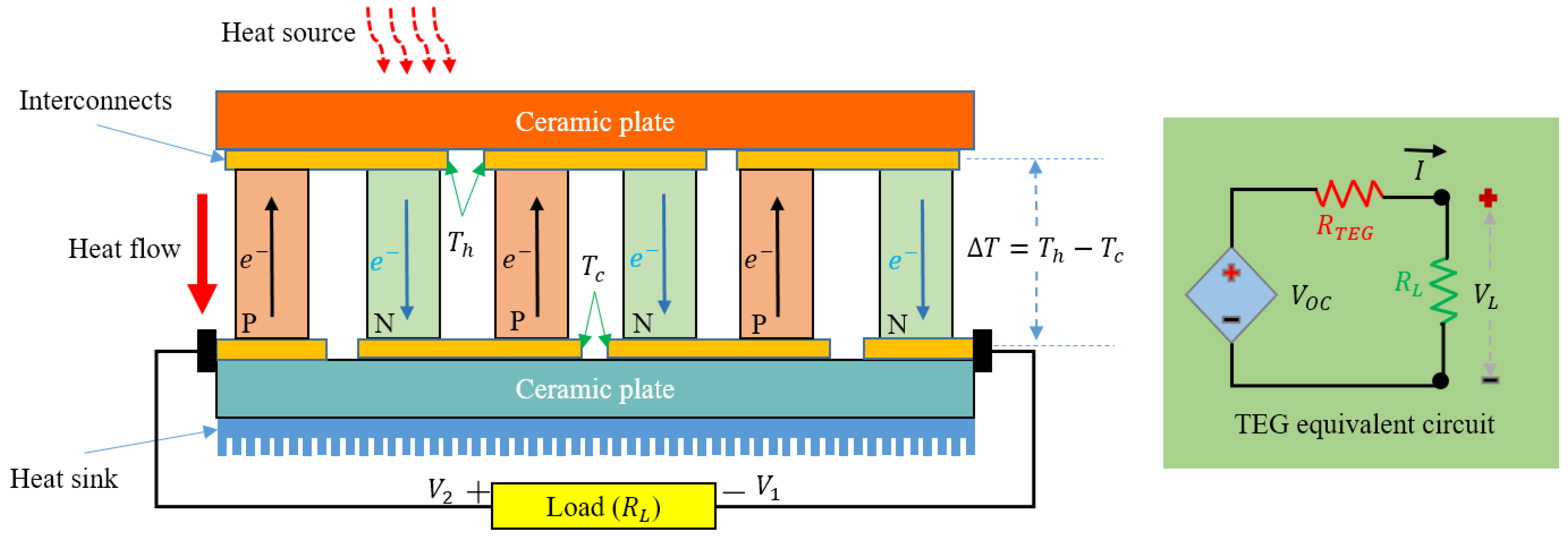
2.1. TEG Module Modeling
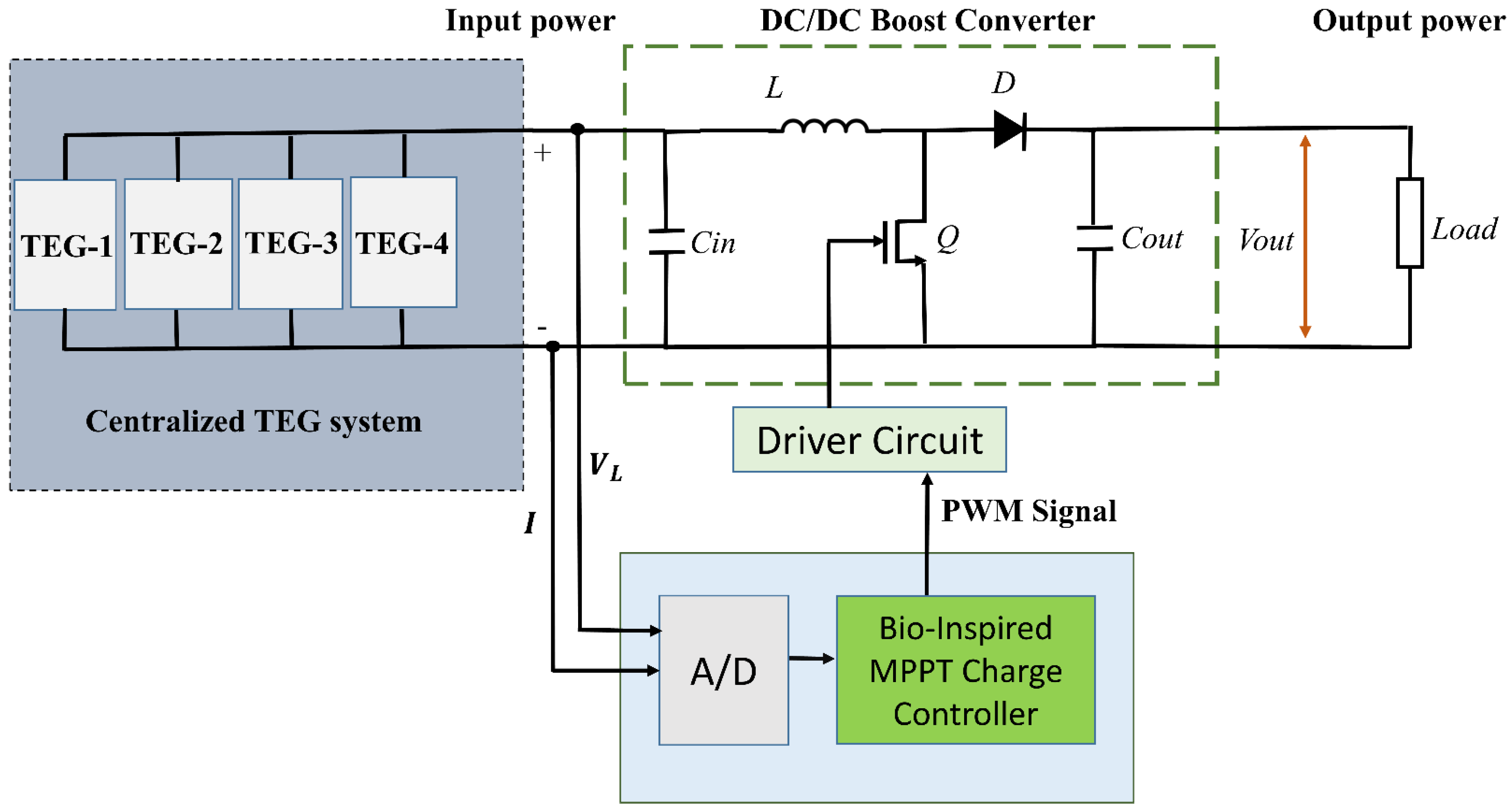
2.2. Configuration of TEG System
2.3. Modeling of TEG System under NTD Condition
3. Proposed Technique
3.1. Inspiration
3.2. Initialization
3.3. Selection Process
3.4. Re-Production
4. BMO-Based Control of TEG System
4.1. Control Variable
4.2. Fitness Function
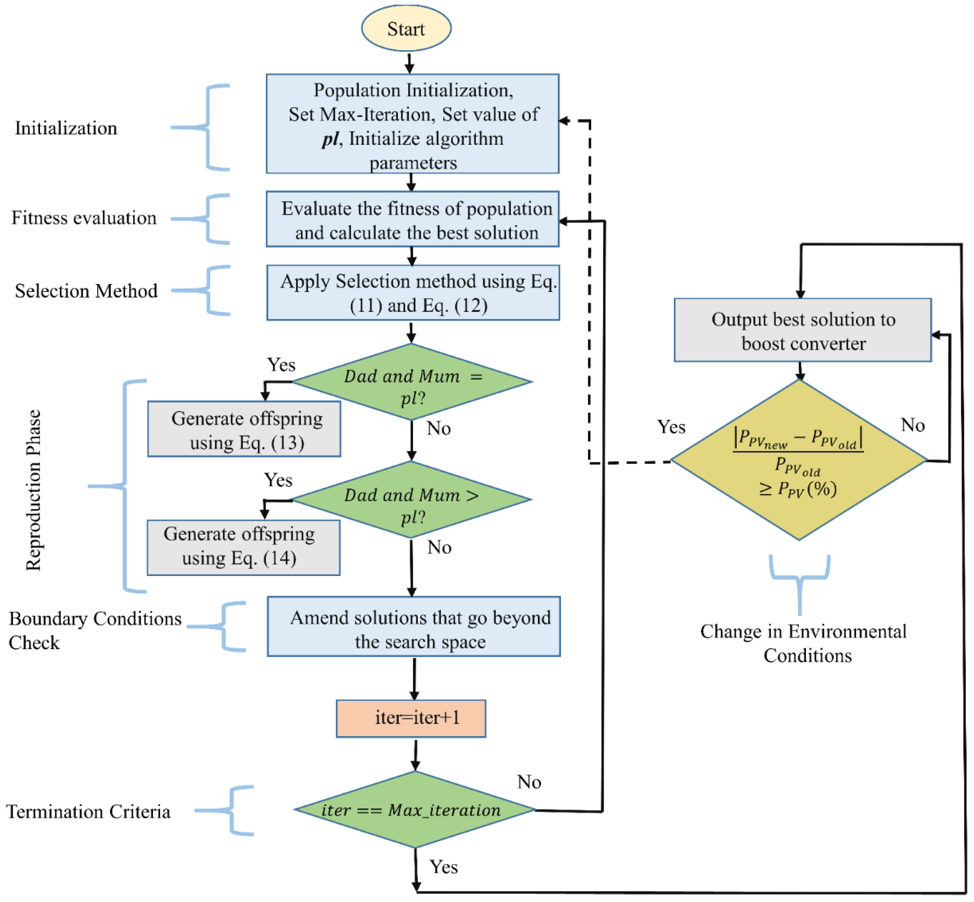
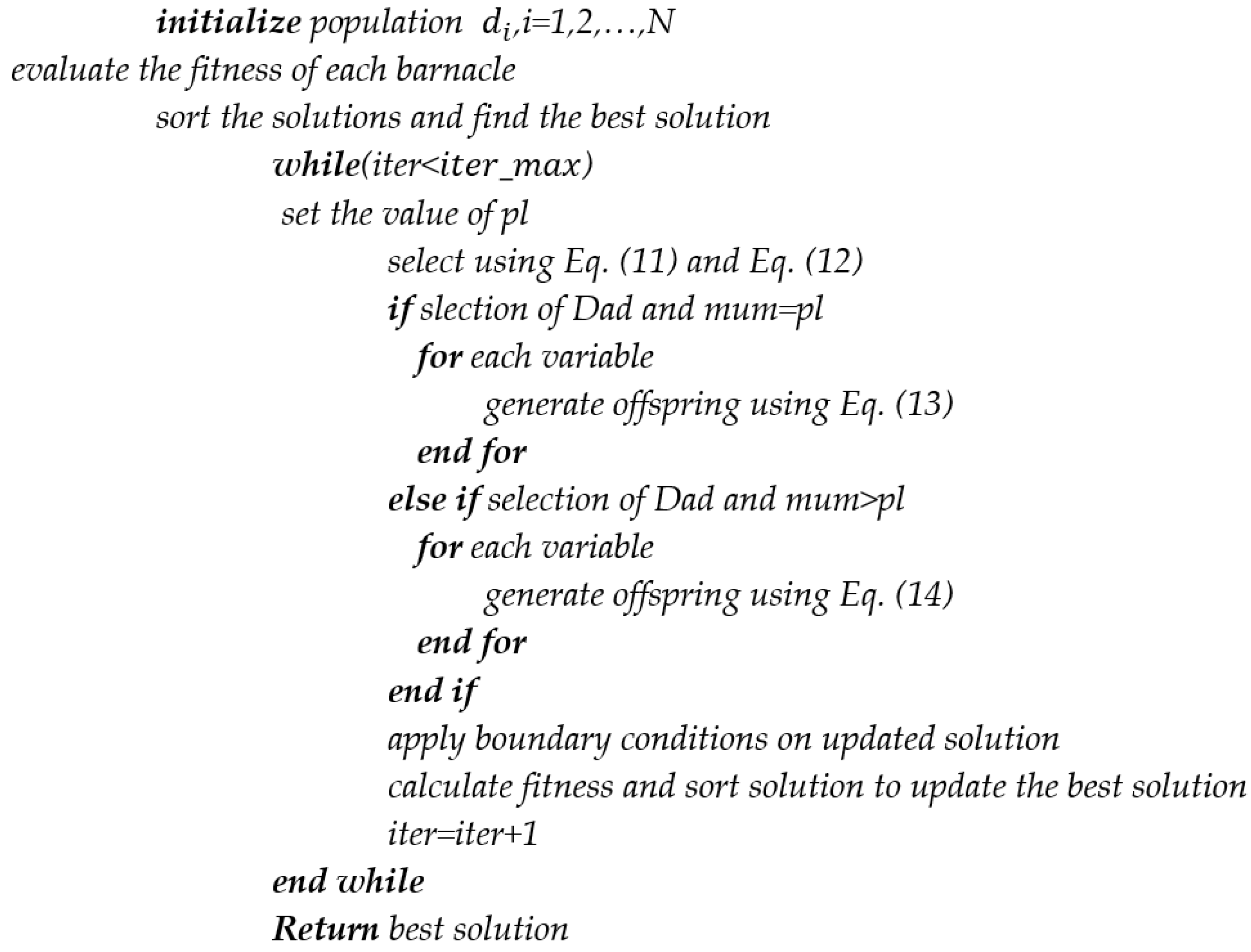
4.3. Execution Procedure
5. Case Studies
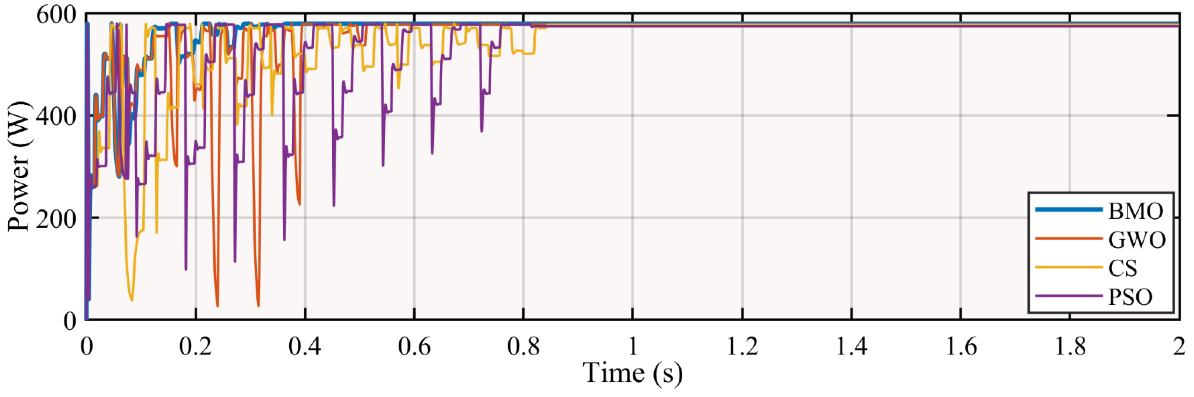
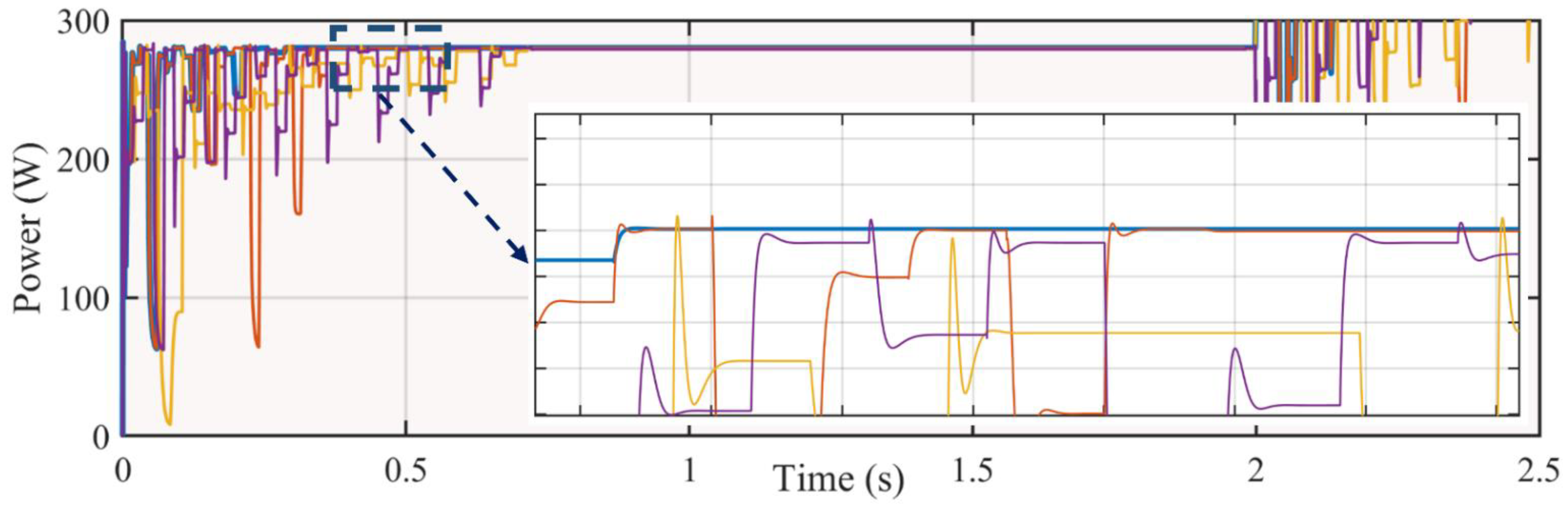
5.1. Startup Test
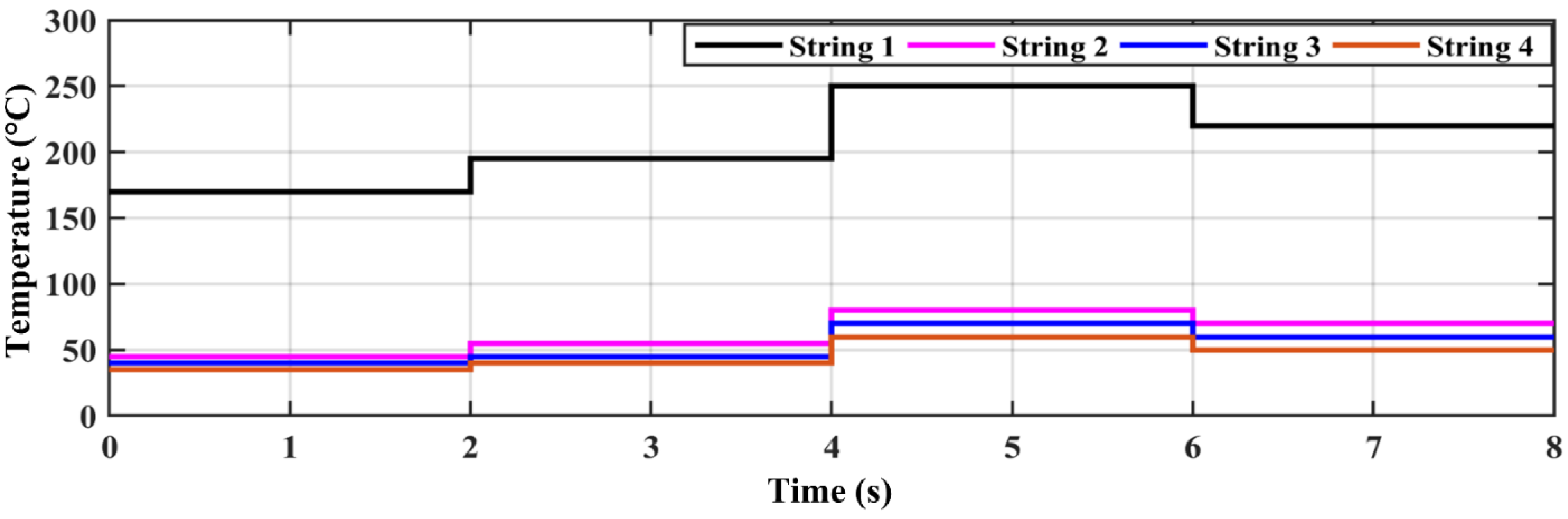
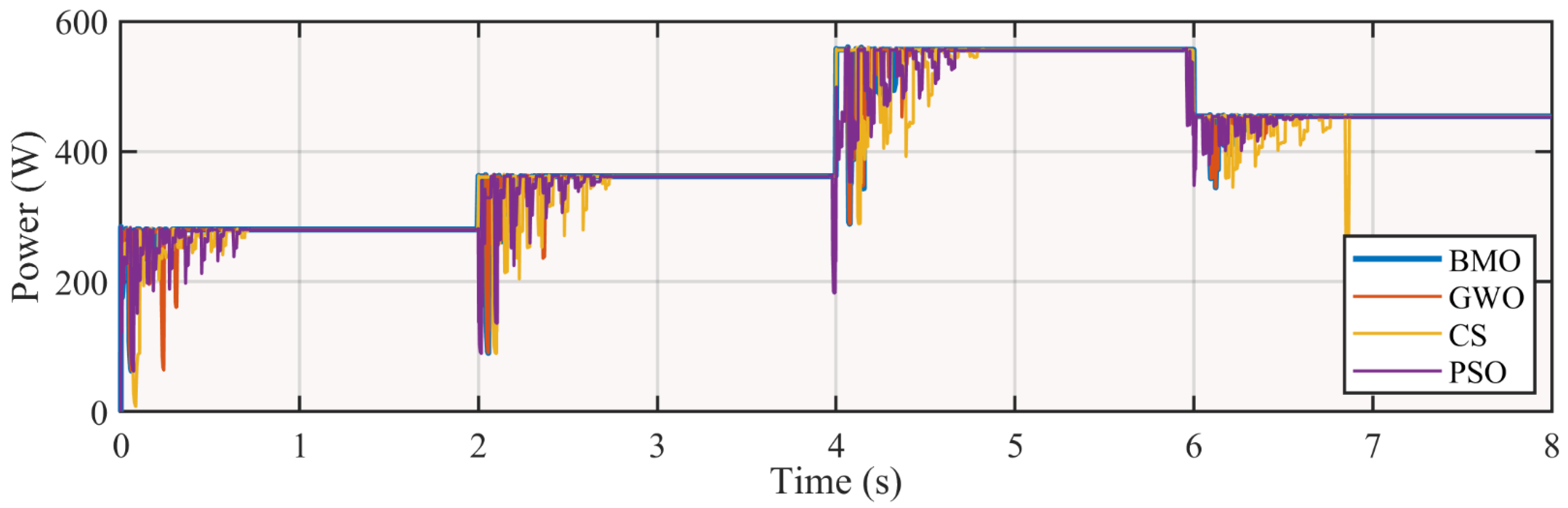
5.2. Fast-Changing Temperature
5.3. MPPT Rating
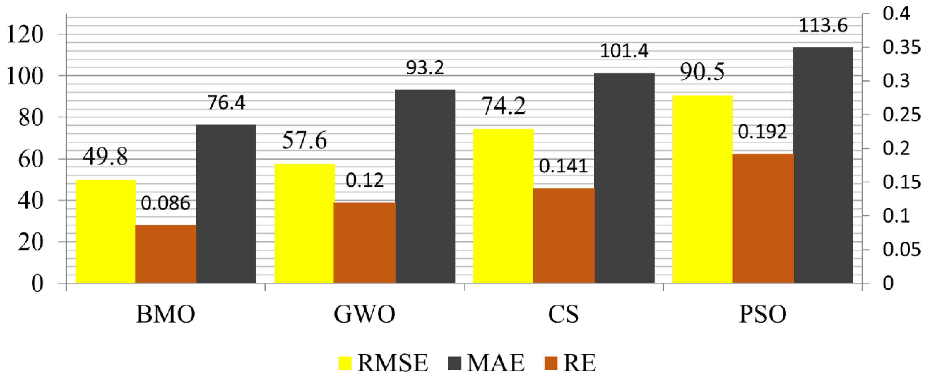
5.4. Statistical Analysis
5.5. Efficiency and Performance Evaluation
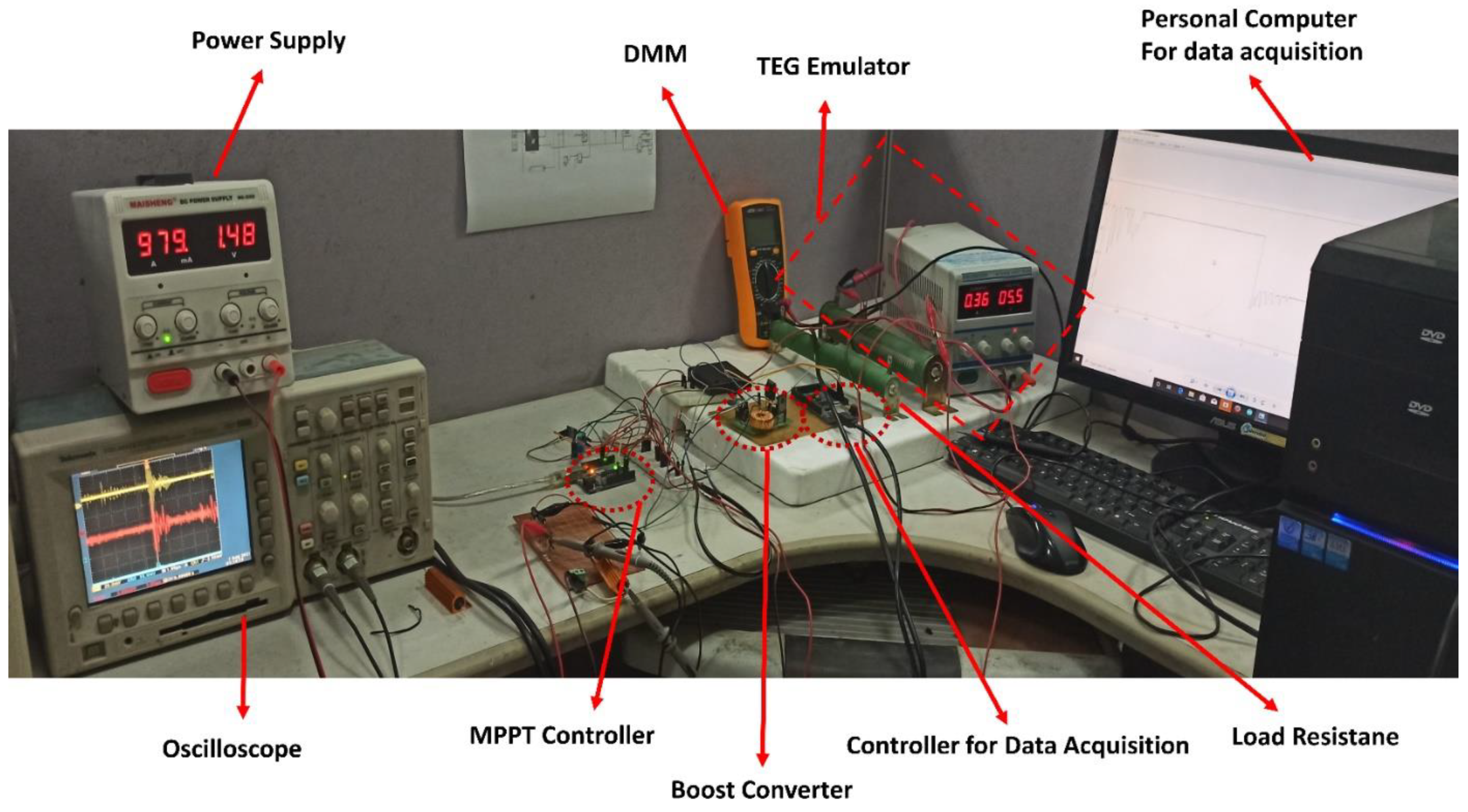
5.6. Hardware Verification
6. Conclusions
Author Contributions
Funding
Conflicts of Interest
References
- Karbaschi, H.; Nouri, N.; Rezaei, M.; Rashedi, G. Thermoelectric power generation efficiency of zigzag monolayer nanoribbon of bismuth. Nanotechnology 2020, 31, 375403. [Google Scholar] [CrossRef]
- Yuan, C.; Sadashivaiah, G.; Bechtold, T.; Rudnyi, E.B. Efficient Design Optimization of A Thermoelectric Generator by A Combination of Model Order Reduction and Thermal Submodeling Techniques. In Proceedings of the 33rd International ECMS Conference on Modelling and Simulation, ECMS 2019, Caserta, Italy, 11–14 June 2019. [Google Scholar]
- Eldesoukey, A.; Hassan, H. 3D model of thermoelectric generator (TEG) case study: Effect of flow regime on the TEG performance. Energy Convers. Manag. 2019, 180, 231–239. [Google Scholar] [CrossRef]
- Ballo, A.; Grasso, A.D.; Palumbo, G.; Tanzawa, T. Charge Pumps for Ultra-Low-Power Applications: Analysis, Design and New Solutions. IEEE Trans. Circuits Syst. II Express Briefs 2021, 68, 2895–2901. [Google Scholar] [CrossRef]
- Kumar, P.M.; Jagadeesh Babu, V.; Subramanian, A.; Bandla, A.; Thakor, N.; Ramakrishna, S.; Wei, H. The design of a thermoelectric generator and its medical applications. Designs 2019, 3, 22. [Google Scholar] [CrossRef] [Green Version]
- Leonov, V.; Torfs, T.; Fiorini, P.; Van Hoof, C. Thermoelectric converters of human warmth for self-powered wireless sensor nodes. IEEE Sens. J. 2007, 7, 650–657. [Google Scholar] [CrossRef]
- Zhang, H.; Yue, H.; Huang, J.; Liang, K.; Chen, H. Experimental Studies on a Low Concentrating Photovoltaic/Thermal (LCPV/T) Collector with a Thermoelectric Generator (TEG) Module. Renew. Energy 2021, 171, 1026–1044. [Google Scholar] [CrossRef]
- He, M.; Wang, E.; Zhao, C.; Zhang, F. Mathematical Modelling and Heat Transfer Performance of a TEG for Engine Exhaust Heat Recovery. J. Phys. Conf. Ser. 2020, 1624, 032002. [Google Scholar] [CrossRef]
- Liang, G.; Zhou, J.; Huang, X. Analytical model of parallel thermoelectric generator. Appl. Energy 2011, 88, 5193–5199. [Google Scholar] [CrossRef]
- Pachaivannan, N.; Subburam, R.; Padmanaban, M.; Subramanian, A. Certain investigations of ANFIS assisted CPHO algorithm tuned MPPT controller for PV arrays under partial shading conditions. J. Ambient. Intell. Humaniz. Comput. 2021, 12, 9923–9938. [Google Scholar] [CrossRef]
- Jegajothi, B.; Yaashuwanth, C. Generation of maximum power in PV system using EHO based embedded controller. J. Ambient. Intell. Humaniz. Comput. 2021, 12, 5161–5178. [Google Scholar] [CrossRef]
- Ballo, A.; Bottaro, M.; Grasso, A.D.; Palumbo, G. Regulated charge pumps: A comparative study by means of verilog-AMS. Electronics 2020, 9, 998. [Google Scholar] [CrossRef]
- Rodriguez, A.; Vazquez, A.; Rogina, M.R.; Briz, F. Synchronous boost converter with high efficiency at light load using QSW-ZVS and SiC MOSFETs. IEEE Trans. Ind. Electron. 2017, 65, 386–393. [Google Scholar] [CrossRef]
- Lan, S.; Yang, Z.; Stobart, R.; Chen, R. Prediction of the fuel economy potential for a skutterudite thermoelectric generator in light-duty vehicle applications. Appl. Energy 2018, 231, 68–79. [Google Scholar] [CrossRef]
- Jaziri, N.; Boughamoura, A.; Müller, J.; Mezghani, B.; Tounsi, F.; Ismail, M. A comprehensive review of Thermoelectric Generators: Technologies and common applications. Energy Rep. 2020, 6, 264–287. [Google Scholar] [CrossRef]
- Motiei, P.; Yaghoubi, M.; GoshtasbiRad, E. Transient simulation of a hybrid photovoltaic-thermoelectric system using a phase change material. Sustain. Energy Technol. Assess. 2019, 34, 200–213. [Google Scholar] [CrossRef]
- Ranjan, M.; Maiti, T. Device modeling and performance optimization of thermoelectric generators under isothermal and isoflux heat source condition. J. Power Sources 2020, 480, 228867. [Google Scholar] [CrossRef]
- Cai, Y.; Wang, W.-W.; Liu, C.-W.; Ding, W.-T.; Liu, D.; Zhao, F.-Y. Performance evaluation of a thermoelectric ventilation system driven by the concentrated photovoltaic thermoelectric generators for green building operations. Renew. Energy 2020, 147, 1565–1583. [Google Scholar] [CrossRef]
- Kumar, V.; Ghosh, S.; Naidu, N.S.; Kamal, S.; Saket, R.; Nagar, S. A current sensor based adaptive step-size MPPT with SEPIC converter for photovoltaic systems. IET Renew. Power Gener. 2021, 15, 1085–1099. [Google Scholar] [CrossRef]
- Verma, P.; Garg, R.; Mahajan, P. Asymmetrical interval type-2 fuzzy logic control based MPPT tuning for PV system under partial shading condition. ISA Trans. 2020, 100, 251–263. [Google Scholar] [CrossRef]
- Ma, L. Intelligent charging control method of shared vehicle based on MPPT algorithm in the environment of internet of things. J. Ambient. Intell. Humaniz. Comput. 2021, 1–9. [Google Scholar] [CrossRef]
- Aly, M.; Rezk, H. An improved fuzzy logic control-based MPPT method to enhance the performance of PEM fuel cell system. Neural Comput. Appl. 2021, 1–12. [Google Scholar] [CrossRef]
- Hong, C.-M.; Chen, C.-H. Enhanced radial fuzzy wavelet neural network with sliding mode control for a switched reluctance wind turbine distributed generation system. Eng. Optim. 2019, 51, 1133–1151. [Google Scholar] [CrossRef]
- Radosavljević, J.; Jevtić, M.; Klimenta, D. Energy and operation management of a microgrid using particle swarm optimization. Eng. Optim. 2016, 48, 811–830. [Google Scholar] [CrossRef]
- Zafar, M.H.; Al-shahrani, T.; Khan, N.M.; Feroz Mirza, A.; Mansoor, M.; Qadir, M.U.; Khan, M.I.; Naqvi, R.A. Group teaching optimization algorithm based MPPT control of PV systems under partial shading and complex partial shading. Electronics 2020, 9, 1962. [Google Scholar] [CrossRef]
- Mansoor, M.; Mirza, A.F.; Long, F.; Ling, Q. An Intelligent Tunicate Swarm Algorithm Based MPPT Control Strategy for Multiple Configurations of PV Systems Under Partial Shading Conditions. Adv. Theory Simul. 2021, 2100246. [Google Scholar] [CrossRef]
- Mansoor, M.; Mirza, A.F.; Duan, S.; Zhu, J.; Yin, B.; Ling, Q. Maximum energy harvesting of centralized thermoelectric power generation systems with non-uniform temperature distribution based on novel equilibrium optimizer. Energy Convers. Manag. 2021, 246, 114694. [Google Scholar] [CrossRef]
- Yedala, N.; Kaisare, N.S. Modeling of Thermal Integration of a Catalytic Microcombustor with a Thermoelectric for Power Generation Applications. Energy Fuels 2021, 35, 5141–5152. [Google Scholar] [CrossRef]
- Ming, T.; Yang, W.; Huang, X.; Wu, Y.; Li, X.; Liu, J. Analytical and numerical investigation on a new compact thermoelectric generator. Energy Convers. Manag. 2017, 132, 261–271. [Google Scholar] [CrossRef]
- Suja, K. Mitigation of power quality issues in smart grid using levy flight based moth flame optimization algorithm. J. Ambient. Intell. Humaniz. Comput. 2021, 12, 9209–9228. [Google Scholar] [CrossRef]
- Lee, U.; Park, S.; Lee, I. Robust design optimization (RDO) of thermoelectric generator system using non-dominated sorting genetic algorithm II (NSGA-II). Energy 2020, 196, 117090. [Google Scholar] [CrossRef]
- Eltamaly, A.M. A novel particle swarm optimization optimal control parameter determination strategy for maximum power point trackers of partially shaded photovoltaic systems. Eng. Optim. 2021, 1–17. [Google Scholar] [CrossRef]
- Mansoor, M.; Mirza, A.F.; Ling, Q. Harris hawk optimization-based MPPT control for PV Systems under Partial Shading Conditions. J. Clean. Prod. 2020, 274, 122857. [Google Scholar] [CrossRef]
- Ren, W.; Sun, Y.; Zhao, D.; Aili, A.; Zhang, S.; Shi, C.; Zhang, J.; Geng, H.; Zhang, J.; Zhang, L. High-performance wearable thermoelectric generator with self-healing, recycling, and Lego-like reconfiguring capabilities. Sci. Adv. 2021, 7, eabe0586. [Google Scholar] [CrossRef]
- Yang, B.; Zhang, M.; Zhang, X.; Wang, J.; Shu, H.; Li, S.; He, T.; Yang, L.; Yu, T. Fast atom search optimization based MPPT design of centralized thermoelectric generation system under heterogeneous temperature difference. J. Clean. Prod. 2020, 248, 119301. [Google Scholar] [CrossRef]
- Yang, B.; Wang, J.; Zhang, X.; Zhang, M.; Shu, H.; Li, S.; He, T.; Yang, L.; Yu, T. MPPT design of centralized thermoelectric generation system using adaptive compass search under non-uniform temperature distribution condition. Energy Convers. Manag. 2019, 199, 111991. [Google Scholar] [CrossRef]
- Liu, J.; Zhang, Y.; Zhang, D.; Jiao, S.; Zhang, Z.; Zhou, Z. Model development and performance evaluation of thermoelectric generator with radiative cooling heat sink. Energy Convers. Manag. 2020, 216, 112923. [Google Scholar] [CrossRef]
- Aly, M.; Rezk, H. A MPPT based on optimized FLC using manta ray foraging optimization algorithm for thermo-electric generation systems. Int. J. Energy Res. 2021. [Google Scholar] [CrossRef]
- Lv, S.; He, W.; Jiang, Q.; Hu, Z.; Liu, X.; Chen, H.; Liu, M. Study of different heat exchange technologies influence on the performance of thermoelectric generators. Energy Convers. Manag. 2018, 156, 167–177. [Google Scholar] [CrossRef]
- Zafar, M.H.; Khan, N.M.; Mirza, A.F.; Mansoor, M.; Akhtar, N.; Qadir, M.U.; Khan, N.A.; Moosavi, S.K.R. A novel meta-heuristic optimization algorithm based MPPT control technique for PV systems under complex partial shading condition. Sustain. Energy Technol. Assess. 2021, 47, 101367. [Google Scholar]
- Zafar, M.H.; Khan, N.M.; Mirza, A.F.; Mansoor, M. Bio-inspired optimization algorithms based maximum power point tracking technique for photovoltaic systems under partial shading and complex partial shading conditions. J. Clean. Prod. 2021, 309, 127279. [Google Scholar] [CrossRef]
- Kanimba, E.; Pearson, M.; Sharp, J.; Stokes, D.; Priya, S.; Tian, Z. A comprehensive model of a lead telluride thermoelectric generator. Energy 2018, 142, 813–821. [Google Scholar] [CrossRef]
- Mirza, A.F.; Mansoor, M.; Zhan, K.; Ling, Q. High-efficiency swarm intelligent maximum power point tracking control techniques for varying temperature and irradiance. Energy 2021, 228, 120602. [Google Scholar] [CrossRef]
- Kumar, S.; Heister, S.D.; Xu, X.; Salvador, J.R.; Meisner, G.P. Thermoelectric generators for automotive waste heat recovery systems part I: Numerical modeling and baseline model analysis. J. Electron. Mater. 2013, 42, 665–674. [Google Scholar] [CrossRef]
- Mirza, A.F.; Mansoor, M.; Ling, Q.; Yin, B.Q.; Javed, M.Y. A Salp-Swarm Optimization based MPPT technique for harvesting maximum energy from PV systems under partial shading conditions. Energy Convers. Manag. 2020, 209, 112625. [Google Scholar] [CrossRef]
- Mirza, A.F.; Mansoor, M.; Ling, Q. A novel MPPT technique based on Henry gas solubility optimization. Energy Convers. Manag. 2020, 225, 113409. [Google Scholar] [CrossRef]
- Mamur, H.; Coban, Y. Detailed modeling of a thermoelectric generator for maximum power point tracking. Turk. J. Electr. Eng. Comput. Sci. 2020, 28, 124–139. [Google Scholar] [CrossRef]
- Zheng, Y.; Zhang, Q.; Jin, W.; Jing, Y.; Chen, X.; Han, X.; Bao, Q.; Liu, Y.; Wang, X.; Wang, S. Carbon nanotube yarn based thermoelectric textiles for harvesting thermal energy and powering electronics. J. Mater. Chem. A 2020, 8, 2984–2994. [Google Scholar] [CrossRef]
- Yang, B.; Zhu, T.J.; Wang, J.B.; Shu, H.C.; Yu, T.; Zhang, X.S.; Yao, W.; Sun, L.M. Comprehensive overview of maximum power point tracking algorithms of PV systems under partial shading condition. J. Clean. Prod. 2020, 268, 121983. [Google Scholar] [CrossRef]
- Yadav, K.; Kumar, B.; Swaroop, D. Mitigation of mismatch power losses of PV array under partial shading condition using novel odd even configuration. Energy Rep. 2020, 6, 427–437. [Google Scholar] [CrossRef]
- Mirza, A.F.; Mansoor, M.; Zerbakht, K.; Javed, M.Y.; Zafar, M.H.; Khan, N.M. High-efficiency hybrid PV-TEG system with intelligent control to harvest maximum energy under various non-static operating conditions. J. Clean. Prod. 2021, 320, 128643. [Google Scholar] [CrossRef]
- Khan, N.M.; Khan, U.A.; Zafar, M.H. Maximum Power Point Tracking of PV System under Uniform Irradiance and Partial Shading Conditions using Machine Learning Algorithm Trained by Sailfish Optimizer. In Proceedings of the 2021 4th International Conference on Energy Conservation and Efficiency (ICECE), Lahore, Pakistan, 16–17 March 2021; pp. 1–6. [Google Scholar]
- Zafar, M.H.; Khan, U.A.; Khan, N.M. Hybrid Grey Wolf Optimizer Sine Cosine Algorithm based Maximum Power Point Tracking Control of PV Systems under Uniform Irradiance and Partial Shading Condition. In Proceedings of the 2021 4th International Conference on Energy Conservation and Efficiency (ICECE), Lahore, Pakistan, 16–17 March 2021; pp. 1–6. [Google Scholar]
- Mirza, A.F.; Ling, Q.; Javed, M.Y.; Mansoor, M. Novel MPPT techniques for photovoltaic systems under uniform irradiance and Partial shading. Sol. Energy 2019, 184, 628–648. [Google Scholar] [CrossRef]


| Parameter | Conditions | Value |
|---|---|---|
| Power | Th = 300, Tc = 30 @ Matched Load | 22 W |
| Open-circuit voltage | Th = 300, Tc = 30 | 14.4 V |
| Matched load voltage | Th = 300, Tc = 30 | 7.2 V |
| Internal resistance | Th = 300, Tc = 30 | 1.1 Ω |
| Matched load current | Th = 300, Tc = 30 @ Matched Load | 3.0 A |
| Tech. | Tracking Time (s) | GM Power (W) | Tracked Power (W) | Efficiency (%) | Energy (W·s) |
|---|---|---|---|---|---|
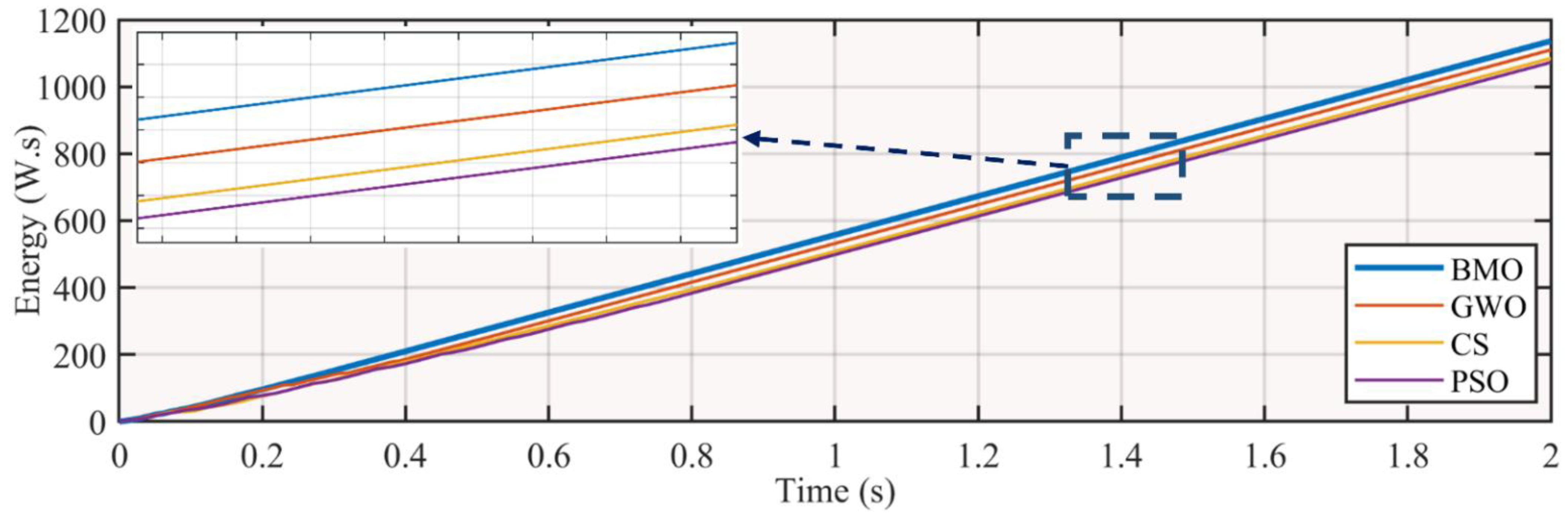
| BMO | 0.3810 | 579.4 | 579 | 99.93 | 1137 |
| GWO | 0.5300 | 579.4 | 578 | 99.75 | 1110 |
| CS | 0.8501 | 579.4 | 576.6 | 99.51 | 1085 |
| PSO | 0.8231 | 579.4 | 574.2 | 99.10 | 1073 |
| Tech | Avg. Tracking Time (s) | Avg. Power (W) | Avg. Tracked Power (W) | Avg. Efficiency (%) | Energy (W.s) |
|---|---|---|---|---|---|
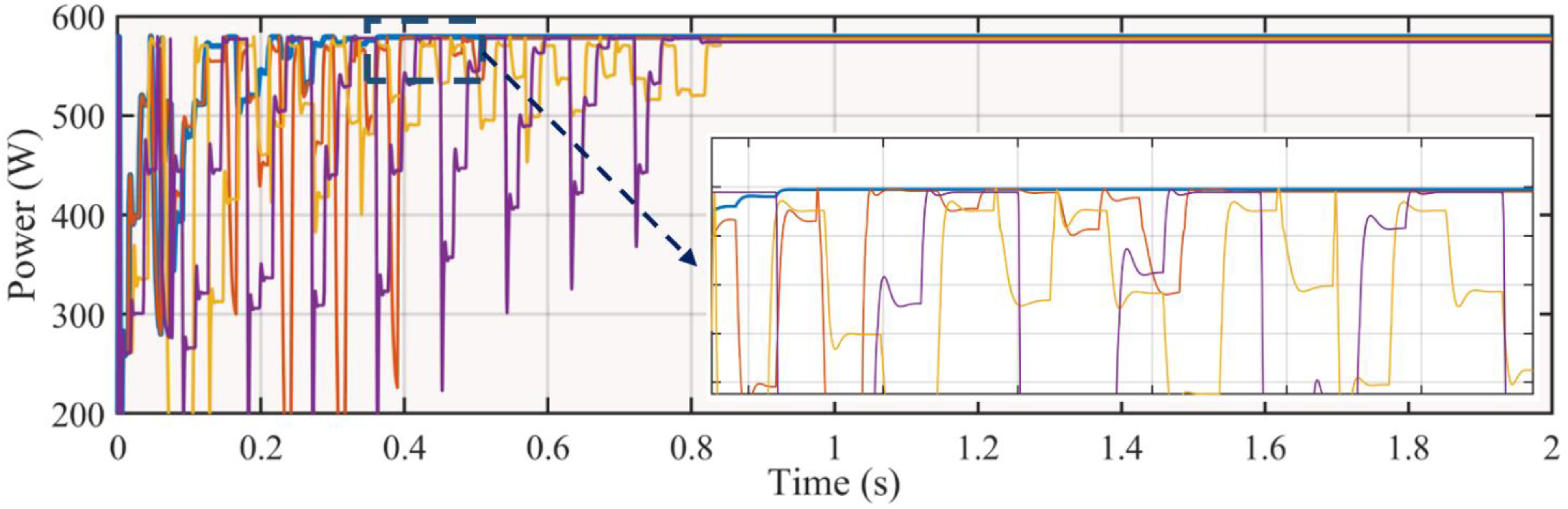
| BMO | 0.2914 | 413.5 | 413.150 | 99.91 | 3269 |
| GWO | 0.3805 | 413.5 | 412.937 | 99.86 | 3259 |
| CS | 0.7200 | 413.5 | 412.425 | 99.74 | 3202 |
| PSO | 0.7511 | 413.5 | 412 | 99.63 | 3216 |
| Tech | Tuning Para. | No. of Random Numbers | Termination Criteria Achieved | Average Tracking Time (s) | Average Efficiency (%) | Modification in Hardware | Speed | MPPT Rating |
|---|---|---|---|---|---|---|---|---|
| BMO | 1 (1) | 4 (4) | No (1) | 0.3362 (1) | 99.92 (1) | No (1) | Fast | 1.571 |
| GWO | 1 (1) | 2 (3) | Yes (2) | 0.4552 (1) | 99.80 (1) | No (1) | Slow | 1.714 |
| CS | 1 (1) | 2 (3) | Yes (2) | 0.7850 (2) | 99.62 (1) | No (1) | Slow | 1.857 |
| PSO | 3 (3) | 2 (3) | No (1) | 0.7871 (2) | 99.36 (2) | No (1) | Very slow | 2.285 |
Publisher’s Note: MDPI stays neutral with regard to jurisdictional claims in published maps and institutional affiliations. |
© 2021 by the authors. Licensee MDPI, Basel, Switzerland. This article is an open access article distributed under the terms and conditions of the Creative Commons Attribution (CC BY) license (https://creativecommons.org/licenses/by/4.0/).
Share and Cite
Tariq, M.I.; Mansoor, M.; Feroz Mirza, A.; Khan, N.M.; Zafar, M.H.; Z. Kouzani, A.; Mahmud, M.A.P. Optimal Control of Centralized Thermoelectric Generation System under Nonuniform Temperature Distribution Using Barnacles Mating Optimization Algorithm. Electronics 2021, 10, 2839. https://doi.org/10.3390/electronics10222839
Tariq MI, Mansoor M, Feroz Mirza A, Khan NM, Zafar MH, Z. Kouzani A, Mahmud MAP. Optimal Control of Centralized Thermoelectric Generation System under Nonuniform Temperature Distribution Using Barnacles Mating Optimization Algorithm. Electronics. 2021; 10(22):2839. https://doi.org/10.3390/electronics10222839
Chicago/Turabian StyleTariq, Mirza Imran, Majad Mansoor, Adeel Feroz Mirza, Nouman Mujeeb Khan, Muhammad Hamza Zafar, Abbas Z. Kouzani, and M. A. Parvez Mahmud. 2021. "Optimal Control of Centralized Thermoelectric Generation System under Nonuniform Temperature Distribution Using Barnacles Mating Optimization Algorithm" Electronics 10, no. 22: 2839. https://doi.org/10.3390/electronics10222839
APA StyleTariq, M. I., Mansoor, M., Feroz Mirza, A., Khan, N. M., Zafar, M. H., Z. Kouzani, A., & Mahmud, M. A. P. (2021). Optimal Control of Centralized Thermoelectric Generation System under Nonuniform Temperature Distribution Using Barnacles Mating Optimization Algorithm. Electronics, 10(22), 2839. https://doi.org/10.3390/electronics10222839