1. Introduction
Unmanned aerial vehicles (UAVs) have been investigated in a wide range of applications, such as security monitoring, smart agriculture, aerial photography and cargo delivery [
1]. UAV-assisted wireless communication has attracted a great deal of attention due to its mobility, flexibility and low cost and the high probability of establishing line of sight (LoS) air-to-ground communication links [
2]. UAVs, which have been involved in mainly three applications of wireless communication—aerial relays, data collection and seamless coverage—can significantly assist the existing terrestrial communications to obtain better performance [
3]. In particular, one of the leading challenges in the Internet of Things (IoT) is to achieve efficient data collection from massive IoT devices. The employment of UAVs can effectively enhance the coverage of IoT devices and significantly reduce the overhead [
4].
Aiming to improve the efficiency of UAV-assisted data collection, several works have been proposed to optimize the UAV trajectory and the communication systems. By properly adjusting the placement or trajectory design of the UAV, the communication distances between the UAV and ground devices can be greatly decreased, and hence better channel gain can be obtained [
5]. In [
6], the data collection time allocation, energy transfer and UAV trajectory planning were jointly optimized to minimize the average age of information for the data collection, where the UAV was utilized to transfer energy and collect data from the ground devices. In [
7], the UAV was employed as an aerial relay to minimize the average peak age of information by jointly optimizing the UAV trajectory, energy allocation and service time allocation. In [
8], a multiantenna UAV was utilized to collect data from a cluster of IoT devices, in which both large-scale fading and small-scale fading were considered. The transmitting power and duration were jointly optimized to maximize the data collection efficiency. Besides, the distances between the UAV and the ground devices could be adjusted by employing user clustering, which was mainly dependent on the coverage of the UAV and improved the performance of the wireless communication system. In [
9], the authors established a mathematical model of LoS probability and pointed out that the LoS probability was dependent on the covering radius, the UAV flying height and the type of environment parameter including suburban, urban, dense urban and high-rise urban. In [
10], the UAV placement problem was formulated as a circle deployment problem to maximize the number of covered users with minimum transmitting power. In [
11], a successive deployment method and a
K-means clustering-based deployment method were proposed to place multiple UAVs in order to cover a maximal number of users in a target area.
The previous works mainly focused on the deployment and trajectory optimization of a UAV which was widely equipped with a single antenna and mainly worked in the microwave frequencies. Recently, millimeter-wave (mmWave) multiple-input multiple-output (MIMO) communication has been introduced into the UAV, since the small wavelength of mmWave enables antenna arrays to be packed in a small space [
12,
13]. However, mmWave systems have to face the challenge of propagation associated with mmWave frequencies, since the transmission at high frequencies will result in severe attenuation [
14]. UAV-aided mmWave communication systems can combat the path-loss of mmWave systems through the beamforming of antenna arrays and also the mobility of UAV [
15], and these systems have many other advantages, such as sufficient spectrum resources, seamless coverage and improved energy efficiency [
16]. A 3D beamforming scheme for a UAV mmWave communication system was proposed to achieve efficient and flexible coverage in [
17], where the phased uniform planar array was adopted. Besides, the joint optimization of UAV deployment and constant modulus analog beamforming of a mmWave base station (BS) was studied to maximize the sum rate of all users [
18].
However, large numbers of radio frequency (RF) chains were employed in the previous UAV mmWave communication systems, which resulted in a high energy consumption and would further reduce the efficiency of the systems, especially when the transmitting power is limited at the UAV. In order to decrease the required RF chains, an effective solution is the beamspace MIMO. By utilizing the lens antenna array, the traditional channel can be transformed to the beamspace channel, and in this way, each beam only contains the signal from a specific direction [
19]. Beamspace MIMO can reduce the number of RF chains, since the beamspace channel in UAV mmWave communication systems is sparse. Signal power is mainly focused on a small part of beams that are selected for transmission, and then the RF chains are attached to the selected beams [
20]. Consequently, beamspace MIMO was introduced into UAV mmWave communication systems to reduce the number of RF chains without significant performance loss [
21].
Furthermore, the IoT network is a fast-growing technology due to its wide range of applications [
22]. In [
23], a trust model based on a non-zero-sum game approach for clustered WSN (CWSN) security was proposed to maximize the data trustworthiness of transmission. In [
24], game theory was adopted in the security issues of an IoT network. A game-theoretic protection approach was proposed to detect malicious sensor nodes. In [
25], a modified Stackelberg game approach was proposed to reduce the required number of IoT nodes involved in achieving the trustworthiness of data. In particular, IoT devices suffer from weaknesses such as the security and data trustworthiness aspects, low processing capabilities and limited power [
26]. Considering the limited energy of IoT devices, the transmission strategy should also be properly designed to achieve high data collection efficiency for IoT applications [
8].
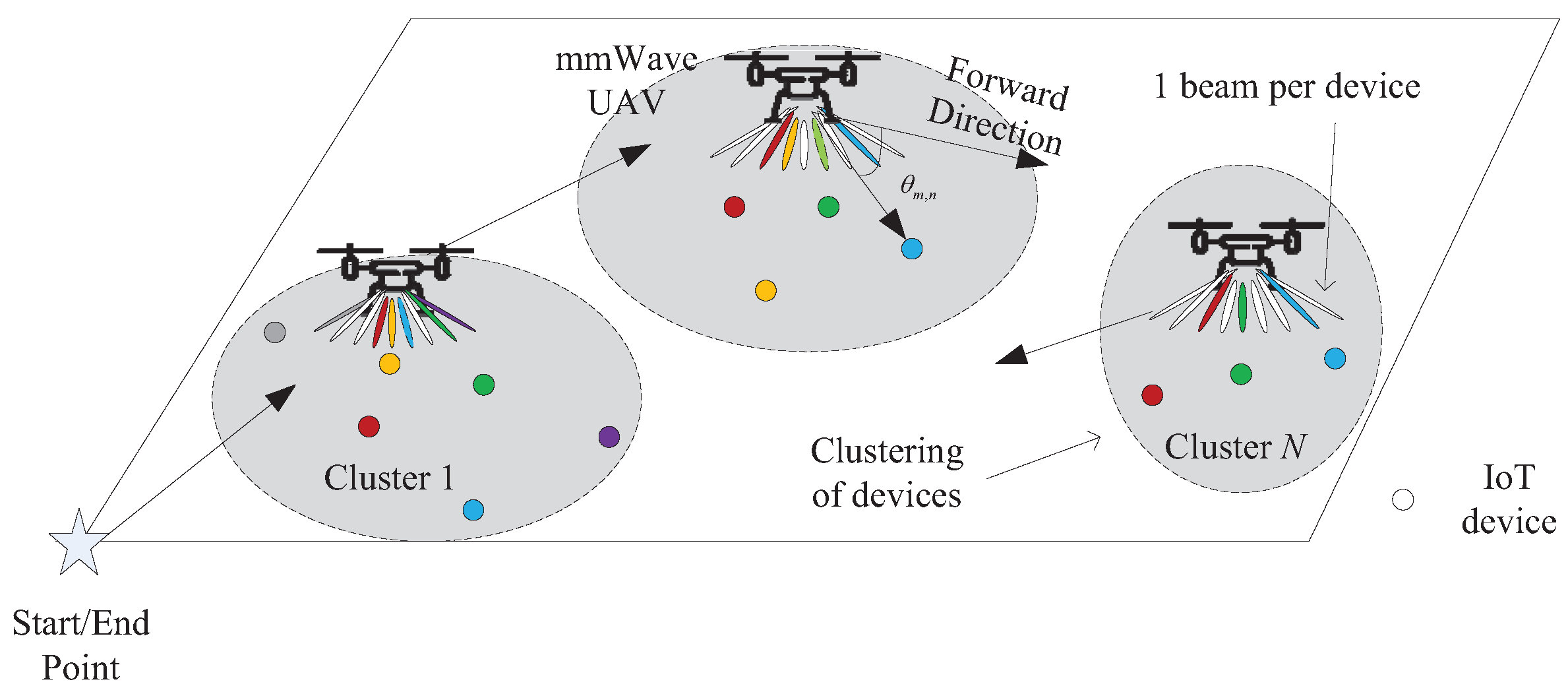
Motivated by the existing research, a UAV-aided mmWave communication system for data collection in the IoT is considered in this paper, where the UAV-aided BS (UAV-BS) is equipped with multiple antennas and operates in mmWave frequencies. The UAV-BS hovers at a fixed height to collect data from several clusters of ground IoT devices in a time-division scheme. In the proposed UAV-BS, the lens array is adopted by the UAV-BS to perform the receiver beamforming. As a result, the sparse beamspace MIMO channel is formed, and the parts of the beams containing the most signal power for ground devices are near LoS paths. Meanwhile, the UAV trajectory is optimized to obtain better channels. Consequently, we formulate a joint optimization problem of UAV trajectory planning, user clustering, beam selection, power allocation and transmission duration to maximize the data collection efficiency, subject to the practical energy constraints of IoT devices. As the problem is nonconvex and the variables are coupling with each other, it is challenging to directly address the problem.
To tackle the proposed complex problem, we decompose it into three subproblems. The first is to attain the optimal beams given the optimal UAV trajectory. The last problem is the joint allocation of power and transmission duration to maximize the data collection efficiency. For the first subproblem, an incremental K-means clustering algorithm and the ant colony optimization (ACO) algorithm are utilized to solve the problem. For the second subproblem, an incremental beam selection algorithm is proposed by incrementally maximizing the sum rate of the mmWave UAV system. The beams that make the highest contribution to the sum rate are selected by the UAV-BS. For the third subproblem, an iterative algorithm is proposed, and the power allocation and transmission duration allocation is optimized in an iterative way. The main contributions of this paper are summarized as follows:
With the UAV trajectory obtained by the incremental K-means clustering and ACO algorithm, an incremental beam selection algorithm for the UAV-BS is proposed to maximize the sum rate of the IoT devices. Zero forcing (ZF) beamforming is utilized to eliminate the interference between IoT devices.
Based on the obtained UAV trajectory, user clusters and the selected beams, the allocations of the transmitting power and transmission duration of the UAV-BS are optimized by alternately optimizing the power allocation and transmission duration, aiming to maximize the data collection efficiency of the UAV-aided mmWave communication systems.
The sum-rate performance of the proposed incremental beam selection scheme and the iterative algorithm are investigated. Simulation results demonstrate the effectiveness of the proposed incremental beam selection scheme and the iterative algorithm.
The symbol notation is summarized in
Table 1.
The rest of the paper is organized as follows. In
Section 2, we present the system model to formulate the optimization problem. In
Section 3, the data collection efficiency of the mmWave UAV communication is optimized.
Section 4 shows the simulation results and discussion. Finally,
Section 5 provides a summary of the main contributions of the study.
3. Solution of the Problem
It is difficult to directly solve the problem in (22) because of the coupling variables and the nonconvex objective function and constraint (22e). Motivated by the “divide and conquer” concept, the original problem is tackled in three steps. First, since the UAV trajectory is entangled with the clustering strategy, by introducing the K means clustering algorithm and ACO algorithm, the UAV trajectory and the user clustering can be determined. Secondly, giving the trajectory of the UAV and the user clustering, a beam selection scheme is proposed to determine the selected beam set. After finding the optimal trajectory of the UAV, user clustering and the selected beam set, the coupled transmitting power and transmission duration can be solved in an iterative way.
3.1. Solution of the UAV Trajectory and User Clustering
Our proposed solution is to use a K-means clustering algorithm to partition the K devices into N subsets that represent N coverage areas of the UAV-BS. If the UAV-BS is assigned to service a subset, it will position itself in the subset centroid and serve up to devices inside of that subset. This is because the maximal beams can be utilized to serve devices. In order to avoid multiuser interference, each beam can be selected by a single device, namely . Then, the UAV successively visits N hovering locations, and the trajectory planning of the UAV can be solved by the ACO algorithm.
In this paper, we assume the wireless links between the UAV and the devices are dominated by LoS. According to [
9], it has been demonstrated that the UAV altitude
and the coverage radius
determine the LoS probability. Meanwhile, the LoS probability is also dependent on the environment condition. In particular, in suburban areas, given a fixed UAV altitude
, when the maximal coverage radius of the UAV
, the wireless channels in the coverage area are dominated by the LoS.
We assume that the locations of
K devices before clustering are defined as
. In the
K-means clustering algorithm, the partition criterion is based on a sum-of-squared-error criterion [
11], which can be expressed as
where
is a binary variable, denoting whether the
kth device belongs to the
nth cluster.
means that the
kth device belongs to the
nth cluster, and we define
. When
, the
kth device will not be assigned to the cluster
n.
is the center location of the
nth cluster, denoting the UAV location in cluster
n. In particular, the center location of a certain cluster is calculated by all devices in that cluster, which is given by
where
. Hence, we utilize the
K-means clustering algorithm to partition the devices and determine the UAV locations. Since the
K-means clustering algorithm assumes that the number of clusters is known, we determine the cluster number in an incremental way. We first start with a minimum cluster number
. Then, we increase the number of
N until both constraints of the maximum UAV coverage area and the maximal number of devices that the UAV can serve at the same time are satisfied. The proposed solution of the UAV trajectory and user clustering with an incremental
K-means clustering algorithm is summarized in Algorithm 1.
| Algorithm 1 The proposed solution of the UAV trajectory and user clustering with an incremental K-means clustering algorithm. |
| Require: ,for , , |
| Ensure: N, , ,for and |
| 1: Initialization: initial clustering number . |
| 2: Repeat |
| 3: Randomly select points in the target area as the center points . |
| 4: Repeat |
| 5: Calculate the Euclidean distance between each device and any center of cluster. |
| 6: if |
| 7: , the kth device is allocated in the cluster n |
| 8: end if |
| 9: Recalculate the center of the clusters based on (24) |
| 10: Until none of the is updated. |
| 11: Calculate the maximal distance between the devices and the its cluster center, and count the amount of devices in each cluster . |
| 12: if and |
| 13: |
| 14: break |
| 15: else |
| 16: |
| 17: end if |
In order to collect data from each cluster, these
N clusters are scheduled under multiple access time division. UAV trajectory planning is performed to utilize the minimum energy required for visiting
N clusters. Since a UAV’s flying energy consumption is dependent on the flying distance, the UAV trajectory planning can be transformed into finding the shortest route to visit
N clusters in turn. Therefore, the UAV trajectory problem is a classic traveling salesperson problem, which can be solved by the ACO algorithm [
33].
3.2. Incremental Beam Selection Scheme
Owing to the sparse structure of the beamspace channel, the beamspace channel for the
mth device in the cluster
n has dominant beams, and the number of RF chains can be reduced [
34]. Given the UAV position of the
nth cluster
and the transmitting power of the
mth device in cluster
n, the beamspace channel
and the sum rate are known. The proposed beam selection scheme selects the beams whose contribution is the best in terms of the sum rate. With the aim of minimizing the number of RF chains
of cluster
n, we assume that each device is served by only one beam, and thereby
. The number of candidate beams is
, and the indices of the beams which are selected by the devices in the
nth cluster are stored in beam set
.
Based o (
18)–(
21), we can select the required beams for the devices in the
nth cluster one by one based on the incremental beam selection algorithm, which identifies the beams with the maximal gains in terms of sum rate. This incremental beam selection algorithm is summarized in Algorithm 2.
| Algorithm 2 Proposed incremental beam selection scheme. |
| Require: |
| Ensure |
| 1: |
| 2: |
| 3: for |
| 4: |
| 5: for |
| 6: |
| 7: |
| 8: |
| 9: for |
| 10: |
| 11: end |
| 12: |
| 13: end |
| 14: |
| 15: |
| 16: |
| 17: end |
| 18: |
3.3. Iterative Solution
Given the UAV positions and the beam selection scheme, the main problem of tackling the optimization problem (22) is the coupling relationship between the transmission duration and the transmitting power . To solve this problem effectively, we recast it into two subproblems. One is power allocation for a given transmission duration, and the other is allocating the transmission duration given the transmitting power . The two subproblems are solved alternately. Finally, the proposed iterative optimization algorithm is summarized.
3.3.1. Power Allocation
For a given transmission duration
, the power allocation problem can be expressed as
where
represents the number of iterations. The optimization problem (
25) is greatly simplified. According to (
20)–(
21), the achievable rate of the
mth device in cluster
n is given by
It is easy to observe that
Consequently,
is concave with respect to
. The constraint is also convex with respect to
. Therefore, the problem (
25) is a convex optimization problem which can be solved by CVX effectively.
3.3.2. Transmission Duration Allocation
With the power allocation
obtained by solving (
25), the transmission duration optimization can be formulated as
It is easy to see that the objective function and constraints are both convex. Thus, the problem (
28) is a convex optimization problem. In order to efficiently solve the optimization problem (
28), the communication duration
T should be considered in three cases. The first one is
; the second one is
; the third one is
. If
T is not large enough to complete the communication mission of all clusters, the cluster with the highest sum rate will be served as a priority. As a result, the clusters are reordered according to
For the first case,
, which also can be written as
Thereby, the optimal solution of optimization problem (
28) is given by
For the second case,
can be rewritten as
The optimal solution of (
28) can be written as
For the third case,
can be rewritten as
The optimized solution of optimization problem (
28) is shown as
Based on the above discussion, an iterative algorithm is proposed to alternately solve the optimization problems (
25) and (
28), as summarized in Algorithm 3.
| Algorithm 3 Iterative algorithm |
| 1: Initialization: , for , . |
| 2: Repeat |
| 3: , solve problem (25) to obtain the optimal solution . |
| 4: For , solve problem (28) with the consideration of three cases to obtain the optimal solution denoted as . |
| 5: Update:. |
| 6: Until The increase of the is less than a threshold , or the maximal number of iterations is reached. |
It is clear that the achievable data collection efficiency increases with the increased number of iterations, which can be shown as
Thus, Algorithm 3 exhibits convergence.
4. Performance Analysis
In this section, we evaluate the performance of the proposed algorithm. We consider that a UAV visits
N clusters in turn and collects data in a mmWave system. The terrestrial devices are randomly distributed in the square area of
(m
), and the UAV flies right above the coverage area. The UAV flying trajectory starts from
and ends at the same point. The CPU of our computer was Intel i9, and the RAM was 16 GB. The main default parameters of this simulated UAV mmWave communication system are listed in
Table 2.
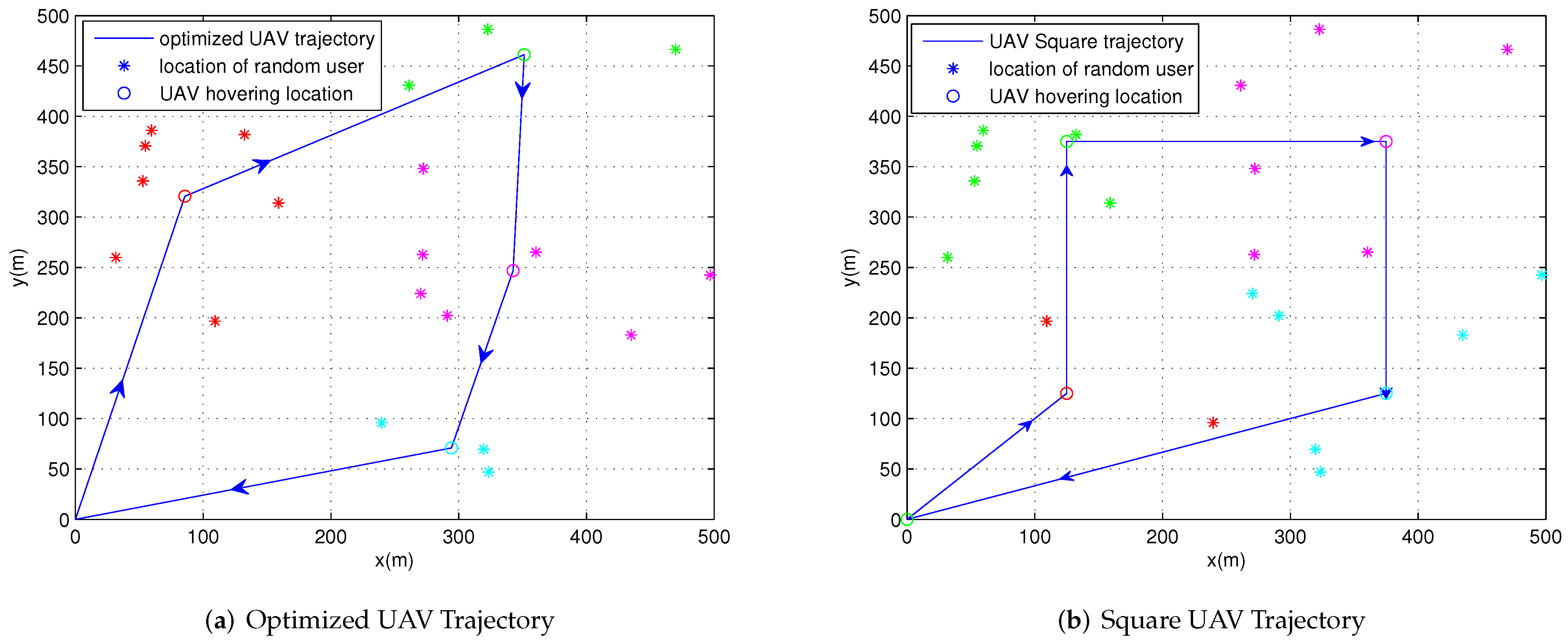
Figure 2 depicts the optimized UAV trajectory and the square UAV trajectory, both with the aid of the proposed incremental beam selection scheme and the iterative algorithm. The number of devices is
. All the devices are divided into
clusters. Each cluster has an unequal number of devices. The total communication duration
T is set as
s, and the budget transmission duration
is
s. The total energy constraint of each device
is equal to 4 J. The UAV flies at a fixed height of
m.
Figure 2a shows the optimized UAV trajectory and the corresponding clustered devices, while
Figure 2b shows the square UAV trajectory and the devices in each cluster. Specifically, the data collection efficiency of the optimized UAV trajectory is about 1764 bits/Hz higher than that achieved by the square UAV trajectory.
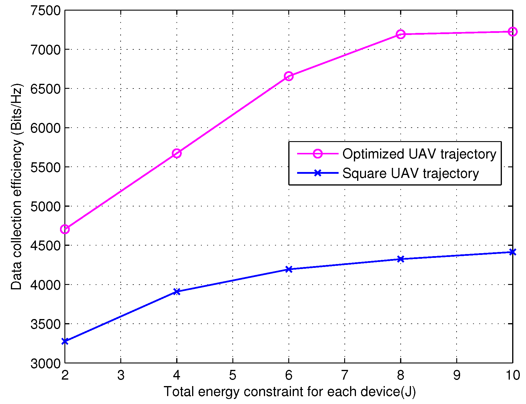
Figure 3 depicts the data collection efficiency as the function of the total energy constraint of each device for the proposed optimized UAV trajectory, in comparison with the performance attained by the square UAV trajectory. The both trajectories are aided by the incremental beam selection and iterative algorithm. The system has
,
,
s,
s, and
m. As expected, the optimized UAV trajectory outperforms the square UAV trajectory. In particular, for the system with
, the data collection efficiency attained by the proposed optimized approach is about 2868 bits/Hz higher than that of the square UAV trajectory.
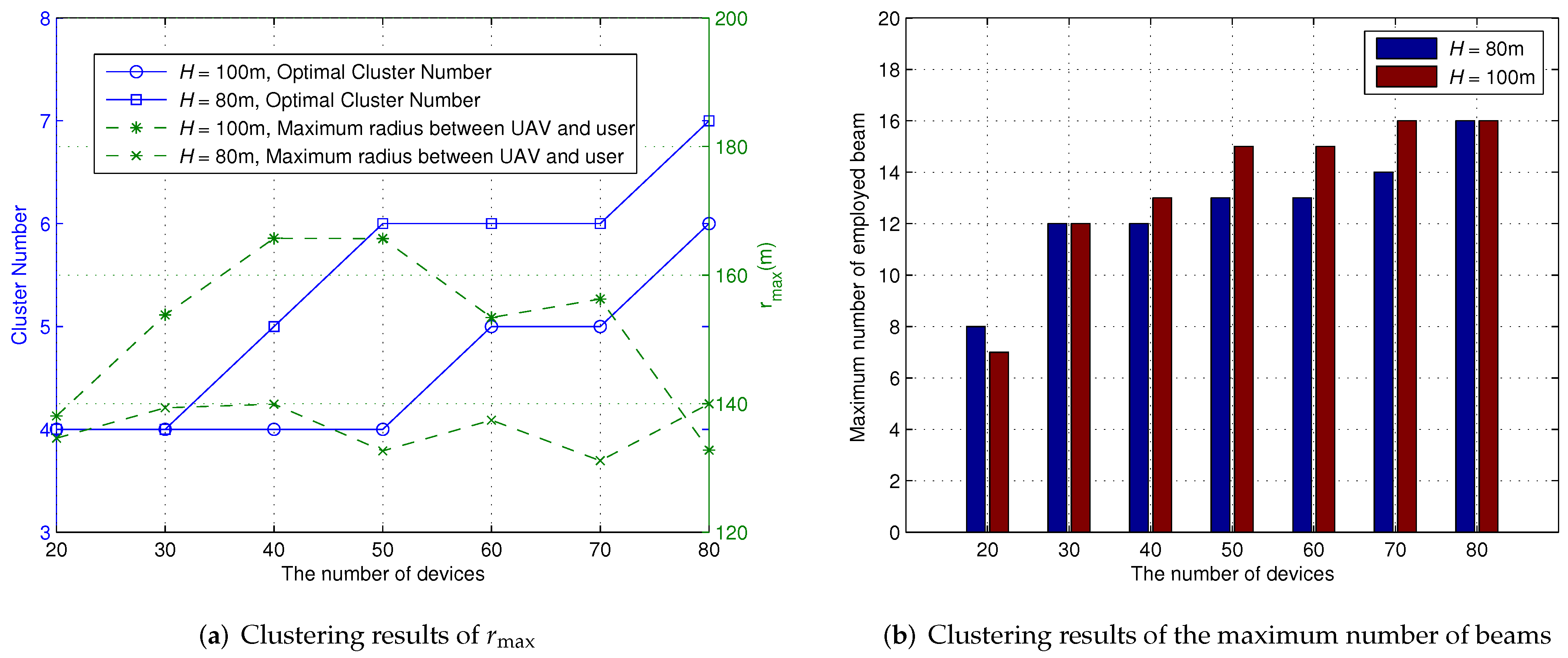
In
Figure 4, we investigate the cluster results versus the number of devices of the proposed scheme.
Figure 2a shows the cluster number and the maximum distance
between the UAV and the device versus the number of devices of the proposed scheme.
Figure 2b shows the maximum number of employed beams versus the number of devices of the proposed scheme. The number of devices in each cluster is unequal. When the UAV flies at a fixed height
m, and the maximum coverage radius of the UAV is
m. When the height of UAV is 80 m, the maximum coverage radius of the UAV is
m. The maximum number of devices in each cluster is 16. Each device is served by a single beam. It can observed from
Figure 4 that the number of clusters increases with the increasing number of devices, due to the limited coverage area
and the constraint of the maximum number of devices in each cluster. From
Figure 4, the tight constraint of
has an influence on the number of clusters. When
, the cluster number of
m is 6, and
m. Meanwhile, the maximum number of employed beams is 16. However, for
and
m, the cluster number is 7, and
m. Meanwhile, the maximum number of employed beams is 16.
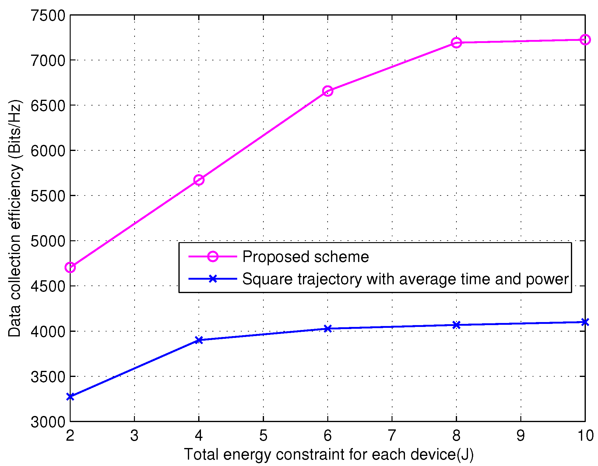
In
Figure 5, we compare the data collection efficiency as a function of the total energy constraint of each for device for the proposed scheme and the square trajectory with average time and power. The system setup is
,
,
s,
s,
, and
m. For the square trajectory with average time and power,
,
, and
,
[
29]. The MCMS scheme is utilized for the square trajectory with average time and power scheme. From
Figure 5, the proposed scheme shows better performance than the square trajectory scheme with average time and power.
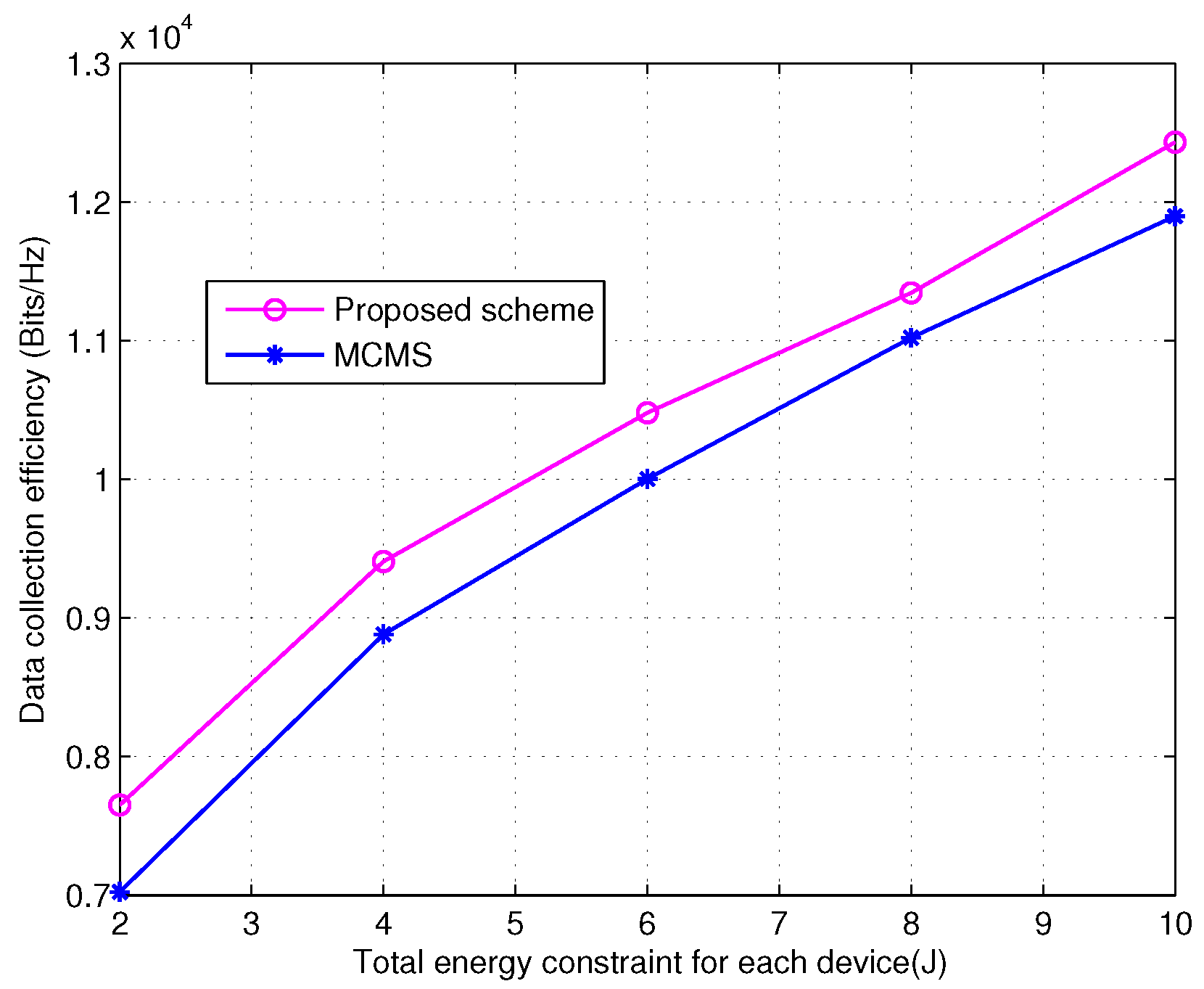
Figure 6 compares the data collection efficiency as a function of the total energy constraint of each device for the proposed incremental beam selection scheme and the maximum channel magnitude scheme (MCMS) [
34], both adopting the proposed UAV trajectory and user clustering scheme and the iterative algorithm. Since the proposed scheme selects one beam for each device, the MCMS with one beam per device is selected as a reference. There are
devices randomly distributed in the specific area. All the devices are separated into
clusters, and the number of devices in each cluster is different. The total communication duration
T is 400 s, and the budget transmission duration
is set as
s. The UAV flies at a fixed height of
m. As shown in
Figure 6, the data collection efficiency of the incremental beam selection scheme significantly outperforms that of the MCMS. This is because the MCMS select the strongest beam for each device, and thereby some devices may share the same beam, which causes interference from the same beams for different devices.
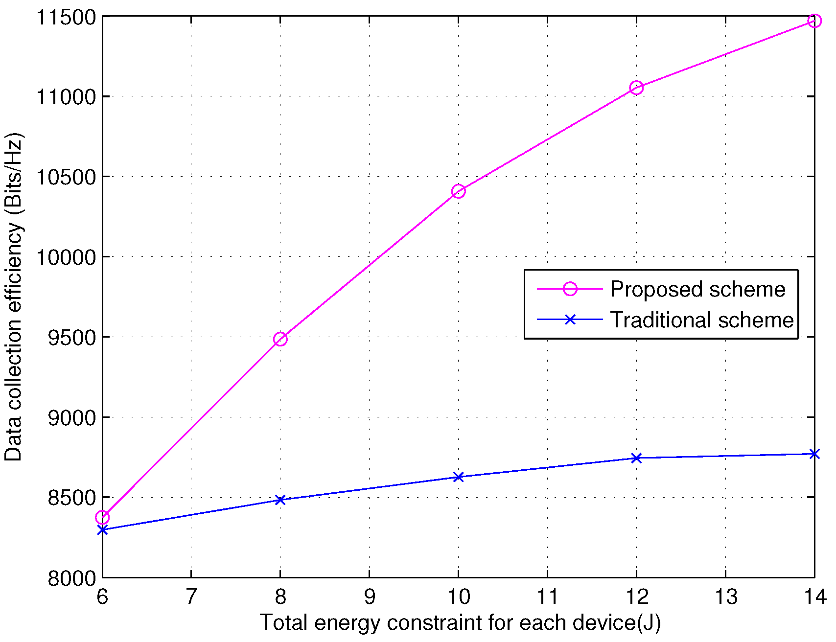
In
Figure 7, we compare the data collection efficiency as a function of the total energy constraint of each device for the proposed iterative algorithm and traditional scheme, both with the aid of the proposed UAV trajectory and user clustering scheme and the incremental beam selection scheme. The system setup is
,
,
s,
s,
and
m. In the traditional scheme,
,
, and
,
, which is widely used in the literature [
8]. From
Figure 7, the proposed iterative scheme shows better performance than the traditional scheme. For
J,
, the data collection efficiency of our proposed iterative scheme is about 1000 bits/Hz higher than that of the traditional scheme.
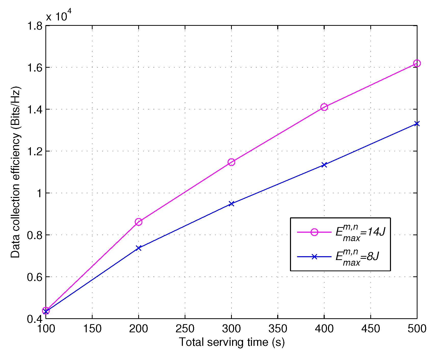
Figure 8 investigates the data collection efficiency versus the total serving time for the proposed scheme with a different total energy constraint for each device. The system setup is
,
,
s and
m. The total energy constraint for each device
is 8 J or 14 J,
. It can be observed from
Figure 8 that, given the total energy constraint for each device, the data collection efficiency increases with the increased serving time
T. When
s, the data collection efficiency of
J is about 1780 bits/Hz higher than that of
J.
5. Conclusions
In this paper, a UAV-aided mmWave communication system for the IoT is considered, and the maximization problem of the data collection efficiency is investigated, where the UAV trajectory planning, user clustering, beam selection, power allocation and transmission duration allocation are jointly optimized. To tackle this complex and nonconvex problem, we have decomposed it into three subproblems. Firstly, the incremental K-means clustering algorithm and ACO algorithm are proposed to solve the joint subproblem of UAV trajectory planning and user clustering, in which the cluster number, clustering method and hovering location of UAV are optimized according to the incremental K-means cluster algorithm. The UAV trajectory planning is transformed into a traveling distance minimization problem, which is solved by the ACO algorithm. Then, an incremental beam selection scheme is proposed to implement beam selection with one beam per device. With the aid of optimal UAV trajectory planning and the incremental beam selection scheme, an iterative algorithm is proposed to maximize the data collection efficiency by alternately solving the power allocation and transmission duration allocation problems. The data collection efficiency is finally evaluated for the proposed algorithm, and the results demonstrate that the proposed solutions can achieve excellent performance.
Our future work may focus on the unitary planar array (UPA). The UAV-BS utilizing UPA could place more antennas in small area. The UPA includes the elevation angle and azimuth angle, and thereby the beamforming of UAV-BS can be carefully designed to achieve better performance.


