Review

Review on Control Techniques for EV Bidirectional Wireless Chargers

by
Alicia Triviño
*,
Jose M. Gonzalez-Gonzalez
and
Miguel Castilla
Department of Electrical Engineering, Escuela de Ingenierías Industriales, University of Málaga, 29071 Málaga, Spain
*
Author to whom correspondence should be addressed.
Electronics 2021, 10(16), 1905; https://doi.org/10.3390/electronics10161905
Submission received: 26 June 2021 / Revised: 27 July 2021 / Accepted: 29 July 2021 / Published: 9 August 2021
(This article belongs to the Special Issue Grid Integration of Electric Vehicles Using Wireless Power Transfer)

Abstract

:
Due to their flexibility, Electric Vehicles (EVs) constitute an important asset for the integration of renewable energy sources in the Smart Grid. In particular, they should have a dual role: as a controllable load and as a mobile generator with a low inertia. To perform these tasks, chargers must provide the electronics with a power flow from the grid to the vehicle and vice versa. This bidirectionality can also be implemented in wireless chargers. The power converters, the compensation networks and the coil misalignment must be considered when designing the control of these systems. This paper presents a review about the proposed algorithms to control the active and the reactive power flow in a bidirectional wireless charger.

1. Introduction

The transport sector accounts for nearly 30% of the CO2 emissions in Europe and USA [1], so it it is convenient to promote the use of Electric Vehicles (EVs) to achieve the target of reducing this figure. The benefits of using EVs is not only foreseen in terms of sustainability, but it can be an important resource in distribution networks. If we take into account that the probability of an EV to be parked anywhere in the midday period is over 0.9 and the probability of the EV to be parked at home is higher than 0.5, it is evident that the potential of using EVs as batteries supporting the grid is promising [2]. These assets do not need purchasing and maintaining costs that the distribution system operators need to invest in Battery Energy Storage Systems (BESS). Thus, EVs will also play an important dual role in smart grids. First, it can be managed as a controllable charge so that the vehicle may be charged when needed. Secondly, EVs can be seen as mobile self-contained generators with a practically null inertia and a significant flexibility. When required, EVs could also provide energy to the electrical network with a short response time. This double role eases the integration of renewable energy sources into electrical grids [3]. When an excess of renewable power generation is detected in the grid, it could be directed to charge the vehicle batteries. In an analogous way, the battery could offer ancillary services for voltage or frequency regulation if conveniently managed in an entire fleet [4]. The suitability of acting as a load, as a generator or in an idle state depends on several factors related to the system to which it is connected and the battery status. Taking into account these parameters, advanced algorithms may be proposed to decide which function should execute the charger [5].
Thus, the battery of an EV could have a double functionality: being a controllable load or acting as a generator. In addition, the vehicle could be connected to different systems: V2G (Vehicle-to-Grid) when connected to a power system, V2B (Vehicle-to-Building) when connected to a stand-alone building and V2H (Vehicle-to-Home) when connected to a home. According to the research agency Navigates, the V2G capacity was at 2.6 GW in 2017 [6]. This estimate represents only 1% of the global grid services market (e.g., frequency regulation). However, this figure is growing and will reach a power capacity of 20.5 GW (4% of the grid services) in 2026. Voltage regulation can also be a grid service provided by a fleet of EVs. For this operation, EVs are expected to generate reactive power.
In all these scenarios, the power transfer is bidirectional, so the power converters must be designed for this. Control algorithms play a relevant role to configure the operation mode of the power converters. Depending on their configuration, the role of the EV as a load or as a generator can be adjusted. In particular, with the power converters, it is possible to configure the active power and/or the reactive power consumed or generated by the EV.
Some initial approaches focused on the active power (P) configuring the power level and the power flow. However, complete and advance control techniques require the adjustment of both active and reactive power so that the EV can provide services for frequency and voltage regulation. When considering both types of power, we can talk about the operation of the control in a four-quadrant scheme, as illustrated in Figure 1. This Figure corresponds to the power consumed by the battery. The charger operations in Quadrant-I and Quadrant-IV are associated to EV battery discharging. Alternatively, operations in Quadrant-II and Quadrant-III correspond to EV battery charging. The particular quadrant is related to the reactive power flow. If the charger operates in Quadrant I or Quadrant II, reactive power is positive, and thus, it behaves as an inductive load. In Quadrant III and IV, the charger delivers reactive power so that it is working as a capacitive load. Some researchers referred to the control of P and Q as the Vehicle-for-Grid (V4G) operations [7]. Advanced algorithms will work in the quadrant areas for different values of P and Q. However, initial approaches that do not consider the adjustment of a reactive power to a reference power different from null just move on the axes of Figure 1. Thus, there are eight operation modes as identified by [7]:
  • Mode I, in which the battery is charged with a null power factor. It is a G2V operation.
  • Mode II. The battery is discharged with a null power factor in a V2G power transfer.
  • Mode III. The controller forces the combination of power converter and battery to consume positive reactive power and null active power. Under this configuration, the system has a pure inductive load on the secondary side.
  • Mode IV. With a null active power and a negative reactive power, the load on the secondary side (power converter and battery) represents a pure capacitive load.
  • Mode V. The controller can set any point in the area of the first quadrant so there is a positive active and a positive reactive power. The power converter and the battery on the secondary side works as a generic inductive load.
  • Mode VI. The active power flows from the battery to the grid, so it is a V2G operation. In addition, the set composed of the secondary power converter and the battery consumes positive reactive power. Thus, it is also an inductive V4G process.
  • Mode VII. As in Mode VI, the active power flows from the battery to the grid, but the load on the secondary side generates reactive power, that is, it works as a generic capacitor.
  • Mode VIII. In this mode, the power converter and the battery on the secondary side consumes active power flow and generates reactive power.
Wireless Power Transfer (WPT) offers the possibility of implementing an autonomous EV charge/discharge without relying on the physical connection between the vehicle and the charge station. This capability is especially convenient for self-managed V2X operations in order to trigger the charge/discharge process in periods when the user is unable to actively participate. WPT includes several technologies, but the most mature one is the based on the induction principle [8]. The basis of this kind of charger is a magnetic field flowing between two air-core coupled coils in the range of 80–90 kHz. Due to this operational frequency, power converters in wireless chargers have a different composition, topology and control when compared with wired chargers. The work in [9] presents a review about power converters in bidirectional wired and wireless chargers. This review is limited to the power converters topology. Our approach extends this work by focusing on the control used to operate the converters in wireless chargers. Specifically, we study how the control techniques applied in the related literature can achieve the following goals:
  • Power flow sense. It is possible to control the flowing of the power, that is, if the power flows from the grid to the EV battery or vice versa.
  • Four-quadrant operation. Basic control algorithms only focus on the active power, but advanced V2G services also require the control of the reactive power. A relevant feature of the control techniques is the power quadrants (eight modes) on which they can operate.
  • It is possible to approximate the active and/or the reactive power in the charging point to reach their corresponding reference power level, even when coil misalignment occurs.
Wireless charging is still in the development stage. Although the market for these chargers is not yet relevant, a Compound Annual Growth Rate (CAGR) of between 30–50% from 2020 to 2025 [10] is expected. Some car manufacturers, such as Audi, BMW, the Hyundai group or Mercedes-Benz, have already shown their interest in this technology, and some of them have even launched a model on the market. There are also some independent wireless charger manufacturers that are betting harder on this technology, such as Momentum Dynamics, Plugless Power and Witricity. This last company is the one that has opted the most for wireless V2G technology and is developing, together with Honda, a commercial charger with bidirectional capabilities.
The remainder of the paper is structured as follows. In Section 2, a review about V2X services is described in order to identify the requirements of V2G wireless chargers. Section 3 addresses the description of a generic model of V2G wireless chargers. Based on this model, Section 4 explains the main control techniques applied to their kind of charger. The explanation focuses on the identification of the above-mentioned features. Section 5 describes the most relevant works on control algorithms for bidirectional wireless chargers. The challenges still to overcome are identified in Section 6. Finally, Section 7 summarizes the main conclusions of this work.

2. V2X Services

EVs, with recent advances in battery charging technologies, can also be utilized as grid-integrated distributed energy storage systems to manage energy with greater flexibility or to provide grid services in an efficient and cost-effective manner. The use of vehicle batteries for these services causes additional degradation and may compromise their autonomy since the available energy depends on the operations carried out. Therefore, the generation of benefits for the user seems necessary to arouse their interest and make these systems available.
One-way chargers are capable of providing some of these services to a very limited extent. However, bidirectional chargers bring a new dimension, as power not only flows to the battery but also back to the grid. This broadens the range of services that vehicle energy storage can provide.
The Vehicle-to-Everything (V2X) concept is used to group all the possibilities provided by vehicle storage. Despite the advantages that these services can provide to the network and its users, the technology required for this is not yet mature enough and commercial solutions are scarce on the market.

2.1. Grid-to-Vehicle (G2V)

The growth prospects for electric vehicles can be a handicap for electric systems. The global electricity demand due to the implementation of these vehicles is expected to reach between 500 and 1000 TWh [11] in the year 2030, that is, an approximate increase of between six and eleven times compared to the demand in 2019.
The main difficulty in meeting this increase in demand lies in the need to avoid the concentration of vehicle charging at certain times of the day, such as returning from work. The management of the charging of the vehicles seems, therefore, a fundamental issue for the viability of the electric vehicle. The measures aimed at this management are grouped in the G2V services.
One of the main G2V services is demand response. Demand response is a mechanism developed to encourage consumers to consume more at certain times [12]. This incentive is based on a significant saving in the cost of energy, which is possible to achieve by consuming during the off-peak hours or in the periods of maximum renewable generation.
Following the same energy price strategy, it is also possible to define negative demand response. The objective of this mechanism is to discourage energy consumption in peak demand periods. Generally, this objective is achieved by the electricity markets themselves, with hourly prices that are directly related to electricity demand [13].
The simultaneous effect of both strategies translates into a shift of energy consumption from the periods of peak demand to off-peak demand. This redistribution of demand is known as peak-shaving or valley-filling. The effect of these strategies is not only reduced to a reduction in the price of energy but also to lower losses in the electricity system and lower investments in networks to guarantee energy supply.
Figure 2 shows the effect of applying these strategies on a standard consumption profile.
The maximisation of these beneficial effects for electrical systems is found in coordinated charging. This strategy allows an optimal distribution of the charging of the vehicles in the hours of lowest consumption and price. This type of strategy is becoming more and more viable, thanks to the connectivity and controllability of the chargers [14] and the development of smart grids [15]. The positive effects of coordinated charging [16,17] make this technology one of the development focuses of researchers, whose main contributions are in the development of operation algorithms [18,19].

2.2. Vehicle-to-Grid (V2G)

V2G technology enables the vehicle to use the energy stored in its batteries that provide additional services to the grid. These services not only include cost reduction as in G2V services but also improve the quality and reliability of the electrical system.
One of the main V2G services is the demand charge reduction [20]. This mechanism allows the energy stored in the batteries to be used to reduce demand during peak hours. This has a direct effect on the price of energy. However, it is not the only advantage these systems provide. Losses of the electrical system are also affected since part of the energy that must be provided in peak hours approaches the point of consumption in off-peak hours. Peak shaving also allows investment deferral to increase grid capacity [21]. The benefit for the EV user is found in the price difference between the off-peak hours when he buys the energy and the peak hours when he sells it.
The immediate availability of energy provided by storage systems, coupled with the high response speed of the power electronics, also increases the reserve capacity of the system [22]. This improvement reduces the operating costs of the system since the cars are parked most of the day, and the availability of large generation plants is not required. This same availability of energy and proximity to demand points also help to provide an emergency back-up system in the event of contingency situations in the electrical grids or in generation.
The contribution to the reduction of operating costs of the system also extends to its participation in the regulation mechanisms. Locally, EVs can participate in voltage regulation [23]. This is achieved thanks to the power electronics’ ability to inject or absorb an accurate amount of reactive power to regulate the power grid voltage to a preset level, which is determined by the power utility.
However, the service that is estimated to provide the greatest value to both the user and the electrical system is frequency regulation. The function of this mechanism is to keep the grid frequency at its nominal value, balancing generation and demand [24]. There are multiple studies on the feasibility and profitability of participating with electric vehicles in frequency regulation markets. In [25], the authors analyze the profitability of this service in the Danish and Japanese markets considering charger losses, electricity prices, the State-Of-Charge (SOC) of the battery and its degradation. The study concludes that benefit is only achieved when industrial electricity prices are considered, obtaining an average of €3500 for five years. The work presented in [26] provides a more optimistic analysis of participation in these mechanisms, with results reaching EUR 100 per year for each kW of power capacity. However, the authors warn of the high influence of user habits on this final value.
Nowadays, V2G services are scarcely executed, not only due to the technological challenges posed by this technology but also at a social and regulatory level. Regulatory challenges are a particularly strong barrier because, without the necessary modifications, the participation of small users is not attractive, and the manufacturers do not opt for this technology. Some of the regulatory challenges are double taxation of electricity, enabling domestic users to participate in Transmission System Operator (TSO)-level markets or the development of standards to guarantee the compatibility of the systems [27].
There are various projects around the world which have the objective of evaluating this technology. One of the most relevant is The Parker Project [28], developed in Denmark, which used fifty V2G chargers to evaluate various services for TSO and Distribution System Operators (DSO). The e4Future project have also deployed twenty V2G chargers on the UK grid to explore their capabilities [29].

2.3. Vehicle-to-Building (V2B)

The V2B concept operates on a smaller scale than the V2G. Unlike V2G, this concept encompasses a few EVs and consumers that can be grouped together as microgrids. Consumers that are part of these groups do not have to be only domestic since both commercial and industrial consumers fit perfectly into the consumption that the V2B handles.
One of the advantages of V2B compared to other concepts of energy exchanges with vehicles is that the services can be focused on consumers belonging to the microgrid or to the external network. This allows increasing the number of services in order to maximise the profit. To decide the operations of all participants, it is usual to resort to its own control that can be centralized or decentralized [30], and that provides independence with respect to the greater electric grid [31]. This independence can even cause both systems to be disconnected so that the control of the microgrid would only look after the interests of its users.
The improvement of power quality and the minimisation of losses is an example of this. Although the V2G analyzed the voltage regulation of the electrical network, with the V2B, it is also possible to compensate the power factor of the consumers so that the network does not have to provide reactive power or the customer has to install capacitor banks. The authors of [32] analyze the beneficial effects of EVs for voltage regulation in the low voltage network with a practical case on the electrical system of Denmark. Of course, back-up services are also part of V2B to increase power quality.
The V2B also represents a benefit for increasing the penetration of renewable energy since they can provide capacity-firming services [33]. The objective of this service is to smooth the variable power generation. Although these services can also be categorized in V2G, it also helps to increase self-consumption levels at a more local level [34].
Finally, it is also worth highlighting peak-shaving as one of the applications of these systems [35]. Unlike the peak-shaving of the G2V, the energy stored in the batteries can be used to balance the demand profile, reducing system losses and energy costs. Cost reduction is achieved by shifting part of the consumption to the hours of highest renewable generation or acquiring energy from the grid at a lower price to use it in the hours of highest cost.
These analyzed services can even be implemented at a lower level with a concept called Vehicle-to-Home (V2H) [36] in which all the measures are aimed at a single consumer and their electric vehicle. Some publications also define the Vehicle-to-Load (V2L) concept [37], although this is more oriented to specific back-up services or to the supply of loads with limited access to the grid.
In a similar way to V2G technology, the commercial solutions available for V2H are very limited. Some car manufacturers have made various developments in this regard. These include Mitsubishi Motor Corporation with its Dendo Drive House system and Nissan Motor Corporation with its LEAF-to-Home system. The charger manufacturer Wallbox has also opted for this technology with its Quasar system, which is available with a maximum power of 7.4 kW.

2.4. Aggregator

Most of the ancillary services on which V2G can get a greater benefit imposes a minimum power capacity to participate. For instance, a minimum of 100 kW or 1 MW is necessary to bid in the frequency regulation market [38]. Thus, a single EV cannot participate by itself in this type of market as batteries are lower power. Due to this restriction, an aggregator manages a pool of EVs and coordinates their operation to reach a global goal. For this task, the aggregator gathers some information about the market situation (e.g., prices) and some data about the vehicle’s status (e.g., battery SOC, driving preferences, etc.). With these parameters, the aggregator executes an algorithm to decide the V2G operations of the vehicles it manages.
Diverse types of algorithms have been defined in the related literature based on predictive behaviours or statistical modelling of EV behaviour. Their formulation mainly depends on the model of the power system to which the EVs are connected and the operations considered. There are several works that take advantage of the bidirectional power flows of EVs. In [39], the authors propose an aggregator scheme for frequency regulation. Unlike other jobs, the goal of this aggregator is the fair distribution of energy between electric vehicles, rather than simply trying to optimise the aggregator profit. The authors in [40] also present an aggregator algorithm for regulation, but they opt for a solution based on a Welfare-Maximising Regulation Allocation (WMRA) algorithm. One of the main difficulties for frequency regulation is estimating the available power. This topic is addressed in [41]. The work in [5] executes an algorithm to maximise the revenues that a fleet of vehicles get by adjusting where and when the V2G operations are executed.

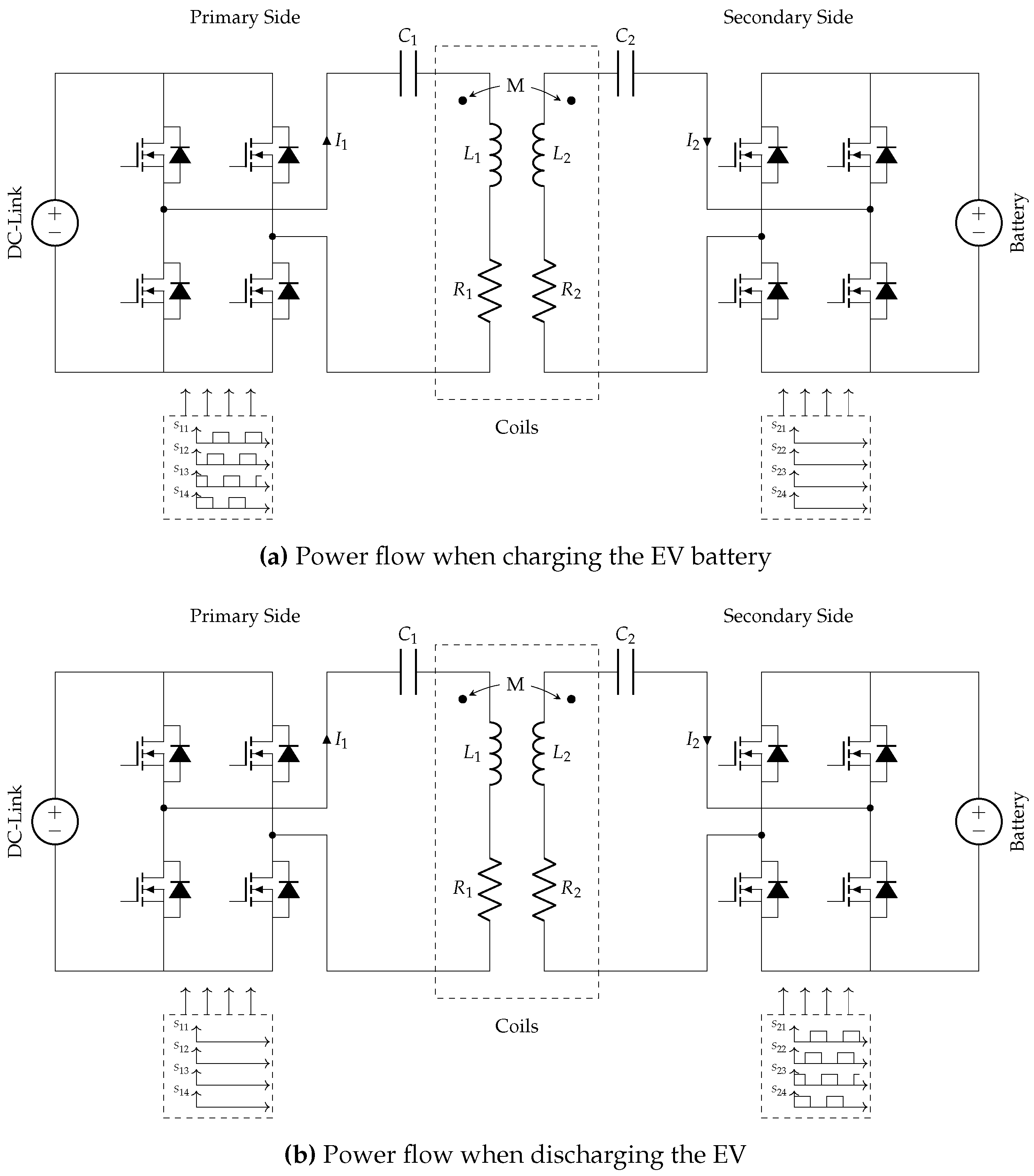
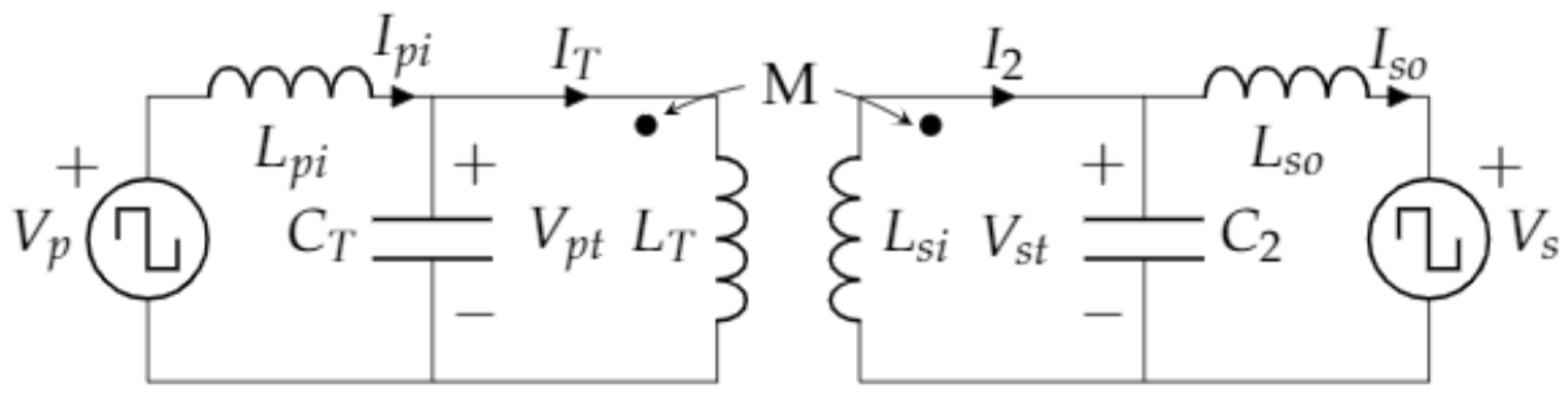
3. Model for EV Bidirectional Wireless Charger

A generic structure of a wireless charger consists of two air-coupled coils. The primary coil, which is installed on the pavement, is traversed with a time-varying current so that the generated magnetic field powers a secondary coil (typically placed underneath the vehicle’s chassis). Compensation networks are connected to both coils in order to maximise the output power transfer and efficiency. There are four uni-resonant topologies for the compensation network (Series-Series, Series-Parallel, Parallel-Parallel and Parallel-Series) and some popular high-order compensation networks (mainly LCC and LCL). In EV bidirectional wireless chargers, the proposed implementations rely on compensation networks with the same structure on the primary and the secondary side so that the control is similar for both power flows.
The EV wireless charger also have some power converters on the primary and the secondary sides. On the primary side, when it is delivering power to the battery, there is a rectification process that may be enhanced with a power factor correction. Then, the generated DC signal is the input of a DC/AC converter. This converter is usually performed using a full-bridge inverter [42,43,44,45], but there are some other topologies, such as single-ended converters [46] or multi-phase systems [47,48]. Some authors choose to include a DC/DC converter between the grid rectifier and the primary inverter. This option prevents the inverter from having to adjust the output voltage and enables operation in ZVS [49].
The secondary charger includes a rectifier to adapt the high-frequency current to the DC used by the battery. A diode-based rectifier is sufficient to perform this function, but charging regulation on this side of the charger is limited. This limitation can be overcome by installing a DC/DC converter [50,51] or a controlled rectifier that, depending on its topology, allows the flow of energy in both directions. Both options work as a battery impedance adapter [52], which helps with a suitable control strategy to improve the efficiency of the process [53].
Figure 3 shows the generic structure of an EV wireless charger. The structure from the primary DC/AC converter to the secondary AC/DC converter constitutes a Dual Active Bridge (DAB) [54]. It can be observed that the power converters are operated according to the instructions sent by the controllers. In bidirectional chargers, controllers are installed in both sets of power converters. For their operation, they may require the data acquired on the other side so a communication channel is established between the two controllers.
For a bidirectional wireless charger, the effects of the power converters are included in a simplified circuit as two AC sources ( V p and V s ), which is represented in Figure 4. The source V p represents the output voltage of the primary DC/AC converter. Specifically, the compensation networks are adjusted so that the First Harmonic Approximation is valid. Consequently, V p corresponds to the fist harmonic of the out of the primary DC/AC converter. The source V s models the battery voltage once it has been converter by the secondary power converter into AC. When studying uni-directional wireless charger, the battery is usually modelled as an equivalent resistance. However, for bidirectional wireless charger the battery must be replaced by an equivalent voltage source.

4. V2G Control Techniques

The control applied to V2G-enabled wireless chargers is strongly dependent on the configuration of the power converters that they have. In this sense, we can divided the proposed structures into two main categories. Each category and the description of the control strategies are described next.

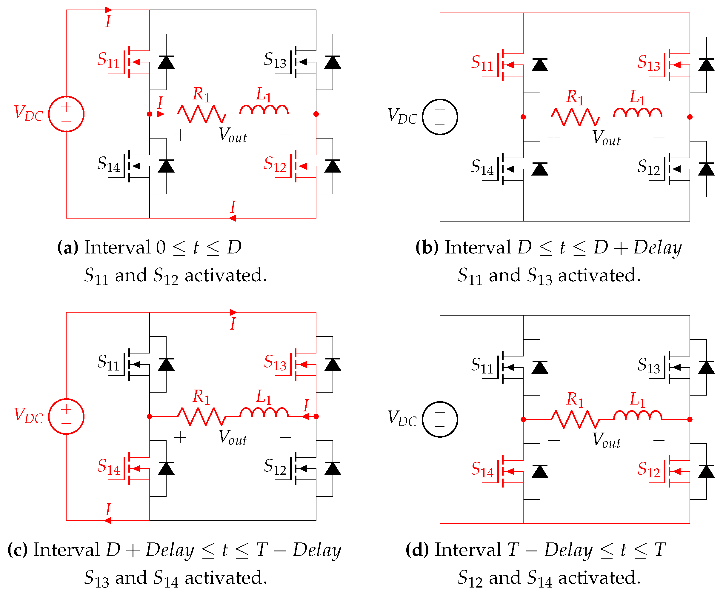
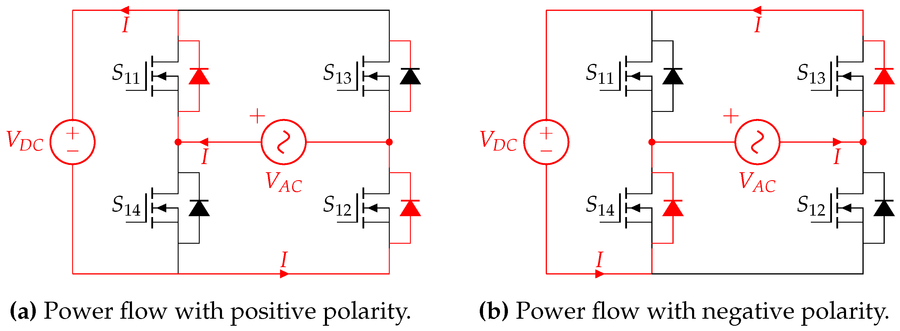
4.1. Activation of the Power Converters

Power-converters in bidirectional wireless chargers are implemented as bidirectional. Bidirectional power converters usually have a different performance when they are activated or deactivated. Figure 5 shows the typical power converter used in this kind of charger. It is a full-bridge DC/AC converter in which the transistors are also connected with antiparallel diodes. Please note that SiC MOSFETs devices includes intrinsic body diodes, which eliminates the need of using anti-parallel diodes for current freewheeling [55], although SiC Schottky diodes are usually included to improve the performance [56]. SiC MOSFETs are usually employed in wireless chargers to comply with the requirements of the operational frequency and the power levels [57].
When actively operated, only one semiconductor in each leg is activated, being four, the potential states of the power converter in a phase-shifting control. Figure 6 illustrates the operation modes. In Figure 7, we have plotted the output voltage V o u t of the converter with a phase-shift control.
Alternatively, if no control is applied, the power converter operates as a rectifier so that the current traverses the diodes. The power flow is illustrated in Figure 8.
Considering this dual performance, simple approaches implement bidirectional wireless chargers by using two bidirectional power converters (one on the primary side and another on the secondary side) but activating only one of them. When the activated converter is the one on the primary side, the converter connected to the grid must be operated as a rectifier, and the output DC is converted again by the primary DC/AC converter. Thus, when the power must flow from the grid to the battery, the primary converter is controlled with a typical phase-shifting modulation, and the seconder converter has all its transistors deactivated to operate as a rectifier. This operation is reflected in Figure 9a. On the other hand, when the activated converter is the one on the secondary side, the power flows from the battery to the grid. In order for this to happen, the secondary AC/DC converter must operate as an inverter, while the primary AC/DC converter works as a rectifier. The discharging operation is presented in Figure 9b.
In this approach, the flow of the active power is easily adjusted, and the expected efficiency can be computed as in [58]. There must be coordination between the power converters to set the configuration in both controllers. A wireless communication channel may be established for this purpose, but the delay in processing the signal is not a limiting feature. Thus, both controllers can be easily configured and coordinated. However, it is not evident how to control the reactive power flow.

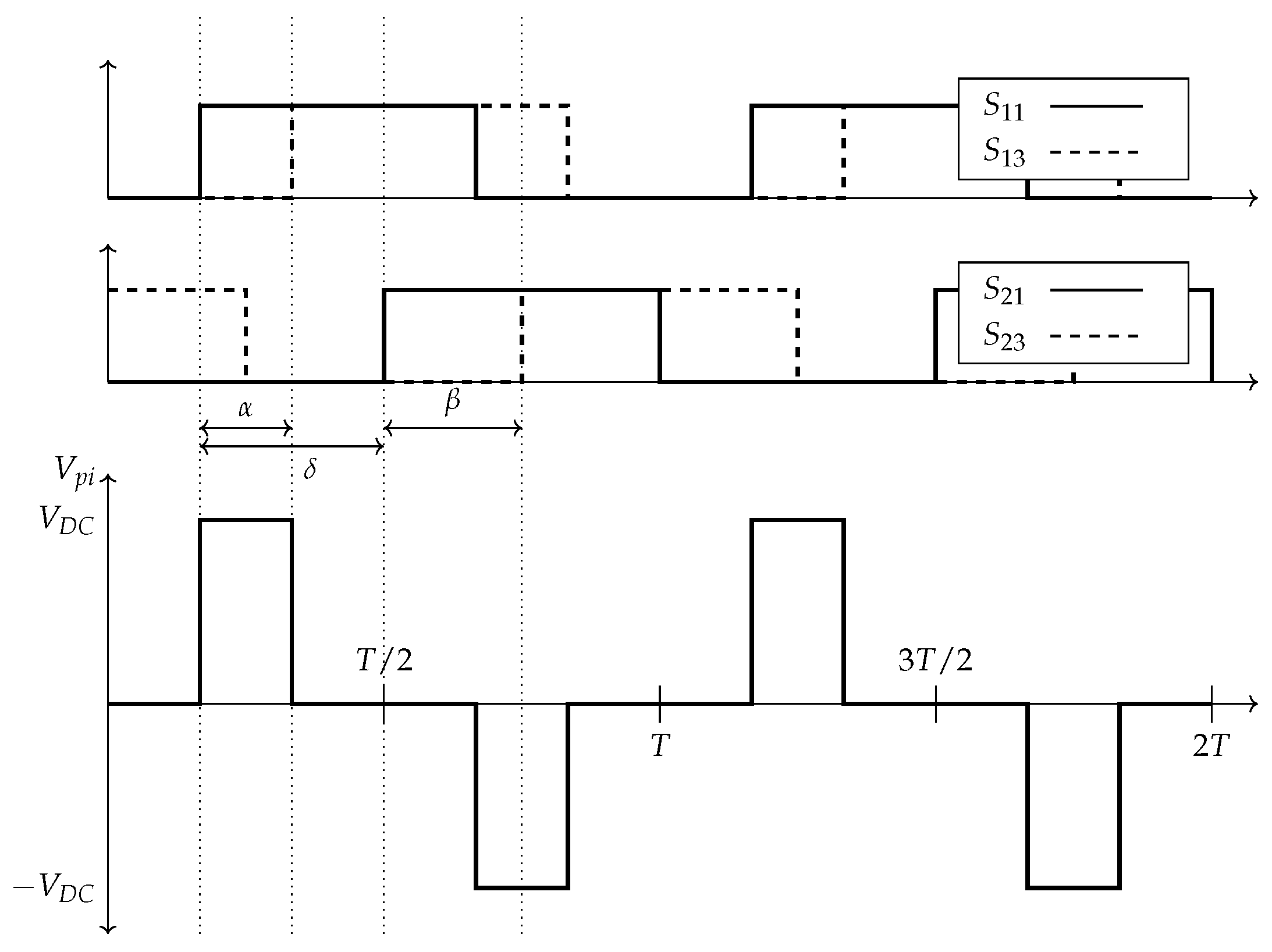
4.2. Phase-Delay between the Power Converters

Based on two full-bridge power converters for the primary and the secondary sides, they can be both simultaneously activated but forcing a delay in the switching signals of the semiconductors on the secondary side in comparison with those used on the primary side. Figure 10 shows the activation signals of the semiconductors of the power converters, where α and β are the phase angle of the primary and secondary AC/DC converter, respectively. As can be observed, there is a delay δ between both signals. The delay δ allows for controlling the sense of the power flow. As this technique is usually implemented with phase-shifting, the angles α and β adjust the power level flowing from both sides.
With these activation signals, the first harmonic of the output voltages of both converters ( v p and v s ) are expressed as:
v p ( t ) = 4 π V p n = 1 , 3 , 1 n cos n w r t n α 2 sin n α 2
v s ( t ) = 4 π V s n = 1 , 3 , 1 n cos n w r t n α 2 + n δ sin n β 2
where α and β are the phase shift between each pair of transistors of each inverter, δ is the phase shift between the primary and secondary inverter peak voltages ( V p and V s ), and n is the harmonic order.
With a mesh-based analysis, it is possible to derive the active and the reactive power. If we use a first-harmonic approximation, we can get the following equations for the power in a Series-Series configuration:
P s = 8 π 2 · M · ω R 1 R 2 + M 2 ω 2 V p V s sin α 2 sin β 2 sin δ
Q s = 8 π 2 · M · ω R 1 R 2 + M 2 ω 2 V p V s s i n α 2 sin β 2 cos δ
In a similar approach, we can obtain the equations about the power in a LCL-LCL configuration, as the one represented in Figure 11. This configuration is obtained by inserting additional coils in series on both sides of a PP compensation topology.
For a topology in which L p i = L T and L s i = L s o , the two terms of the power generated by the battery are:
P s = 8 π 2 · M · γ ω r L p i L s o V p V s sin α 2 sin β 2 sin δ
Q s = 8 π 2 · M · γ ω r L p i L s o V p V s sin α 2 sin β 2 cos δ
where γ is a constant whose value is so close to unity and is given by γ = L p i L s o ( L p i + C T R T R p i ) ( L s o + C 2 R s i R s o ) + w r 2 M 2 C 2 C T R p i R s o , L p i and L s o are the inductives located in the primary and secondary inverter outputs, respectively, R p i and R s o are the resistors of L p i and L s o , respectively, L T and L s i are the inductives located in the coupler, and R T and R s i are similar to R p i and R s o , but they are associated to L T and L s i , respectively.
For the LCC-LCC configuration (in Figure 12), the power equations that we can obtain are:
P s = 8 π 2 · M ω r L p i L s o V p V s cos α 2 cos β 2 sin δ
Q s = 8 π 2 · M ω r L p i L s o V p V s cos α 2 cos β 2 cos δ
From the previous equations, we can observe that there are three methods to configure the power flow. The first one consists of keeping a fixed δ and adjusting the voltages V p and V s by the parameters α and β , respectively. As pointed out by [59], with this approach, it is not necessary to synchronise the two power converters, but it usually results in a lower efficiency. The second one consists of tuning the value of δ based on a synchronisation method between primary and secondary converters. Some control approaches opt for achieving a unity power factor. To do so, δ is set equal to ± 90 by the controller for the three compensation networks analysed before. The flow of power is decided by the sign of this parameter. So, if δ is + 90 , power flows from the battery to the grid, which corresponds to mode II. When δ is 90 , power flows from the grid to the vehicle, that is, there is a charging process, which is modelled by mode I. If the sense of the power flow and the power level are both adjusted, we need to configure two or three of this scheme’s parameters.

5. Descriptive Works on V2G Control

In the related literature, we can find several proposals for V2G control in wireless chargers. When analysing them, we should focus on the following properties:
  • Control technique applied, that is, if controllable activation/deactivation of the power converters is used or whether a phase-delay in the activation of these structures is configured.
  • The range of adjustment for P and/or Q, and if the setpoint restricts one power once, the other is tuned.
Considering these features, the most relevant works on V2G control are analysed in this Section. The study is grouped into two main parts, associated with the control technique described previously. As for the technique consisting in the activation/deactivation of the power converters, we have identified the following papers. The authors in [60] use two full-bridge converters. For each sense of the power flow, there are four modes in which one of the converter activates the transistors and the other one uses the antiparallel diodes. PWM is employed to adjust the power levels. A PWM signal is also used in [61] to adjust the power and the frequency of the switching signals of the active power converter. The implementation is done for a unidirectional power flow, but the authors state that the bidirectional power flow can be effectively achieved by replicating the designed control on the secondary side. In both works, only the active power flow is considered. The work in [62] also sets a target for an active power by adjusting the duty cycle of an eight-switching leg. The operational frequency is also tuned to make the system operate in resonance, so that reactive power is minimized.
The work in [63] proposes an asymmetrical structure for the compensation networks. Assuming that most power flow will be from the grid to the battery, they optimise the performance of the primary side by introducing a capacitor in parallel to a LC tank. This capacitor is intended to minimise the high leakage of the primary coil. The power converters (half-bridge with two switches per leg) on the primary and secondary side are alternatively activated according to the power flow. The controller sets a reference power and the switching of the transistors is executed to achieve a Zero Voltage Switching (ZVS). No setting is imposed on the reactive power.
In [64], we can find a study about how to configure the ferromagnetic material in two circular coils used in an e-bike wireless charger. As for the control, when charging the battery, the Constant Voltage and Constant Current modes are implemented. When discharging the battery, a current control based on the variation of the operational frequency is applied. Only modes I and II in the four-quadrant diagram are considered.
Table 1 summarizes the main features of these control systems with switched activation of the converters.
One of the preliminary works dealing with phase delay in the power converters for controlling the power was presented in [65]. This document details a control algorithm to modify the active and the reactive power consumed by the set DC-DC converter plus battery. It also sets the goal of maximising efficiency by adjusting the operational parameters of a synchronous rectifier and the DC/DC converter on the secondary side. Specifically, the work develops the theoretical model for a Series-Series wireless charger, in which the secondary side has a variable load. The variation of the load is the result of the adjustment of the above-mentioned power converters. In the secondary rectifier, the authors use the phase-shifting ( δ ) and the phase-delay ( ϕ ) to adjust the power delivered to the load. The duty-cycle of the DC-DC converter is also tuned to optimise the efficiency of the power transfer. The authors have tested the proposed algorithm for a positive power delivered to the battery, but the solution is also valid for other quadrants. There is no study about the reactive power, which is also modified according to the parameters.
The authors in [66] propose a control applied to an EV wireless charger with an AC/DC and a DC/DC converter on the secondary side too. Thus, there are two DC-links, and the control adjusts the voltage on both capacitors to set the sense of the power flow. In addition, it adjusts the EV battery current.
The authors in [67] propose that the operational frequency deviates from the resonant one if the power needs to be adjusted (please note that frequency is inversely proportional to P and Q). A droop-control is proposed to set the operational frequency while keeping δ to ± 90 according to the sense of the power flow. As the previous equations are not valid when the system does not work at resonance, reactive power is also transferred, but its impact is low. Setting this phase delay is common for other proposals. In this sense, the work in [68] presents a control algorithm installed on the pick-up side. The phase delay between the primary and the secondary converters is set to 90 or 90 as the goal of the paper is to control the active power flow and its level with a null reactive power. Thus, there is a PI-controller to adjust the phase delay between the two controllers with the goal of having a power factor equal to 1. Then, the phase shift of the primary and the secondary sides are set with another PI controller computing the difference between the measured power and the reference power to reach.
In [69], the authors propose an EV bidirectional wireless charger connected to the grid and to the home. With a phase shifting and a phase delay, the power flow and the power level are controlled in the wireless charger. The control is executed in the first converter in the wireless charger connected to these two systems. It is referred to as Power Quality Control Converter (PQCC). It operates by setting the phase delay to 90 or to 90 , as they want to minimise the reactive power. Then, the voltage in the DC link is controlled by this power converter as it is directly related to the power amount that the charger consumes or generates. Phase angle in the primary and secondary converters are set equal.
Focusing on transferring active power, the analysis presented in [70] describes how to set the ratio between the primary and the secondary voltages in order to maximise the efficiency of this process. The authors conclude that the ratio should be one. As presented, the maximum efficiency is related to the phase delay between both converters. In order to incorporate the effects of the components’ tolerance, the exact value of the phase delay is set with an iterative algorithm in which the initial value of the phase delay is the theoretical maximum one. Reactive power is not analysed explicitly for this tuning. With a similar strategy, the work in [71] uses a Model Predictive control to configure the phase shifting of the primary and the secondary converters in order to maximise the efficiency of the active power transfer. The flow of the reactive power is set to null as the phase delay of the power converters is ± 90 , being the sign related to the sense of the power flow. The same angles are kept in Ref. [72]. The goal of the controller is to get a reference current flowing in the battery so that the α and β angles are adjusted for this purpose. The work in [73] addresses which configuration of α and β are the most convenient one in order to work with Zero Phase Angle (ZPA), as the optimisation oriented to maximum efficiency is assumed to be too complex and it cannot be executed in real-time.
A different approach is presented in [59]. In this work, the authors opt for deciding the sense of the power flow according to a target current on the secondary side. Therefore, by measuring the difference with this parameter and using a PI controller, they decide the δ value.
The work in [74] focuses on the effects of the delay in the wireless communication system. As described in this paper, the delay is not negligible when compared with the switching periods of this kind of system. Thus, the power converters on the primary and on the secondary side must be controlled, assuming this additional delay. As the delay in a communication channel is variable, the authors propose the observation of the output current, which is mathematically related to this delay. By slightly increasing/reducing the value of this delay, the controller can identify if the current is the maximum one, which will correspond to the target state for this proposal.
The previous approaches are oriented to get a predefined active power. However, reactive power is also necessary for some V2X services as described in Section 2. Considering this need, a bilayer algorithm is proposed in [75] for bidirectional wireless chargers of Electric Vehicles integrated with the grid, with the home or another vehicle. The first layer captures the data about the surrounding infrastructure to which the EV is connected. With this information (market prices, state, etc.), the layer decides the optimal reference signals (target P and Q) that should achieve the charger. The second layer decides the configuration parameters of the primary and the secondary converters to get to the target power. This second layer relies on a mathematical model of the power in an LCL-LCL wireless charger, but other compensation networks are feasible with the modelling presented in [76]. According to these models, both types of power can be configured with a phase delay between the two power converters. The description of the design of the coils can be found in Ref. [77].
Table 2 summarizes the features of the most relevant V2G controllers for wireless chargers applying a phase delay between the two power converters.
It can be observed that the V2G controllers rely on the same compensation network on the primary and on the secondary sides. This coincidence eases the control configuration. Full-bridge topologies are mostly used for these systems.

6. Future Trends and Challenges

To promote the use of V2G wireless controllers, there are still some open issues that must be addressed. Some of them are common with on-board conductive chargers [78], but others are specific for wireless chargers due to the challenges imposed by the wireless power transfer technology. The most significant challenges to achieve fully operative V2G wireless chargers are:
  • Harmonic restriction. The controller must activate and deactivate the switching devices taking into account that the whole system must comply with the harmonic recommendations described in IEEE-519. The consideration of the switching technique when designing the EMI filter could reduce the overall cost of the system and improve its performance.
  • Coupler design. Little attention has been paid to the coil design in bidirectional wireless chargers, with just some proposals in [64,77] addressing this topic. Since the power flow is in both senses, the coil design must attend to the magnetic field leakage and variations of the coupling coefficient due to misalignment for the battery charging and discharging process.
  • Switching devices. SiC MOSFETs is the predominant choice for bidirectional wireless chargers due to power capability and the supported switching frequency. In order to increase the efficiency of the system, all the diodes are fast body diodes. How to effectively generate the gate signals is still a non-trivial ask as there must be synchronized with other legs in the power converter and even with those in the other power converter [78].
  • Synchronisation of the power converters. Achieving precise coordination between the two power converters in real-time must be studied in practical implementations. As stated in [74], the communication delay must be considered with phase-delay approaches. A statistical characterisation of the delay or the use of communication models may be the adequate strategy to incorporate the effects of a typically variable delay in the communication system used between the primary and the secondary sides.
  • Synchronisation with the grid. To date, most studies works with the reduced equivalent circuit of the wireless charger. However, if we want to adjust P and Q in the grid interface, we must consider the fact that the grid phase impacts the power factor of the energy delivered to the grid, and consequently, it must be included in the design of the V2G controllers too. Some works on bidirectional conductive chargers base the control on the voltage difference between the grid and the charger. Similar approaches must be deeply studied in the context of wireless chargers.
  • Full four-quadrant operation of the system with maximum efficiency. We have observed that there are some works that configure the controller to maximise the efficiency of the power transfer for modes I and II. This optimisation should be extended for other controllers dealing with more operation modes.
The fulfilment of these challenges are foreseen as the future main trends on the development of V2G wireless chargers.

7. Conclusions

EVs must be complemented with the correct charger infrastructure in order to ensure an effective operation in the Smart Grid. In this sense, wireless chargers, which provide convenient advantages for an autonomous operation, should deploy the technology to facilitate that EVs could provide ancillary services. Towards this goal, the power flow of active and reactive power should be controlled, and the control algorithms should be properly designed. This paper describes how V2G control has been applied in these systems. With the presented study, we identify that there are two main techniques to perform V2G control. The first one consists of the activation and the deactivation of the power converter on the primary and on the secondary side according to the sense of the power flow. The second approach deals with the two power converters activated but with a relative phase delay. The magnitude and sign of the phase delay adjust the power level and its sense. The coordination between the two converters to achieve a specific delay is not trivial at the operational frequencies. There is a significant number of works dealing with the sense of the power flow in EV wireless chargers within the two types of techniques. However, how to efficiently and simultaneously control P and Q remains a goal as there are limited proposals oriented to this objective. We can observe that the compensation networks are mostly the same on the primary and the secondary side. As for the power converters, most proposals opt for full-bridge converters on the primary and on the secondary sides.
Open issues still remain to fulfil complete bidirectional wireless chargers as exposed in the paper.

Author Contributions

Conceptualisation, A.T. and J.M.G.-G.; methodology, A.T. and J.M.G.-G.; formal analysis, M.C. and A.T.; writing—original draft preparation, A.T., J.M.G.-G. and M.C.; writing—review and editing, A.T., J.M.G.-G. and M.C.; visualisation, M.C.; supervision, A.T.; project administration, A.T.; funding acquisition, A.T. All authors have read and agreed to the published version of the manuscript.

Funding

Funding for this project was partially provided by the Spanish Ministerio de Ciencia e Innovacion (MICINN) project PID2019-110531-RA-I00 from the “Proyectos de I+D+i-RTI Tipo A”.

Conflicts of Interest

The authors declare no conflict of interest.

References

  1. United States Environmental Protection Agency. Sources of Greenhouse Gas Emissions. Available online: https://www.epa.gov/ghgemissions/sources-greenhouse-gas-emissions (accessed on 16 June 2021).
  2. Khan, S.U.; Mehmood, K.K.; Haider, Z.M.; Bukhari, S.B.A.; Lee, S.J.; Rafique, M.K.; Kim, C.H. Energy management scheme for an EV smart charger V2G/G2V application with an EV power allocation technique and voltage regulation. Appl. Sci. 2018, 8, 648. [Google Scholar] [CrossRef] [Green Version]
  3. Wang, K.; Gu, L.; He, X.; Guo, S.; Sun, Y.; Vinel, A.; Shen, J. Distributed Energy Management for Vehicle-to-Grid Networks. IEEE Netw. 2017, 31, 22–28. [Google Scholar] [CrossRef]
  4. Janjic, A.; Velimirovic, L.; Stankovic, M.; Petrusic, A. Commercial electric vehicle fleet scheduling for secondary frequency control. Electr. Power Syst. Res. 2017, 147, 31–41. [Google Scholar] [CrossRef]
  5. Triviño-Cabrera, A.; Aguado, J.A.; de la Torre, S. Joint routing and scheduling for electric vehicles in smart grids with V2G. Energy 2019, 175, 113–122. [Google Scholar] [CrossRef]
  6. Navigant. Available online: http://www.navigantresearch.com/research/wireless-power (accessed on 16 June 2021).
  7. He, T.; Lu, D.D.C.; Wu, M.; Yang, Q.; Li, T.; Liu, Q. Four-Quadrant Operations of Bidirectional Chargers for Electric Vehicles in Smart Car Parks: G2V, V2G, and V4G. Energies 2020, 14, 181. [Google Scholar] [CrossRef]
  8. Triviño, A.; González-González, J.M.; Aguado, J.A. Wireless Power Transfer Technologies Applied to Electric Vehicles: A Review. Energies 2021, 14, 1547. [Google Scholar] [CrossRef]
  9. Sharma, A.; Sharma, S. Review of Power Electronics in Vehicle-to-Grid Systems. J. Energy Storage 2019, 21, 337–361. [Google Scholar] [CrossRef]
  10. Global EV Outlook 2020. Wireless EV Charging Market Share, Size and Industry Growth Analysis 2020 632-2025; Technical Report; IndustryARC: Hyderabad, India, 2020.
  11. Global EV Outlook 2020; Technical Report; International Energy Agency: Paris, France, 2020.
  12. Shao, S.; Pipattanasomporn, M.; Rahman, S. Grid Integration of Electric Vehicles and Demand Response with Customer Choice. IEEE Trans. Smart Grid 2012, 3, 543–550. [Google Scholar] [CrossRef]
  13. Albadi, M.H.; El-Saadany, E.F. Demand response in electricity markets: An overview. In Proceedings of the 2007 IEEE Power Engineering Society General Meeting, PES, Tampa, FL, USA, 24–28 June 2007. [Google Scholar] [CrossRef]
  14. Li, Y.; Yu, G.; Liu, J.; Deng, F. Design of V2G auxiliary service system based on 5G technology. In Proceedings of the 2017 IEEE Conference on Energy Internet and Energy System Integration, EI2 2017-Proceedings, Beijing, China, 26–28 November 2017; Institute of Electrical and Electronics Engineers Inc.: Piscataway, NJ, USA, 2017; pp. 1–6. [Google Scholar] [CrossRef]
  15. Gago, R.G.; Pinto, S.F.; Silva, J.F. G2V and V2G electric vehicle charger for smart grids. In Proceedings of the IEEE 2nd International Smart Cities Conference: Improving the Citizens Quality of Life, ISC2 2016-Proceedings, Trento, Italy, 12–15 September 2016; Institute of Electrical and Electronics Engineers Inc.: Piscataway, NJ, USA, 2016. [Google Scholar] [CrossRef]
  16. Clement-Nyns, K.; Haesen, E.; Driesen, J. The impact of Charging plug-in hybrid electric vehicles on a residential distribution grid. IEEE Trans. Power Syst. 2010, 25, 371–380. [Google Scholar] [CrossRef] [Green Version]
  17. Masoum, M.A.; Moses, P.S.; Hajforoosh, S. Distribution transformer stress in smart grid with coordinated charging of plug-in electric vehicles. In Proceedings of the 2012 IEEE PES Innovative Smart Grid Technologies, ISGT 2012, Washington, DC, USA, 16–20 January 2012. [Google Scholar] [CrossRef] [Green Version]
  18. Clement, K.; Haesen, E.; Driesen, J. Coordinated charging of multiple plug-in hybrid electric vehicles in residential distribution grids. In Proceedings of the 2009 IEEE/PES Power Systems Conference and Exposition, PSCE 2009, Seattle, WA, USA, 15–18 March 2009. [Google Scholar] [CrossRef]
  19. Sortomme, E.; Hindi, M.M.; MacPherson, S.D.; Venkata, S.S. Coordinated charging of plug-in hybrid electric vehicles to minimize distribution system losses. IEEE Trans. Smart Grid 2011, 2, 198–205. [Google Scholar] [CrossRef]
  20. Mets, K.; Verschueren, T.; De Turck, F.; Develder, C. Exploiting V2G to optimize residential energy consumption with electrical vehicle (dis)charging. In Proceedings of the 2011 IEEE 1st International Workshop on Smart Grid Modeling and Simulation, SGMS 2011, Brussels, Belgium, 17 October 2011; pp. 7–12. [Google Scholar] [CrossRef] [Green Version]
  21. Pimm, A.J.; Cockerill, T.T.; Taylor, P.G. The potential for peak shaving on low voltage distribution networks using electricity storage. J. Energy Storage 2018, 16, 231–242. [Google Scholar] [CrossRef]
  22. Uddin, K.; Dubarry, M.; Glick, M.B. The viability of vehicle-to-grid operations from a battery technology and policy perspective. Energy Policy 2018, 113, 342–347. [Google Scholar] [CrossRef]
  23. Joy, E.R.; Thirugnanam, K.; Singh, M.; Kumar, P. Distributed active and reactive power transfer for voltage regulation using V2G system. In Proceedings of the 2015 4th International Conference on Electric Power and Energy Conversion Systems, EPECS 2015, Sharjah, United Arab Emirates, 24–26 November 2015; Institute of Electrical and Electronics Engineers Inc.: Piscataway, NJ, USA, 2015. [Google Scholar] [CrossRef]
  24. Wirasanti, P. Ancillary Services Analysis based on Multiple-Area of V2G Operation-Frequency Regulation Service. In Proceedings of the IECON Proceedings (Industrial Electronics Conference), IEEE Computer Society, Lisbon, Portugal, 14–17 October 2019; pp. 2132–2137. [Google Scholar] [CrossRef]
  25. Calearo, L.; Marinelli, M. Profitability of frequency regulation by electric vehicles in Denmark and Japan considering battery degradation costs. World Electr. Veh. J. 2020, 11, 48. [Google Scholar] [CrossRef]
  26. Bañol Arias, N.; Hashemi, S.; Andersen, P.B.; Træholt, C.; Romero, R. Assessment of economic benefits for EV owners participating in the primary frequency regulation markets. Int. J. Electr. Power Energy Syst. 2020, 120, 105985. [Google Scholar] [CrossRef]
  27. Gschwendtner, C.; Sinsel, S.R.; Stephan, A. Vehicle-to-X (V2X) implementation: An overview of predominate trial configurations and technical, social and regulatory challenges. Renew. Sustain. Energy Rev. 2021, 145, 110977. [Google Scholar] [CrossRef]
  28. Andersen, P.B.; Toghroljerdi, S.H.; Sørensen, T.M.; Christensen, B.E.; Morell, J.C.; Høj, L.; Zecchino, A.; Olesen, O.J.; Due, A. The Parker Project-Final Report; Technical Report; Parker Hannifin: Cleveland, OH, USA, 2019. [Google Scholar]
  29. Nissan Motor Corporation. Nissan, E.ON Drive and Imperial College Highlight the Carbon Saving and Economic Benefits of Vehicle-to-Grid Technology. Available online: https://europe.nissannews.com/en-GB/releases/release-beb6420a9f2916baf13a4ed15006b51d-nissan-eon-drive-and-imperial-college-highlight-the-carbon-saving-and-economic-benefits-of-vehicle-to-grid-technology (accessed on 22 July 2021).
  30. Fachrizal, R.; Munkhammar, J. Improved photovoltaic self-consumption in residential buildings with distributed and centralized smart charging of electric vehicles. Energies 2020, 13, 1153. [Google Scholar] [CrossRef] [Green Version]
  31. Dagdougui, H.; Ouammi, A.; Dessaint, L.A. Peak Load Reduction in a Smart Building Integrating Microgrid and V2B-Based Demand Response Scheme. IEEE Syst. J. 2019, 13, 3274–3282. [Google Scholar] [CrossRef]
  32. Knezovic, K.; Marinelli, M.; Moller, R.J.; Andersen, P.B.; Traholt, C.; Sossan, F. Analysis of voltage support by electric vehicles and photovoltaic in a real Danish low voltage network. In Proceedings of the Universities Power Engineering Conference, IEEE Computer Society, Cluj-Napoca, Romania, 2–5 September 2014. [Google Scholar] [CrossRef] [Green Version]
  33. Nguyen, H.N.; Zhang, C.; Mahmud, M.A. Optimal Coordination of G2V and V2G to Support Power Grids with High Penetration of Renewable Energy. IEEE Trans. Transp. Electrif. 2015, 1, 188–195. [Google Scholar] [CrossRef]
  34. Barone, G.; Buonomano, A.; Forzano, C.; Giuzio, G.F.; Palombo, A. Increasing self-consumption of renewable energy through the Building to Vehicle to Building approach applied to multiple users connected in a virtual micro-grid. Renew. Energy 2020, 159, 1165–1176. [Google Scholar] [CrossRef]
  35. Tchagang, A.; Yoo, Y. V2B/V2G on energy cost and battery degradation under different driving scenarios, peak shaving, and frequency regulations. World Electr. Veh. J. 2020, 11, 14. [Google Scholar] [CrossRef] [Green Version]
  36. Liu, C.; Chau, K.T.; Wu, D.; Gao, S. Opportunities and challenges of vehicle-to-home, vehicle-to-vehicle, and vehicle-to-grid technologies. Proc. IEEE 2013, 101, 2409–2427. [Google Scholar] [CrossRef] [Green Version]
  37. Wang, X.; Liu, Y.; Qian, W.; Wang, B.; Lu, X.; Zou, K.; González-Santini, N.; Karki, U.; Peng, F.Z.; Chen, C. A 25 kW SiC Universal Power Converter Building Block for G2V, V2G, and V2L Applications. In Proceedings of the 2018 IEEE International Power Electronics and Application Conference and Exposition, PEAC 2018, Shenzhen, China, 4–7 November 2018; Institute of Electrical and Electronics Engineers Inc.: Piscataway, NJ, USA, 2018. [Google Scholar] [CrossRef]
  38. Sovacool, B.K.; Kester, J.; Noel, L.; Zarazua de Rubens, G. Actors, Business Models, and Innovation Activity Systems for Vehicle-to-Grid (V2G) Technology: A Comprehensive Review. Renew. Sustain. Energy Rev. 2020, 131, 109963. [Google Scholar] [CrossRef]
  39. Escudero-Garzas, J.J.; Garcia-Armada, A.; Seco-Granados, G. Fair design of plug-in electric vehicles aggregator for V2G regulation. IEEE Trans. Veh. Technol. 2012, 61, 3406–3419. [Google Scholar] [CrossRef] [Green Version]
  40. Sun, S.; Dong, M.; Liang, B. Real-time welfare-maximizing regulation allocation in dynamic aggregator-EVs system. IEEE Trans. Smart Grid 2014, 5, 1397–4109. [Google Scholar] [CrossRef] [Green Version]
  41. Han, S.; Han, S.; Sezaki, K. Estimation of achievable power capacity from plug-in electric vehicles for V2G frequency regulation: Case studies for market participation. IEEE Trans. Smart Grid 2011, 2, 632–641. [Google Scholar] [CrossRef]
  42. Miller, J.M.; Onar, O.C.; Chinthavali, M. Primary-side power flow control of wireless power transfer for electric vehicle charging. IEEE J. Emerg. Sel. Top. Power Electron. 2015, 3, 147–162. [Google Scholar] [CrossRef]
  43. Thrimawithana, D.J.; Madawala, U.K. A primary side controller for inductive power transfer systems. In Proceedings of the IEEE International Conference on Industrial Technology, Via del Mar, Chile, 14–17 March 2010; pp. 661–666. [Google Scholar] [CrossRef]
  44. Triviño-Cabrera, A.; Ochoa, M.; Fernández, D.; Aguado, J.A. Independent primary-side controller applied to wireless chargers for electric vehicles. In Proceedings of the 2014 IEEE International Electric Vehicle Conference, IEVC 2014, Florence, Italy, 17–19 December 2014; Institute of Electrical and Electronics Engineers Inc.: Piscataway, NJ, USA, 2014. [Google Scholar] [CrossRef] [Green Version]
  45. González-González, J.M.; Triviño-Cabrera, A.; Aguado, J.A. Design and validation of a control algorithm for a SAE J2954-compliant wireless charger to guarantee the operational electrical constraints. Energies 2018, 11, 604. [Google Scholar] [CrossRef] [Green Version]
  46. Omori, H.; Iga, Y.; Morizane, T.; Kimura, N.; Nakagawa, K.; Nakaoka, M. A novel wireless EV charger using SiC single-ended quasi-resonant inverter for home use. In Proceedings of the 15th International Power Electronics and Motion Control Conference and Exposition, EPE-PEMC 2012 ECCE Europe, Novi Sad, Serbia, 4–6 September 2012. [Google Scholar] [CrossRef]
  47. Deng, Q.; Wang, Z.; Chen, C.; Czarkowski, D.; Kazimierczuk, M.K.; Zhou, H.; Hu, W. Modeling and control of inductive power transfer system supplied by multiphase phase-controlled inverter. IEEE Trans. Power Electron. 2019, 34, 9303–9315. [Google Scholar] [CrossRef]
  48. Vu, V.B.; Dahidah, M.; Pickert, V.; Phan, V.T. A High-Power Multiphase Wireless Dynamic Charging System with Low Output Power Pulsation for Electric Vehicles. IEEE J. Emerg. Sel. Top. Power Electron. 2020, 8, 3592–3608. [Google Scholar] [CrossRef] [Green Version]
  49. Chen, C.; Zhou, H.; Deng, Q.; Hu, W.; Yu, Y.; Lu, X.; Lai, J. Modeling and Decoupled Control of Inductive Power Transfer to Implement Constant Current/Voltage Charging and ZVS Operating for Electric Vehicles. IEEE Access 2018, 6, 59917–59928. [Google Scholar] [CrossRef]
  50. Gonzalez-Gonzalez, J.M.M.; Trivino, A.; Aguado, J.A. Model Predictive Control to Maximize the Efficiency in EV Wireless Chargers. IEEE Trans. Ind. Electron. 2021. [Google Scholar] [CrossRef]
  51. Wu, H.H.; Gilchrist, A.; Sealy, K.D.; Bronson, D. A high efficiency 5 kW inductive charger for EVs using dual side control. IEEE Trans. Ind. Inform. 2012, 8, 585–595. [Google Scholar] [CrossRef] [Green Version]
  52. Corti, F.; Reatti, A.; Nepote, A.; Pugi, L.; Pierini, M.; Paolucci, L.; Grasso, F.; Grasso, E.; Nienhause, M. A secondary-side controlled electric vehicle wireless charger. Energies 2020, 13, 6527. [Google Scholar] [CrossRef]
  53. Zhong, W.X.; Hui, S.Y. Maximum energy efficiency tracking for wireless power transfer systems. IEEE Trans. Power Electron. 2015, 30, 4025–4034. [Google Scholar] [CrossRef] [Green Version]
  54. Cui, C.; Liu, Y.; Pehrman, D.; Huang, X.; Zhang, Q. A Full Power Range ZVS Control Technology for Bidirectional Inductive Power Transfer System. In Proceedings of the IECON Proceedings (Industrial Electronics Conference), IEEE Computer Society, Singapore, 18–21 October 2020; pp. 3861–3865. [Google Scholar] [CrossRef]
  55. Fayyaz, A.; Romano, G.; Castellazzi, A. Body diode reliability investigation of SiC power MOSFETs. Microelectron. Reliab. 2016, 64, 530–534. [Google Scholar] [CrossRef]
  56. Ahmed, M.R.; Todd, R.; Forsyth, A.J. Switching performance of a SiC MOSFET body diode and SiC schottky diodes at different temperatures. In Proceedings of the 2017 IEEE Energy Conversion Congress and Exposition, ECCE 2017, Cincinnati, OH, USA, 1–5 October 2017; Institute of Electrical and Electronics Engineers Inc.: Piscataway, NJ, USA, 2017; pp. 5487–5494. [Google Scholar] [CrossRef]
  57. Haque, M.S.; Mohammad, M.; Pries, J.L.; Choi, S. Comparison of 22 kHz and 85 kHz 50 kW Wireless Charging System Using Si and SiC Switches for Electric Vehicle. In Proceedings of the 2018 IEEE 6th Workshop on Wide Bandgap Power Devices and Applications, WiPDA 2018, Atlanta, GA, USA, 31 October–2 November 2018; Institute of Electrical and Electronics Engineers Inc.: Piscataway, NJ, USA, 2018; pp. 192–198. [Google Scholar] [CrossRef]
  58. Triviño, A.; Gonzalez-Gonzalez, J.M.; Aguado, J.A. Theoretical analysis of the efficiency of a V2G wireless charger for Electric Vehicles. Trans. Environ. Electr. Eng. 2018, 3, 9. [Google Scholar] [CrossRef]
  59. Shi, Z.H.; Qiu, Z.C.; Chen, X.Y.; Li, M.Y. Modeling and experimental verification of bidirectional wireless power transfer. IEEE Trans. Appl. Supercond. 2019, 29. [Google Scholar] [CrossRef]
  60. Lee, J.Y.; Han, B.M. A Bidirectional Wireless Power Transfer EV Charger Using Self-Resonant PWM. IEEE Trans. Power Electron. 2015, 30, 1784–1787. [Google Scholar] [CrossRef]
  61. Moghaddami, M.; Sundararajan, A.; Sarwat, A.I. A Power-Frequency Controller with Resonance Frequency Tracking Capability for Inductive Power Transfer Systems. IEEE Trans. Ind. Appl. 2018, 54, 1773–1783. [Google Scholar] [CrossRef]
  62. Bojarski, M.; Kutty, K.K.; Czarkowski, D.; de Leon, F. Multiphase resonant inverters for bidirectional wireless power transfer. In Proceedings of the 2014 IEEE International Electric Vehicle Conference (IEVC), Florence, Italy, 17–19 December 2014; pp. 1–7. [Google Scholar] [CrossRef]
  63. Samanta, S.; Rathore, A.K.; Thrimawithana, D.J. Bidirectional Current-Fed Half-Bridge (C) (LC)-(LC) Configuration for Inductive Wireless Power Transfer System. IEEE Trans. Ind. Appl. 2017, 53, 4053–4062. [Google Scholar] [CrossRef]
  64. Liao, C.C.; Huang, M.S.; Li, Z.F.; Lin, F.J.; Wu, W.T. Simulation-Assisted Design of a Bidirectional Wireless Power Transfer with Circular Sandwich Coils for E-Bike Sharing System. IEEE Access 2020, 8, 110003–110017. [Google Scholar] [CrossRef]
  65. Berger, A.; Agostinelli, M.; Vesti, S.; Oliver, J.A.; Cobos, J.A.; Huemer, M. A Wireless Charging System Applying Phase-Shift and Amplitude Control to Maximize Efficiency and Extractable Power. IEEE Trans. Power Electron. 2015, 30, 6338–6348. [Google Scholar] [CrossRef]
  66. Molina-Martínez, E.J.; Roncero-Sánchez, P.; López-Alcolea, F.J.; Vázquez, J.; Torres, A.P. Control scheme of a bidirectional inductive power transfer system for electric vehicles integrated into the grid. Electronics 2020, 9, 1724. [Google Scholar] [CrossRef]
  67. Madawala, U.K.; Neath, M.; Thrimawithana, D.J. A power-frequency controller for bidirectional inductive power transfer systems. IEEE Trans. Ind. Electron. 2013, 60, 310–317. [Google Scholar] [CrossRef]
  68. Tang, Y.; Chen, Y.; Madawala, U.K.; Thrimawithana, D.J.; Ma, H. A New Controller for Bidirectional Wireless Power Transfer Systems. IEEE Trans. Power Electron. 2018, 33, 9076–9087. [Google Scholar] [CrossRef]
  69. Wang, L.; Madawala, U.K.; Wong, M.C. A Wireless Vehicle to Grid to Home Power Interface with an Adaptive DC Link. IEEE J. Emerg. Sel. Top. Power Electron. 2020. [Google Scholar] [CrossRef]
  70. Zhang, X.; Cai, T.; Duan, S.; Feng, H.; Hu, H.; Niu, J.; Chen, C. A Control Strategy for Efficiency Optimization and Wide ZVS Operation Range in Bidirectional Inductive Power Transfer System. IEEE Trans. Ind. Electron. 2019, 66, 5958–5969. [Google Scholar] [CrossRef]
  71. Qi, C.; Lang, Z.; Su, L.; Chen, X.; Miao, H. Model predictive control for a bidirectional wireless power transfer system with maximum efficiency point tracking. In Proceedings of the PRECEDE 2019: 2019 IEEE International Symposium on Predictive Control of Electrical Drives and Power Electronics, Quanzhou, China, 31 May–2 June 2019; Institute of Electrical and Electronics Engineers Inc.: Piscataway, NJ, USA, 2019. [Google Scholar] [CrossRef]
  72. Vardani, B.; Tummuru, N.R. A Single-Stage Bidirectional Inductive Power Transfer System with Closed-Loop Current Control Strategy. IEEE Trans. Transp. Electrif. 2020, 6, 948–957. [Google Scholar] [CrossRef]
  73. Liu, Y.; Madawala, U.K.; Mai, R.; He, Z. Zero-Phase-Angle Controlled Bidirectional Wireless EV Charging Systems for Large Coil Misalignments. IEEE Trans. Power Electron. 2020, 35, 5343–5353. [Google Scholar] [CrossRef]
  74. Liu, F.; Li, K.; Chen, K.; Zhao, Z. A Phase Synchronization Technique Based on Perturbation and Observation for Bidirectional Wireless Power Transfer System. IEEE J. Emerg. Sel. Top. Power Electron. 2020, 8, 1287–1297. [Google Scholar] [CrossRef]
  75. Mohamed, A.A.; Mohammed, O. Bilayer Predictive Power Flow Controller for Bidirectional Operation of Wirelessly Connected Electric Vehicles. IEEE Trans. Ind. Appl. 2019, 55, 4258–4267. [Google Scholar] [CrossRef]
  76. Mohamed, A.A.; Berzoy, A.; Mohammed, O.A. Experimental Validation of Comprehensive Steady-State Analytical Model of Bidirectional WPT System in EVs Applications. IEEE Trans. Veh. Technol. 2017, 66, 5584–5594. [Google Scholar] [CrossRef]
  77. Mohamed, A.A.; Marim, A.A.; Mohammed, O.A. Magnetic Design Considerations of Bidirectional Inductive Wireless Power Transfer System for EV Applications. IEEE Trans. Magn. 2017, 53, 1–5. [Google Scholar] [CrossRef]
  78. Yuan, J.; Dorn-Gomba, L.; Callegaro, A.D.; Reimers, J.; Emadi, A. A Review of Bidirectional on-Board Chargers for Electric Vehicles. IEEE Access 2021, 9, 51501–51518. [Google Scholar] [CrossRef]
Figure 1. An illustration of the four-quadrant operation and its corresponding 8 modes for bidirectional wireless chargers.
Electronics 10 01905 g001
Figure 2. The effects of applying G2V strategies on demand profiles.
Electronics 10 01905 g002
Figure 3. The generic structure of an EV wireless charger.
Electronics 10 01905 g003
Figure 4. The simplified circuit of an EV bidirectional wireless charger.
Electronics 10 01905 g004
Figure 5. The topology of a full-bridge DC/AC converter.
Electronics 10 01905 g005
Figure 6. Operation of phase-shifting technique in a full-bridge inverter.
Electronics 10 01905 g006
Figure 7. The output voltage in a full-bridge inverter with an square-wave activation and phase-shifting.
Electronics 10 01905 g007
Figure 8. Operation of a full-bridge DC/AC converter as a rectifier.
Electronics 10 01905 g008
Figure 9. Power electronics and control signals of a Series-Series bidirectional charger with only one active power converter.
Electronics 10 01905 g009
Figure 10. Activation signals of the transistors of the power converters.
Electronics 10 01905 g010
Figure 11. A diagram of an LCL-LCL configuration for a wireless charger.
Electronics 10 01905 g011
Figure 12. A diagram of an LCC-LCC configuration for a wireless charger.
Electronics 10 01905 g012
Table 1. Main features of V2G control based on the activation of the power converters.
ReferencePrimarySecondaryCompensationOperation
ConverterConverterNetworksMode
[60]Full-bridgeFull-bridgeSeries-SeriesI, II
[61]Full-bridgeFull-bridgeSeries-SeriesI, II
[62]Eight-switch legEight-switch legSeries-SeriesI, II
[63]Half-bridgeHalf-bridgeCLC-LCAll
(two-switch leg)(two-switch leg)(Uncontrolled Q)
[64]Full-bridgeFull-bridgeSeries-SeriesI, II
Table 2. Main features of V2G control based on the phase-delay between the power converters.
ReferencePrimarySecondaryCompensationOperation
ConverterConverterNetworksMode
[67]Full-bridgeFull-bridgeLCL-LCLI, II
[65]Full-bridgeFull-bridgeSeries-SeriesI, II
and DC-DC
[71]Full-bridgeFull-bridgeSeries-SeriesI, II
[69]Full-bridgeFull-bridgeSeries-SeriesI, II
[68]Full-bridgeFull-bridgeLCL-LCLI, II
[70]Full-bridgeFull-bridgeLCC-LCCI, II
[66]Full-bridgeFull-bridgeSeries-SeriesI, II
and DC-DC
[73]Full-bridgeFull-bridgeSeries-SeriesI, II
[59]Full-bridgeFull-bridgeLCL-LCLI, II
[74]Full-bridgeFull-bridgeSeries-SeriesI, II
[72]Four-switch legFour-switch legSeries-SeriesAll
[75]Full-bridgeFull-bridgeLCL-LCLAll
Publisher’s Note: MDPI stays neutral with regard to jurisdictional claims in published maps and institutional affiliations.

