
Cooperative People Tracking by Distributed Cameras Network


Abstract
:1. Introduction
2. Materials and Methods
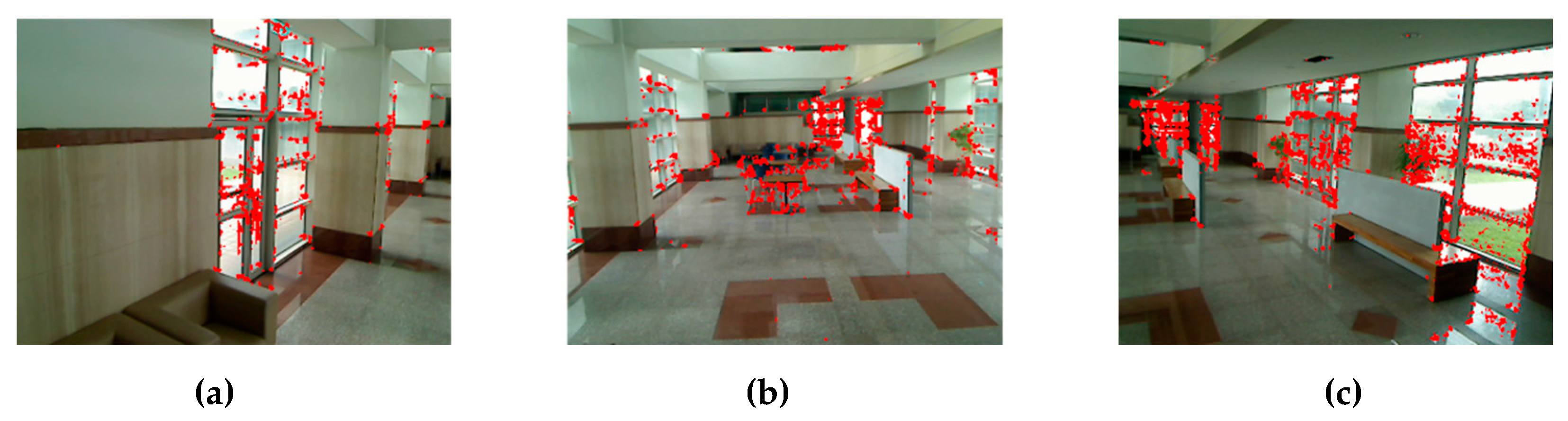
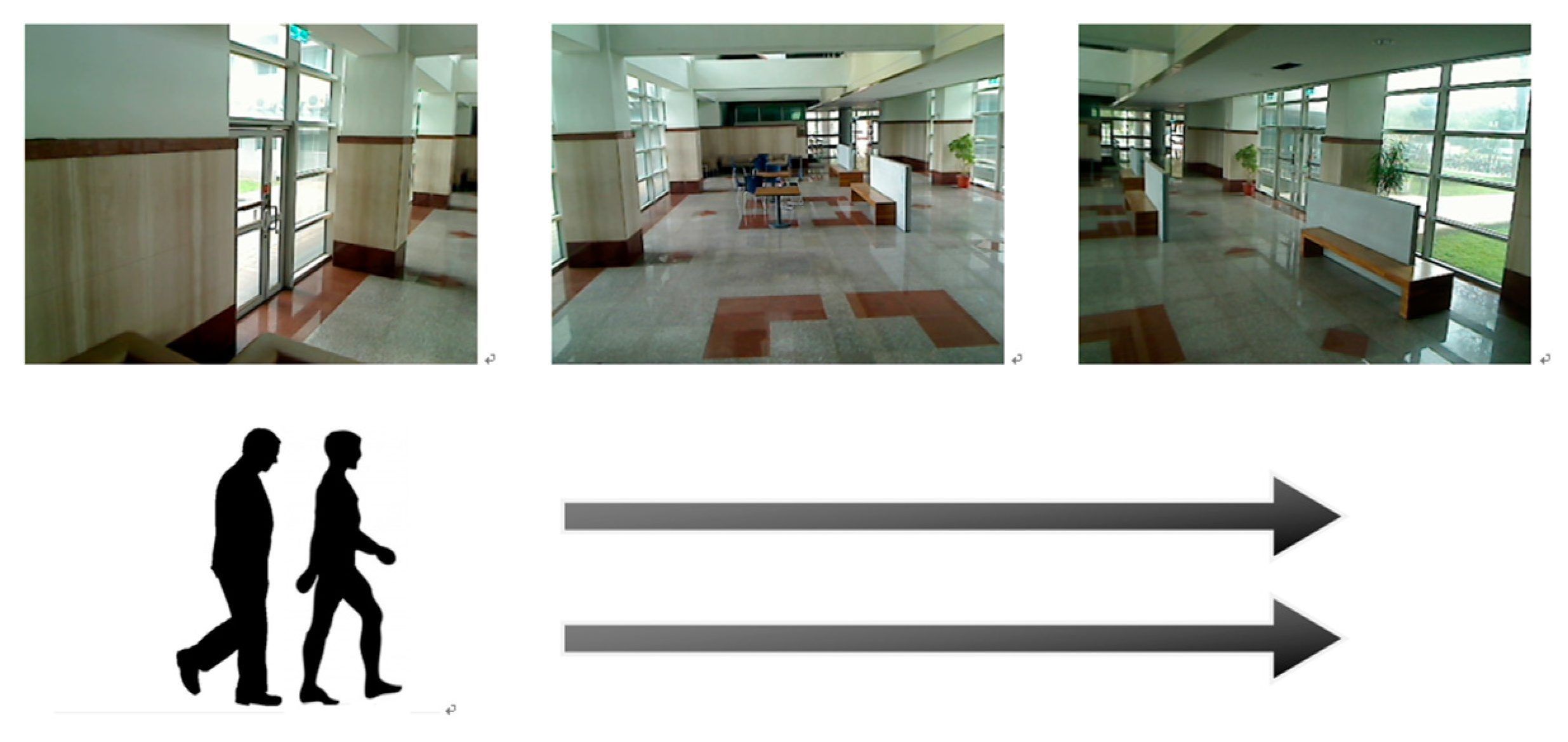
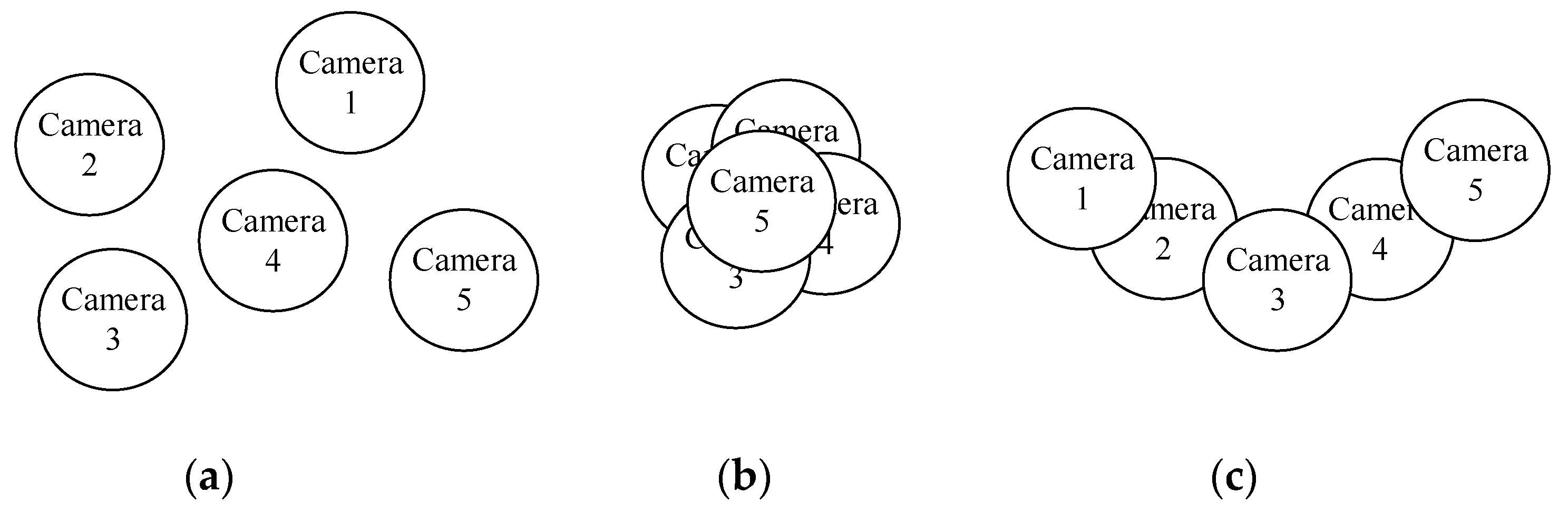
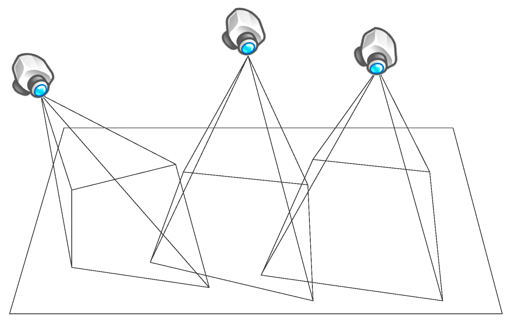
2.1. Cameras Network
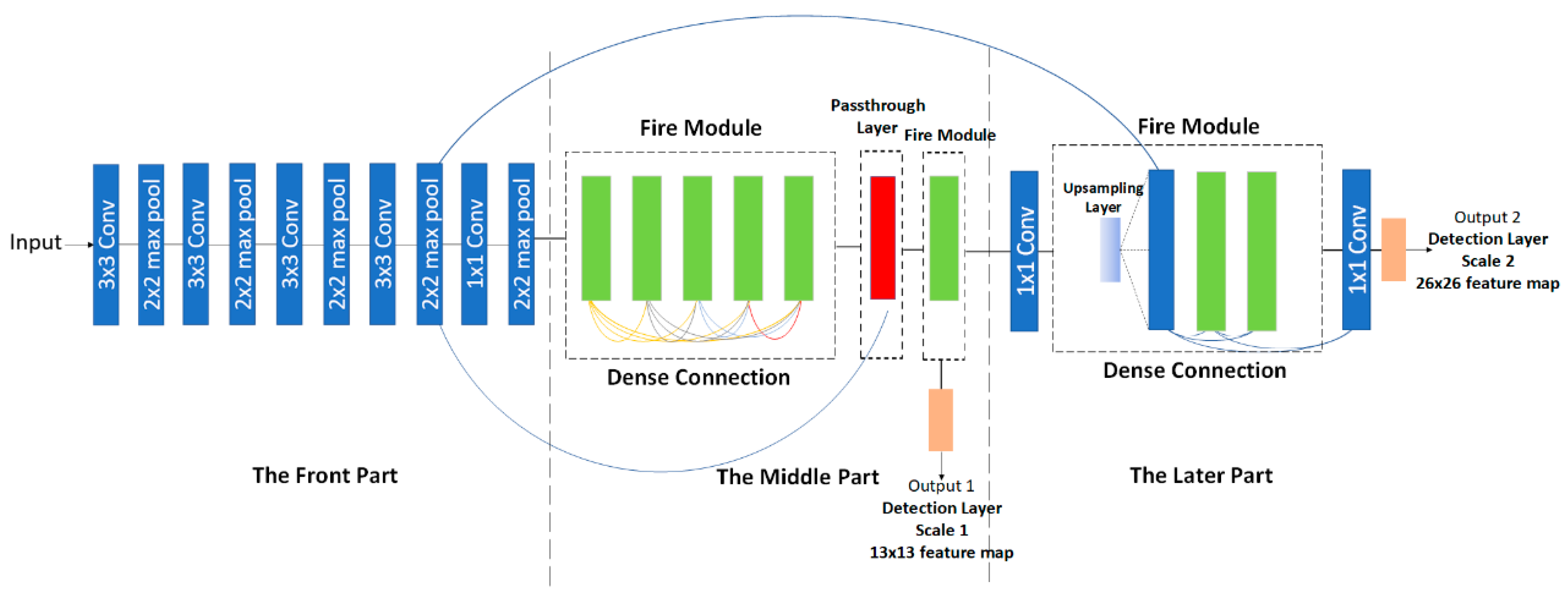
2.1.1. Moving Person Detection
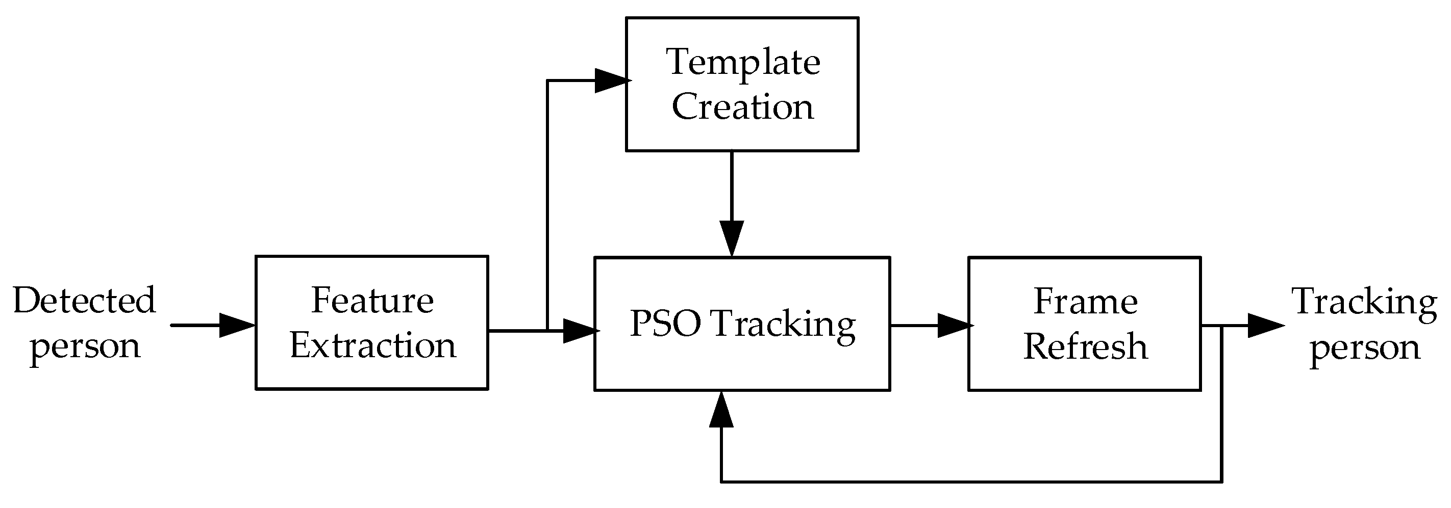
2.1.2. Person Tracking
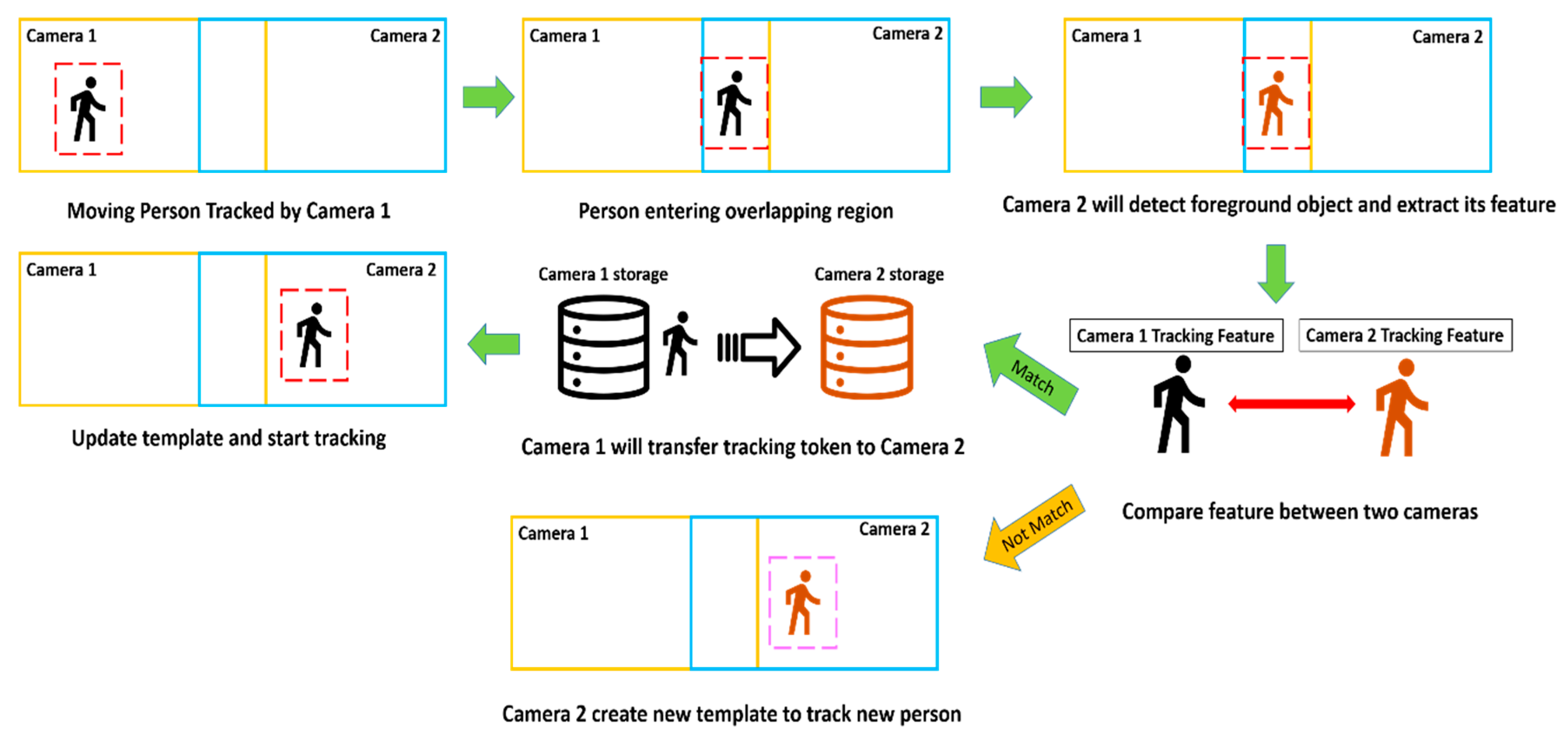
2.2. Cooperative Tracking
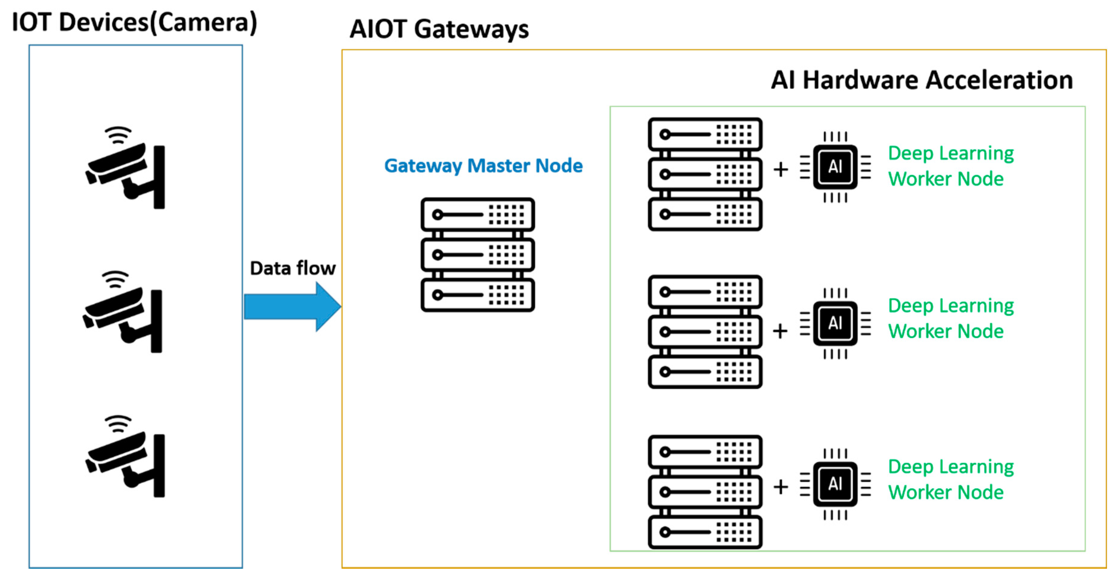
2.3. Gateway
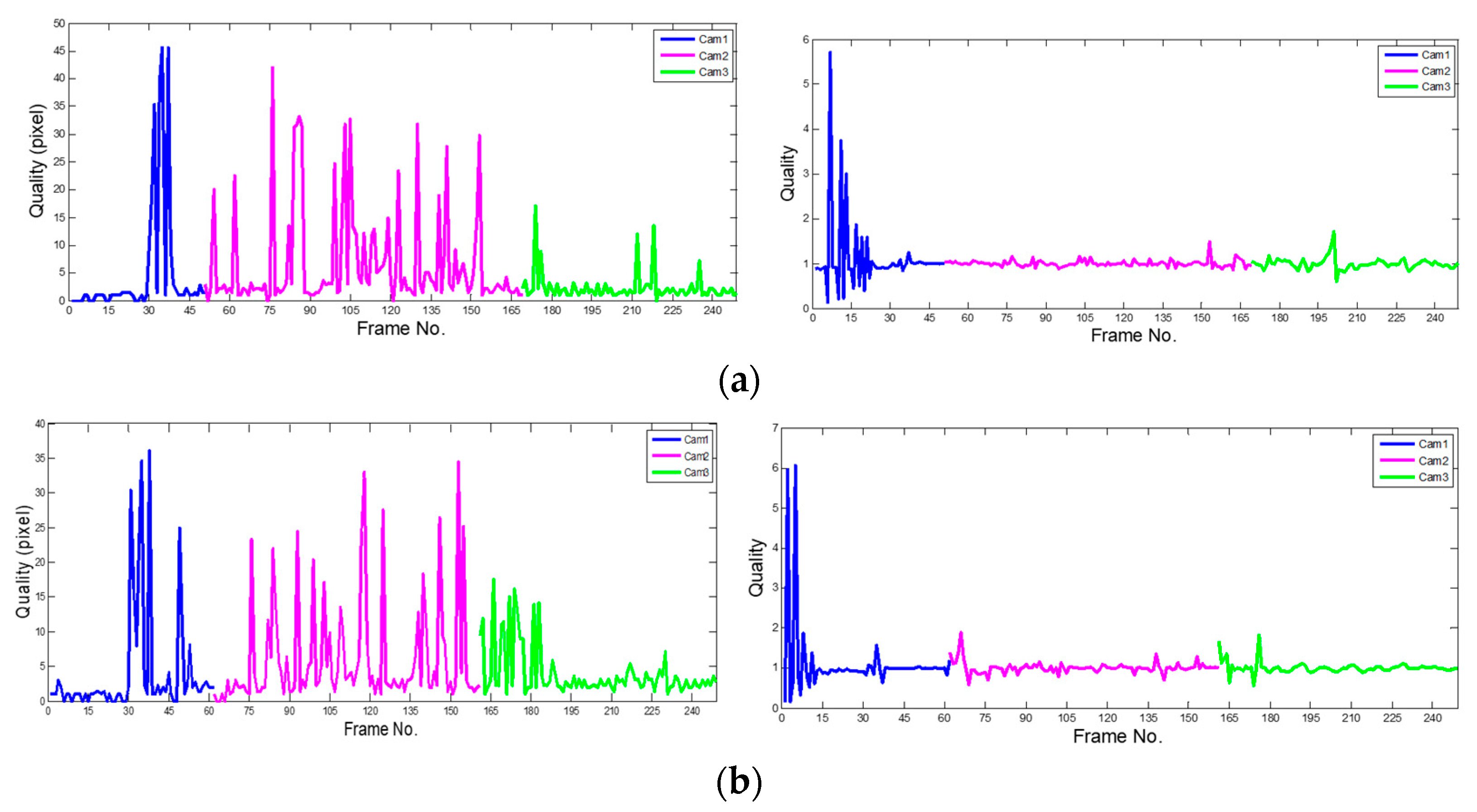
3. Results
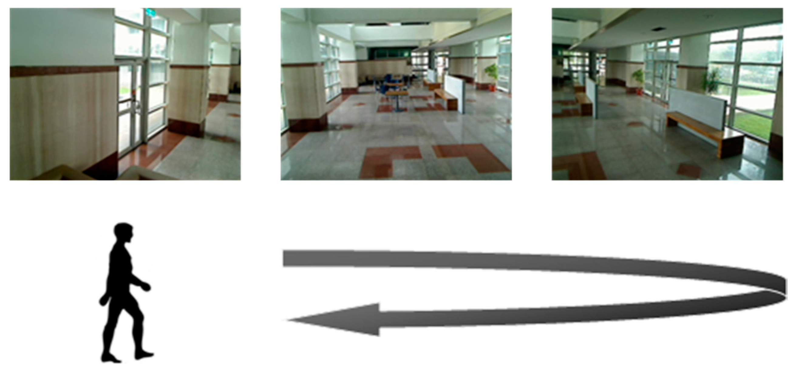
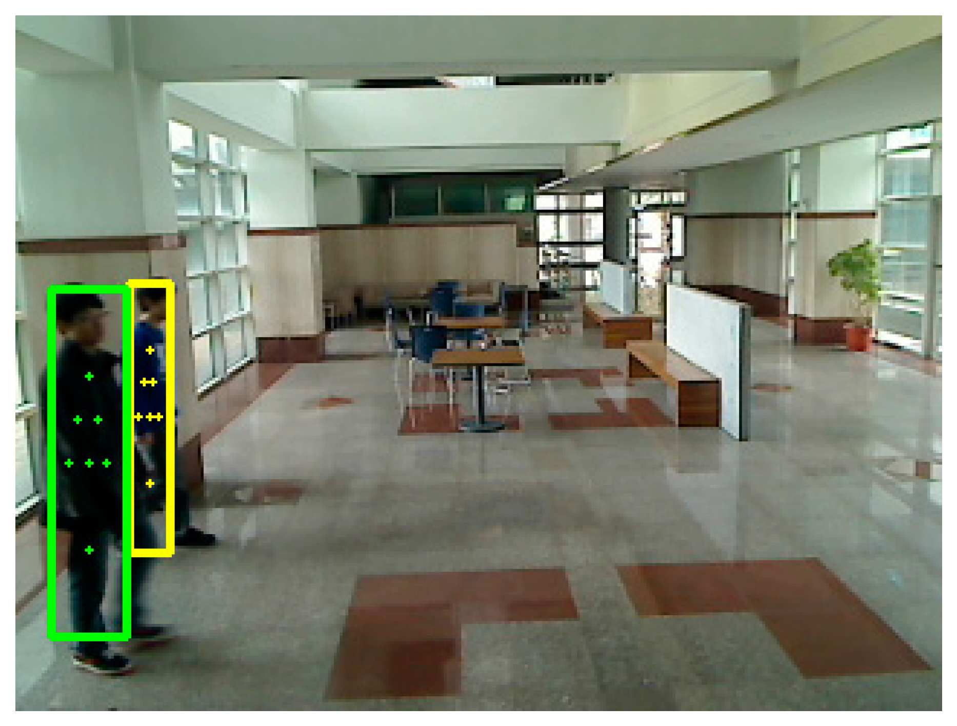
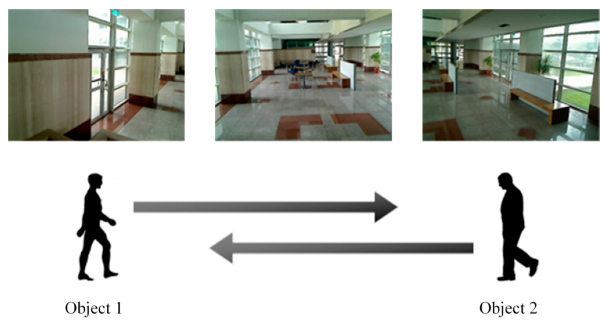
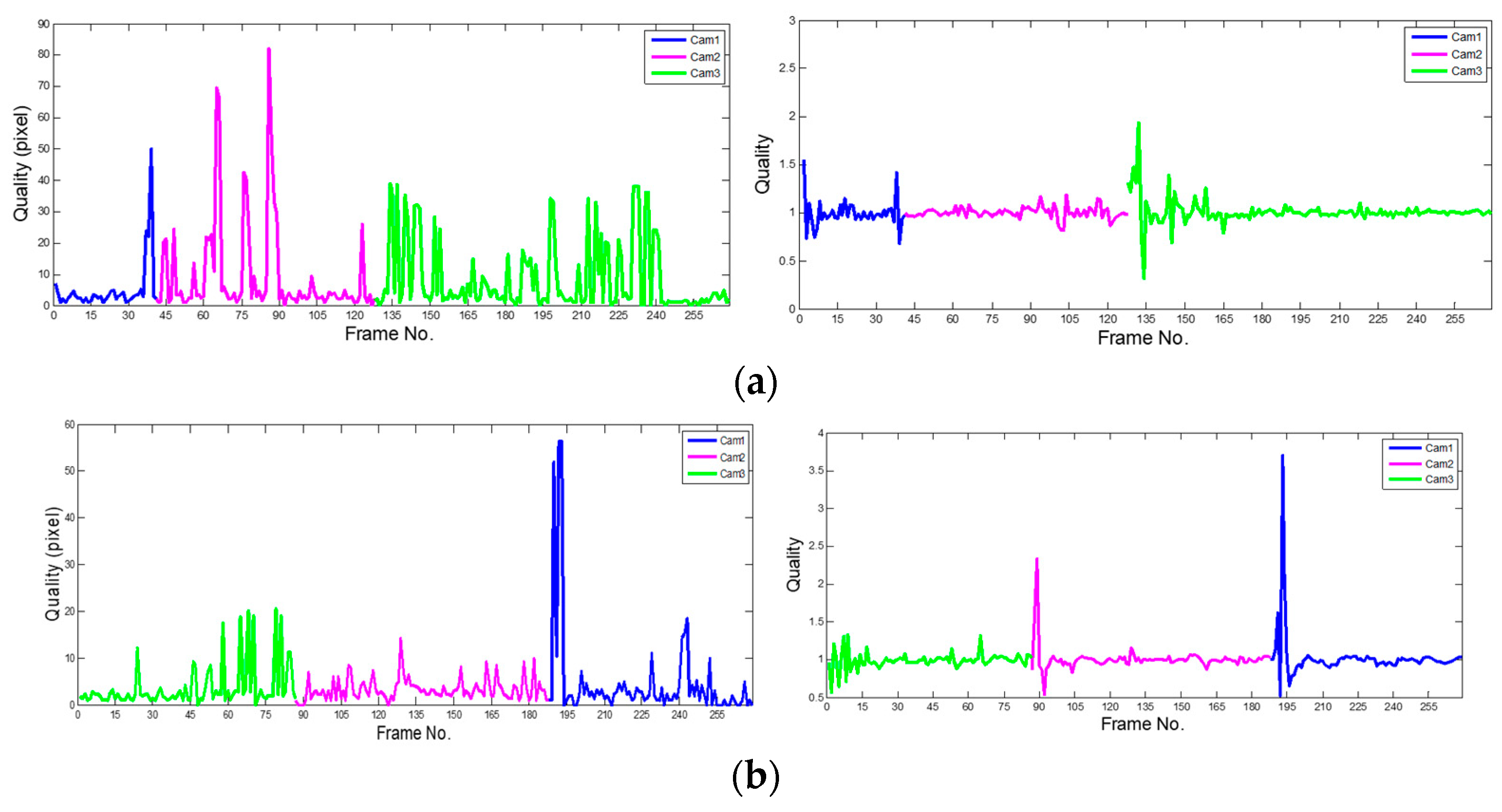
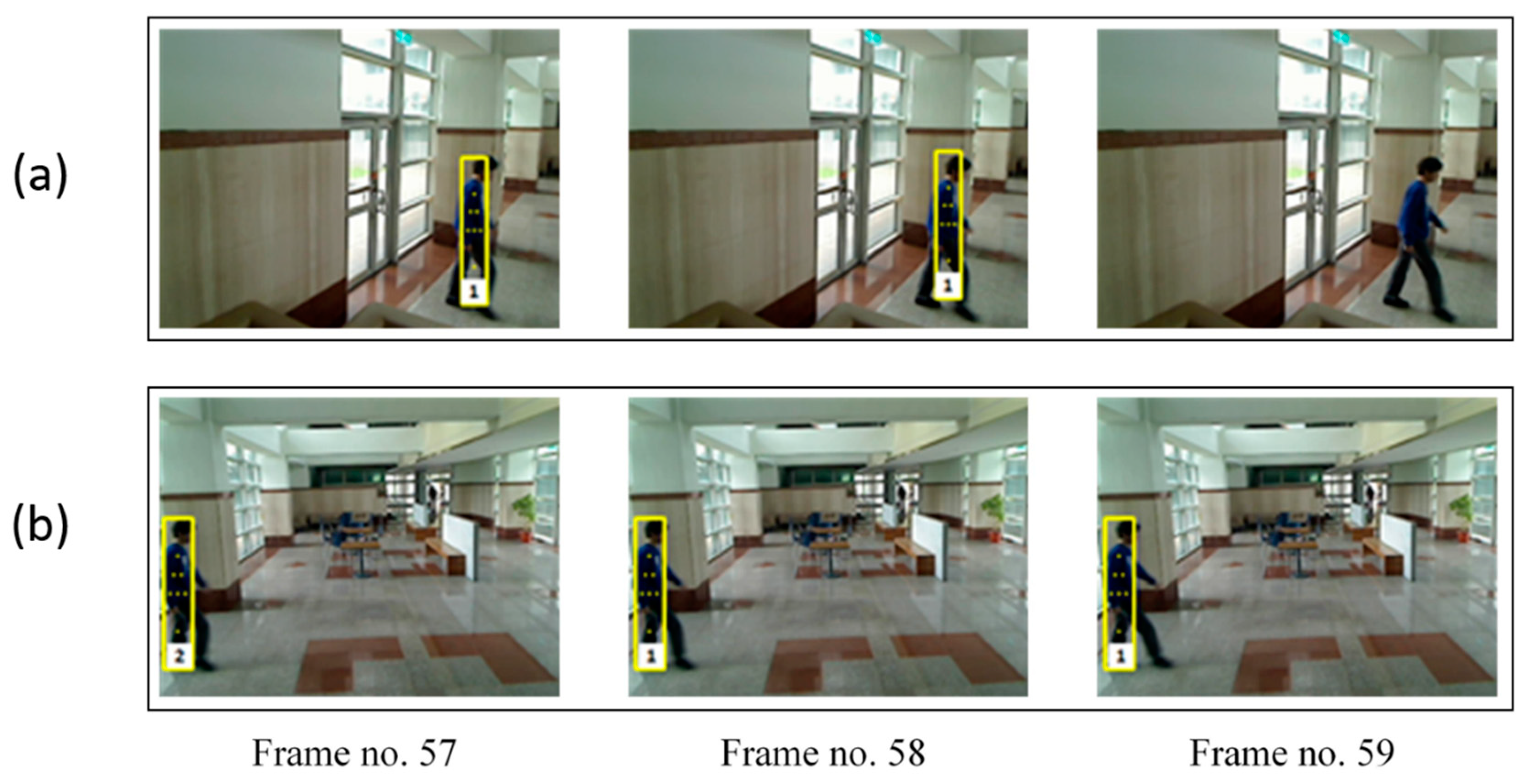
3.1. Tracking of One Person
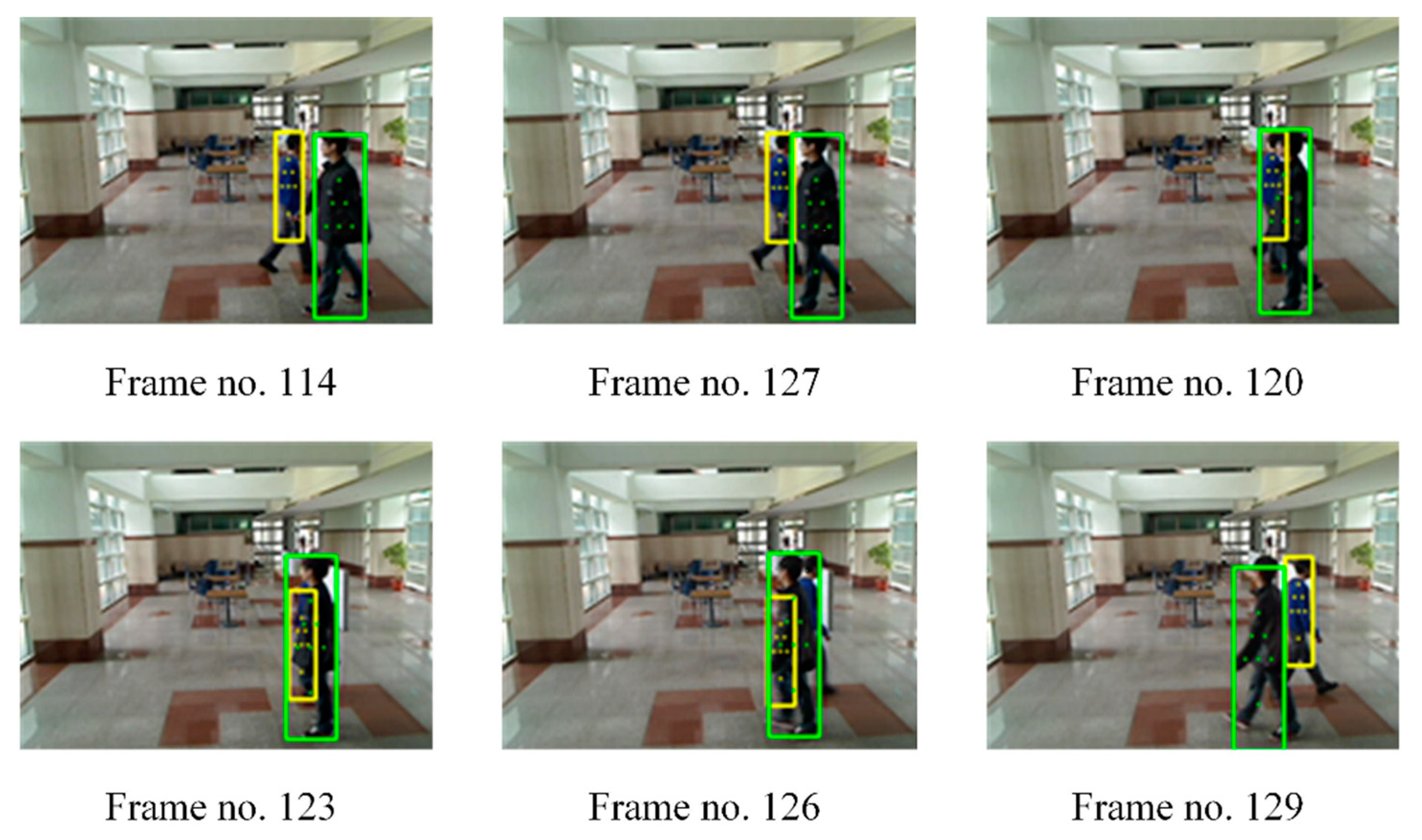
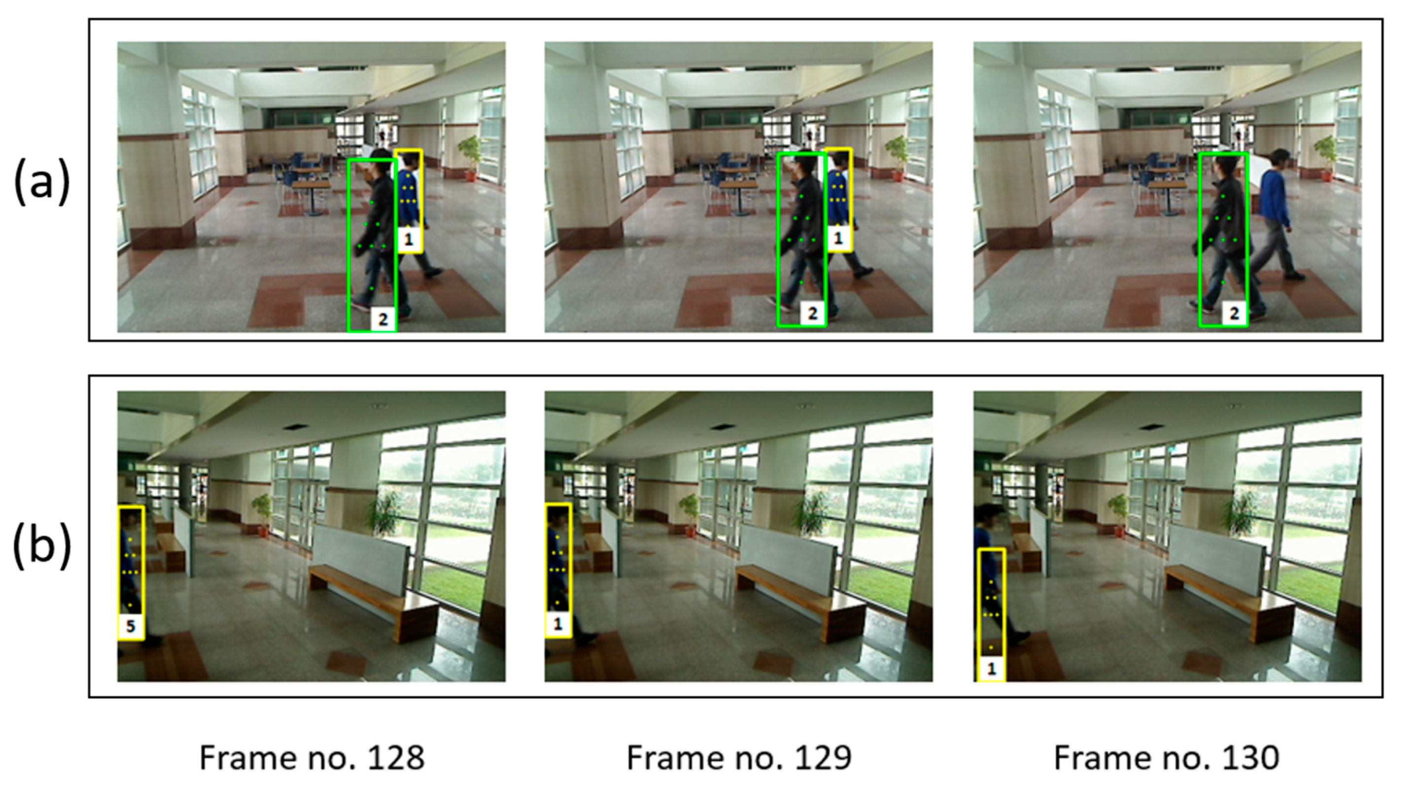
3.2. Tracking of Two People
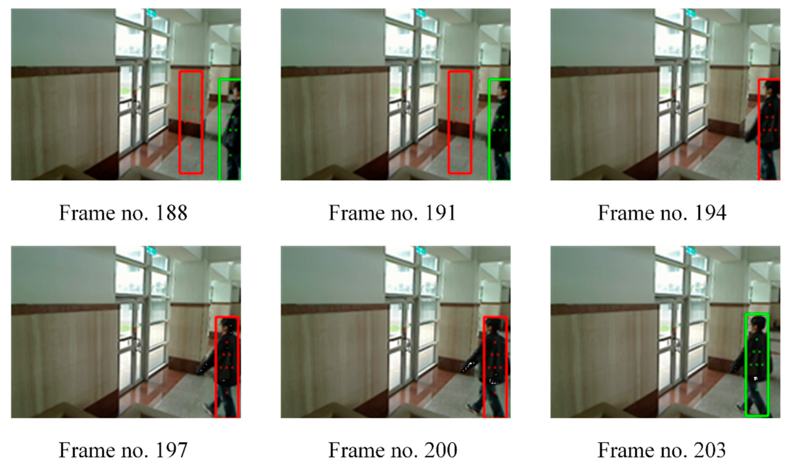
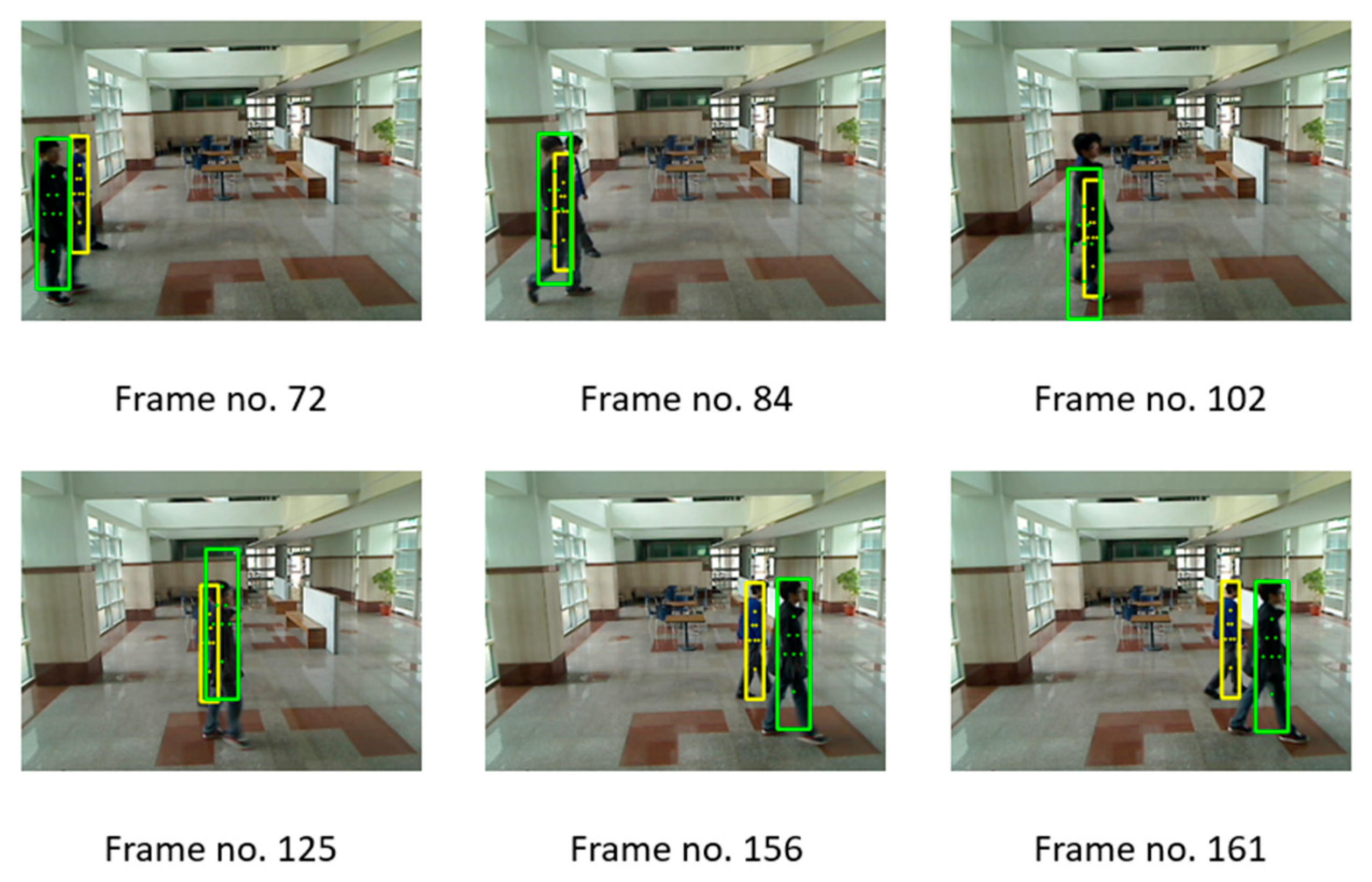
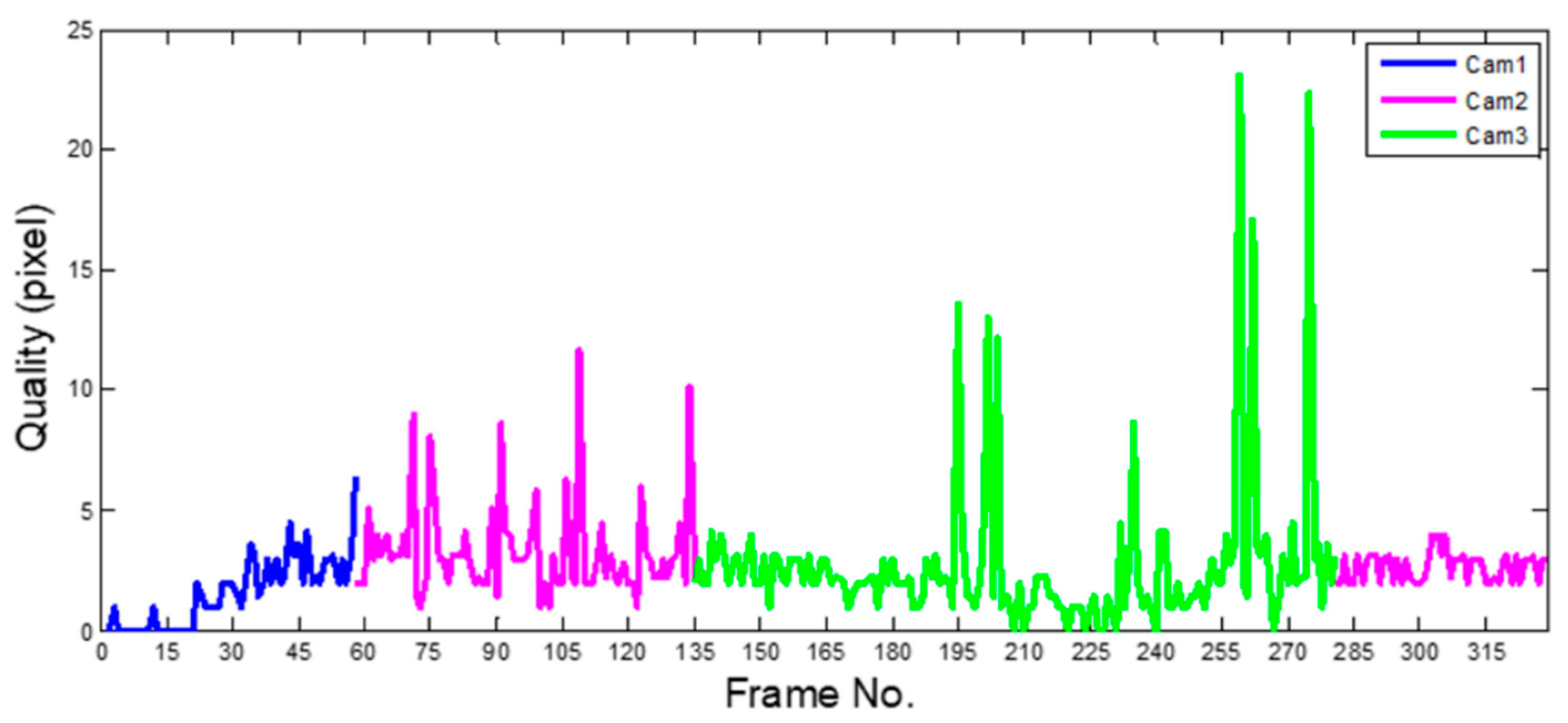
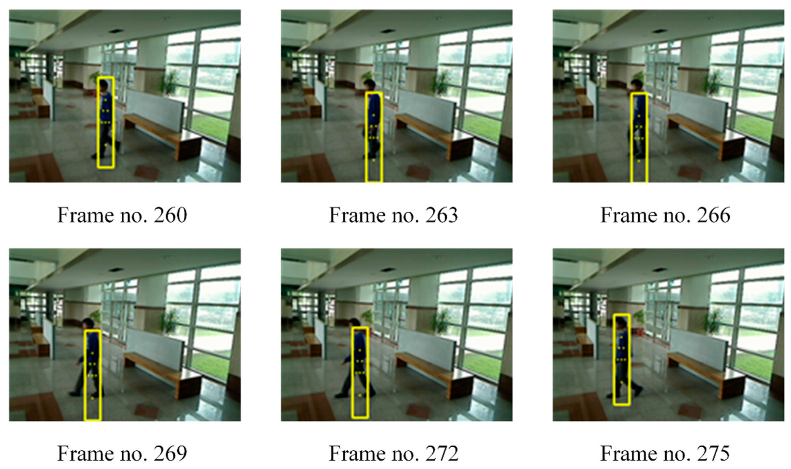
3.3. Tracking of Two Persons in Overlapped Scene
4. Conclusions
Author Contributions
Funding
Institutional Review Board Statement
Informed Consent Statement
Conflicts of Interest
References
- Wang, J.; Peng, K. A Multi-View Gait Recognition Method Using Deep Convolutional Neural Network and Channel Attention Mechanism. Comput. Modeling Eng. Sci. 2020, 125, 345–363. [Google Scholar] [CrossRef]
- Ding, L.; Wang, Y.; Laganière, R.; Huang, D.; Luo, X.; Zhang, H. A robust and fast multispectral pedestrian detection deep network. Knowl. Based Syst. 2021, 227, 106990. [Google Scholar] [CrossRef]
- Huang, Q.; Hao, K. Development of CNN-based visual recognition air conditioner for smart buildings. J. Inf. Technol. Constr. 2020, 25, 361–373. [Google Scholar] [CrossRef]
- Zhang, X.; Izquierdo, E. Real-Time Multi-Target Multi-Camera Tracking with Spatial-Temporal Information. In Proceedings of the 2019 IEEE Visual Communications and Image Processing (VCIP), Sydney, Australia, 1–4 December 2019; pp. 1–4. [Google Scholar]
- Benrazek, A.-E.; Farou, B.; Seridi, H.; Kouahla, Z.; Kurulay, M. Ascending hierarchical classification for camera clustering based on FoV overlaps for WMSN. IET Wirel. Sens. Syst. 2019, 9, 382–388. [Google Scholar] [CrossRef]
- Seok, H.; Lim, J. Rovo: Robust omnidirectional visual odometry for wide-baseline wide-fov camera systems. In Proceedings of the 2019 International Conference on Robotics and Automation (ICRA), Montreal, QC, Canada, 20–24 May 2019; pp. 6344–6350. [Google Scholar]
- Sonbhadra, S.K.; Agarwal, S.; Syafrullah, M.; Adiyarta, K. Person tracking with non-overlapping multiple cameras. In Proceedings of the 2020 7th International Conference on Electrical Engineering, Computer Sciences and Informatics (EECSI), Yogyakarta, Indonesia, 1–2 October 2020; pp. 137–143. [Google Scholar]
- Narayan, N.; Sankaran, N.; Setlur, S.; Govindaraju, V. Learning deep features for online person tracking using non-overlapping cameras: A survey. Image Vis. Comput. 2019, 89, 222–235. [Google Scholar] [CrossRef]
- Chapel, M.-N.; Bouwmans, T. Moving objects detection with a moving camera: A comprehensive review. Comput. Sci. Rev. 2020, 38, 100310. [Google Scholar] [CrossRef]
- Bisagno, N.; Xamin, A.; De Natale, F.; Conci, N.; Rinner, B. Dynamic Camera Reconfiguration with Reinforcement Learning and Stochastic Methods for Crowd Surveillance. Sensors 2020, 20, 4691. [Google Scholar] [CrossRef] [PubMed]
- He, L.; Liu, G.; Tian, G.; Zhang, J.; Ji, Z. Efficient Multi-View Multi-Target Tracking Using a Distributed Camera Network. IEEE Sens. J. 2020, 20, 2056–2063. [Google Scholar] [CrossRef]
- Cai, Z.; Hu, S.; Shi, Y.; Wang, Q.; Zhang, D. Multiple Human Tracking Based on Distributed Collaborative Cameras. Multimed. Tools Appl. 2017, 76, 1941–1957. [Google Scholar] [CrossRef]
- Huang, Q.; Rodriguez, K.; Whetstone, N.; Habel, S. Rapid Internet of Things (IoT) prototype for accurate people counting towards energy efficient buildings. J. Inf. Technol. Constr. 2019, 24, 1–13. [Google Scholar] [CrossRef] [Green Version]
- Jain, S.; Zhang, X.; Zhou, Y.; Ananthanarayanan, G.; Jiang, J.; Shu, Y.; Bahl, V.; Gonzalez, J. Spatula: Efficient cross-camera video analytics on large camera networks. In Proceedings of the ACM/IEEE Symposium on Edge Computing (SEC 2020), San Jose, CA, USA, 12–14 November 2020. [Google Scholar]
- Esterle, L.; Lewis, P.R.; Yao, X.; Rinner, B. Socio-Economic vision graph generation and handover in distributed smart camera networks. ACM Trans. Sens. Netw. (TOSN) 2014, 10, 1–24. [Google Scholar] [CrossRef]
- Tang, X.; Sun, X.; Wang, Z.; Yu, P.; Cao, N.; Xu, Y. Research on the Pedestrian Re-Identification Method Based on Local Features and Gait Energy Images. CMC-Comput. Mater. Contin. 2020, 64, 1185–1198. [Google Scholar] [CrossRef]
- Benito-Picazo, J.; Dominguez, E.; Palomo, E.J.; Lopez-Rubio, E.; Ortiz-de-Lazcano-Lobato, J.M. Motion detection with low cost hardware for PTZ cameras. Integr. Comput. Aided Eng. 2019, 26, 21–36. [Google Scholar] [CrossRef]
- Zhao, D.; Wang, H.; Yin, H.; Yu, Z.; Li, H. Person re-identification by integrating metric learning and support vector machine. Signal Process. 2020, 166, 107277. [Google Scholar] [CrossRef]
- Fang, W.; Wang, L.; Ren, P. Tinier-YOLO: A Real-Time Object Detection Method for Constrained Environments. IEEE Access 2020, 8, 1935–1944. [Google Scholar] [CrossRef]
- Eberhart; Shi, Y. Particle swarm optimization: Developments, applications and resources. In Proceedings of the 2001 Congress on Evolutionary Computation (IEEE Cat. No.01TH8546), Seoul, Korea, 27–30 May 2001; Volume 1, pp. 81–86. [Google Scholar]
- Yang, J.; Leskovec, J. Defining and evaluating network communities based on ground-truth. Knowl. Inf. Syst. 2015, 42, 181–213. [Google Scholar] [CrossRef] [Green Version]
- SanMiguel, J.C.; Cavallaro, A.; Martinez, J.M. Evaluation of on-line quality estimators for object tracking. In Proceedings of the 2010 IEEE International Conference on Image Processing, Hong Kong, China, 26–29 September 2010; pp. 825–828. [Google Scholar]


Publisher’s Note: MDPI stays neutral with regard to jurisdictional claims in published maps and institutional affiliations. |
© 2021 by the authors. Licensee MDPI, Basel, Switzerland. This article is an open access article distributed under the terms and conditions of the Creative Commons Attribution (CC BY) license (https://creativecommons.org/licenses/by/4.0/).
Share and Cite
Wu, Y.-C.; Chen, C.-H.; Chiu, Y.-T.; Chen, P.-W. Cooperative People Tracking by Distributed Cameras Network. Electronics 2021, 10, 1780. https://doi.org/10.3390/electronics10151780
Wu Y-C, Chen C-H, Chiu Y-T, Chen P-W. Cooperative People Tracking by Distributed Cameras Network. Electronics. 2021; 10(15):1780. https://doi.org/10.3390/electronics10151780
Chicago/Turabian StyleWu, Yi-Chang, Ching-Han Chen, Yao-Te Chiu, and Pi-Wei Chen. 2021. "Cooperative People Tracking by Distributed Cameras Network" Electronics 10, no. 15: 1780. https://doi.org/10.3390/electronics10151780
APA StyleWu, Y.-C., Chen, C.-H., Chiu, Y.-T., & Chen, P.-W. (2021). Cooperative People Tracking by Distributed Cameras Network. Electronics, 10(15), 1780. https://doi.org/10.3390/electronics10151780