1. Introduction
Yousif et al. [
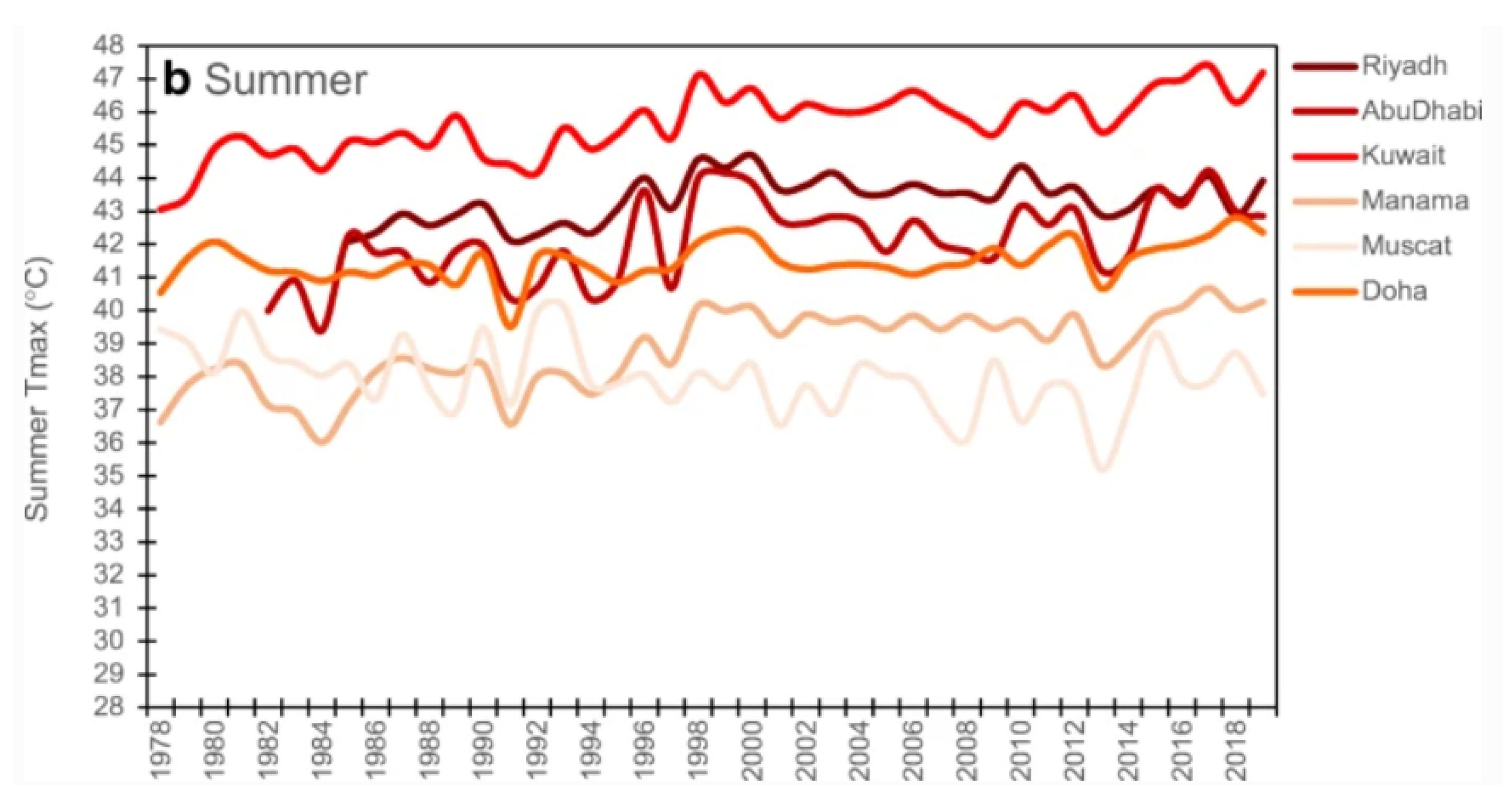
1] asserted that, due to the significant rise in temperatures, several cities in the GCC region, such as Jeddah, Dubai, Oman, and Doha, classify as having a desert climate. However, air humidity and temperature values are much higher in summer. The annual average relative temperature in the Gulf area is around 42
C. In GCC countries, the hot season lasts for five months, starting from the middle of May to the end of September, with an average daily high temperature above 44
C, as shown in
Figure 1. The hottest months of the year are July and August, with an average high of 47
C and a low of 42
C [
2,
3,
4,
5,
6]. The heat level in GCC countries impacts body function in outdoor activities. “Heat stress” indicates heat received in surplus that the human body cannot endure without suffering physiological weakness. Above a particular sill of heat stress, the body’s internal regulation mechanisms are no longer eligible for maintaining body temperature at a level required for regular activity. As a result, there is an increased hazard of limitations in physical functions, capabilities, discomfort, and ultimately also of injuries and heat-related diseases. Maintaining a core human body temperature of around 36
C is necessary to keep the body’s usual and continued function.
Heat stress endangers the safety of shoppers and workers and minimizes their activities [
7,
8]. That is why we must find a way to reduce this risk and encourage inhabitants to go out in the evening and wander in open areas. There are many solutions to help people to confront and adapt to this climate, especially outdoors [
9,
10]. Robotic technology has increased appreciably in the past few years. Robotics are involved in our lives and help humanity in many applications, most recently to fight the COVID-19 pandemic (Spry robot, Medicine delivery robot…) [
11,
12,
13,
14]. The University of Maryland created an object cooling system designed to conserve the user’s comfort and control, called RoCo [
15]. An RF signal controls the robot. The university developed several cooler robot prototypes with different specifications (Y1V1, Y2V2, Y3V1, Y3V3, and Y3V2) from the same department, but all without automatic tracking systems [
16]. In this fast-moving world, “human-following robots” are needed now to interact and coexist with us, as many applications and fields require a robot to follow a human.
Many researchers in the literature have studied specific person detection and tracking systems in outdoor applications. Most of the research efforts on target detection and tracking technique have been documented based on vision approaches. One essential task of vision-based object recognition is detecting and following the object in different environmental situations and conditions. The vision-based method is efficient. However, this technique is challenging for robust real-time objects, due to uncontrolled lighting conditions, motion targets in a cluttered environment, and moving cameras. This condition can cause loss of data in the captured image. The image data, such as color and quality, are essential for object recognition. The most technical application for object detection and tracking is in using a feature-based method. Most technical applications still focus on detecting motion, the shape of the object, and body skin color [
17]. Li et al. [
18] applied the color classification of skin regions for face detection. Ahmad et al. [
19] used a color-based method to identify the target object. They applied a specific algorithm to identify the object by using the color data of a dress. Lucas et al. [
20] created a system that uses laser technology to develop a robot that follows a human. The major disadvantage of the techniques stated above is that they cannot easily recognize the body from another body. On the other hand, a robot identifying a shopper by shape can also detect shapes not belonging to the same shopper.
The main problem with the idea of this project is that we cannot use face recognition technology to quickly track people in a market; it takes time to record different photos of the shopper and create a data set before using the robot, and sometimes, people may refuse to comply, considering it personal information.
In the present work, every shopper who wants to use an air-conditioned robot while shopping at the open market needs to wear a unique, yellow jacket. We use the jacket as a marker for target shopper detection. This system performs image processing for noising object subtraction, jacket identification, the position and distance between the air-conditioner robot and shopper determination, and then tracking a specific shopper. The main idea is to utilize the robot, which follows a human wherever they go.
Our study looks to fabricate a prototype robot that follows the identified person and produces a stream of air around them in open areas, especially in hot regions. With the evolution of computer vision technology and deep learning, the ways that researchers interact with technology are improving. Low-cost deep learning was researched recently, with the available technology, algorithms, and software development boosting their functions. The low cost of machine learning authorizes scientists to enjoy the advantage of this technique [
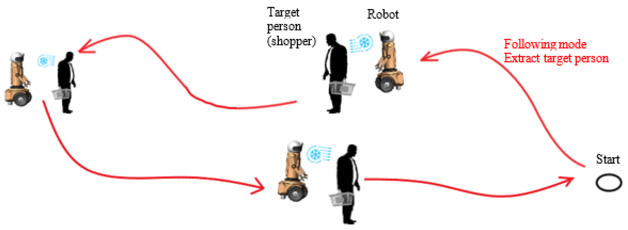
21]. In this work, we focus on developing a human-tracking intelligent robot to improve the high efficiency following system and provide a relaxing atmosphere for shoppers. To perform this task accurately, we need a mechanism to visualize the moving object and act accordingly. The robot air conditioner must be intelligent enough to follow a shopper in crowded areas and vivid environments, both indoors and outdoors, as illustrated in
Figure 2. The image processing carried out to fetch data on the surroundings, visually, is essential. This robot air conditioner is designed principally for two proposals:
Tracking shoppers quickly, accurately, and smoothly on a flat wooden floor, carpet, or concrete, keeping a safe distance from the target shopper of around one meter.
Cooling the weather and reducing the temperature around shoppers in open areas.
Various sensors can be used for human tracking. To target shoppers and bypass hurdles, we developed an ultrasonic-sensor array (Maxbotix LV EZ1). V2 cameras, which can deliver the three essential color components (red, green, and blue), are considerably used as image processing software for tracking and target detection. Most research studies have worked on these kinds of robots, but much work still needs to be done. For an air-conditioner robot to communicate and interact with the shopper, it should also follow that particular shopper. The V2 camera captures video in real time; based on the filter, we can determine the shopper’s coordinates. The robot stays on standby in different market areas and waits for the chosen color to be detected; then, the robot follows the shopper wearing the jacket. When the robot loses the shopper, it will issue an alarm, stop and turn off the air conditioner, as illustrated in
Figure 3.
The primary target of our work was to design and fabricate a prototype robot that tracks the shopper and follows them while moving. To make things simpler, a unique, handmade colored sticker was placed on the shopper for the robot to follow.
Typically, other robots are equipped with several sensors, such as LiDAR thermal imaging sensors, cameras, and radio frequency identification modules (RFID) for recognizing and locating the target. All the sensors and modules work in unison to detect and follow the target. Our robot can track and follow a moving object, which can be used for several applications and fields.
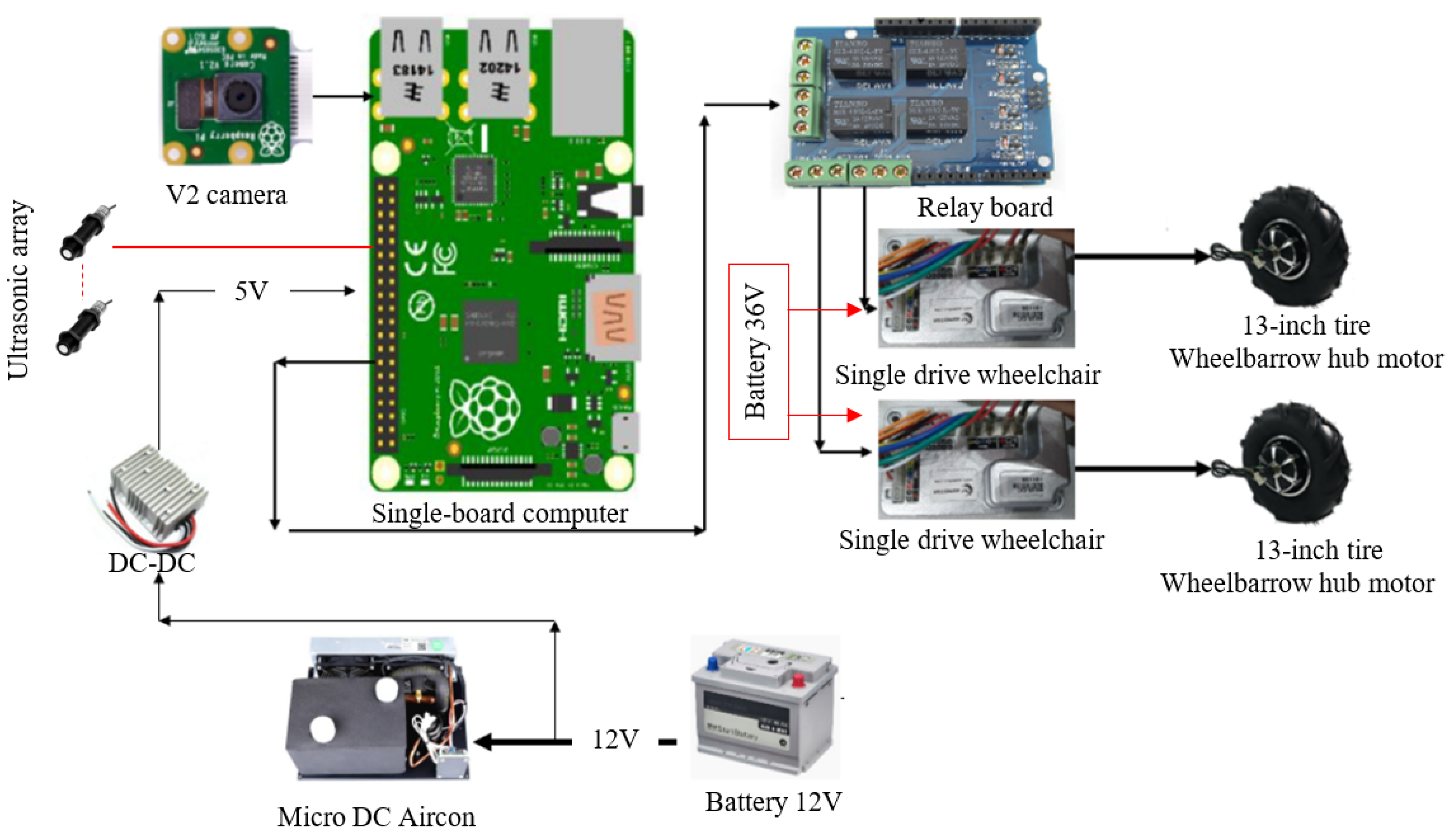
The schematic diagram of the several parts constituting this prototype, as illustrated in
Figure 4.
The prototype has several parts: the mechanical platform, an electronic circuit, unique color detection, and an intelligent tracking system. This manuscript is structured as follows:
Section 1 is the introduction.
Section 2 presents the development of the hardware setup to track a moving object based on computer vision.
Section 3 presents the outdoor airflow analysis. In
Section 4, we present and calculate the kinematics of the differential drive caster robot. Finally, we finalize with a prototype discussion and conclude future work.
2. Development of Hardware Setup to Track a Moving Object Based on Computer Vision
Recently, the research of tracking moving objects has grown considerably [
22,
23,
24]. Many of them use Raspberry Pi single-board computers for low-cost embedded systems. Many research studies use this computer for signal processing, image processing, and robotic applications. In this work, shopper detection based on the V2 camera is achieved by the color detection and tracking function of OpenCV. OpenCV provides a human-tracking algorithm solution. However, specified color detection and following are easy. Therefore, the color following the procedure provided by OpenCV was adopted in this application. Furthermore, OpenCV processes images by pixels, so the status of the selected colors is also presented by pixels. The V2 camera is utilized to obtain real-time video. The image is processed, using pattern recognition and an image processing method to detect and recognize patterns, as shown in the following research studies [
25,
26,
27,
28]. The image processing method uses, for the detection of color codes, multiple types of filters. In this research, the robot prototype constitutes several hardware components for testing and validation in the actual field. The image processing algorithm for specified color detection was developed under a Python environment for reducing noise in the background of the moving object (the shopper). The image processing method aimed to detect the color worn by the shopper. For our research, after setting the image processing method, it was implemented in the robot model, and it was controlled using artificial intelligence. Implementing a human interactive robot seems simple, but presents such problems as detecting a particular moving object in a crowded area.
Several research studies confirmed that the number of colors in a lively environment and a low-noise crowded area is not combined in real-time video frame analytics [
29,
30,
31,
32,
33]. So, we designed an algorithm to overcome this problem. The final design, with high efficiency, can synchronize with the mechanical platform of the robot. The implementation of the algorithm is as follows.
We used the OpenCV package to change the color space from the RGB model to the HSV model. The HSV was selected for its ability to accommodate variable lighting situations (sunlit or dark areas).
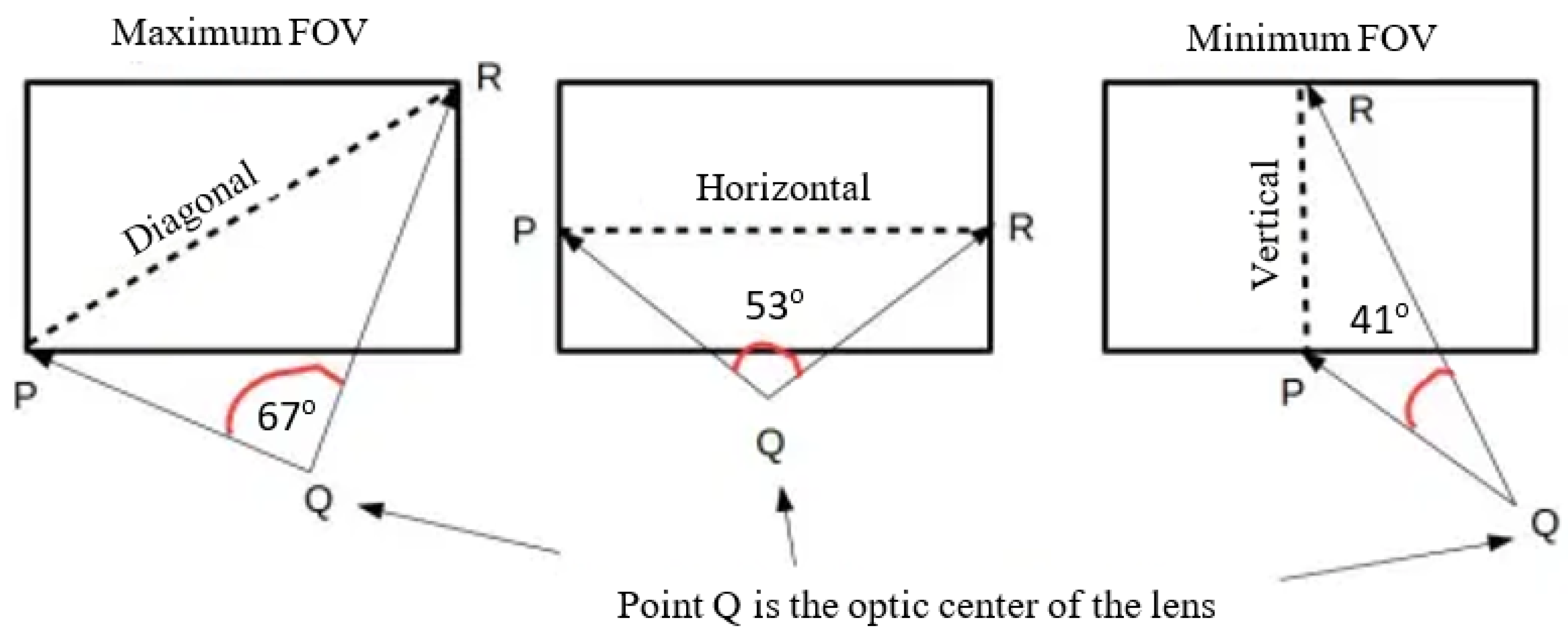
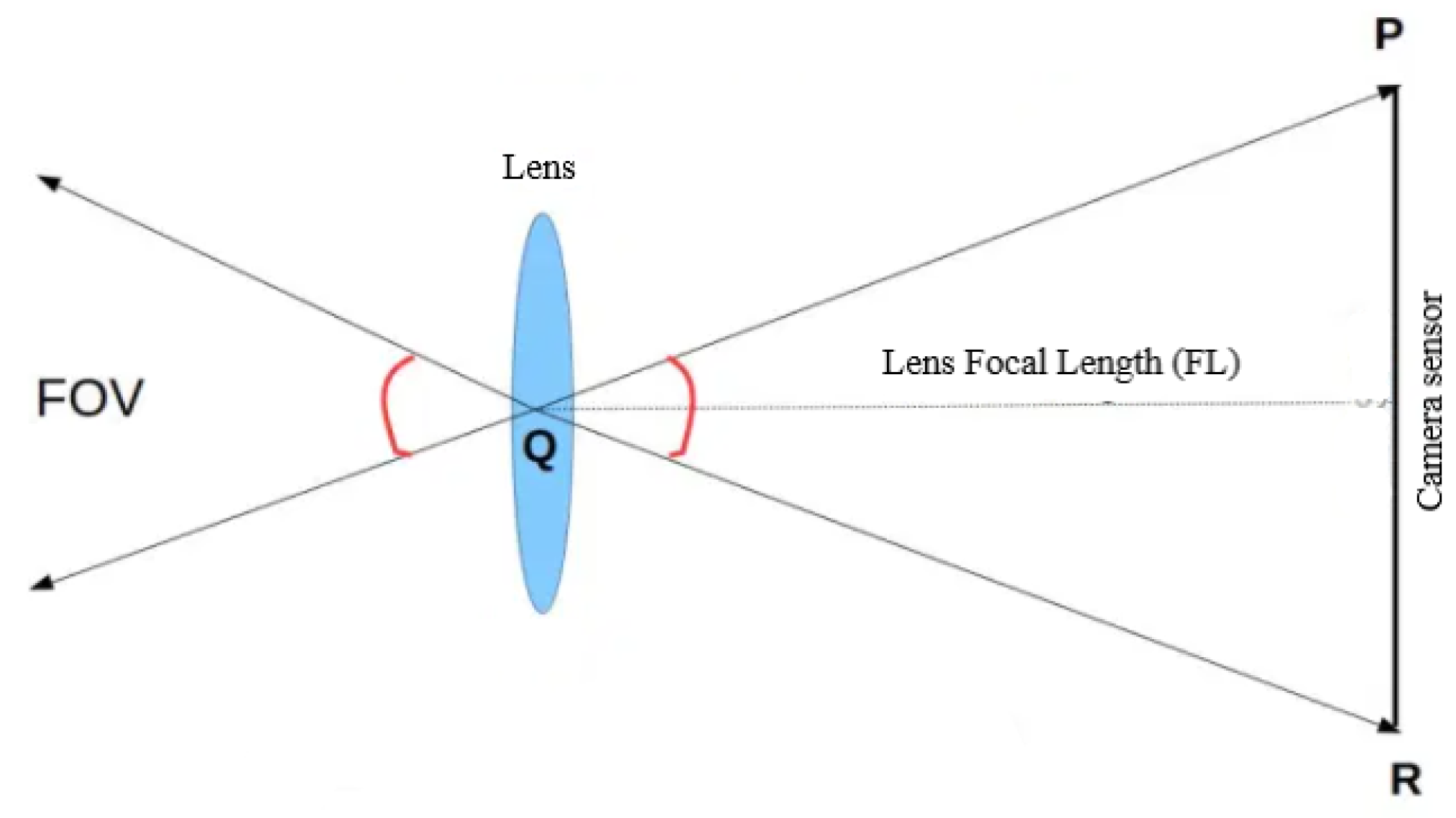
2.1. V2 Camera FIELD of View
The video camera comes with a small lens with a field of view of about 67
diagonal (41
vertical and 53
horizontal). The field of view (FOV) is the angle subtended by the camera sensor at the optical center of the lens. To calculate the field of view value, we use the trigonometry Equation (
1), and all we need to do is apply the procedure shown in
Figure 5. It is essential to understand that FOV follows the focal length of the lens (FL) and depends on the spatial range of the video camera sensor [
34,
35,
36]. In
Figure 6, the FOV is angle Q in the right triangle PQR. If we extend the lines that form the FOV angle inside the camera into the real world, it is easy to determine the angular limits of our video camera.
We can measure the FOV of the lens on our camera, where the V2 camera specification is FL = 3.04 mm.
The horizontal length of the Pi camera sensor = 4.6 mm.
According to Equation (
2), the horizontal FOV = 74.17
.
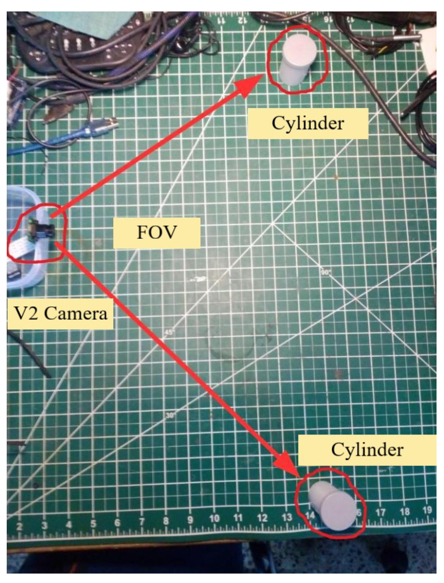
We fixed the camera sensor on the workshop table and used objects to measure the FOV of the camera, physically. In
Figure 7, we see the configuration from the top view. We measured the perpendicular distance of the camera to the line of the cylinder and then measured the distance between the cylinders. We were able to calculate the actual FOV value [
37].
Figure 7 shows an image taken by the camera, showing both cylinders, which are just within the horizontal frame.
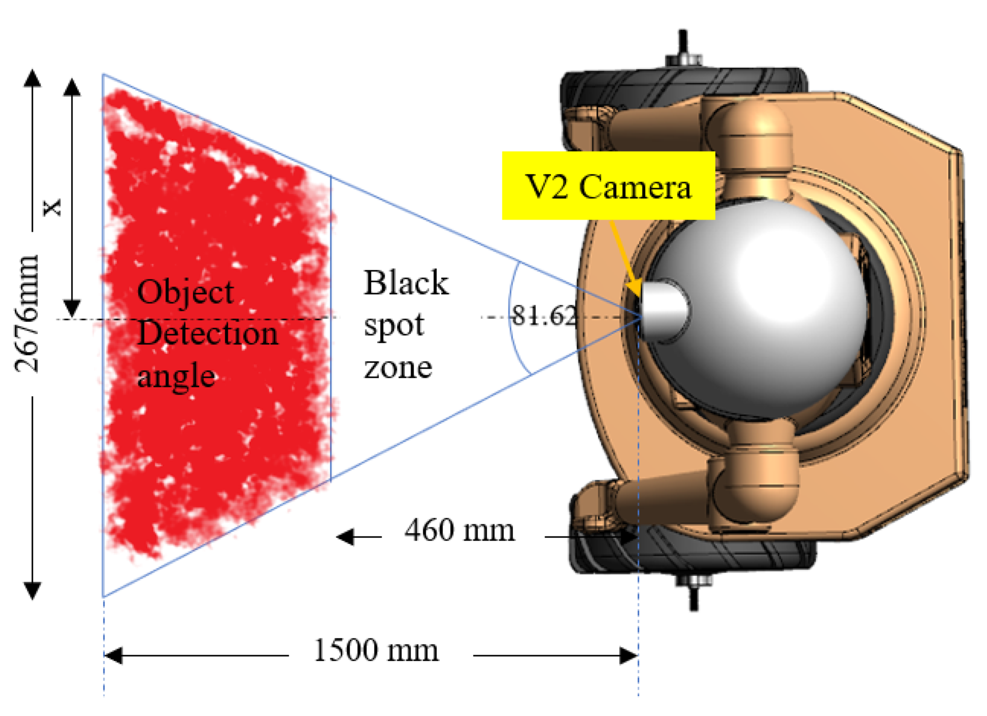
The object detection zone determined by the camera, which has a window view on the red zone, is shown in
Figure 8. The robot has a black spot area in front equal to 460 mm and has an angle of 83.49
in the horizontal field of view. The moving object coordinates detection by remaining in the range of the detection area with the geometry method.According to Pythagoras formula Equation (
4), the entire front view of the robot is approximately 2676 mm × 1500 mm. This geometric calculation gives us the maximum extent to which a robot can determine colors and track a person within the market. If the person is inside the blank spot area, the robot will stop moving, as well as if the person is outside the monitoring field.
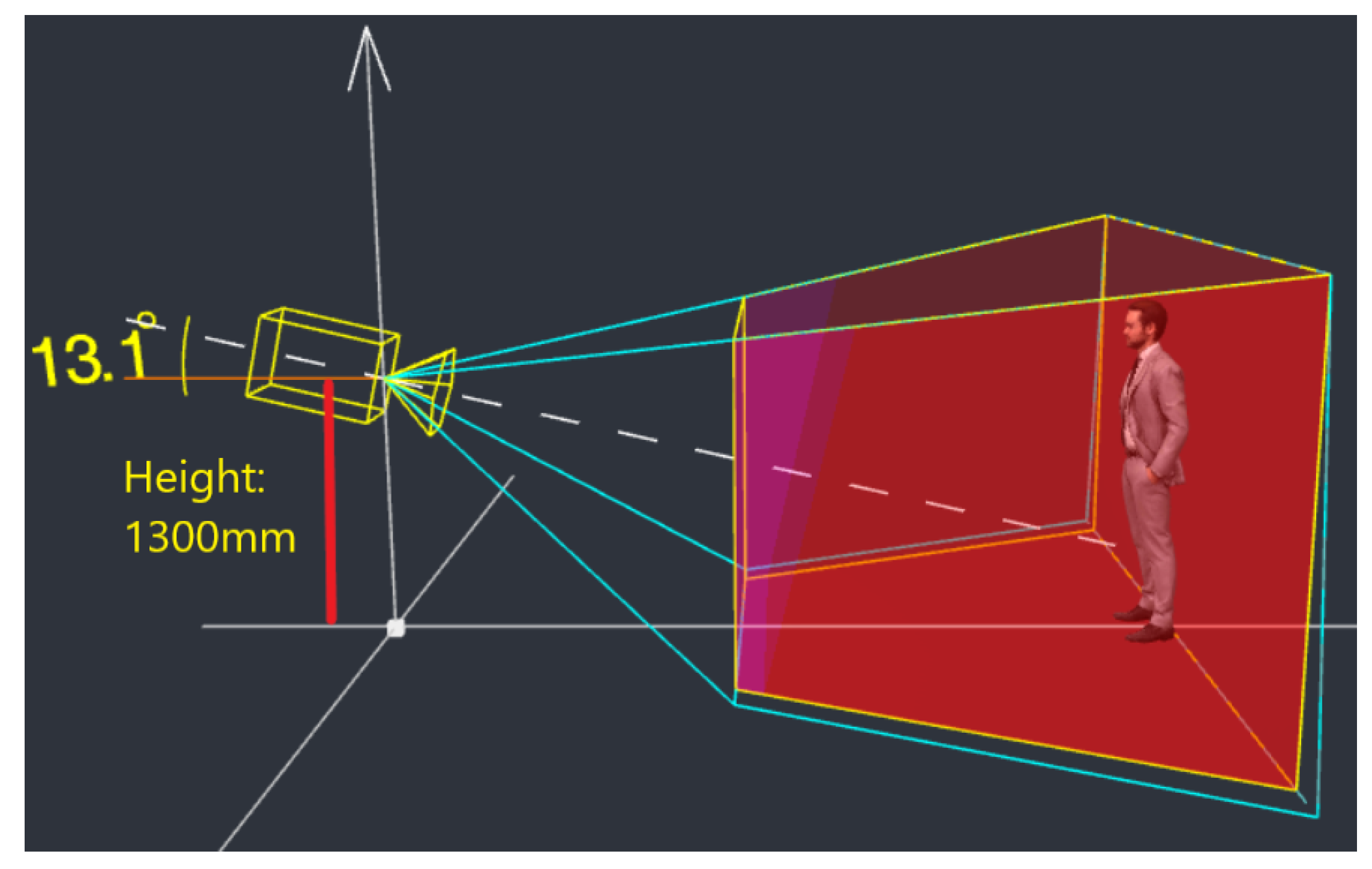
The blind spot of the robot camera is the area under the camera where the camera cannot view the ground and should be included this limitation during the prototype development. The video camera is positioned at the robot’s head at a height of more than a meter and thirty centimeters. This camera is mounted with an angle inclination of around
. This camera position can follow the shopper with high efficiency and accuracy, as shown in
Figure 9.
2.2. Design a Custom Tag (Color Label)
The V2 camera sensor captures video in real time in standard color format (RGB). To segment the moving object colors more absolutely and efficiently, we convert from the RGB format to the HSV color model [
38,
39,
40]. For segmentation, the target color to be attached to the back of the target shopper, in the HSV color space, is chosen according to the wide range of color space and what can be easily distinguished. Where H—hue (color);
S—saturation (color intensity);
V—value (luminosity).
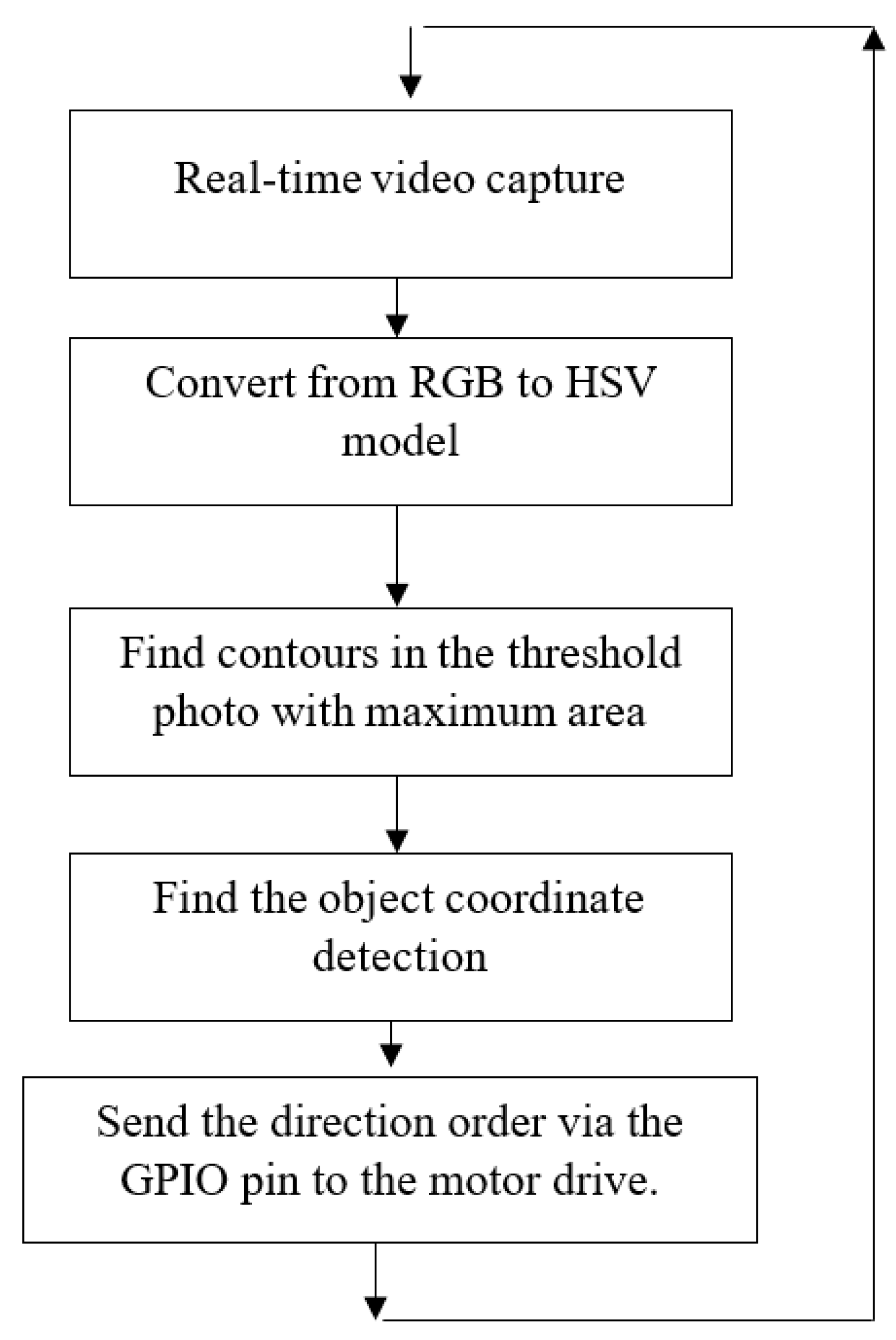
After transformation, the HSV model image is divided into three separate channels and is processed. Each channel is processed separately, and the target color to be attached to the back of the moving object is segmented, filtering out the environmental colors. The algorithm for the color transformation from the standard color model to the HSV format, as shown in
Figure 10, consists of the following tasks:
Real-time video capture.
Separating the components of HSV.
Thresholding.
Totaling the thresholded HSV color.
Moving object detection.
Calculating the coordinates of the moving object.
Sending the direction order via the GPIO pin to the motor drive.
Suppose a computer vision (CV)-related application deals with tracking a specific target shopper. In that case, it is required to identify the range of HSV (hue, saturation, and value) values of the target shopper. This range needs to be specified as part of the coding to reveal that shopper. If the correct content is not selected, the CV algorithm may pick up noise besides the actual shopper, leading to false detection and tracking [
41,
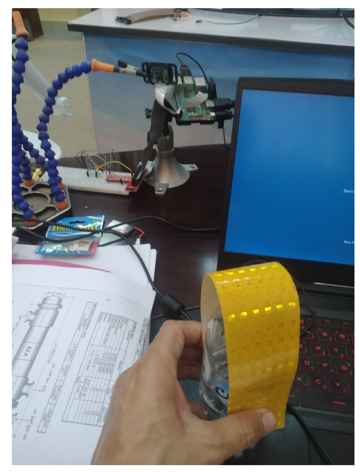
42]. To identify the yellow reflective sticker alone, without any other objects or noise, it is indispensable to specify an accurate range of corresponding HSV numbers; this presents a big challenge for this application, allowing to follow moving shoppers and ignoring other colors of the HSV near the selected code color. Since the sticker has a yellow reflective color, we chose a low number after selecting the HSV (hue, saturation, value) values for the pale yellow sticker [
43,
44]. We conducted many iterations to determine the unique value required and reduce the image noise from the background and the crowded environment around the followed shopper, as illustrated in
Figure 11.
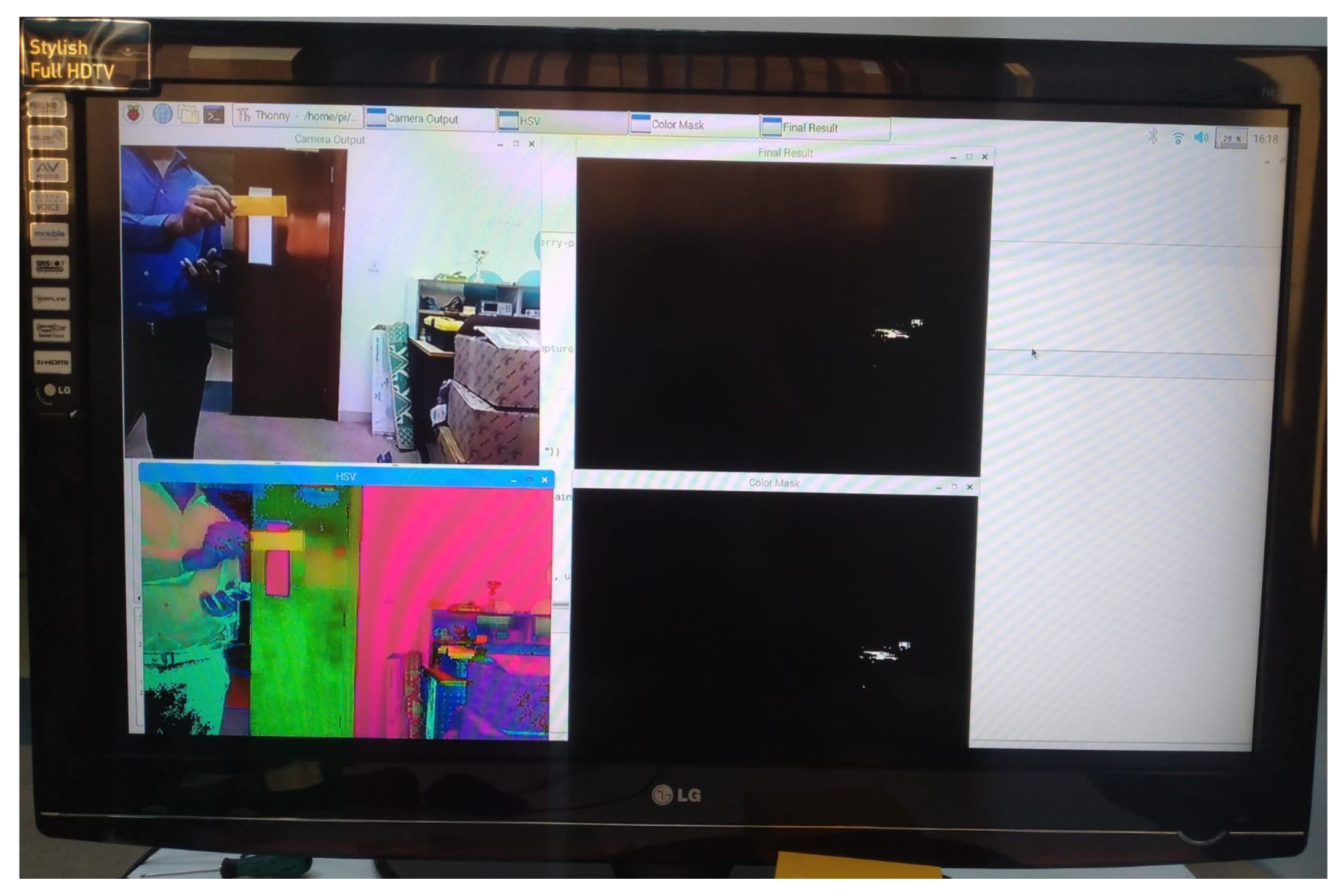
The experiment comprises placing the sticker on the moving object approximately a half-meter in front of the camera. We write the code on Raspberry Pi to determine the exact HSV value that enables us to see and detect the bright yellow color with the camera. When the software runs automatically, we see four windows: RGB representation, HSV representation, the color mask, and finally, the entire frame minus all portions that do not have an HSV level hue value decided as illustrated in
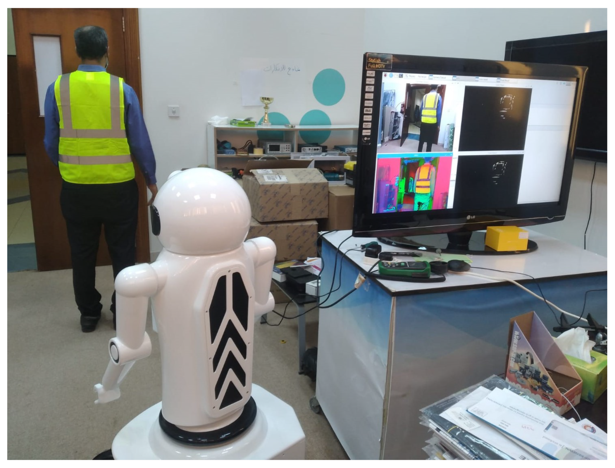
Figure 12. In the first step, we use a yellow reflective sticker attached to the back of the shopper. After many experiments and iterations, we concluded, after transferring the video to an HSV format, that we cannot detect only the bright yellow sticker with their minor noise level, which causes low-accuracy tracking. The upgrade idea is to use a safety jacket because its size and HSV efficiency are very high and the effect of noise is very low as shown in
Figure 13. This research pays attention to the noise and illumination effect. The specified filter uses the HSV method to detect the yellow color of the safety jacket.
Different experiments are conducted along with performance of the algorithm. Each iteration performed took approximately 2 min to 5 min. Based on the results obtained from these tests and experiments, we made the necessary changes in the processing algorithm. The safety jacket gives good results and reduces the noise in the background of the shopper. The image processing presents how an algorithm is applied to detect the moving objects and their frame from the image algorithms, such as color detection and classification. Image analysis and understanding are the last components of computer vision. This allows making decisions based on the program applied in the prototype after the analysis.
2.3. Color Filtering Test
To obtain the maximum of the color filter process capabilities, we tested the performance of color filtering. The test focused on detecting the yellow color from the environment after using the illumination filter. The testing was done by calibrating the threshold of the color filtering component in the image color space to the HSV color distribution method. This test takes care of the influence of the intensity of light provided when testing color filtering. The range of hue values is represented between 10, the minimum value, and 255, the maximum value. The variable of threshold hue filtering has a range of deals from 10 to 255. The testing process is determined by changing the hue filtering threshold value on the trackbar, as shown in
Table 1.
lower_color = np.array ([HUE_VAL-10,100,100])
upper_color = np.array ([HUE_VAL+10, 255, 255])
hsv = cv2.cvtColor (image, cv2.COLOR_BGR2HSV)
Then, depending on the color tracked, there should be a lower and a higher range of the other colors. The code detects and selects only the color in this range. We conduct image masking, which returns a binary matrix by considering the range of the color.
image_mask = cv2.inRange (HSV, low, high)
If we conduct a logical mask with the original images, we can see the image with the defined color.
Output = cv2.bitwise_and (frame, frame, mask = image_mask)
2.4. Testing Moving Object Coordinate Detection
The test of the moving object coordinates is necessary for checking the ability of the air-conditioner robot in detecting the shopper in the market based on the coordinates of the camera filter. The coordinates are fixed from the center point of the moving object’s filtered area. The test data and information corresponding to the coordinate detection frame are shown in
Table 2. The resolution used is 640 × 480 pixels, so the maximum value of the
x-axis is 640, and the maximum value of the
y-axis is 480.
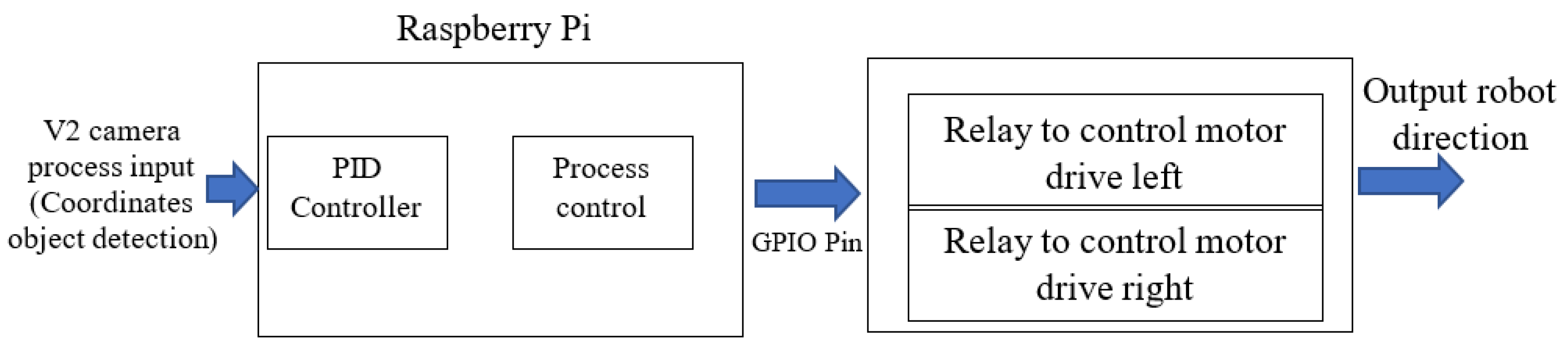
2.5. Implement a PID Controller
The 13
tractor tire wheelbarrow hub motor can be implemented, using a Raspberry Pi, motor drive, and V2 camera. Now, a PID-based hub motor controller program is developed; to do so, we connect the input, output, and feedback units to the configured GPIO pins [
45]. The wheelchair motor drives the hub motor depending on the object coordinate detection. The moving object coordinate detection is used to control the hub motor direction. The coordinate signal is fed to the computer (PI 3) to reiterate the system’s process in a balanced state [
46]. The PID-based hub motor controller is designed to control the constant speed hub motor, as shown in
Figure 14.
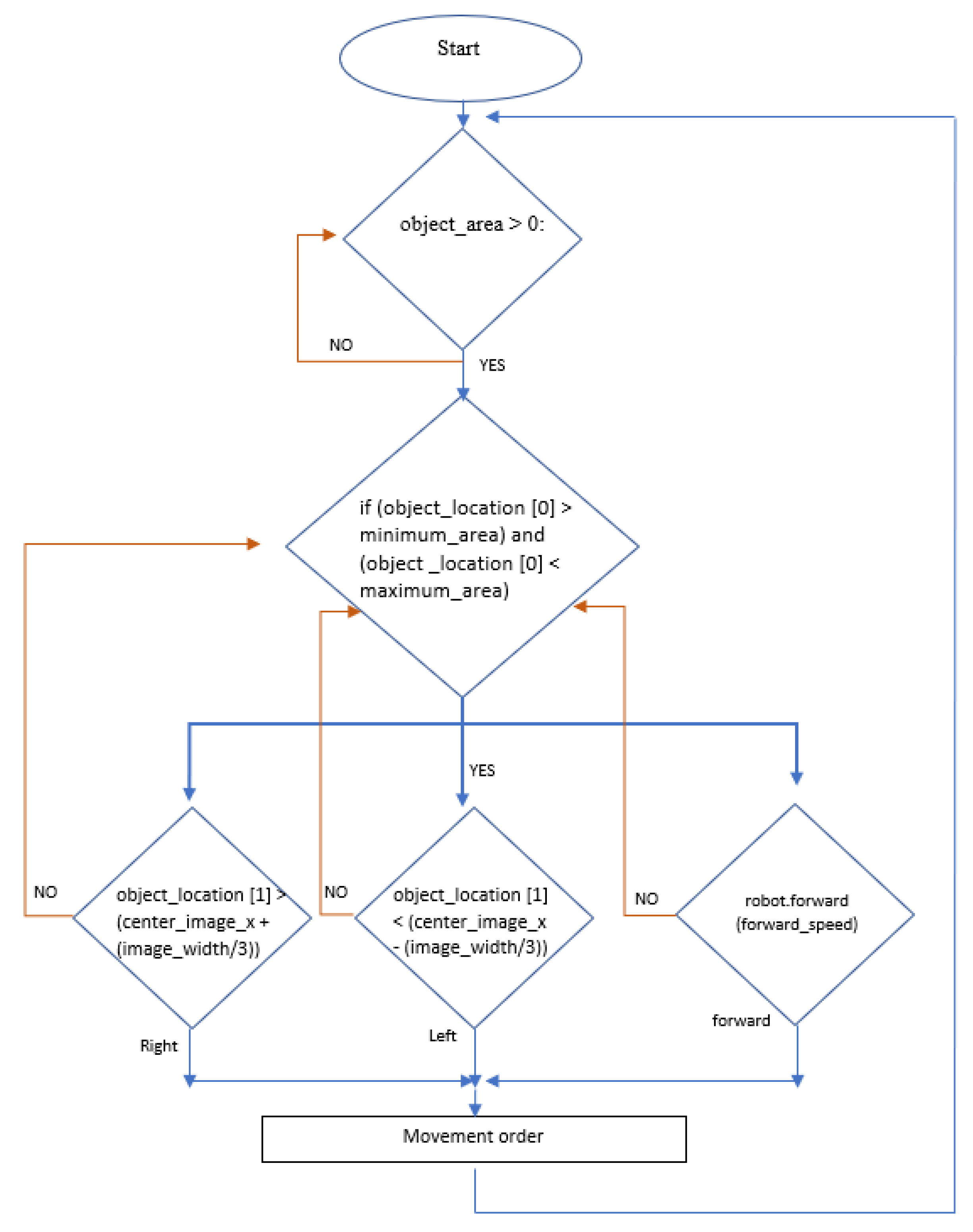
The selected color is used to identify and choose shoppers in crowded areas. The RGB color is detected from the video camera read and then transformed to the HSL color space. The HSL color space causes the chromatic data to be independent of the lighting brightness. According to the object coordinate detection result, the GPIO relays the order to the motor driver to steer the robot in the left or right direction based on the camera filter data. The flowchart of the system algorithm is shown in
Figure 15.
3. Outdoor Airflow Analysis
Temperatures exceeding 41
C can cause fatalities. However, even when there are no deaths, these temperatures can cause people to be unable to shop outdoors. Some groups of people are more vulnerable than others because they suffer from heat stress at lower temperatures. Due to the hot weather and high humidity levels, shoppers cannot shop in open areas due to heat stress. For this reason, the number of customers shopping outdoors is minimal in summer in this region. There are many ideas and techniques to encourage people to go outdoors to roam, including those through technologies that lead to the production of a cool stream of airflow around users in open areas and buildings [
47,
48]. In this work, we used a fixed air cooler in the tracking robot to produce a cool airflow when shopping outdoors. The design of this robot allows cold air to flow onto the user’s back. The robot allows us to cool the shoppers in the market while they are roaming to increase their comfort. As shown in the figure, we used the RIGID Micro DC air conditioner as the most efficient cooling option (
Figure 16). The power source required for a DC air conditioner is 12 volts. This air conditioner reduces the temperature around the shopper as they shop. The compact compressor air conditioner provides an excellent solution for refrigeration with high base factors.
The following cooling parameters are very critical in our simulation and our work:
The miniature compressor uses a brushless electrical DC motor that runs on a 12 V DC power supply. We can change the speed range of this compressor from 2000 RPM to 6500 RPM through potentiometers at 50 kiloohms.
The BTU produced from the air conditioner presents the most critical parameter in this research and the robot prototype [
49,
50]. The air conditioner mounted inside the robot provides 1535 Btu/h of cooling [
51]. According to BTU, the distance between the shopper and the robot should be no less than three feet to ensure that the shopper feels a positive effect.
The cooling power formula is as follows:
where
is the external temperature and
is the temperature difference.
We consider that the outdoor temperature is approximately 40
C during summer. We look to reduce the temperature around the shopper from 40
C to less than 30
C in the range of one meter. This robot can reduce the temperature around the shopper to 30.2
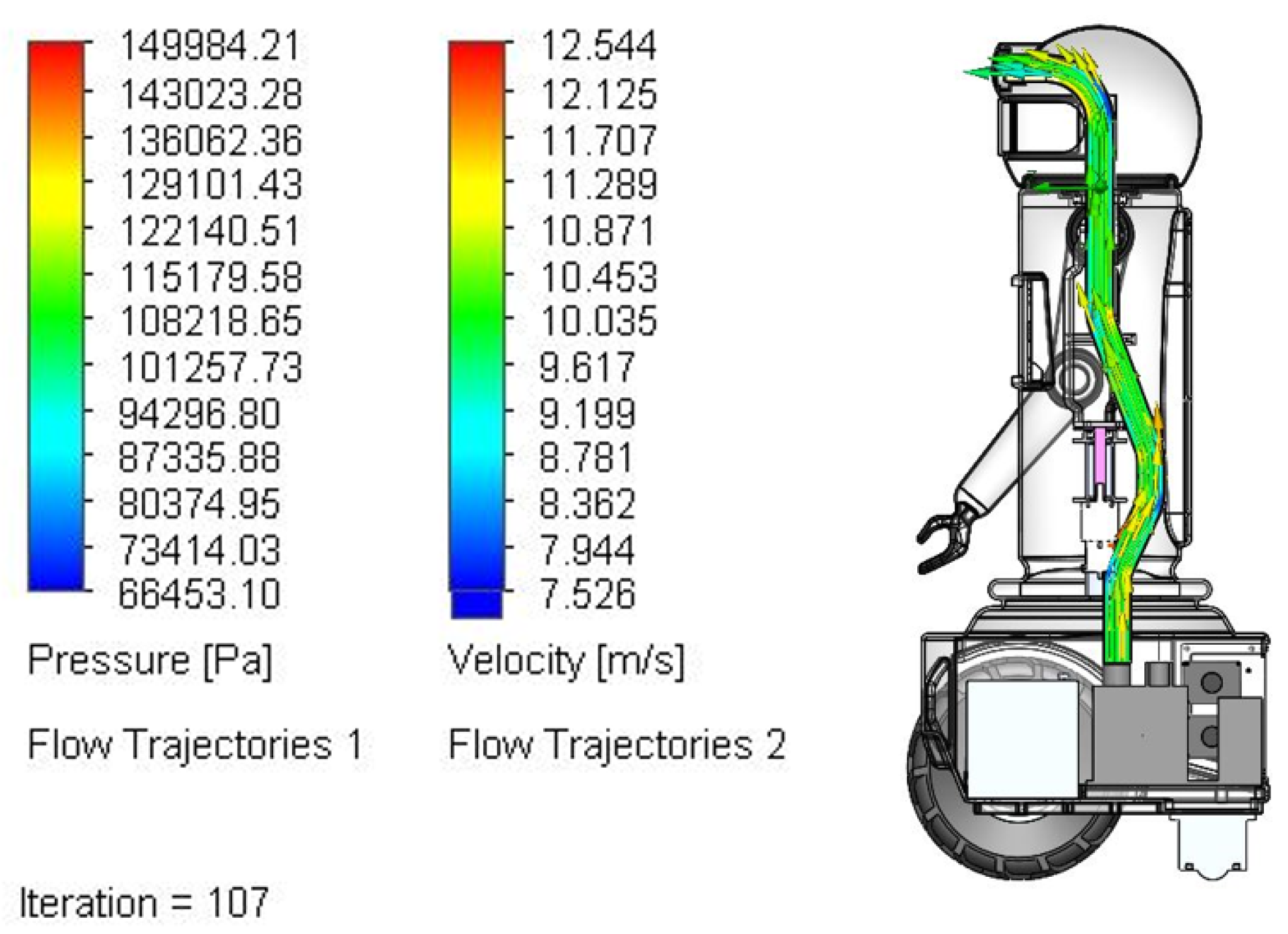
C, which can meet users’ demands. Due to the robot’s size, a very compact air conditioner system is required. With a width of 330 mm and a height of 200 mm, it is compact enough to mount and fix in the robot. The velocity change because of its path is shown in
Figure 17.
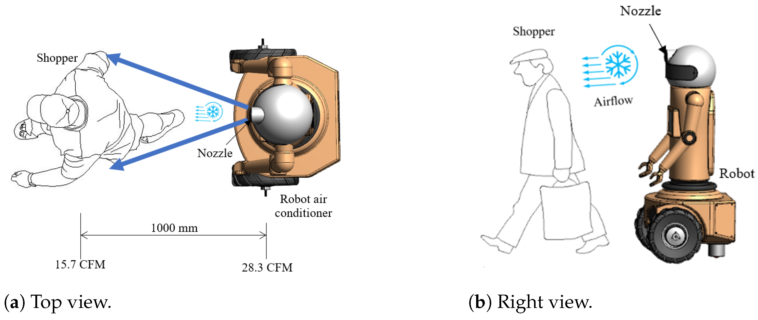
The present work discusses the characteristics of the skin sensation evoked by the airflow to the shopper during their shopping in an outdoor market. The effect of the cool air increases the degree of comfort of the shopper. The equivalent speed of airflow for the user is 28 CFM, which is lowered from the airflow speed of their actual walk. The airflow is produced on the user’s back by an air conditioner of 450 W with a gap distance of around 1000 mm as shown in
Figure 18. The airflow speed is 28.3 CFM (1.63 m/s), which is approximately less than the actual walk speed of the user. The result proposes that the sensation of airflow is suppressed while the movement is performed actively with visual information provided. In this test, two factors—the skin and the vestibular system—are taken into consideration. We fix the airflow to 0.14 m/s at each trial to cancel the perceptual hysteresis in the equality adjustment experiment. The airflow is optimized beforehand to provide a comfortable shopping experience.
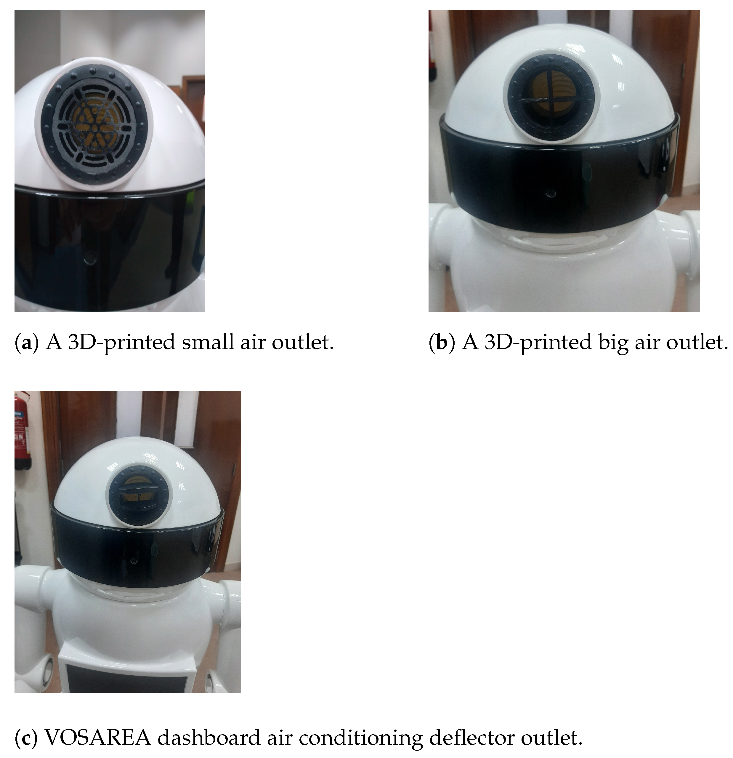
We designed many different air outlets; each has different air directions to vary the air angle and intensity. The 3D-printed nozzle is mounted on top of the robot air conditioner, as shown in
Figure 19.
Figure 19a,b show a 3D-printed ABS small air outlet, 3D-printed ABS big air outlet, respectively; the disadvantage of these above designs is that they are not directional air outlets.
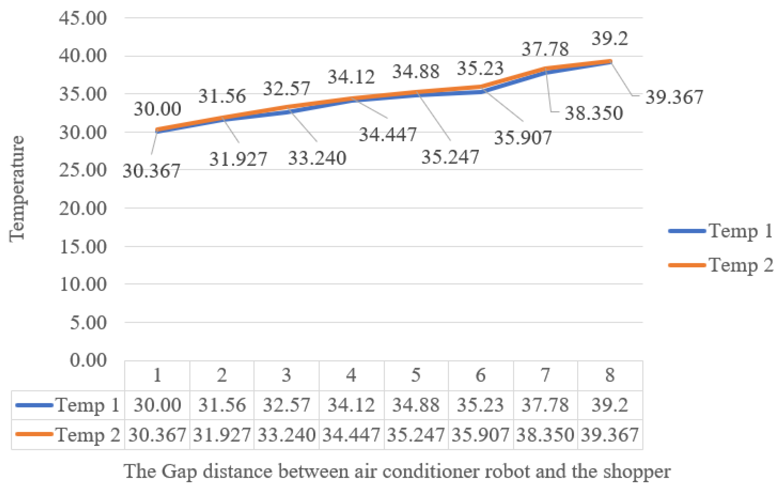
Figure 19c shows a dashboard air conditioning outlet, which gives better results than the 3D-printed outlets in
Figure 19a,b. The present design can reduce the temperature around the shopper and cool the atmosphere around them. According to the stage of calculation and experiment, the robotic air conditioner can lower the temperature difference up to 9.8
C. The smaller the distance between the robot and the shopper, the higher the cooling degree as shown in
Figure 20.
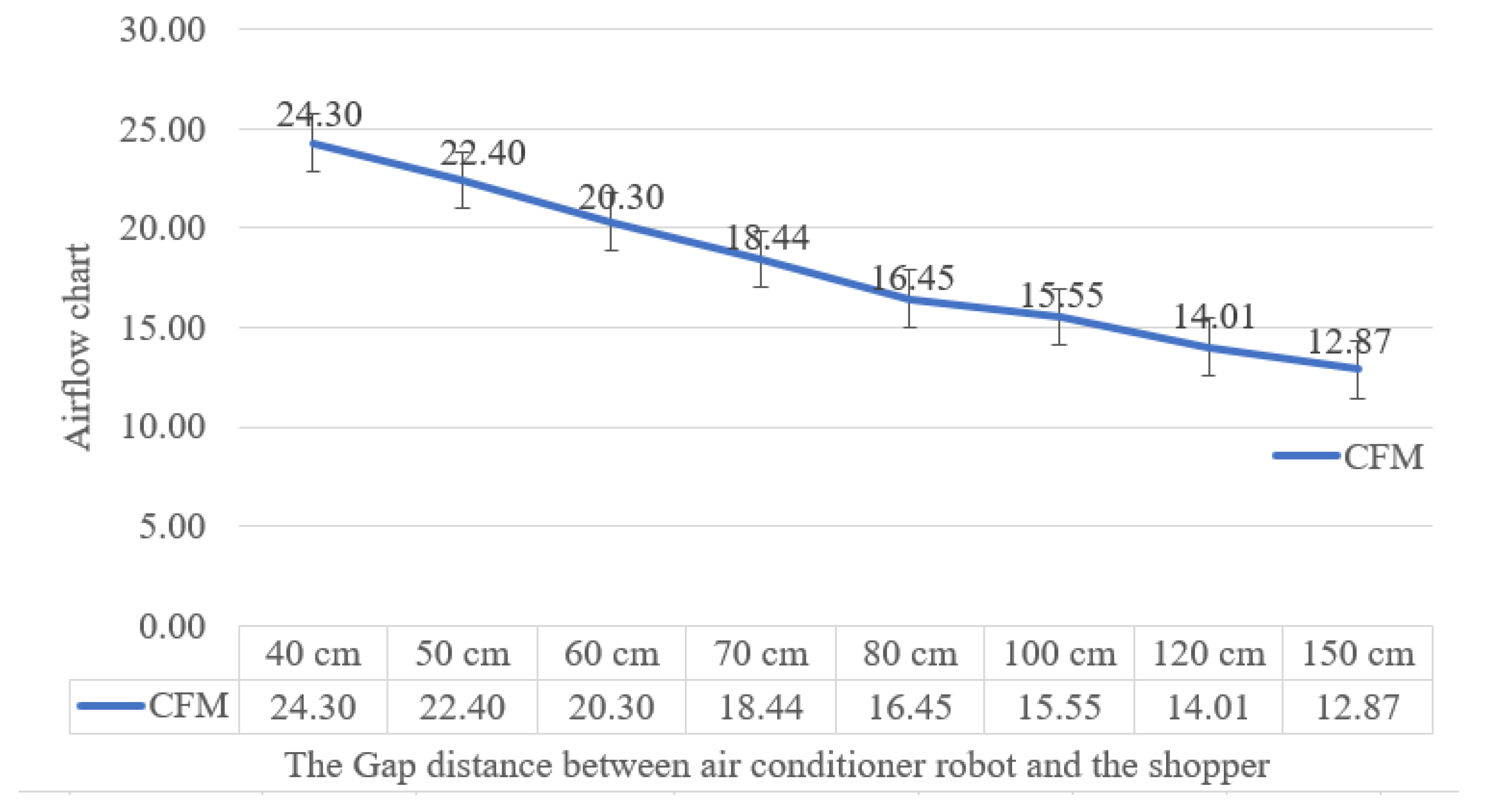
The air flow at a distance of 40 cm is equal to 24.3 CFM and decreases to 12 feet per minute at a distance of 150 cm, which means that the distance between the robot and the shopper should not be more than 60 cm (20.3 CFM) as shown in
Figure 21.
The users noticed an increase in airflow when using the robot. In their evaluation, users felt the source of the airflow that produced the cold air. They suggested several improvements to the model, including higher variability in the airflow depending on the distance gap between the shopper and the robot and more precise air direction.
4. Kinematics of Differential Drive Caster Robot
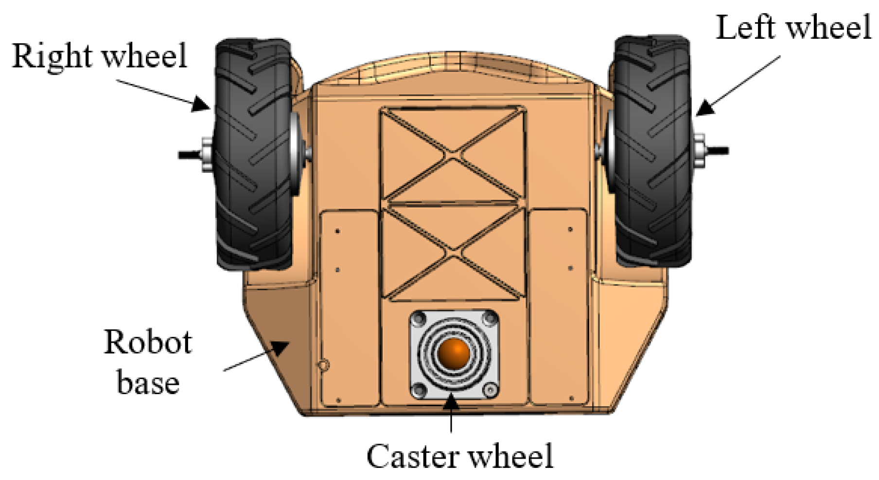
There has been much work on the mechanical frame and platform of this type of robot. The mobile robot used in this prototype study is a differential wheeled robot, consisting of two tires 13
actuated with two independent motors and a free caster wheel that balances the robot during motion as shown in
Figure 22. The air-conditioner robot is driven by controlling the relative velocities of the tires on the right and left sides. After significant research, the model in [
52] was adopted for our application.
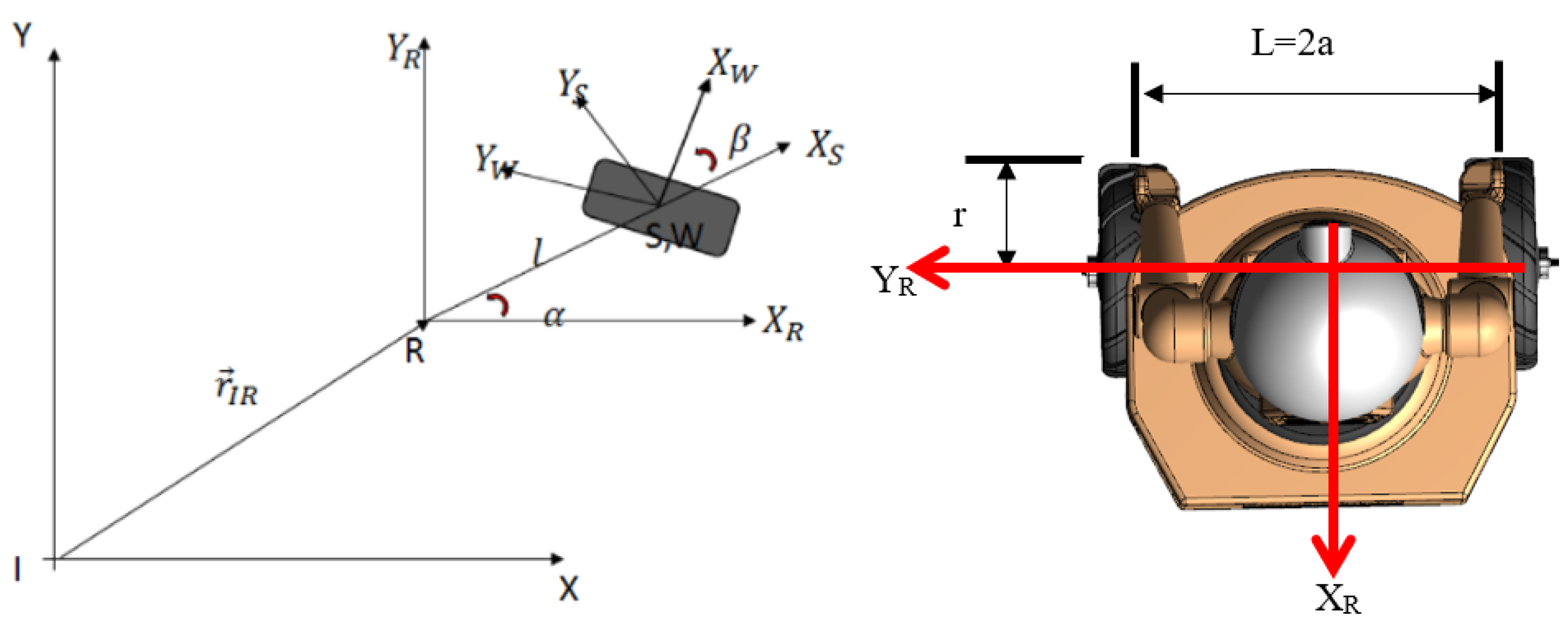
The kinematic parameters and geometry of this air-conditioner robot are defined. The orientation vector and position of the air conditioner robot and its speed are, respectively, as follows [
53,
54]:
The speeds and the angular positions of the left and the right high torque wheels are ((
,
), (
,
)), respectively, as shown in
Figure 23.
In this calculation, we assume that the wheels move without slippage, the guidance axis is perpendicular to the ground, and the point Q synchronizes with the center of gravity G, that is, ‖G‖ = 0.
The following mathematical relations describe the kinematic model of the air-conditioner robot:
The kinematic model is written in the driftless affine form as follows:
where
J is the Jacobian matrix of the robot as follows:
The nonholonomic limitation of the air-conditioner robot is given as
y cos −
x sin = 0. So,
is given by the following:
Then, we can write the nonholonomic limitation as follows:
To obtain the dynamic equations of the robot, we use the Lagrangian function. Lagrange methods derive the dynamic model of the differential robot design as follows:
where
is the translation velocity and
is the angular velocity:
There are three variables to control the robot (
x,
y,
) and two control inputs (motor torques); the system is under-actuated. The relation between the angular velocity
and the linear velocity
of the robot and the rate of change in orientation and position is as follows:
Equation (
21) represents the kinematics of the robot. When
is greater than
, the robot turns to the left of its current position, and the orientation angle increases; if
is greater than
, then the robot turns right. The linear and angular velocities of the robot air conditioner may be related to the wheel angular speeds as follows:
The total applied torque is the sum of linear and angular torques. The linear torque is given by (
) as follows:
The angular torque is given by (
) as follows:
where
m is the weight of the robot;
I is the moment of inertia, center;
l = 2
a is the distance between the two wheels;
r is the radius of each wheel;
is the torque;
I is the inertia;
and
are the torques generated by the left and right BLDC motor; and
is the angular speed of the wheels.
In our design, m = 33 kg, r = 6.5 in, and 2a = 560 mm, which can be used as the expectation.
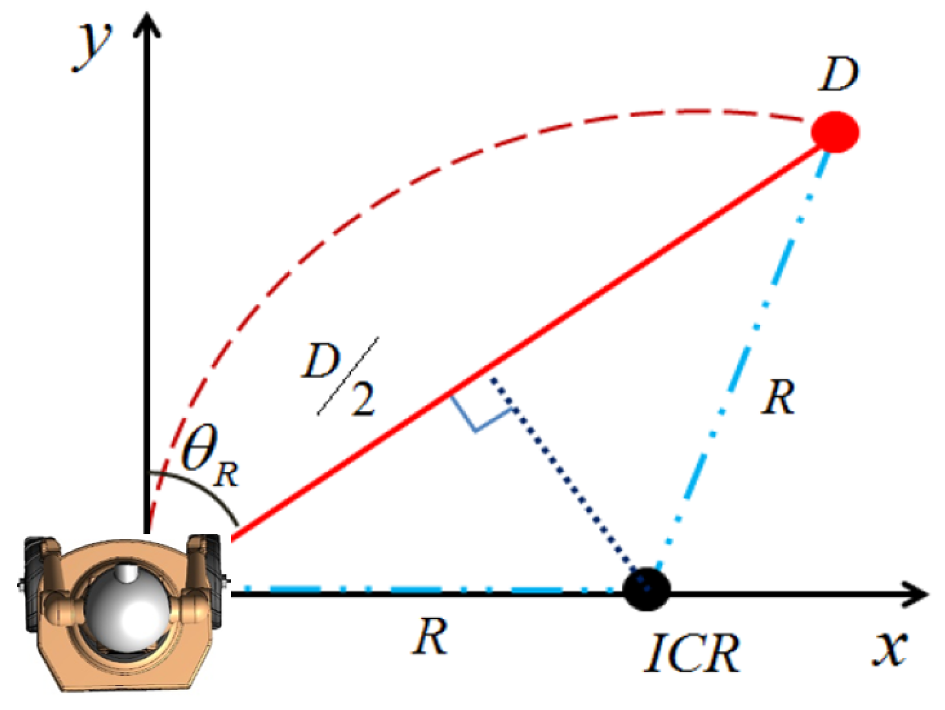
When the robot tries to move to the target shopper after they are recognized, we need to determine the curvature needs based on the subject’s angle and distance. In terms of the robot and the following monitoring, as the radius of rotation increases, the space required to be covered by the air-conditioner robot increases, increasing the time spent moving. If the radius of rotation decreases, the robot wheels tend to slip more [
55,
56,
57,
58,
59]. Therefore, it is essential to select an appropriate radius of orbit for the robot tracking. In this application, when the robot tracks the shopper’s movement, its radius of rotation is determined based on the subject’s angle and distance. The process of moving to the shopper is described as follows in
Figure 24.
Equation (
26) can be used to determine the radius of rotation,
R, as follows:
In this work, the V2 camera is mounted on the center of the robot head, with an angle of view of approximately 88.61
C. The robot used in this work did not use its location sensor to recognize the exterior area, but used the in-built camera to identify the shopper. Equation (
25) is used to calculate the distance that the robot needs.
5. Robot Prototype Discussion
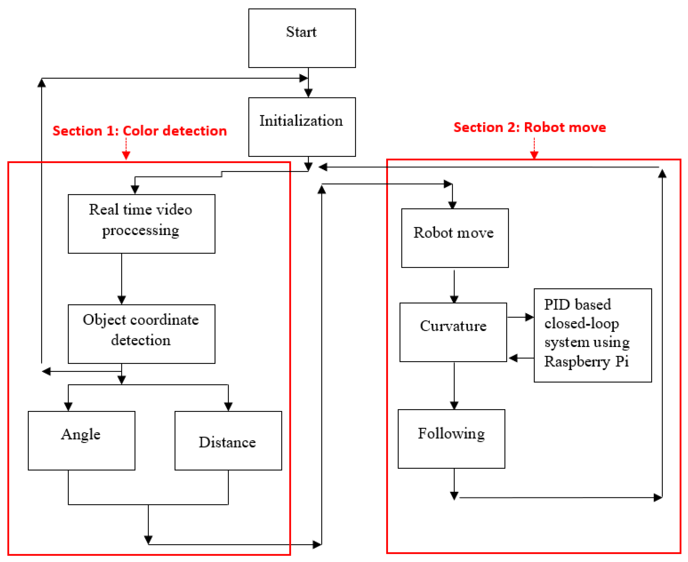
The overall system algorithm presents the following flowchart. After the video read is transferred to the color space and provides the coordinate shopper position distance and angle value, discussed in
Section 1, the data are sent, as discussed in
Section 2, to control the robot (follow, rotate right, or rotate left) as shown in
Figure 25.
We tested the air conditioner robot in different environmental conditions and in two different locations during different times of the day to test the system’s efficiency. The general concept of the air-conditioner robot’s work is presented in the following steps:
Real-time video capture.
Convert video from the RGB color scale to the HSV color space model for more accurate data.
Find the object coordinate position and detection (angle, distance).
Send the direction order via the GPIO pin to the motor drive (left or right) depending on the object coordinate position.
Check that shopper location > minimum area and shopper location < maximum area.
If shopper location > (center image + (image-width/3)), the robot goes to the right direction.
Else: shopper location < (center image + (image-width/3)), the robot goes to the left direction.
Else: shopper location detection in the center of the image, the robot goes to the forward direction.
Elseif: Else: shopper location < minimum area, the robot goes left.
Else: The robot stops because it loses contact with the followed shopper, the robot generates an alarm beep. The robot keeps waiting for the shopper to approach it again to continue the task (detectable range).
The robot uses HSV video analytics to estimate the position of the target shopper base on the PID loop.
The V2 camera captures video in real time, and based on the filter, we can determine the shopper’s coordinates. The robot stays on standby in different market areas and waits for the chosen color to be detected to follow; the robot follows the shopper wearing the jacket. When the robot loses the shopper, it generates a sound of alarm and shuts down its air conditioner.
In
Table 3, the robot’s hardware and mechanical specifications are given.
The list of components used in the prototype are presented in
Table 4.
5.1. Moving Air Conditioner Robot
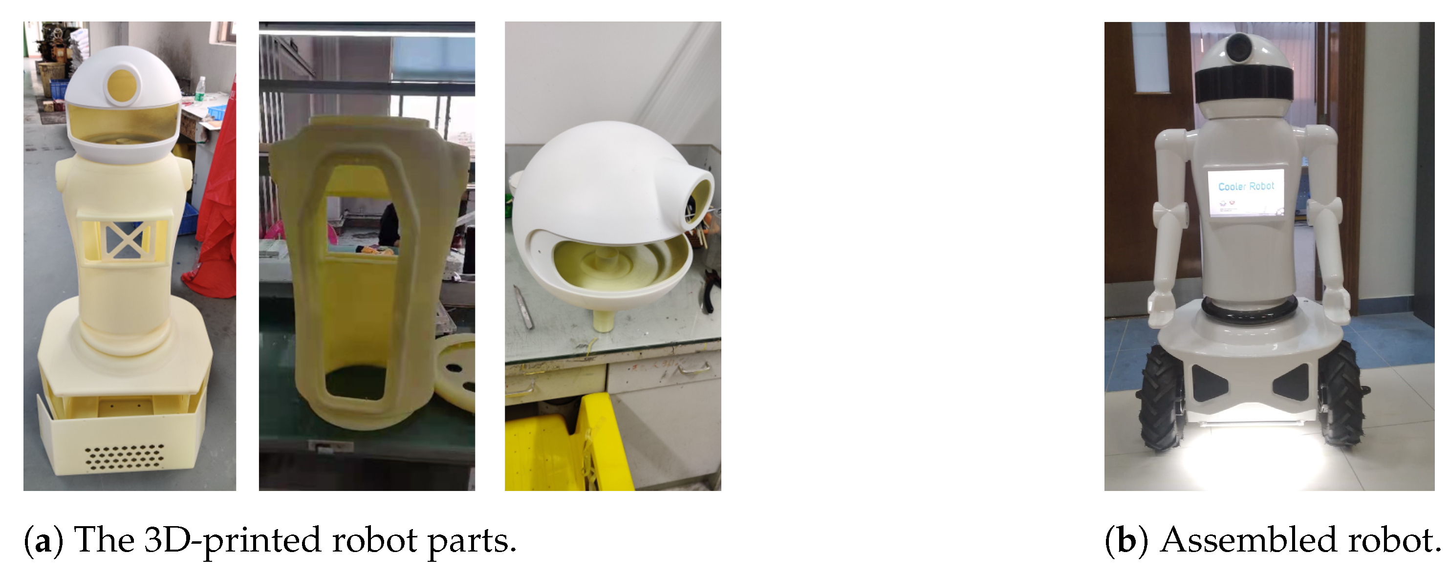
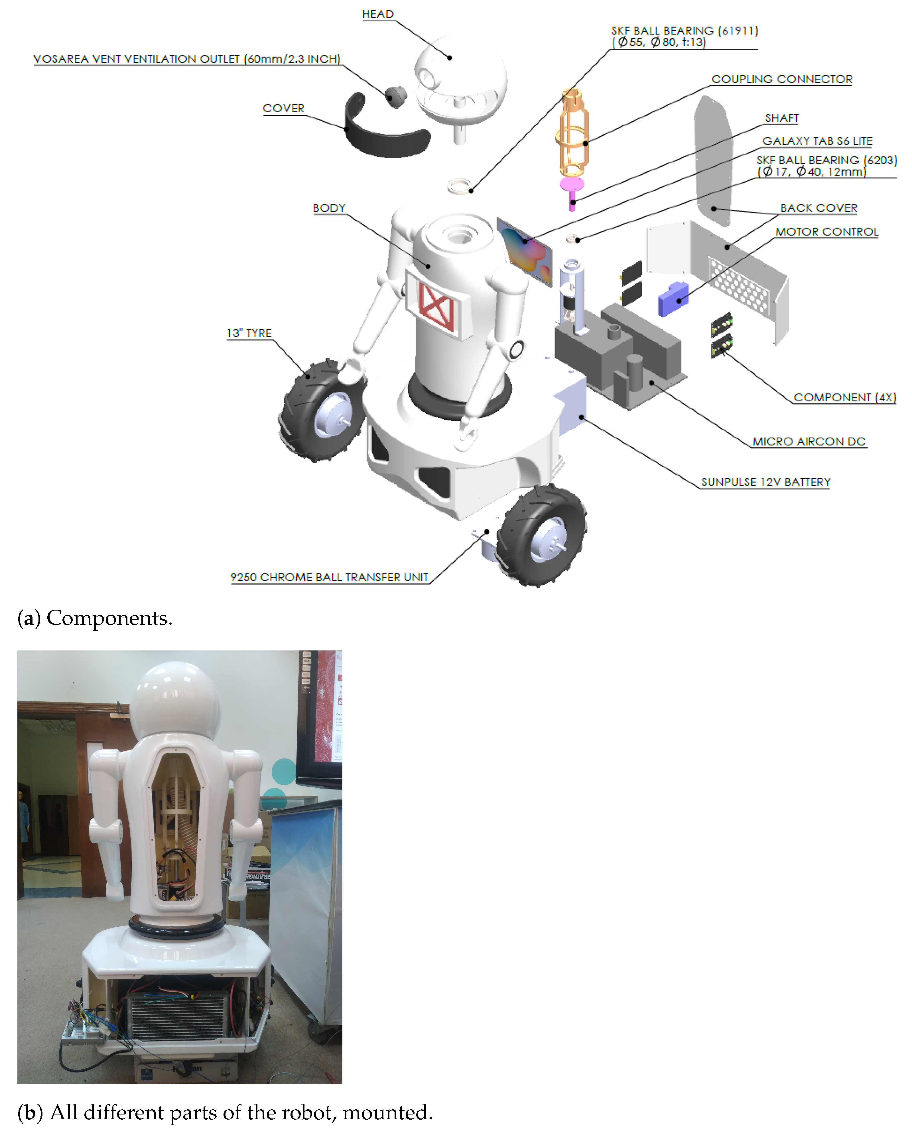
In this work, 3D-printed robots with two wheels were ready for testing. When the V2 camera detects the shopper’s selective color, it automatically follows it. According to the concept described in system synthesis, the system was composed.
This robot was designed in our lab and then printed and fabricated in China. The assembly and the programming phase were in our lab in the Qatar Scientific Club as shown in
Figure 26. A differential drive robot consists of two wheels and a free caster wheel that balances the robot; it moves with the same velocity in two degrees of freedom. The BLDC motor is a 13
single shaft tractor tire geared wheelbarrow motor of the UUMOTOR company. This motor is powered by 500 W, with a max load of 150 kg; its speed ranges from 7 km/h to 10 km/h with a max torque of approximately 59 Nm as shown in
Table 4. We utilized Raspberry Pi camera module V2 to detect the shopper and interact with the computer to accomplish this design. A Raspberry Pi computer controlled the air-conditioner robot to follow the shopper’s movement.
For whatever reason, if the shopper runs, the robot will speed up to catch up with the running shopper; if the shopper’s speed is higher than the robot’s speed, it will stop moving and issue an alarm.
5.2. Design of Mechanical Structure
The robot’s mechanical structure comprises two parts. The base consists of a two-wheel differential drive system (13-inch tractor tire wheelbarrow hub motor) in the front, a flange-fitting ball in the back, an air conditioner cooling system, and batteries as shown in
Figure 27. We designed the body to keep the camera sensor on the top of the robot, mounted on the robot’s head. The camera’s position approximates a person’s height for better visual data with low noise. So initially, the camera location was set up at 1350 mm.
The system design consists of a computer unit and a control unit. The processing unit only uses a camera and is linked with the control unit to transmit the visual information after bulk processing serially. The control unit is connected with the computer, and it makes use of the ultrasonic sensor. The ultrasonic sensor and camera work in unison with each other and helps the air-conditioner robot in its operation to navigate its path by avoiding obstacles and maintaining a specific distance from the object. These decisions are made based on information obtained from the sensor. The generalized system design incorporates a camera and sensor. Looking at the system design, the first phase is detecting through a camera and carrying out substantial processing in the processing unit. The processor that we used is the Raspberry Pi single-board computer. After detecting the color (the jacket), the next phase establishes communication between the processor and control unit. We used a relay board as the control unit. A relay-based motor driver module is used to control the motor drive (speed-mode controller MX25-DC). The advantage of this relay-based module is that it can quickly drive the high torque motors that require large fluxes.
5.3. Power Calculation
In this prototype, we have two power sources:
Battery 12 Vdc 35 AH: For the air conditioner system, 450 W, and Raspberry Pi supplies 10 W (total 460 W). It lasts for less than one hour (approx. 55 min).
Battery 36 Vdc 5.5 AH: For two motors at 500 W each total, it is 1 KW for the full load and full speed. However, we load it with less than 0.3 of the full load and run it at less than half speed. So the total motors power is approximately equal to 300 W. It lasts for more than 40 min. The total energy production of the robot is 1.4 kWh = 0.69 CO2 kg emission (CO2 is meager).
6. Following Experiment
The experiment phase gives us a better idea about the accuracy of the proposed algorithm and the efficiency of the air-conditioner robot. Each test performed takes about 15 to 20 min as a testing phase in different light conditions. We tested our compatibility between the software and the mechanical platform in different directions inside the lab, and we checked the error distance and the efficiency when we fix a small target on the clothing of the shopper before using the robot, as is shown in
Figure 28. The change of angle lightness was more significant than
Figure 28a.
Figure 28b is when the target marker moves from a bright hall to a dark corridor.
Figure 28d is when the target person walks from a dark entrance to a bright hall, opposite to
Figure 28c. The efficiency of this idea is meager; the user can lose contact with the robot many times because the binary image is very low. We conclude that the yellow label is very small in size and the algorithm can easily lose contact with the followed shopper.
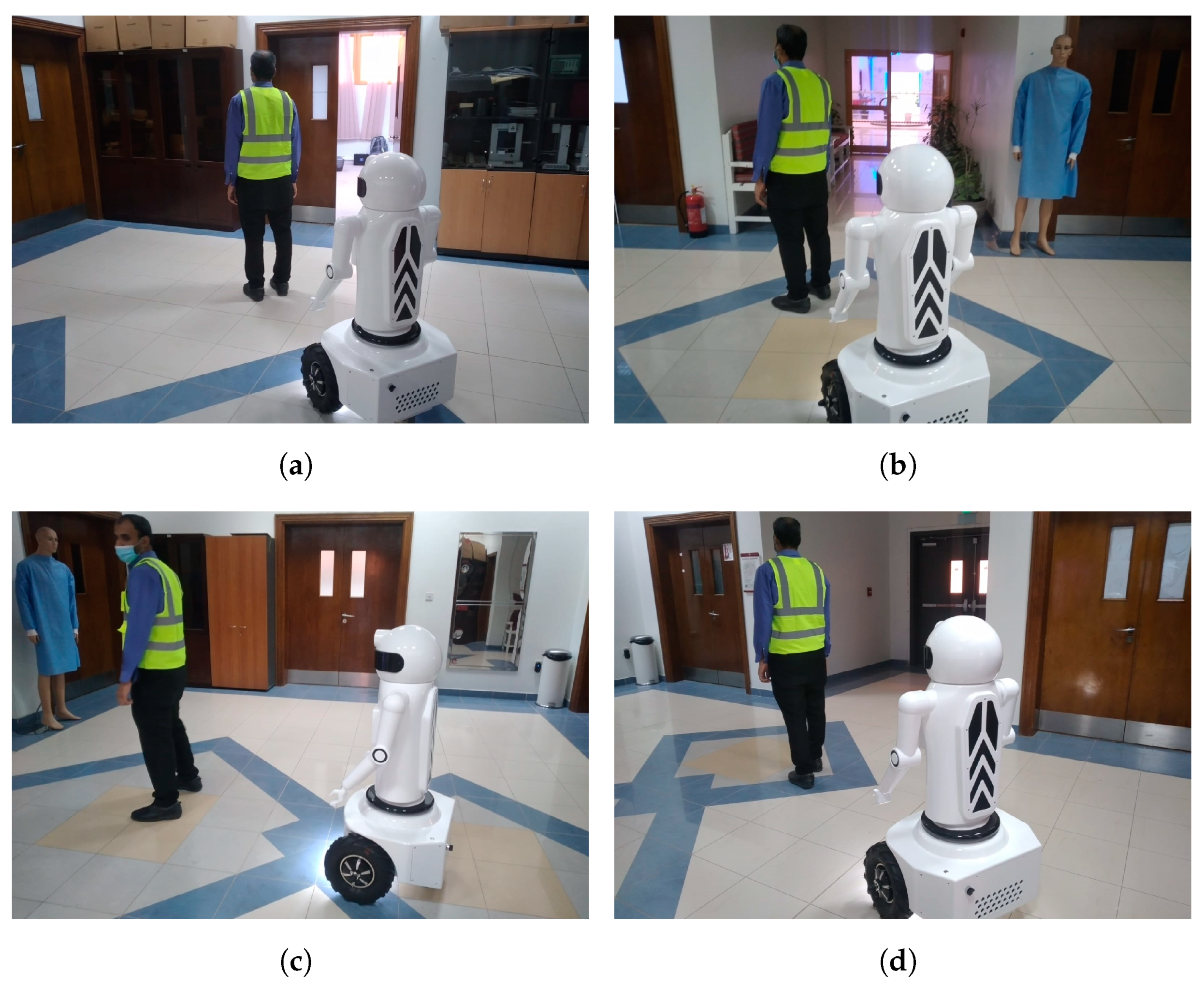
Based on the results obtained from these tests and experiments, we made the necessary changes in the processing and control algorithm and changed the nomenclature. We changed the label to the yellow safety vest, this gives the robot more efficiency and reduces the loss of contact with the robot. A running experiment was carried in the corridor of our department. In this test phase, the target person turned once, right and left. The running scene is shown in
Figure 29. We often carried out the following experiment and measured the error distance and trajectory between the robot and the target person.
Figure 29a is a photo which was taken in the lab hall during the daytime, and the change in brightness is insignificant (sunlight), and the fluorescent lamp is reflected in the hall.
Figure 29b is a photo taken in our lab with a low fluorescent light reflected. The change in brightness is larger than that in
Figure 29a.
Figure 29c is when the target person moves from a bright hall to a dark hall.
Figure 29d is a scene where the target person walks from a dark hall to a bright hall, opposite to
Figure 29c. In this test, the target person moves left and right and from right to left. The moving trajectory scenario is shown in
Figure 29. In this photo, from
Figure 29a–d, the robot follows the target smoothly, and the robot shows high flexibility to move and follow with low error. We conducted this following process experiment many times, and we measured the error following the distance between the target person and the robot. After measurement, the error tracking distance was around 30 cm and this shows that a good result was obtained. The robot has the ability to track the robot in different lighting conditions, as shown in
Figure 29a–d. Experiments have shown that the efficiency of the jacket is higher and better than the yellow label.
We conducted ten experiments for both the marker tag and jacket. We noticed that the low-repetition label (50%) and the high-repetition jacket had good efficiency (90%), as shown in
Table 5.
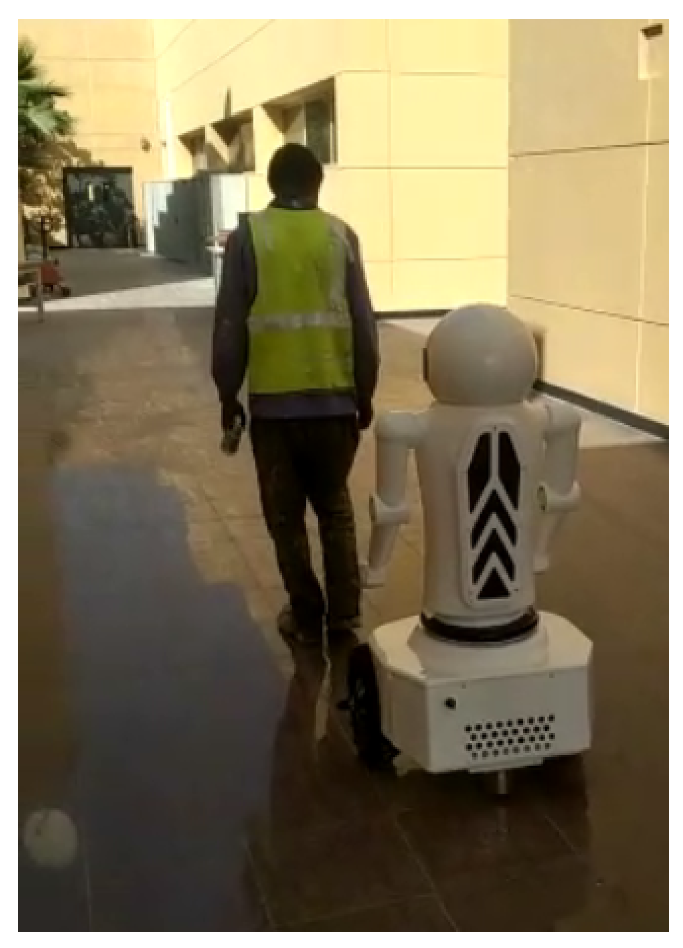
The final test phase consists of fusing all the information obtained by the sensor camera and modules in the computer unit. Hence, the control unit makes an intelligent decision to change the robot’s direction, and the shopper follows with a yellow colored tag in an outdoor test as shown in
Figure 30.
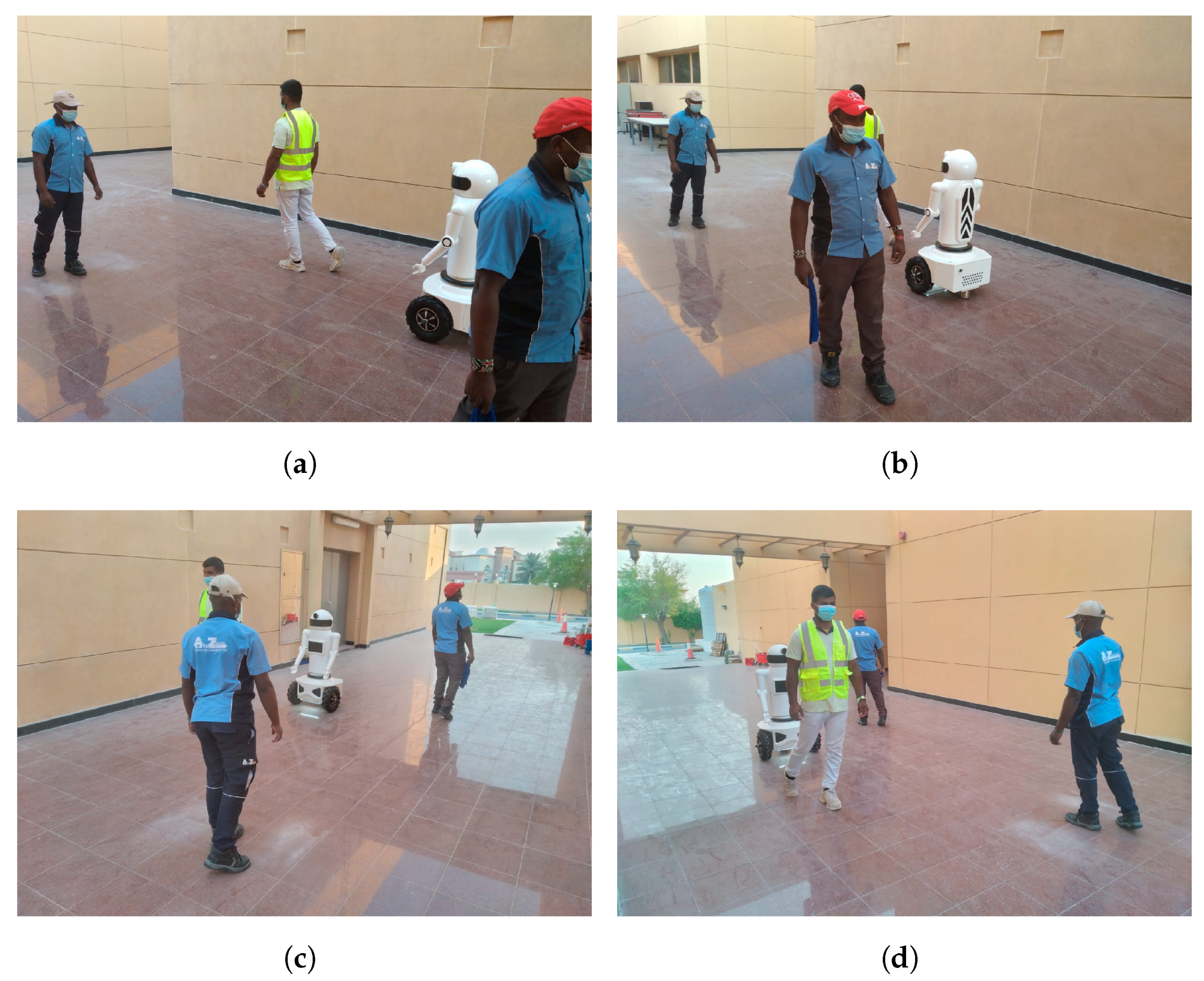
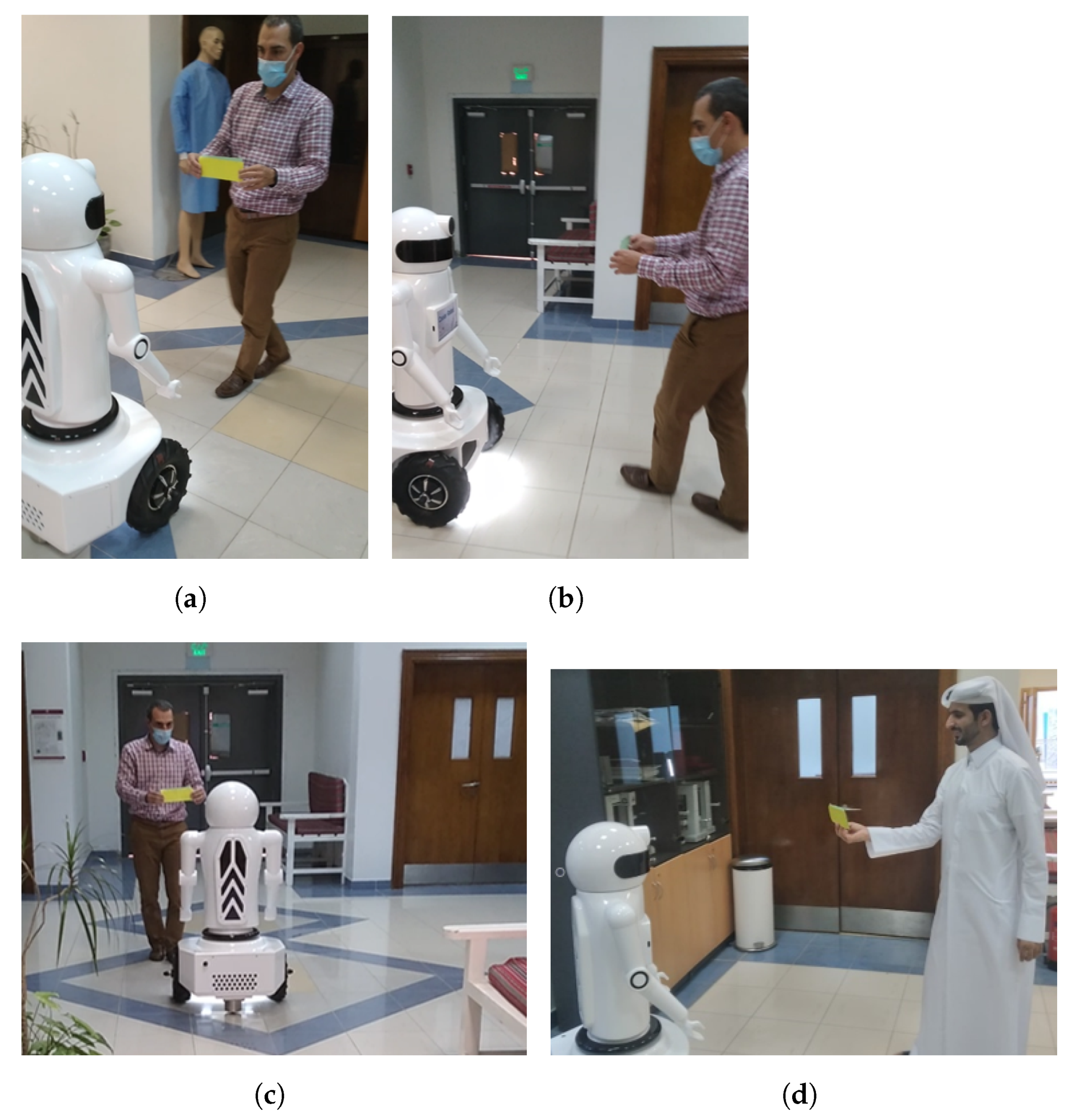
At the present time, every shopper who wants to use an air-conditioner robot while shopping at the open market needs to wear a unique yellow jacket. We are working on making a comfortable jacket. We cannot use face recognition in this application because this open market is a public area. We cannot do training for all shoppers before using the robot, so the easy solution is to wear a comfortable jacket during shopping. The main objective of this robot is to produce cool air with high airflow propagation around the shopper. We test the air conditioner robot in crowded areas to determine the system’s response in vivid regions, as shown in
Figure 31. In this test, we registered four scenes in
Figure 31a–d of the following mode in different seniors. Scene
Figure 31a is a scene of the shopper move in an open area with high lightness. Scene
Figure 31b is a scene in which we increase the number of people around the robot, but we do not lose contact with the robot. Scene
Figure 31c, the robot follows the person wear the jacket with low lightness. Scene
Figure 31d is a scene where the shopper walks from a vivid area to a quiet crowded area. We observed that the jacket gives better performance than the marker; after many iterations, we lose the air conditioner robot negligibly if the human walks abnormally.
We test the air conditioner robot in crowded areas to determine the system’s response in vivid areas as shown in
Figure 31. We observed that the jacket gives better performance than the marker; after many iterations, we lose the air conditioner robot negligibly if the human walks abnormally.
The test involves the air-conditioner robot moving across an open space with different illumination conditions and a mobile background. The target person walks into the open area. The air conditioner robot follows the person wearing a unique jacket at a distance of one meter; where the target moves, the open space is narrowed in various positions.


