Article

Dynamic Frequency Support for Low Inertia Power Systems by Renewable Energy Hubs with Fast Active Power Regulation

1
Department of Electrical Sustainable Energy, Delft University of Technology, Mekelweg 4, 2628 CD Delft, The Netherlands
2
TenneT TSO B.V., 6812 AR Arnhem, The Netherlands
*
Author to whom correspondence should be addressed.
Electronics 2021, 10(14), 1651; https://doi.org/10.3390/electronics10141651
Submission received: 26 April 2021 / Revised: 2 July 2021 / Accepted: 9 July 2021 / Published: 11 July 2021
(This article belongs to the Special Issue Real-Time Applications for Power-Systems)

Abstract

:
This paper concerns the feasibility of Fast Active Power Regulation (FAPR) in renewable energy hubs. Selected state-of-the-art FAPR strategies are applied to various controllable devices within a hub, such as a solar photovoltaic (PV) farm and an electrolyzer acting as a responsive load. Among the selected strategies are droop-based FAPR, droop derivative-based FAPR, and virtual synchronous power (VSP)-based FAPR. The FAPR-supported hub is interconnected with a test transmission network, modeled and simulated in a real-time simulation electromagnetic transient (EMT) environment to study a futuristic operating condition of the high-voltage infrastructure covering the north of the Netherlands. The real-time EMT simulations show that the FAPR strategies (especially the VSP-based FAPR) can successfully help to significantly and promptly limit undesirable large instantaneous frequency deviations.

1. Introduction

Frequency is a systemic parameter, which ideally stays at a constant value, e.g., 50/60 Hz, at all voltage levels. However, when a power system is subjected to sudden perturbations, such as the loss of components, increase/decrease in load, or other events that cause load-generation imbalances, dynamic frequency excursions are excited [1].
The time evolution of the frequency of conventional power systems is usually bounded within well-defined technical limits. Acceptable Rate of Change of Frequencies (RoCoF) and maximum frequency deviations (a.k.a. frequency Nadir/Zenith) have been largely ensured due to the predominance of conventional power plants with heavy rotating synchronous generators [2]. On one hand, such heavy machinery has traditionally entailed an inherent opposition (i.e., high inertia within a time frame of several milliseconds) against steep RoCoF, whenever a sudden perturbation of the active power balance occurs [3]. On the other hand, conventional plants performing primary frequency control have traditionally offered enough headroom for proportional adjustment (within a time frame of several seconds) of their active power output to prevent the violation of the allowed Nadir/Zenith [4].
Due to environmental concerns, conventional power plants, especially fossil-fuel-fired plants, are being progressively phased out. This is leading to a significant reduction in the level of inertia and the absence of the major players of primary frequency control. In this context, the violation of the limits of RoCoF and Nadir/Zenith is a major cause of concern [1]. Currently, significant research efforts are devoted to the development of new active power–frequency control concepts, i.e., Fast Active Power Regulation (FAPR), in an attempt to improve the dynamic frequency support that could be offered by power electronic interfaced devices (e.g., voltage source converters—VSCs—applied in renewable plants, responsive demand, and controllable storage and compensation elements) [5,6].
To date, most of the established power electronic interfaced devices perform system-integration-oriented control actions under a grid-following approach, i.e., the network-side VSC unit adjusts the current injection according to the reference signal defined at the point of common coupling (PCC). In principle, there is no mechanical power used to directly support the system’s frequency control. Solar photovoltaic (PV) generation is a classic example of a fully decoupled (Type-4) renewable plant, in which the priority is to generate the highest possible amount of active power based on a so-called maximum power point tracking (MPPT) characteristic [7]. Since VSC-interfaced solar PV generation does not involve any rotating element on the DC side of the network-side VSC, the main option for fast active power–frequency control actions at the AC side of the network-side VSC is by modifying the MPPT, which entails a reduced margin for active adjustment [7].
Type-4 wind turbines are becoming a preferred option for new wind power plants. Due to decoupling from the power system by a back-to-back converter, wind turbines do not directly react to perturbations occurring in a power system. In this way, the natural inertia that could have been extracted from the wind turbine cannot be fully and promptly deployed [8]. Furthermore, the VSC units belonging to HVDC systems [9], or responsive demand (e.g., large-size electrolyzers [10]), could be involved in fast active power–frequency control. Nevertheless, the active power set points required to fulfil the required power transfer may restrict the headroom and speed of active power adjustment. Alternatively, hybrid resource-based solutions are receiving more attention for future developments, e.g., flywheels combined with tidal and biogas-based generation [11], and hybrid energy storage systems placed at renewable power plants [12]. Obtaining enough levels of headroom for effective fast active-power control, under highly variable operating conditions in systems with very high shares of VSC-interfaced devices, remains an open research challenge.
In view of the above review, this paper concerns an investigation of the feasibility and effectiveness of FAPR, when implemented and deployed in a renewable energy hub comprising a solar PV farm and a proton exchange membrane (PEM) electrolyzer. Unlike the current state of the art, the paper provides insight on the degree of improvement of the frequency response of a power system, as affected by individual and collective fast active power adjustment of the controllable elements belonging to the hub. Among the selected strategies are droop-based FAPR, droop derivative-based FAPR, and virtual synchronous power (VSP)-based FAPR. The FAPR-supported hub is interconnected with a test transmission network, modeled and simulated in a real-time simulation electromagnetic transient (EMT) environment to study a futuristic operating condition of the high-voltage infrastructure covering the north of the Netherlands.
The reminder of the paper is structured as follows: the characteristics of the test system are presented in Section 2, whereas the implemented energy hub is described in Section 3. The rationale behind the applied FAPR strategies is overviewed in Section 4. Numerical results are shown in Section 5. Finally, Section 6 summarizes the concluding remarks.

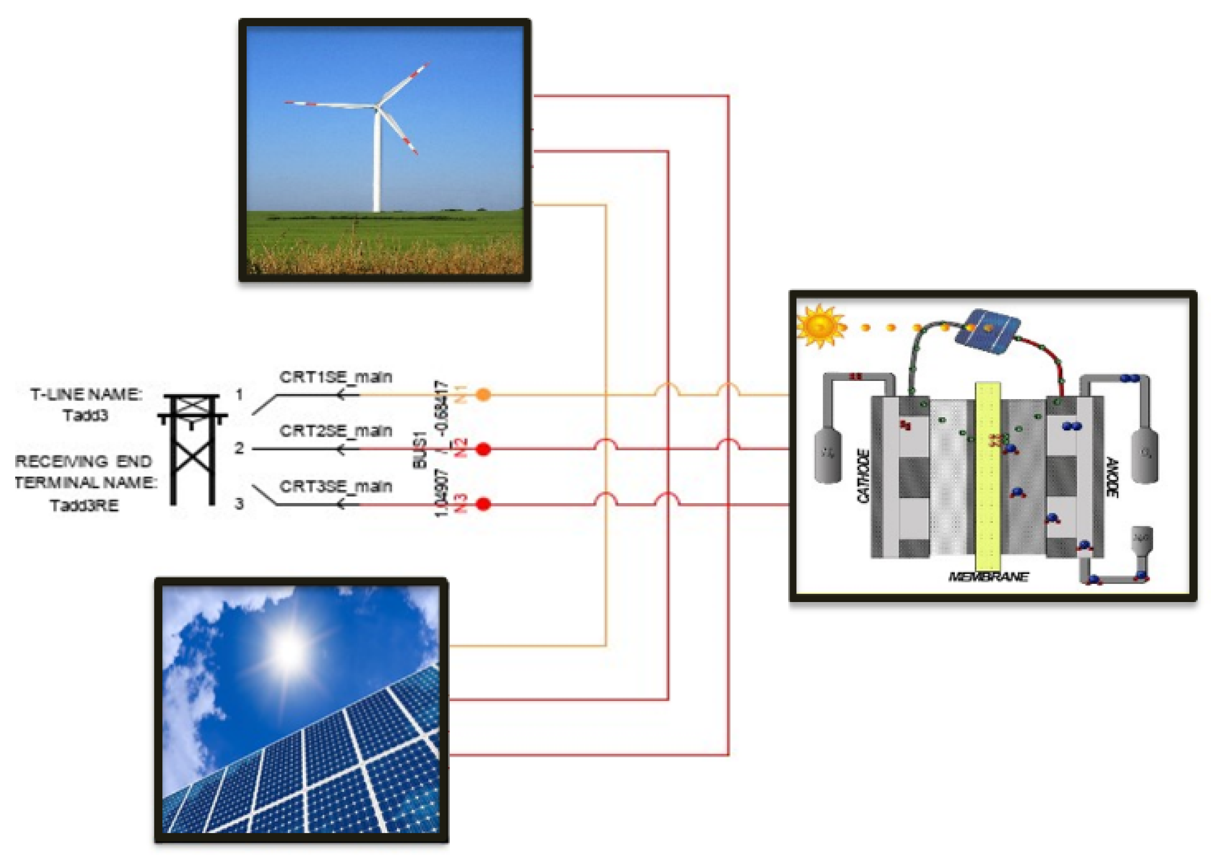
2. Description of Test Model of the North of the Netherlands Network (N3)

The test model was built by using RSCAD software and inspired future operational scenarios and expansion plans presented for the future Dutch power system [13]. In a hypothetical future scenario (e.g., the year 2030), the installation of a large-scale electrolyzer plant is assumed to happen in the north of Netherlands. This part of the network includes a large-scale generation center, the connection of large-scale offshore wind plants, and submarine HVDC interconnections with Norway (NorNed) and Denmark (COBRAcable) at Eemshaven and Eemshaven Oudeschip substations. Eemshaven Oudeschip is also a suitable location for a future 300 MW electrolyzer plant, as abundant renewable energy generated by the offshore wind farm can be converted into hydrogen gas. The electrolyzer plant can also support the power system stability by participating in ancillary services. The modeled system covers the extra-high voltage (EHV) infrastructure of voltage levels 380 kV and 220 kV, and the year 2030 is taken into account to create synthetic profiles of generation and demand. The system also features two 2250 MVA thermal power plants, each one equipped with two synchronous generation units. Additionally, renewable energy is exchanged via the HVDC inter-connectors with Denmark (COBRAcable) and Norway (NorNed), both operated at the rated power transfer capacity of 700 MW. Apart from this, the test N3 network houses 3058 MW onshore wind energy and 600 MW of offshore wind energy (Gemini wind park) distributed around the area, which further aggregates into their corresponding 380 kV substations.
The synchronous generators models illustrate dynamic behavior due to detailed steam turbine governors enabled with droop control, AVR (Automatic Voltage Regulators) and PSS (Power System Stabilizers). This supports dynamic control and the provision of ancillary services during disturbance and post-disturbance periods. Wind turbines were represented by generic models, which are available in the software. For this study, it is assumed that the HVDC inter-connectors did not participate in the regulation of the system. Additionally, the local demands were clustered and modeled as constant loads. Figure 1 represents the load flow results of an N3 network of scenario 2030 [13].

3. Modifications Performed in the N3 Network to Integrate Elements Equipped with FAPR

Three main modifications were undertaken in the N3 test system for the sake of the analysis of its frequency stability. Option 1: a 300 MW PEM electrolyzer with FAPR placed at EOS (cf. Figure 1). Option 2: a solar farm of 300 MW with FAPR. The loads in the N3 test system were increased according to the projected growth by year 2030. In this condition, the N3 test system was prone to congestion, and the occurrence of an active power imbalance excited dynamic frequency excursions.

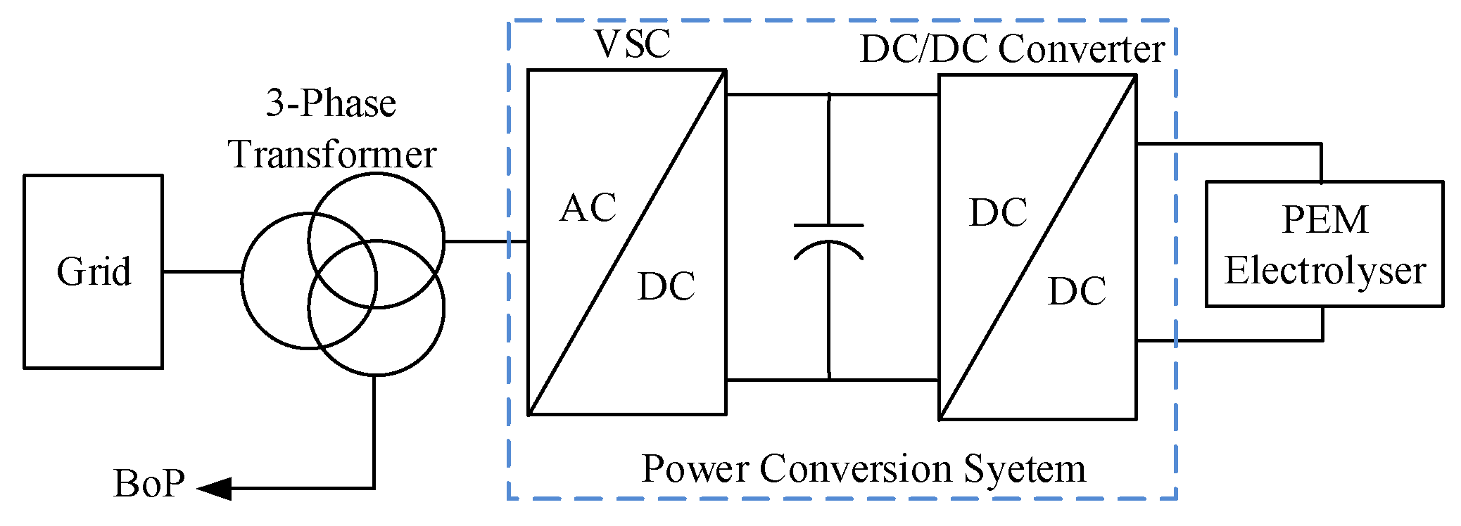
3.1. Representation of a 300 MW Electrolyzer

Figure 2 illustrates the interconnection of the 300 MW PEM electrolyzer, which constituted an aggregated model representing a farm of 300 electrolyzers, with 1 MW electrolyzer model scaled up to a model of a 300 MW electrolyzer farm. The derivation and testing of the model can be found in [13].

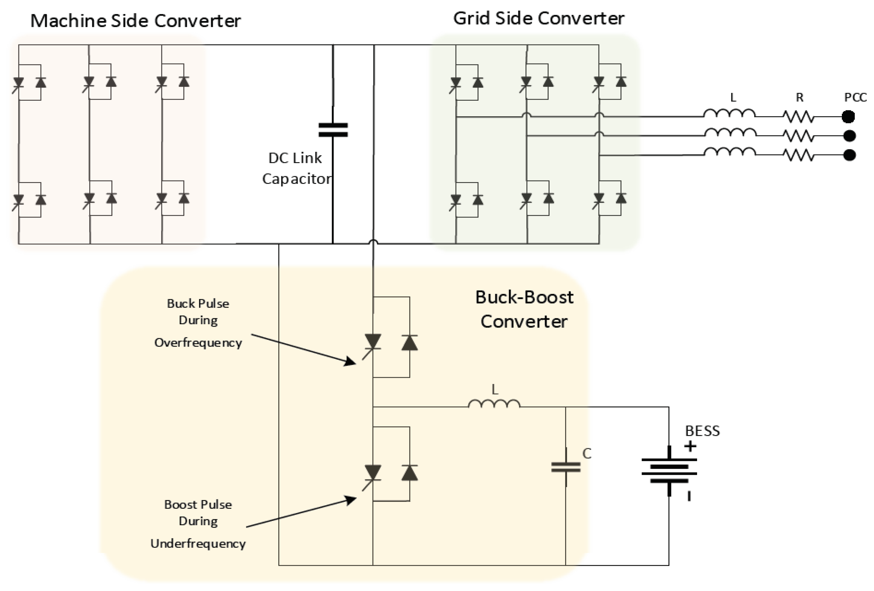
3.2. Representation of a Type 4 Wind Turbine and Type-4 Solar PV Farm

Figure 3 represents the connection diagram of the Type-4 renewable power generation (i.e., wind or solar PV) plants indicated in Figure 4. Note that the generators of these plants are equipped with a battery energy storage system (BESS), which is connected to the corresponding back-to-back link by using a DC-DC converter. The FAPR strategy adjusts the BESS to provide fast active power–frequency support through the grid side converter.

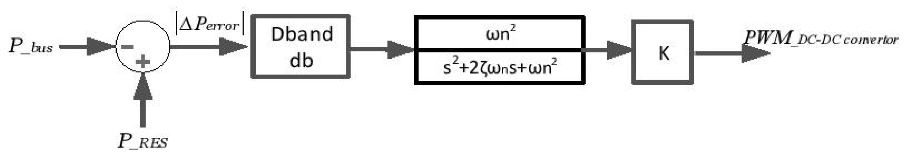
4. Selected FAPR Strategies

FAPR constitutes a supplementary control acting on power electronic converters that link renewable generation, or storage, or controllable demand with an electrical power system. The input signal can be the measured system frequency and/or the deviation of active power. Next, a defined control structure dynamically adjusts the injection/absorption of active power in an attempt to quickly bound the frequency deviation resulting from a sudden active power imbalance.

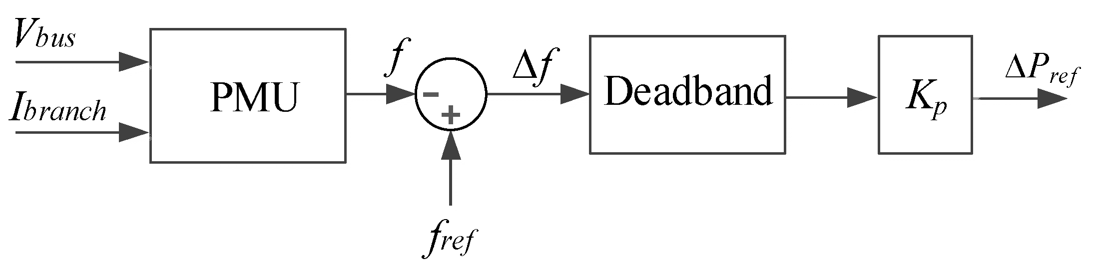
4.1. Droop-Based FAPR

Frequency droop control adjusts the active power following a linear characteristic. Figure 5 illustrates the droop-based FAPR. Here, f represents the measured system frequency at the PCC. fref is the frequency set-point.
The error between the two input signals is passed through a deadband. According to some grid codes [16], the primary frequency controllers shall be activated when the frequency deviation is beyond 0.06% to 0.1% from its nominal value. Based on this, the deadband can be defined to be between 0.03 to 0.05. In this study, the deadband was chosen to be 0.03, to account for a high sensitivity of the controller. The resulting signal is multiplied with a proportional or droop gain 𝐾p. The value of 𝐾p is system dependent. It is tuned based on the possible energy extraction from the wind turbine considering both grid-side requirement and wind turbine-side requirement [5].

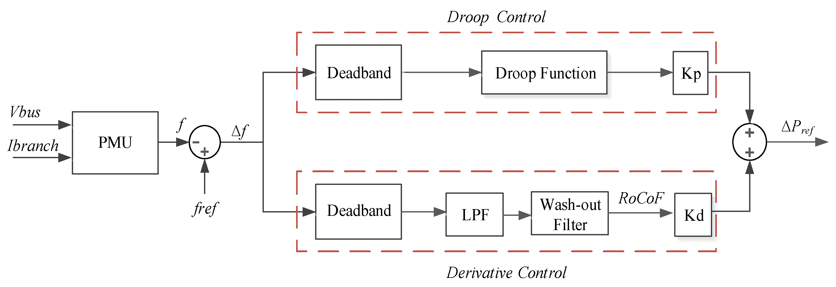
4.2. Droop Derivative-Based FAPR

Figure 6 illustrates the droop derivative-based FAPR. The set-point fref and the measured frequency f constitute the inputs of the controller. The frequency deviation Δf is passed through two parallel control loops: the first one is a droop controller, which works as described in the previous section. The actuation of the droop controller is active for the entire frequency containment period. The second loop is a derivative control, whose output is a derivative gain of the frequency error signal. The derivative controller is only active for the initial few milliseconds to a few seconds, and lasts until the frequency response stabilizes at the maximum allowed frequency deviation. The combined effect of the outputs of the droop-based loop and derivative-based loop produces ΔPref, which modulates the active power response of the device(s) to improve both RoCoF and maximum frequency deviation (e.g., Nadir).
The droop derivative FAPR strategy should be tuned (taking into account system-dependent dynamic properties) to cause a prominent ramping of the active power output at the AC side of a grid-side converter, whenever an over/under-frequency event occurs [5].

4.3. VSP-Based FAPR

Figure 7 depicts the VSP-based FAPR, which measures the power required at the bus at the PCC, and compares it with the the reference power. In this control scheme, 𝜁 is the damping factor and 𝜔n is the natural frequency associated with a second-order function. Both parameters are calibrated on a system-depedent basis to achieve a desired rate of active power injection and oscillation daming ratio [5].

5. Simulation Results

Table 1 shows the active power share in the considered futuristic operating condition. The performance of the FAPR is examined by taking into account a perturbation in the form of 200 MW sudden loss of Gemini wind generation. In the first case, only the electrolyzer performs under FAPR. In the second case, a solar PV farm of 300 MW kicks-in to perform FAPR.

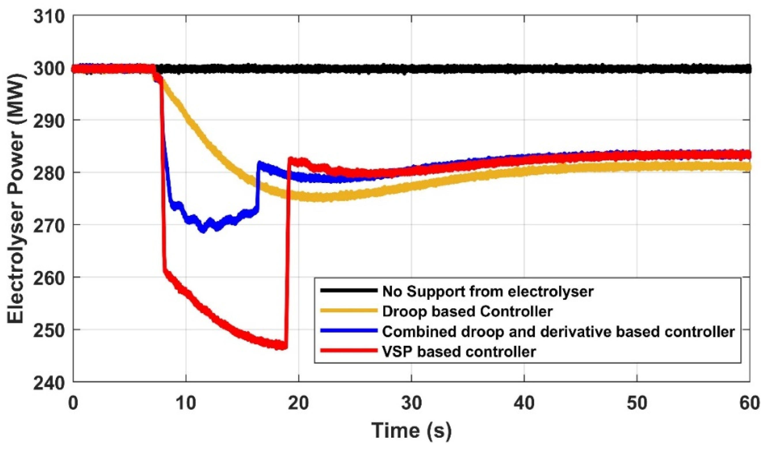
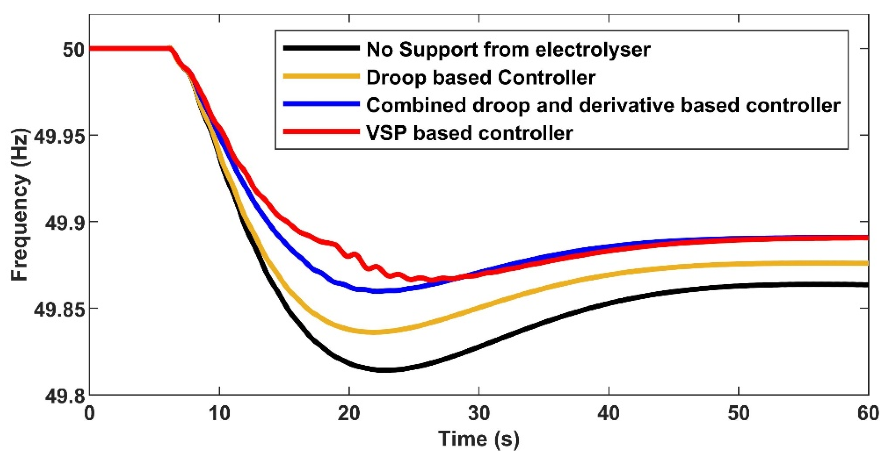
5.1. Frequency Support through FAPR Implemented in Electrolyzer

The electrolyzer present in the N3 network was modified with the inclusion of droop, combined droop derivative, and VSP-based FAPR. Therefore, during the active imbalance event, the FAPR controllers are expected to reduce the active power absorption accordingly. Figure 8 represents the active power variation of the electrolyzer and Figure 9 depicts the resulting frequency improvement due to the action of each FAPR strategy. As observed from the base plot in both figures (cf. black curves), the electrolyzer on its own does not regulate its power demand to mitigate the resulting under-frequency. However, due to action of the droop-based FAPR, taking into account the resulting frequency deviation, the power demand of the electrolyzer was proportionally reduced, resulting in an improvement of the frequency Nadir. On the other hand, the droop derivative FAPR helps in achieving a faster active power reduction. This improves RoCoF significantly, and also, as a by-product, even an improvement of the frequency Nadir is observed. The last controller implemented was the VSP-based FAPR controller. Here, the VSP-based FPR is not integrated with the BESS, since the electrolyzer is a load, and the power regulation is exclusively performed by reducing the electrolyzer’s active power demand. The output of VSP is directly given to the active power reference input, as in the case of droop and combined droop derivative controller. Additionally, please note that the droop controller is always active in combination with the derivative and VSP for the entire time. The time duration and active power reduction applied by the derivative and VSP controller are different.

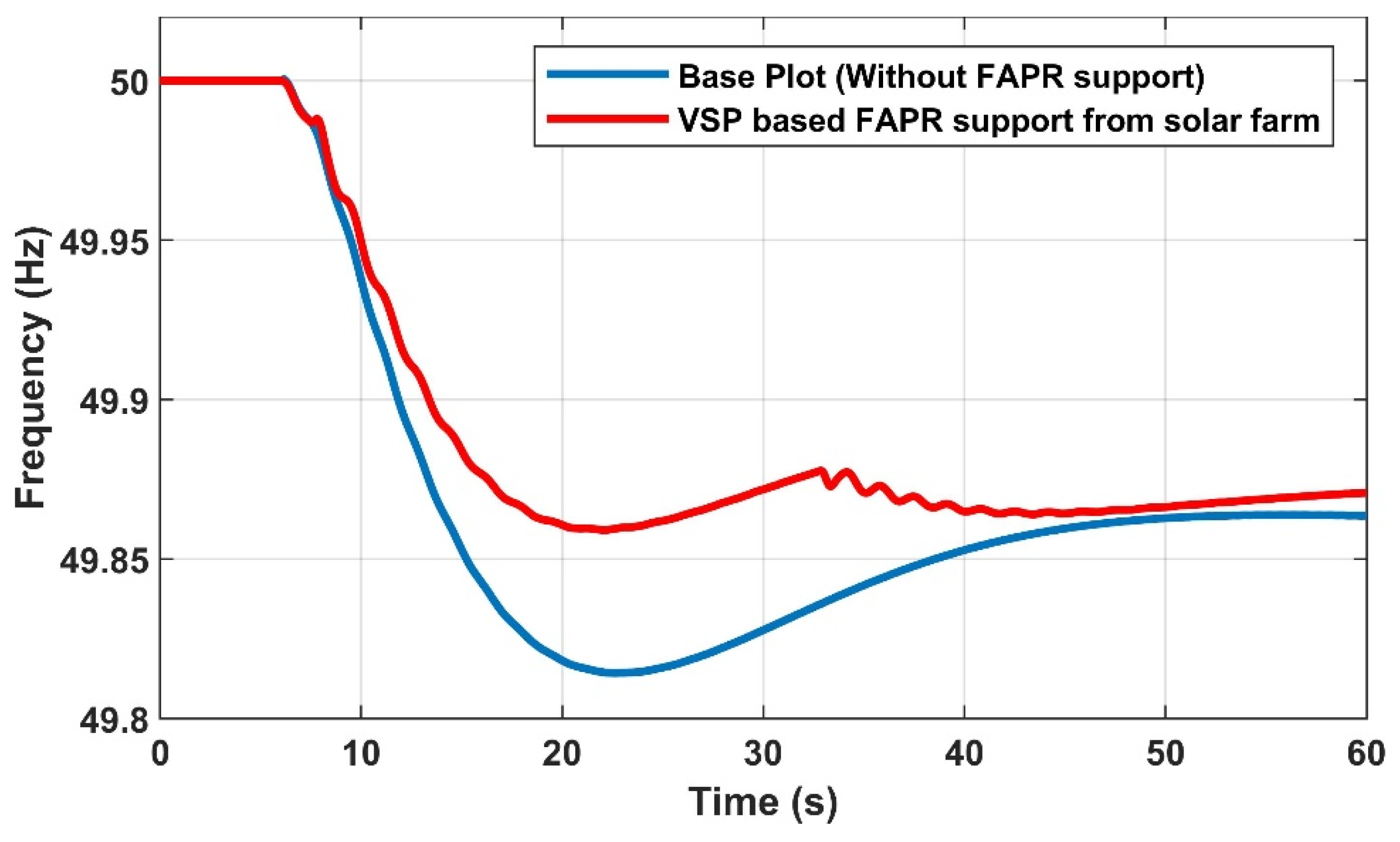
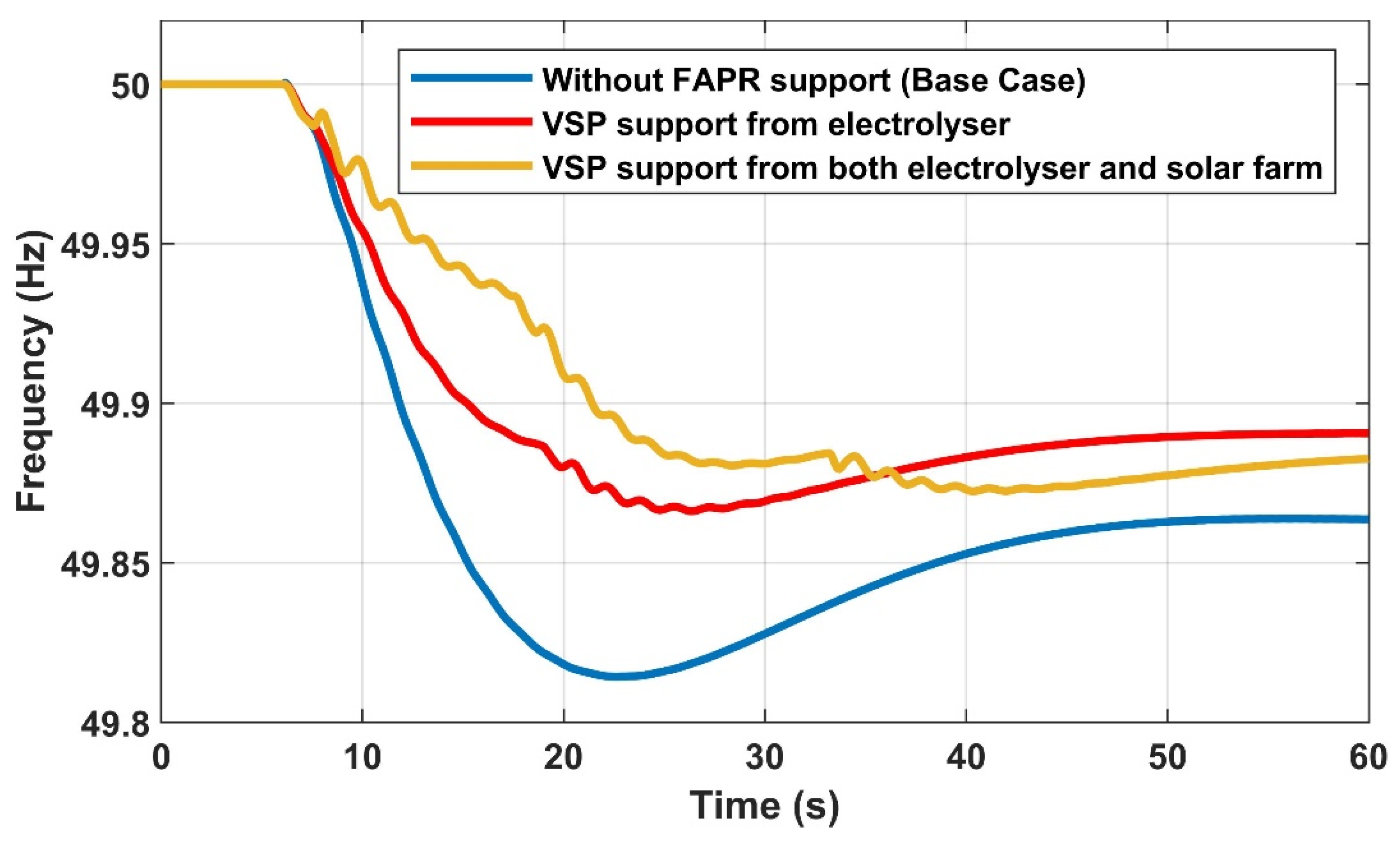
5.2. Frequency Support through VSP-Based FAPR Implemented in the Solar PV Farm

A 300 MW solar PV farm integrated with BESS and FAPR is taken into account. In this case, with a 200 MW sudden loss of Gemini wind generation, the solar PV farm provides support of a 10% increase in active power, i.e., 30 MW during 10 s. More support, in terms of higher active power injection and time of operation, is limited by the ratings of the BESS and grid-side converter. Figure 10 depicts the improvement in frequency due support of the solar PV farm.

5.3. Deployment of FAPR by the Different Controllable Sources within the Hub

Figure 11 shows that a higher degree of improvement in RoCoF and Nadir is achieved when FAPR acts in all controllable active power sources within the hub. Note also in Figure 11 that the frequency stabilizes at a relatively lower value when there is an uneven share of the fast active power adjustment. As shown in [12], this issue can be solved by performing an optimal and coordinated tuning of the FAPR strategies acting on the controllable devices. This aspect is also relevant for the design of an optimal transition between primary and secondary frequency control.

6. Conclusions

In this paper, the value of FAPR strategies for fast, active power–frequency support by renewable energy hubs was examined. Droop-based FAPR, droop derivative-based FAPR, and VSP-based FAPR were implemented and tested by performing a real-time EMT simulation on a hub comprising a solar PV farm and a PEM electrolyzer. The simulations conducted on a futuristic situation (year 2030) performed in a test system of the transmission network covering the north of the Netherlands showed that VSP-based FAPR is the most attractive option to quickly adjust the active power output of the solar PV farm and the PEM electrolyzer, resulting in the significant improvement of the RoCoF and the maximum frequency deviation. The simultaneous deployment of VSP-FAPR in each controllable active power source within the hub should be optimally tuned and coordinated to achieve a desired steady state of the frequency response after the occurrence of the maximum frequency deviation. Future studies shall investigate this aspect, as well as the design of an optimal transition between primary and secondary frequency control. The influence of emerging methods for data exchange and dynamic state estimation, e.g., [17,18], on the optimal deployment of FAPR shall also be investigated.

Author Contributions

Conceptualization, J.R.T., E.R., Z.A., N.V.K.; formal analysis, J.R.T., N.V.K., E.R., Z.A.; investigation, N.V.K., E.R., Z.A., J.R.T.; methodology, N.V.K., E.R., Z.A., J.R.T.; resources, N.V.K., J.R.T., E.A.; software, N.V.K., E.R., Z.A., J.R.T.; supervision, J.R.T., E.R., P.P. and M.v.d.M.; validation, N.V.K., E.R., J.R.T., Z.A.; visualization, J.R.T., E.R., Z.A. and N.V.K.; writing—original draft, N.V.K., J.R.T., E.R.; writing—review and editing, J.R.T., N.V.K., Z.A., E.R., P.P. and M.v.d.M. All authors have read and agreed to the published version of the manuscript.

Funding

This research work has received funding from the European Union’s Connecting Europe Facility (CEF) program under the grant agreement No INEA/CEF/SYN/A2016/1336043–TSO2020 Project (Electric “Transmission and Storage Options” along TEN-E and TEN-T corridors for 2020). This paper reflects only the authors’ views, and the European Commission is not responsible for any use that may be made of the information it contains. The APC was funded by Delft University of Technology.

Acknowledgments

This work has received funding from the European Union’s Connecting Europe Facility (CEF) program under the grant agreement No INEA/CEF/SYN/A2016/1336043–TSO2020 Project (Electric “Transmission and Storage Options” along TEN-E and TEN-T corridors for 2020). This paper reflects only the authors’ views, and the European Commission is not responsible for any use that may be made of the information it contains.

Conflicts of Interest

The authors declare no conflict of interest. The funders had no role in the design of the study; in the collection, analyses, or interpretation of data; in the writing of the manuscript, or in the decision to publish the results.

Nomenclature

RoCoFRate of Change of Frequency
BPMSBattery Power Management System
BESSBattery Energy Storage System
AGCAutomatic Generation Control

References

  1. Rakhshani, E.; Gusain, D.; Sewdien, V.; Torres, J.L.R.; van der Meijden, M.A.M.M. A Key Performance Indicator to Assess the Frequency Stability of Wind Generation Dominated Power System. IEEE Access 2019, 7, 130957–130969. [Google Scholar] [CrossRef]
  2. Kundur, P. Power System Stability and Control; McGraw-Hill: New York NY, USA, 1994. [Google Scholar]
  3. Hatziargyriou, N.; Milanovic, J.; Rahmann, C.; Ajjarapu, V.; Canizares, C.; Erlich, I.; Hill, D.; Hiskens, I.; Kamwa, I.; Pal, B.; et al. Definition and Classification of Power System Stability—Revisited & Extended. IEEE Trans. Power Syst. 2021, 36, 3271–3281. [Google Scholar] [CrossRef]
  4. Hong, Q.; Khan, M.A.U.; Henderson, C.; Egea-Àlvarez, A.; Tzelepis, D.; Booth, C. Addressing Frequency Control Challenges in Future Low-Inertia Power Systems: A Great Britain Perspective. Engineering 2021, in press. [Google Scholar] [CrossRef]
  5. Rakhshani, E.; Perilla, A.; Veerakumar, N.; Ahmad, Z.; Torres, J.L.R.; van der Meijden, M.A.M.M. Analysis and tuning methodology of fapi controllers for maximising the share of grid-connected wind generations. IET Renew. Power Gener. 2020, 14, 3816–3823. [Google Scholar] [CrossRef]
  6. Sanchez, F.; Gonzalez-Longatt, F.; Torres, J.L.R. Multi-objective optimal provision of fast frequency response from EV clusters. IET Gener. Transm. Distrib. 2020, 14, 5580–5587. [Google Scholar] [CrossRef]
  7. Rakhshani, E.; Rouzbehi, K.; Sánchez, A.J.; Tobar, A.C.; Pouresmaeil, E. Integration of Large Scale PV-Based Generation into Power Systems: A Survey. Energy 2019, 12, 1425. [Google Scholar] [CrossRef] [Green Version]
  8. Low, F.; Power, I.; Using, S.; Technique, C. Primary Frequency Response Enhancement for Future Low Inertia Power Systems Using Hybrid Control Technique. Energies 2018, 11, 699. [Google Scholar] [CrossRef] [Green Version]
  9. Rakhshani, E.; Remon, D.; Rodriguez, P. Effects of PLL and Frequency Measurements on LFC Problem in Multi-Area HVDC Interconnected Systems. Int. J. Electr. Power Energy. Syst. 2016, 81, 140–152. [Google Scholar] [CrossRef]
  10. Tuinema, B.W.; Adabi, E.; Ayivor, P.K.S.; Suárez, V.G.; Liu, L.; Perilla, A.; Ahmad, Z.; Torres, J.L.R.; van der Meijden, M.A.M.M.; Palensky, P. Modelling of large-sized electrolysers for real-time simulation and study of the possibility of frequency support by electrolysers. IET Gener. Transm. Distrib. 2020, 14, 1985–1992. [Google Scholar] [CrossRef]
  11. Dreidy, M.; Mokhlis, H.; Mekhilef, S. Inertia response and frequency control techniques for renewable energy sources: A review. Renew. Sustain. Energy Rev. 2017, 69, 144. [Google Scholar] [CrossRef]
  12. Zhang, C.; Rakhshani, E.; Veerakumar, N.; Torres, J.L.R.; Palensky, P. Modeling and Optimal Tuning of Hybrid ESS Supporting Fast Active Power Regulation of Fully Decoupled Wind Power Generators. IEEE Access 2021, 9, 46409–46421. [Google Scholar] [CrossRef]
  13. Torres, J.L.R.; Tuinema, B.W.; Adabi, M.E.; Ahmad, Z.; Suárez, V.G.; Ayivor, P.K.S.; Kumar, N.V.; Liu, L.; Perilla, A.; Alshehri, F.A.; et al. TSO2020 Activity 2—Final Report: Stability Analysis of an International Electricity System connected to Regional and Local Sustainable Gas Systems; TSO2020 Project (Electric “Transmission and Storage Options” along TEN-E and TEN-T Corridors for 2020); December 2019. Available online: http://tso2020.eu/wp-content/uploads/2020/01/TSO2020_Final_Report_TUD.pdf (accessed on 11 July 2021).
  14. Veerakumar, N.; Ahmad, Z.; Adabi, M.E.; Torres, J.R.; Palensky, P.; van der Meijden, M.; Gonzalez-Longatt, F. Fast Active Power-Frequency Support Methods by Large Scale Electrolyzers for Multi-Energy Systems. In Proceedings of the 2020 IEEE PES Innovative Smart Grid Technologies Europe (ISGT-Europe), The Hague, The Netherlands, 26–28 October 2020; pp. 151–155. [Google Scholar] [CrossRef]
  15. Torres, J.L.R.; Ahmad, Z.; Kumar, N.V.; Rakhshani, E.; Adabi, E.; Palensky, P.; van der Meijden, M.A.M.M. Power Hardware-in-the-Loop-Based Performance Analysis of Different Converter Controllers for Fast Active Power Regulation in Low-Inertia Power Systems. Energies 2021, 14, 3274. [Google Scholar] [CrossRef]
  16. Robert, C. Review of International Grid Codes; Lawrence Berkeley National Laboratory: Berkeley, CA, USA, 2018. [Google Scholar]
  17. Noor-A-Rahim, M.; Khyam, M.O.; Li, X.; Pesch, D. Sensor Fusion and State Estimation of IoT Enabled Wind Energy Conversion System. Sensors 2019, 19, 1566. [Google Scholar] [CrossRef] [PubMed] [Green Version]
  18. Enescu, F.M.; Ionescu, V.M.; Marinescu, C.N.; Ştirbu, C. System for monitoring and controlling renewable energy sources. In Proceedings of the 2017 9th International Conference on Electronics, Computers and Artificial Intelligence (ECAI), Targoviste, Romania, 29 June–1 July 2017; pp. 1–6. [Google Scholar] [CrossRef]
Figure 1. Example power flow profile of the N3 test system for year 2030 [13].
Electronics 10 01651 g001
Figure 2. Connection of the inverter interfaced 300 MW PEM electrolyzer [14].
Electronics 10 01651 g002
Figure 3. Layout of the Type-4 renewable generators belonging to the renewable energy hub [15].
Electronics 10 01651 g003
Figure 4. Screenshot of the RSCAD implementation of a renewable energy hub, including a solar farm and a PEM electrolyzer, with a theoretical expansion to include a Type-4 wind turbine [13].
Electronics 10 01651 g004
Figure 5. Schematic of the droop-based FAPR.
Electronics 10 01651 g005
Figure 6. Schematic of the droop derivative-based FAPR.
Electronics 10 01651 g006
Figure 7. Schematic of the VSP-based FAPR.
Electronics 10 01651 g007
Figure 8. Shape of the power output of the PEM electrolyzer due to the action of FAPR.
Electronics 10 01651 g008
Figure 9. Shape of the system frequency response due to the action of FAPR on the PEM electrolyzer.
Electronics 10 01651 g009
Figure 10. Frequency response due to the support of a solar PV farm with VSP-based FAPR.
Electronics 10 01651 g010
Figure 11. Frequency comparison plots in renewable energy system conclusions.
Electronics 10 01651 g011
Table 1. Active power share in the N3 test system for year 2030.
Generator/HVDC LinkYear 2030 Scenario
GEMINI Wind farm (EOS)450 MW
NorNed Connection (EEM)700 MW
COBRAcable Connection (EOS)−700 MW
GEN1 (EOS)3 × 430 MW
GEN2 (EOS)2 × 430 MW
GEN3 (EOS)233 MW
Total3490 MW
Publisher’s Note: MDPI stays neutral with regard to jurisdictional claims in published maps and institutional affiliations.

