Article

Stability Improvement of Dynamic EV Wireless Charging System with Receiver-Side Control Considering Coupling Disturbance

1
College of Mechatronics and Control Engineering, Shenzhen University, Shenzhen 518060, China
2
Department of Electrical Engineering, The Hong Kong Polytechnic University, Hong Kong 999077, China
*
Author to whom correspondence should be addressed.
Electronics 2021, 10(14), 1639; https://doi.org/10.3390/electronics10141639
Submission received: 20 May 2021 / Revised: 2 July 2021 / Accepted: 2 July 2021 / Published: 9 July 2021
(This article belongs to the Special Issue Emerging Technologies in Wireless Power Transfer Systems)

Abstract

:
Receiver-side control has been a reliable practice for regulating the transferred energy to the batteries in the electric vehicle (EV) wireless power transfer (WPT) systems. Nonetheless, the unpredictable fluctuation of the mutual inductance in dynamic wireless charging brings extreme instability to the charging process. This overshoot that appears in instant vibrations may largely increase the voltage/current stress of the system, and even cause catastrophic failure in the battery load. In addition, the speed of the vehicles may lead to untraceable steady-state operation. However, existing solutions to the above two issues suffer from either long communication time delay or significantly compromised output regulation. In this paper, the slow dynamics and the overshoot issues of the WPT system are elaborated in theory, and the small-signal model mainly considering mutual inductance disturbance is established. A simple feedforward control is proposed for overshoot damping and fast system dynamics. Experimental results validate that the overshoot can be reduced by 13% and the settling time is improved by 50% in vehicle braking or acceleration. In constant speed driving, the battery charging ripple is decreased by 12% and ensures better system stability.

1. Introduction

The commitment to achieving carbon neutrality by over 40 major economic entities during the next few decades will accelerate the development of electric vehicles (EVs) around the world [1]. However, extensive cabled charging holds back the consumers with inconvenience to plug in and plug out daily and causing potential dangers in electric connectors [2]. Moreover, the park-and-charge manner in wired charging induces transportation blockage, especially in rush hours [3]. To address this issue, wireless power transfer (WPT) technology is proposed as an alternative solution for the battery charging of EVs. Research activities of WPT for EVs are intensified over the last three decades [4,5,6,7,8,9,10,11]. Despite this, although the Society of Automotive Engineers (SAE) has released J2954 as a standard for EV wireless chargers [12], so far, only a handful of power companies and organizations have deployed wireless battery charging systems for EVs [13,14,15]. One of the reasons is that the stability of the conventional WPT system using series (SS) compensation with a user-side buck converter cannot be guaranteed, and the dynamic performance is unsatisfactory, which may damage the battery load and power supply [16]. Researchers have also reported similar problems with WPT applications in consumer electronics and mid-power devices [17,18,19]. Therefore, the fluctuation of the mutual inductance during dynamic charging becomes the most worthy of consideration.
Some studies have discussed that the optimized shape of the coupler can improve the tolerance of misalignment during the movement of the secondary side [20,21,22]. The article [19] proposes a split flat solenoid coupler to improve the robustness of mutual inductance under misalignment. Taking into account the separation distance between the primary side ferrites, the optimized transmitter structure can increase the lateral mutual inductance tolerance by nearly 20%. However, in the case studies, an approximately 13% coupling coefficient reduction can be observed when the displacement is 50% in size ratio. The same conclusion can be obtained in [21,22], even though the new structures and optimization methods are proposed. Hence, the DC-DC converter on the receiving side is an urgent demand in the load side system for output energy regulation.
Several user-end control methods have been proposed, which can be classified into “Communication-based” and “Communication-free” manners [17,23,24,25,26,27,28,29,30]. These methods are usually designed for primary-side inverters only, or both for front-end inverters and user-side buck converters. “Communication-based” scheme refers to the method where the output information is transferred to a primary inverter controller with out-of-band communication (i.e., Bluetooth) or in-band communication (i.e., frequency-shift-keying). In [25], a two-way control method is proposed to track the maximum system efficiency under variable load conditions, in which in-band load shift keying (LSK) is implemented through low-power backtesting. However, for the proposed system, there is no precise mathematical model, and the load is only equivalent to a pure resistance without considering capacitance. By integrating a buck–boost converter to adjust the output power, reference [26] proposes a dynamic WPT system with Bluetooth communication. Despite the precise coupling estimation, the method highly relies on the real-time model, thus it loses the superiority in battery charging for EVs as the battery condition shifts. “Communication-free” control method has higher reliability and fast system monitoring response due to the absence of the surrounding electromagnetic field influence and dual communication. In [27], a half-bridge buck converter is used to regulate the energy transfer to a hybrid energy storage system. Nevertheless, this study does not attempt to verify the interference situation. References [28,29] illustrate the unified power control in dynamic charging of electric vehicles. The energy is controlled by a buck converter connected to the secondary side rectifier, and both cover only speed or voltage input interference. Literature [30] proposed a more practical dynamic wireless charging technology for electric vehicles based on model predictive control (MPC). Although the system has a fast response to speed changes and coupling changes, the mathematical model of the system is inconsistent with the mathematical model of the EV battery, and the output current cannot always remain the same. Although the overshoot problem is mentioned in these papers, the theoretical analysis is based on a resistive load that inevitably leads to a decrease in control performance.
Although the modeling of the WPT system in the above-mentioned literature is involved, the disturbance of mutual inductance is not considered in the theoretical analysis. In consequence, a user-end control method where a feedforward path is employed to the half-bridge buck converter. The coupling fluctuation in a different driving manner in the WPT system and its modelling are established in this paper. The additional feedforward loop enables a larger phase margin and lower crossover frequency, so that the system dynamic and stability can be improved without a real resistor that may influence the efficiency.

2. Model of SS-Compensated WPT Systems and Dynamic Issues Illustration

2.1. SS-Compensated Wireless Charging System with Receiver-Side Buck Converter

A typical series–series (SS)-compensated WPT system with a user-end half-bridge buck converter is depicted in Figure 1a. A full-bridge inverter that is powered by a DC voltage source V i n consists of 4 metal-oxide-semiconductor field-effect transistors (MOSFETs). The inductance of the transmitter coil L p is compensated by a series capacitor C p , and the equivalent-series-resistance (ESR) of the transmitter resonator, including the copper and components resistance, is denoted as R p . Similarly, the receiver coil inductance Ls is compensated by a series-connected capacitor C s and the ESR of the receiver coupler is Rs. The inverter generates high-frequency AC power which is delivered to the receiver via a mutual inductance of M . The received AC energy is rectified by a passive rectifier that consists of 4 diodes, and then filtered by a capacitor C d c . Hence, the input voltage of the half-bridge converter (i.e., V d c ) is a DC voltage such that the buck converter can step down the voltage to charge the battery load via the two active switches (i.e., S b 1 and S b 2 ). The sketchy waveforms of the main parameters of the conventional WPT system are depicted in Figure 1b. A small deadtime (i.e., α T s / 2 π ) is determined for the inverter to avoid short circuits. The leakage inductance of the transmitter coil is compensated to be a little bit greater than the operating frequency to achieve soft-switching, such that the transmitter current (i.e., i p ) is leading the input voltage v p . The output voltage of the receiver resonator (i.e., v s ) and receiver current (i.e., i s ) are in phase. Here, the amplitude of v s equals to the addition of the input voltage of the buck converter (i.e., V d c ) and forward-voltages of two diodes (i.e., V D ). The output current of the rectifier (i.e., i d c ) comprises a DC component I o and a high-frequency AC component i C d c . The AC energy is filtered by the capacitor C d c such that only the DC component is fed into the buck converter when the switch S b 1 is turned on and the switch S b 2 is turned off. By assuming the duty ratio of the buck converter is d, the average value of the DC component can be calculated based on
I ¯ o = d I ¯ L o
where I ¯ L o is the average value of I L o . It is noted that the ripples of I L o can be filtered by the capacitor C o . Thus, I ¯ L o equals to the battery charging current as
I ¯ L o = I bat
According to the circuit diagram and waveforms in Figure 1, the complete dynamic model of the conventional SS compensation WPT system can be established by modeling the resonant conversion and the step-down conversion respectively. The resonant conversion part is modeled based on the general unified dynamic phasor (GUDP) technology [31], and the step-down conversion part is modeled based on the state space averaging (SSA) technology [32]. It should be noted that the construction of the dynamic model is based on two common facts, that is, the quality factor of the coil is high and the deadtime of the inverter is short. Therefore, only the basic components need to be considered for the resonator.
By employing GUDP technology on the general M-model of the resonator at the resonant frequency [33], a dynamic model of resonant conversion can be obtained based on the equivalent circuit shown in Figure 1b as,
2 L p I ˙ p = R p I p ω M I s + V p 2 L s I ˙ s = ω M I p R s I s V s
where I p , I s , V p , and V s are the amplitudes of the fundamental components i p , i s , v p , and v s , respectively. Based on Fourier analysis, the voltage amplitudes (i.e., V p and V s ) can be calculated as,
V p = 4 π V i n cos α 2
V s = 4 π V d c + 2 V D
where VD is the forward voltage of the diodes. By substituting (4) and (5) into (3),
I ˙ p = R p 2 L p I p ω M 2 L p I s + 2 cos α 2 π L p V i n I ˙ s = ω M 2 L s I p R s 2 L s I s 2 π L s V d c + 2 V D
By using the SSA technique, the total buck converter model can be expressed as
C d c V ˙ d c = i ¯ d c d I ¯ L o L o I ¯ ˙ Lo = d V d c R o I ¯ L o I bat r bat V bat
where i ¯ d c is the average value of i d c and rbat is the internal resistance of the battery load. According to the Fourier analysis,
i ¯ d c = 2 π I s
By substituting (2) and (8) into (7),
V ˙ d c = 1 C d c d I bat + 2 π C d c I s I ˙ L o = 1 L o d V d c R o + r b a t L o I L o 1 L o V b a t
By considering both (6) and (9), the complete model of the conventional SS-compensated WPT system can be expressed as
I ˙ p = R p 2 L p I p ω M 2 L p I s + 2 cos α 2 π L p V i n I ˙ s = ω M 2 L s I p R s 2 L s I s 2 π L s V d c + 2 V D V ˙ d c = 2 π C d c I s 1 C d c d I bat I ˙ bat = 1 L o d V d c R o + r bat L o I bat 1 L o V bat
It can be seen from (10) that a vibration of the mutual inductance M of the WPT system (i.e., V d c ) can induce a dynamic variation of the battery charging current (i.e., I b a t ).

2.2. Coupling Issues in Constant Speed Driving and Braking/Acceleration

The illustration of the EV dynamic charging is depicted in Figure 2. The primary side is designed based on multiple transmitters structure. The transmitters (TXs) have various degrees of coupling coefficient with the receiver (RX) pre-installed in the vehicle chassis. By labeling the mutual inductance between the specific transmitter TXn and receiver RX as Mn, the total coupled inductance,
M = n = 0 M n
Hence, regardless of the vertical vibration, M can be sinusoidally fluctuated by supposing the vehicle is moving at a constant speed based on the model analysis in [34]. While in slam braking and acceleration, the mutual inductance will instantly be increased or decreased. The sketchy waveforms of the receiver side circuit in both cases are shown in Figure 3. According to the WPT standard proposed by SAE, the operation frequency is regulated as 85 kHz. This frequency is far larger than the mutual disturbance frequency, even the vehicle drives at high speed. Hence, the fluctuation of mutual inductance can be considered as a low-frequency disturbance injected into the receiver side buck converter.
According to (10), the small-signal model for the buck converter is,
V ˜ ˙ d c = 1 C d c d ¯ I ˜ b a t + I ¯ b a t d ˜ + 2 π C d c I ˜ s I ˜ ˙ b a t = 1 L o d ¯ V ˜ d c + V ¯ d c d ˜ R o + r bat L o I ˜ b a t
where X ¯ and X ˜ represent the steady-state value and small-signal variation of x (x = V d c , I b a t , d , or I s ), respectively.
In order to identify M, the Laplace transform of (6) is found as follows,
2 L p s + R p 2 L s s + R s + ω 2 M 2 I p s = 4 π ω M cos α 2 V i n 4 π 2 L p s + R p V d c + 2 V D 2 L p s + R p 2 L s s + R s + ω 2 M 2 I s s = 4 π ω M V d c + 2 V D + 4 π cos α 2 2 L s s + R s V i n
At low frequency, Equation (13) can be further simplified as,
I p s = 4 π ω M V d c + 2 V D I s s = 4 π ω M cos α 2 V i n
on the assumption that 2 L p s + R p < < ω M and 2 L s s + R s < < ω M . Equation (14) suggests that the profiles of I p and I s resemble those of V d c and V i n , respectively, with only a difference in the gains. Thus, it can be inferred that the response of i p to a change of V d c resembles the response of V i n to a change of I s . The latter is simpler and thus is discussed below, since studying the buck converter will suffice. As a common practice in literature [5], a PI compensator is utilized for the buck converter, i.e.,
d = 1 k p I b a t I r e f + k i I b a t I r e f d t
And the relationship between the small signal of mutual inductance and secondary side current can be found as,
I s = i ¯ s M ¯ M ˜
By substituting (14), (15) and (16) into (12), the transfer function for the response of I b a t to M ,
G M I b a t = 2 d ¯ I ¯ s s π M ¯ L o C d c s 3 + C d c R o + r bat V ¯ d c k p s 2 d ¯ 2 + d ¯ I ¯ b a t k p V ¯ d c k i s + d ¯ I ¯ b a t k i
The battery charging current is regulated by a closed-loop proportional–integral (PI) controller via adjusting the duty ratio of the half-bridge buck converter. Figure 4a,b are the bode diagram and pole-zero plot for G M I b a t s with a constant k i = 0.1 and various k p by using the parameters in Table 1. In the WPT coils, the switching frequency f follows the SAE J2954 standard for EV wireless charging. The coil is circularly stranded in the radius of 100 mm, and the number of turns N is 15. Under the constrain of SAE J2954, the ferrites are applied to guide the magnetic flux, and the electromagnetic field is shield by the aluminum plates. The self-inductance ( L p and L s ), resistance ( R p and R s ) and mutual inductance ( M ) is measured from the experiment platform, which has a two 300 mm * 150 mm coupler and 50 mm air gap. The capacitance compensates the self-inductance L by following C = 1 / L 2 π f 2 . For the buck converter, the L o and C o are used for stabilizing the charging current and voltage for batteries. The parameters of the L o and C o are selected to be large enough for absorbing the ac components. The output resistor R o helps to avoid over-current, and its value is selected to feed the charging current 1.62 A to the battery pack when the duty ratio of the half-bridge inverter is 0.5. It can be observed from Figure 4a that the response of I b a t to coupling disturbance in low frequency can be slightly suppressed by increased k p . However, the overshoot restraint is limited even a large k p is employed, and the system dynamics are not further improved. The system stability can be seen in Figure 4b. The dominant pole moves farther when the k p is raised, and a shorter settling time is achieved. If k p > 0.3 , there will be a vibration in I b a t that will cause detrimental system dynamics, and rising k p excessively will even cause instability. Therefore, a more effective method is needed to suppress the overshoot and enhance system dynamic performance.

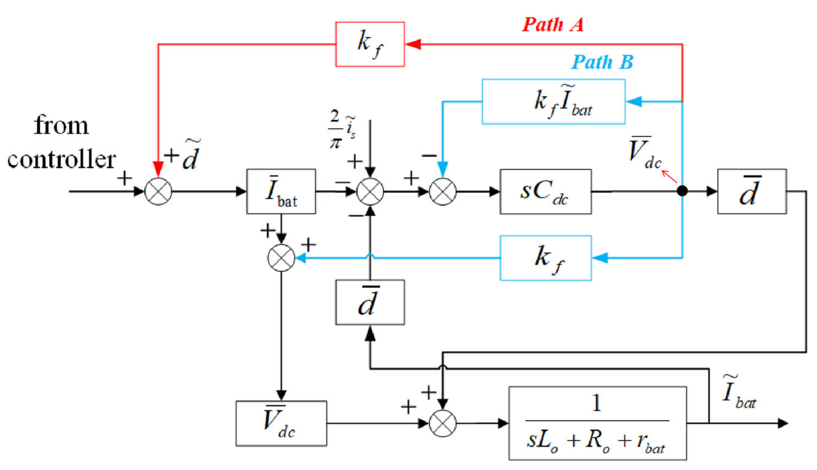
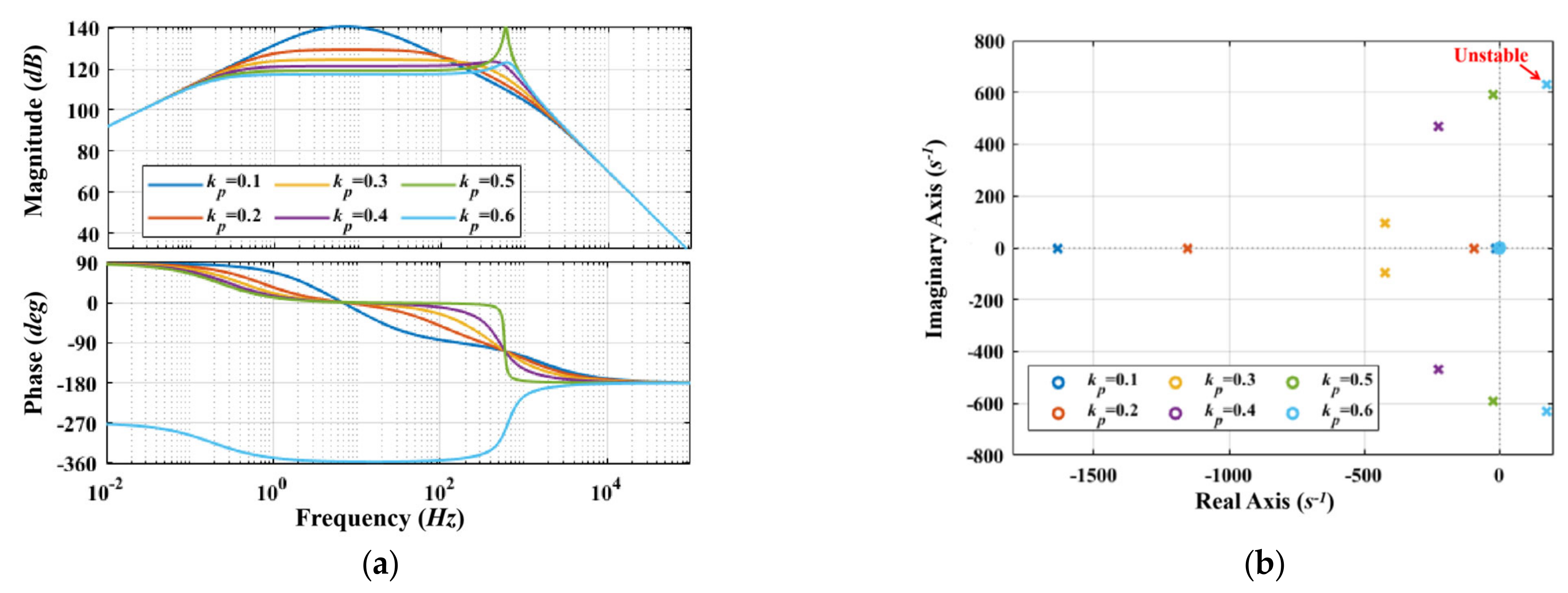
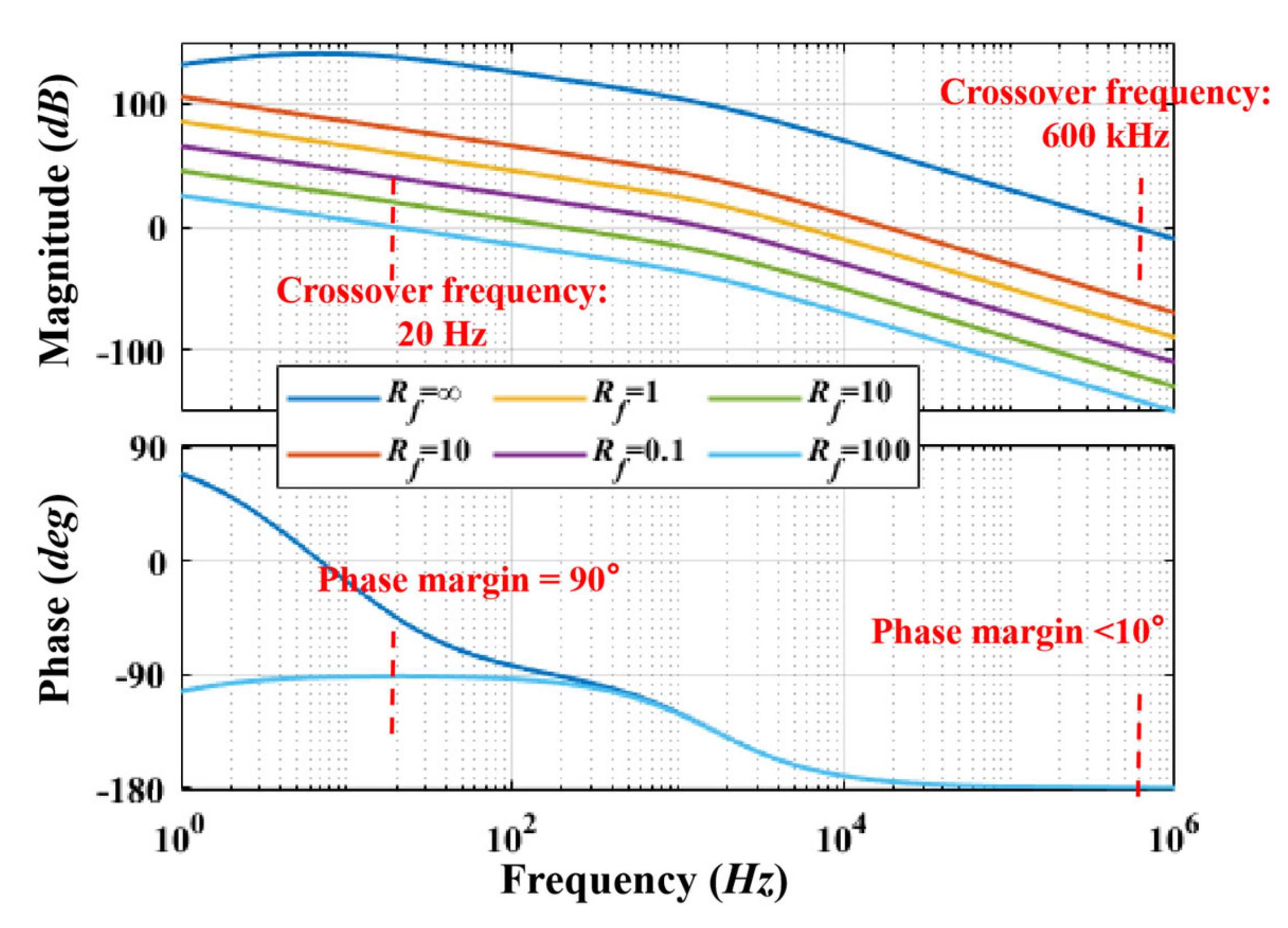
3. Overshoot Damping and Feedforward Control

As stated in the previous section, a sinusoidal fluctuation or step change of M will excite an obvious overshoot of I b a t . To suppress this overshoot, a solution is proposed via receiver-side control design, which increases the damping in the WPT system.
As shown in Figure 5, by Supposing that a parallel resistor R f is connected in parallel with C d c , the state equation of Ibat becomes
C d c d V ˜ d c d t = 2 π i ¯ s M ¯ M ˜ d ¯ I ˜ b a t + I ¯ b a t d ˜ V ˜ d c R f
The transfer function of the system with the proposed feedforward loop,
G M I b a t ' = 2 s d ¯ i ¯ s π M ¯ s C d c + R d a m p s 2 L o + s R o + r b a t k p V ¯ d c k i V ¯ d c d ¯ 2 s + d ¯ I ¯ b a t s k p + k i
The comparison of schemes with different damping resistance R f is illustrated in Figure 6. Notably, the scenario with no parallel resistor is marked as R f = in this figure. It is apparent that the low-frequency gain of G M I b a t ' s can be largely suppressed by reducing R f . Furthermore, the phase margin is improved from less than 10 ° to 90 ° with the proposed circuit, and thus the system stability is highly sustained.
In practice, using a real resistor R f will inevitably affect the total efficiency of the transmission. The substitution of this scheme is emulating it with a feedforward loop of V d c . Figure 7 shows the block diagram of the buck converter with a feedforward loop in a small-signal model and disturbance, where k f is the feedforward gain. The feedforward path of V d c can be equivalent to Path A and Path B. It is worth mentioning that Path A has the same effect as the parallel damping resistor R f , which is named damping factor k f and is as follows,
k f = 1 R f I ¯ b a t
The circuit diagram that contains the feedforward loop and PI controller for CC/CV implementation is demonstrated in Figure 8. Equation (18) refers to the current source nature of the rectified AC power. The PI parameters for CC and CV are slightly different. The CC mode charging is selected when the battery voltage V b a t is lower than the maximum charging voltage, otherwise, the CV mode is chosen. The voltage of the filter capacitor C o is sensed and multiplied by the feedforward gain. The feedforward loop output is together with the PI controller, and then the duty ratio of the half-bridge driver is determined by this sum.

4. Experimental Results

The experiment platform is shown in Figure 9, where all components and measurement equipments are depicted. In order to verify the validation and effectiveness of the proposed method, the WPT experiment platform is constructed on 85 kHz operation frequency. The Li-ion battery pack used by several entities, such as Tesla, consists of 100 series-connected Panasonic NCR18650B batteries. The basic design of the battery pack is inherited in this experiment, where make the Li-ion batteries are series-connected, although the number of NCR18650B is not as much as the actual vehicle battery pack for lab constraints. With different numbers of batteries, the characteristics of the charging (i.e., charging/discharging rate, response time, etc.) are the same, and thus the effectiveness of the proposed control method is not influenced by the output power level. In CC mode, the nominal battery current I b a t is 1.6 A. In CV mode, the nominal battery voltage V b a t is 16 V where 4 NRC18650B are series-connected and used as the load battery for EVs. The feedforward gain k f of V d c is consistently designed as 0.06. The identical PI gains are applied in all cases, i.e., kp = 0.1, ki = 0.1, for eliminating vibration in response to coupling disturbance based on Figure 4. The components parameters and the type of Digital Signal Processing (DSP) that are utilized in the design are listed in Table 2. Figure 7 shows the photo of the experimental prototype. The waveforms are measured with an HDO4024A oscilloscope, 2 N2873 passive voltage probes, an N2790A differential voltage probes, and two 80i-110s current probes.

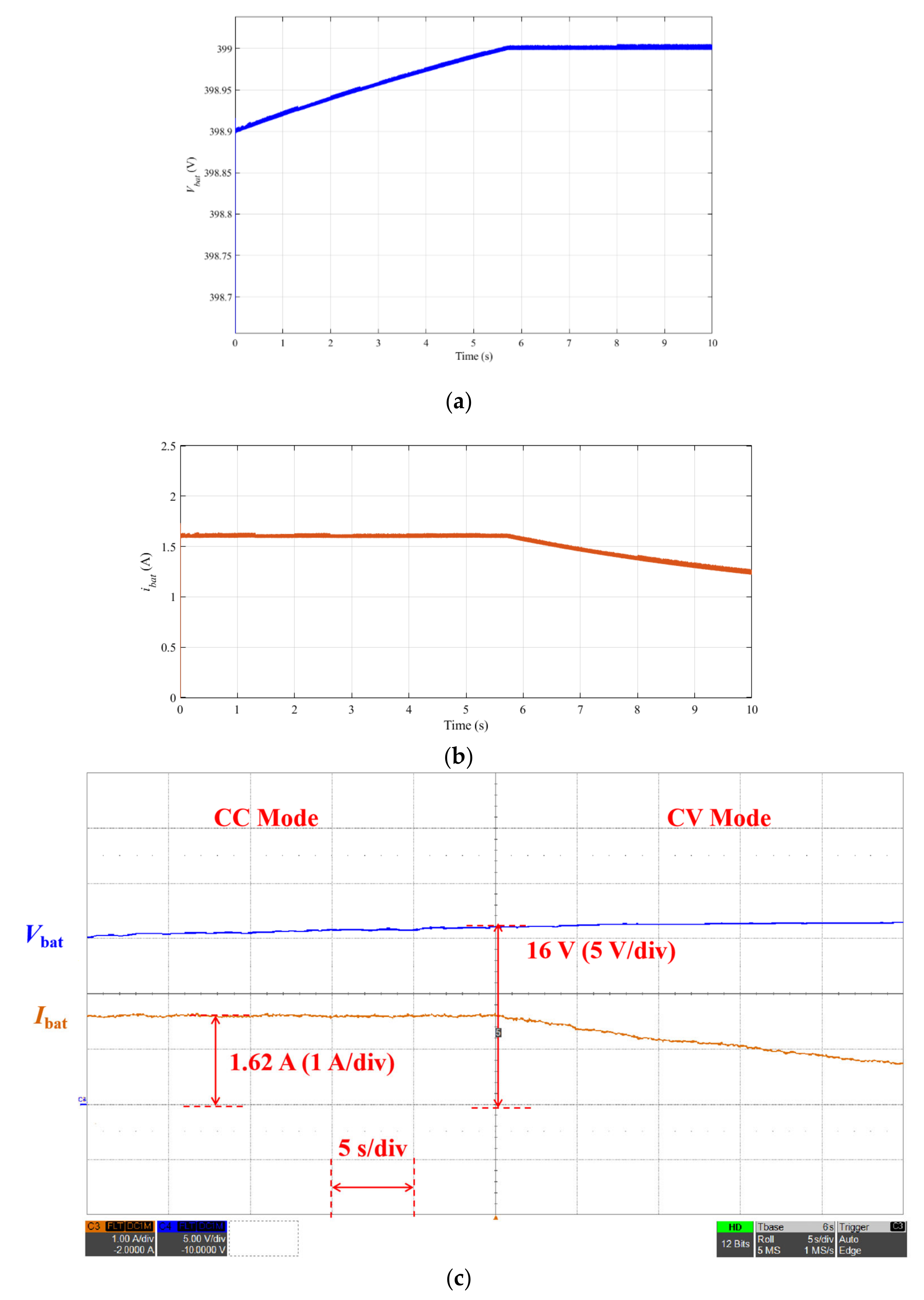
4.1. CC/CV Implementation

Figure 10 demonstrates the shift moment from CC mode to CV mode in simulation and experiment, where V b a t and I b a t are drawn as blue and orange curves, respectively. In the simulation, the CC/CV mode shifting criteria is the battery voltage (i.e., V b a t ) is higher than 399 V, which is slightly lower than the nominal voltage 400 V. Due to the lab constraints, the experiment is implemented in a scaled-down platform. In CC mode, I b a t is controlled and sustained at 1.62 A, and V b a t increases gradually. While in CV mode, the battery current decreases slowly, and the voltage has a slight raise but it is nearly a constant. Therefore, both constant current and voltage modes are achieved in this study. As the time scale is 5 s/div, the CC mode takes more time in the whole charging process. Moreover, the duty ratio of the buck converter decreased to zero in CV mode, and the disturbance from the WPT system cannot influence the battery. Hence, only CC mode is worth investigating in this study.

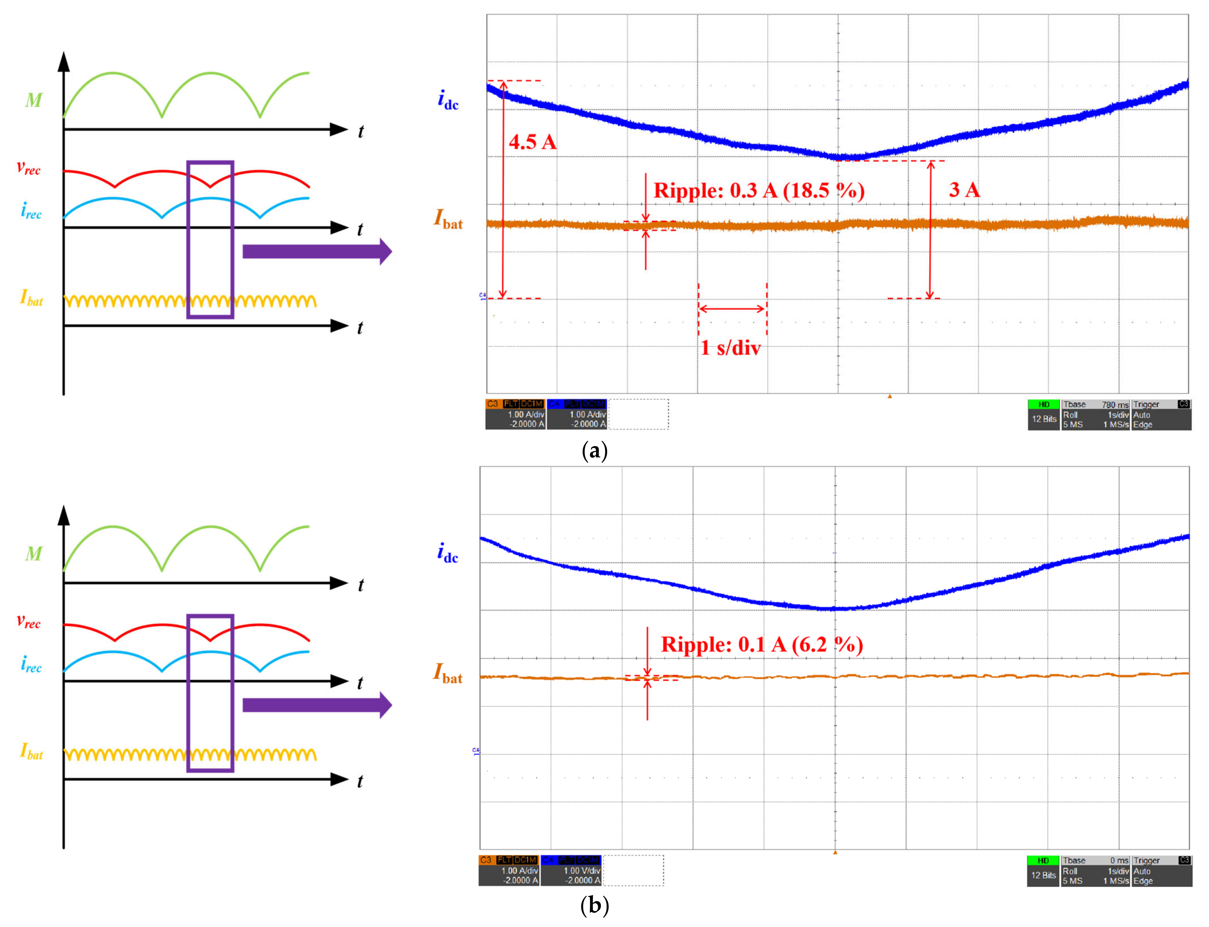
4.2. Constant Speed Driving—Sinusoidal Disturbance

According to Equation (14), a sinusoidal voltage input is allowed to be applied for imitating the coupling disturbance in constant speed driving. In Figure 11, V i n decreases from 25 V to 20 V, which is equal to the change that the mutual inductance drops slowly from 20 μH to 13 μH.
In Figure 11a, i d c gradually drops from 4.5 A to 3 A, and there is a 0.3 A ripple current in the waveform of I b a t . By using the feedforward loop, it can be seen from Figure 11b that the ripple of I b a t is abbreviated from 0.3 A to 0.1 A. Although the disturbance of the coupling coefficient is not practically verified in this paper, due to the experiment space constraints, the experimental results prove that the proposed control scheme contributes to less battery charging current fluctuation in a continuous change of mutual inductance.

4.3. Braking/Acceleration Driving—Step Disturbance

In Figure 12, the mutual inductance between the transmitter and the receiver increases from 20 μH to 25 μH instantaneously.
In Figure 12a, I b a t has instantaneous increase from 1.62 A to 2.28 A, and the result confirms the theoretical analysis of the overshoot issue in Figure 3b. Conversely, in Figure 12b, V L p and V L s become nearly a monotonic and their overshoots are effectively suppressed owing to the feedforward of V d c . The settling time of I b a t is substantially shortened from 151 ms to 51 ms, and the overshoot of it is decreased from 40.7% in Figure 12a to 27.7% in Figure 12b. Hence, the results prove that the overshoot issue is damped and faster system dynamics are achieved.

5. Conclusions

The mutual inductance fluctuations in the EV dynamic WPT system are mainly investigated in this study, including sinusoidal disturbance in constant speed driving and step change in braking/acceleration. The small-signal model considering the coupling vibration is constructed, and the necessity of employing a feedforward loop is elaborated. The experimental results show that the ripple of battery charging current in constant speed driving is decreased from 18.5 to 6.2%. In the step-change case, the overshoot is damped by 13% and the settling time is halved from 151 ms to 49 ms. The experiments verify the stability improvement and fast system response by utilizing the feedforward of V d c . As can be seen in the comparison of the performance listed in Table 3, this paper focuses on the actual coupling disturbance issues in EV driving with battery-based analysis. The settling time is comparably fast, and the overshoot issue is largely solved. The system is designed without any communication between transmitters and receivers, which improves reliability and cuts down the cost.

Author Contributions

Conceptualization, K.C. and Y.Y.; methodology, K.C. and J.P.; software, K.C.; validation, K.C., J.P. and K.W.E.C.; formal analysis, K.C.; investigation, K.C.; resources, K.C.; data curation, K.C. and Y.Y.; writing—original draft preparation, K.C.; writing—review and editing, J.P.; visualization, Y.Y.; supervision, J.P.; project administration, J.P.; funding acquisition, J.P. and K.W.E.C. All authors have read and agreed to the published version of the manuscript.

Funding

This research was funded partly by The National Natural Science Foundation of China under grant U1913214, International Cooperation Program of Shenzhen Government (GJHZ20200731095801004), the University Grants Council General Research Fund of Hong Kong under grant PolyU 152218/19E, and Start-up Fund for RAPs of PolyU P0036194.

Data Availability Statement

This study did not include any data.

Conflicts of Interest

The authors declare no conflict of interest.

References

  1. Sun, L.; Ma, D.; Tang, H. A review of recent trends in wireless power transfer technology and its applications in electric vehicle wireless charging. Renew. Sustain. Energy Rev. 2018, 91, 490–503. [Google Scholar] [CrossRef]
  2. Joseph, P.K.; Elangovan, D. A review on renewable energy powered wireless power transmission techniques for light electric vehicle charging applications. J. Energy Storage 2018, 16, 145–155. [Google Scholar] [CrossRef]
  3. Bi, Z.; Kan, T.; Mi, C.C.; Zhang, Y.; Zhao, Z.; Keoleian, G.A. A review of wireless power transfer for electric vehicles: Prospects to enhance sustainable mobility. Appl. Energy 2016, 179, 413–425. [Google Scholar] [CrossRef] [Green Version]
  4. Li, Y.; Ni, X.; Liu, J.; Wang, R.; Ma, J.; Zhai, Y.; Huang, Y. Design and Optimization of Coupling Coils for Bidirectional Wireless Charging System of Unmanned Aerial Vehicle. Electronics 2020, 9, 1964. [Google Scholar] [CrossRef]
  5. Rim, C.T. Wireless charging research activities around the world: KAIST Tesla Lab (Part). IEEE Power Electron. Mag. 2014, 1, 32–37. [Google Scholar]
  6. Afonso, J.A.; Duarte, H.G.; Cardoso, L.A.L.; Monteiro, V.; Afonso, J.L. Wireless Communication and Management System for E-Bike Dynamic Inductive Power Transfer Lanes. Electronics 2020, 9, 1485. [Google Scholar] [CrossRef]
  7. Li, S.; Li, W.; Deng, J.; Nguyen, T.D.; Mi, C.C. A double-sided LCC compensation network and its tuning method for wireless power transfer. IEEE Trans. Veh. Technol. 2015, 64, 2261–2273. [Google Scholar] [CrossRef]
  8. Seong, J.Y.; Lee, S.-S. A Study on Precise Positioning for an Electric Vehicle Wireless Power Transfer System Using a Ferrite Antenna. Electronics 2020, 9, 1289. [Google Scholar] [CrossRef]
  9. Li, Z.; Zhu, C.; Jiang, J.; Song, K.; Wei, G. A 3-kw wireless power transfer system for sightseeing car supercapacitor charge. IEEE Trans. Power Electron. 2017, 32, 3301–3316. [Google Scholar] [CrossRef]
  10. Chen, M.; Cheng, E.K.-W.; Hu, J. Near field wireless power transfer for multiple receivers by using a novel magnetic core structure. In Proceedings of the IEEE Energy Conversion Congress and Exposition (ECCE), Portland, OR, USA, 23–27 September 2018; pp. 1–6. [Google Scholar]
  11. Yang, Y.; Tan, S.C.; Hui, S.Y.R. Fast hardware approach to determining mutual coupling of series–series-compensated wireless power transfer systems with active rectifiers. IEEE Trans. Power Electron. 2020, 35, 11026–11038. [Google Scholar] [CrossRef]
  12. SAE. Wireless Power Transfer for Light-duty Plug-in/Electric Vehicles and Alignment Methodology; SAE: Warrendale, PA, USA, 2020. [Google Scholar]
  13. Conductix Wampfler. IPT Charge for Electric Vehicles. 2012. Available online: https://www.conductix.com/sites/default/files/downloads/KAT9200-0001-E_IPT_Charge_for_Electric_Vehicles.pdf (accessed on 2 July 2021).
  14. Toshiba. 7kW Wireless Power Transmission Technology for EV Charging. Available online: https://www.global.toshiba/ww/technology/corporate/rdc/rd/fields/14-e01.html (accessed on 25 April 2021).
  15. Green Power Technologies. Electric Vehicle. Available online: http://www.egreenpower-eng.com/project/ev/ (accessed on 25 April 2021).
  16. Yeo, T.D.; Kwon, D.; Khang, S.T.; Yu, J.W. Design of Maximum Efficiency Tracking Control Scheme for Closed-Loop Wireless Power Charging System Employing Series Resonant Tank. IEEE Trans. Power Electron. 2017, 32, 471–478. [Google Scholar] [CrossRef]
  17. Yang, Y.; Zhong, W.; Kiratipongvoot, S.; Tan, S.C.; Hui, S.Y.R. Dynamic Improvement of Series–Series Compensated Wireless Power Transfer Systems Using Discrete Sliding Mode Control. IEEE Trans. Power Electron. 2018, 33, 6351–6360. [Google Scholar] [CrossRef]
  18. Zhong, W.; Li, H.; Hui, S.Y.R.; Xu, M.D. Current Overshoot Suppression of Wireless Power Transfer Systems With on–off Keying Modulation. IEEE Trans. Power Electron. 2021, 36, 2676–2684. [Google Scholar] [CrossRef]
  19. Song, S.; Dong, S.; Zhang, Q. Receiver Current-Stress Mitigation for a Dynamic Wireless Charging System Employing Constant Resistance Control. IEEE Trans. Power Electron. 2021, 36, 3883–3893. [Google Scholar] [CrossRef]
  20. Yao, Y.; Gao, S.; Mai, J.; Liu, X.; Zhang, X.; Xu, D. A Novel Misalignment Tolerant Magnetic Coupler for Electric Vehicle Wireless Charging. IEEE J. Emerg. Sel. Top. Ind. Electron. 2021, 1. [Google Scholar] [CrossRef]
  21. Rong, C.; He, X.; Wu, Y.; Qi, Y.; Wang, R.; Sun, Y.; Liu, M.; Rong, C.; He, X.; Wu, Y.; et al. Optimization Design of Resonance Coils with High Misalignment Tolerance for Drone Wireless Charging Based on Genetic Algorithm. IEEE Trans. Ind. Appl. 2021, 1. [Google Scholar] [CrossRef]
  22. Kalwar, K.A.; Mekhilef, S.; Seyedmahmoudian, M.; Horan, B. Coil Design for High Misalignment Tolerant Inductive Power Transfer System for EV Charging. Energies 2016, 9, 937. [Google Scholar] [CrossRef] [Green Version]
  23. Liu, S.; Mai, R.; Zhou, L.; Li, Y.; Hu, J.; He, Z.; Yan, Z.; Wang, S. Dynamic Improvement of Inductive Power Transfer Systems with Maximum Energy Efficiency Tracking Using Model Predictive Control: Analysis and Experimental Verification. IEEE Trans. Power Electron. 2020, 35, 12752–12764. [Google Scholar] [CrossRef]
  24. Bennis, M.; Debbah, M.; Poor, H.V. Ultrareliable and Low-Latency Wireless Communication: Tail, Risk, and Scale. Proc. IEEE 2018, 106, 1834–1853. [Google Scholar] [CrossRef] [Green Version]
  25. Zhong, W.; Hui, S.Y.R. Charging Time Control of Wireless Power Transfer Systems Without Using Mutual Coupling Information and Wireless Communication System. IEEE Trans. Ind. Electron. 2017, 64, 228–235. [Google Scholar] [CrossRef]
  26. Hatchavanich, N.; Sangswang, A.; Konghirun, M. Secondary-Side Voltage Control via Primary-Side Controller for Wireless EV Chargers. IEEE Access 2020, 8, 203543–203554. [Google Scholar] [CrossRef]
  27. Hiramatsu, T.; Huang, X.; Kato, M.; Imura, T.; Hori, Y. Wireless charging power control for HESS through receiver side voltage control. In Proceedings of the 2015 IEEE Applied Power Electronics Conference and Exposition (APEC), Charlotte, NC, USA, 15–19 March 2015; pp. 1614–1619. [Google Scholar]
  28. Song, S.; Zhang, Q.; He, Z.; Li, H.; Zhang, X. Uniform Power Dynamic Wireless Charging System with I-Type Power Supply Rail and DQ-Phase-Receiver Employing Receiver-Side Control. IEEE Trans. Power Electron. 2020, 35, 11205–11212. [Google Scholar] [CrossRef]
  29. Liu, J.; Liu, Z.; Su, H.; Liu, J.; Liu, Z.; Su, H. Passivity-Based PI Control for Receiver Side of Dynamic Wireless Charging System in Electric Vehicles. IEEE Trans. Ind. Electron. 2021, 1. [Google Scholar] [CrossRef]
  30. Ze, Z.; Zhang, L.; Liu, Z.; Chen, Q.; Long, R.; Su, H. Model Predictive Control for the Receiving-Side DC-DC Converter of Dynamic Wireless Power Transfer. IEEE Trans. Power Electron. 2020, 35, 8985–8997. [Google Scholar]
  31. Rim, C.; Cho, G. Phasor transformation and its application to the DC/AC analyses of frequency phase-controlled series resonant converters (SRC). IEEE Trans. Power Electron. 1990, 5, 201–211. [Google Scholar] [CrossRef]
  32. Mitchell, D.M. DC-DC Switching Regulator Analysis; McGraw-Hill: New York, NY, USA, 1988. [Google Scholar]
  33. Rim, C.T. Unified general phasor transformation for AC converters. IEEE Trans. Power Electron. 2011, 26, 2465–2475. [Google Scholar] [CrossRef]
  34. Rakhymbay, A.; Khamitov, A.; Bagheri, M.; Alimkhanuly, B.; Lu, M.; Phung, T. Precise Analysis on Mutual Inductance Variation in Dynamic Wireless Charging of Electric Vehicle. Energies 2018, 11, 624. [Google Scholar] [CrossRef] [Green Version]
  35. Ahn, D.; Kim, S.; Moon, J.; Cho, I.-K. Wireless Power Transfer With Automatic Feedback Control of Load Resistance Transformation. IEEE Trans. Power Electron. 2016, 31, 7876–7886. [Google Scholar] [CrossRef]
  36. Fu, M.; Yin, H.; Zhu, X.; Ma, C. Analysis and Tracking of Optimal Load in Wireless Power Transfer Systems. IEEE Trans. Power Electron. 2015, 30, 3952–3963. [Google Scholar] [CrossRef]
Figure 1. (a) Circuit diagram; (b) Equivalent circuit of the dynamic model of the resonator; (c) sketchy waveforms of main parameters of a typical SS-compensated WPT system.
Electronics 10 01639 g001aElectronics 10 01639 g001b
Figure 2. Coupling diagram of the EV dynamic charging based on multi-transmitters track.
Electronics 10 01639 g002
Figure 3. Sketchy waveforms of the receiver side circuit: (a) Constant speed driving; (b) Braking or acceleration.
Electronics 10 01639 g003
Figure 4. Analysis of G M I b a t s : (a) Bode diagram; (b) Pole-zero plot diagram.
Electronics 10 01639 g004
Figure 5. Equivalent circuit of the receiver side buck converter with a parallel resistor.
Electronics 10 01639 g005
Figure 6. Bode diagram of G M I b a t ' s with k p = 0.1 and k i = 0.1 .
Electronics 10 01639 g006
Figure 7. Block diagram of the buck converter with a feedforward loop (Red lines: actual path; Blue lines: equivalent paths).
Electronics 10 01639 g007
Figure 8. Circuit of the receiver side converter with the proposed feedforward loop and CC/CV PI controller.
Electronics 10 01639 g008
Figure 9. Photograph of the experimental setup.
Electronics 10 01639 g009
Figure 10. Key waveforms of CC and CV mode charging: (a) Simulation waveform of V b a t , (b) Simulation waveform of i b a t ; (c) Experiment waveform of V b a t and i b a t .
Electronics 10 01639 g010
Figure 11. Key waveforms of the WPT system in response to a sinusoidal coupling fluctuation from 20 V to 25 V: (a) without the feedforward loop; (b) with the feedforward of Vdc.
Electronics 10 01639 g011
Figure 12. Key waveforms of the WPT system in response to an increase of V d c from 20 V to 25 V: (a) without the feedforward path; (b) with the feedforward loop of V d c .
Electronics 10 01639 g012
Table 1. Key parameters of the designed WPT System.
ParametersValues
f85 kHz
WPT CoilsLp, Ls150 μH
Cp, Cs23.4 nF
Rp, Rs0.28 Ω
M20 μH
Buck converterCdc100 μF
Lo2 mH
Co100 μF
Ro4 Ω
rbat0.1 Ω
Table 2. List of Components.
ComponentsValue/Part Number
Lp, Ls149 μH, 152 μH
Cp, Cs23.8 nF, 21.2 nF, film capacitors
Cf, Cb100 µF, CL32B106KBJNNNE × 1
Lb2 mH, hand-made with N49 core
Li-ion BatteryNCR 18650B × 4
Gate DriverADuM3223 × 3
MOSFETs for full-bridge inverterIRF740 × 4
MOSFETs for buck converterIPP075N15N3G × 2
DiodeIPP055N03L × 4
DSPTMS320F28335 × 2
Table 3. Comparison of Performance.
Ref. No.CommunicationLoadPower SetupDisturbance IssueSettling TimeOvershootCurrent Ripple
[35]YesPure resistance40 WCoupling Step variation (braking/acceleration)170 ms53.3%NA
[36]YesPure resistance40 WLoad Step variationFew secondsNot mentionedNA
This paperNoLi-ion battery30 WCoupling Sinusoidal variation(constant speed driving)NANA6.2%
Coupling Step variation (braking/acceleration)49 ms27.7%NA
Publisher’s Note: MDPI stays neutral with regard to jurisdictional claims in published maps and institutional affiliations.

