Article

A New Strategy-Based PID Controller Optimized by Genetic Algorithm for DTC of the Doubly Fed Induction Motor

1
Industrial Technologies and Services Laboratory, Higher School of Technology, Sidi Mohamed Ben Abdellah University, Fez 30000, Morocco
2
Laboratory of Systems Integration and Advanced, Faculty of Sciences Dhar El Mahraz, Sidi Mohamed Ben Abdellah University, Fez 30003, Morocco
*
Author to whom correspondence should be addressed.
Systems 2021, 9(2), 37; https://doi.org/10.3390/systems9020037
Submission received: 9 May 2021 / Revised: 21 May 2021 / Accepted: 21 May 2021 / Published: 24 May 2021

Abstract

:
Proportional Integral Derivative (PID) is the most popular controller used in automatic systems, because of its robustness, ability to adapt the behaviors of the system, making them converge toward its optimum. These advantages are valid only in the case of the linear systems, as they present poor robustness in nonlinear systems. For that reason, many solutions are adopted to improve the PID robustness of the nonlinear systems. The optimization algorithm presents an efficient solution to generate the optimums PID gains adapting to the system’s nonlinearity. The regulation speed in the Direct Torque Control (DTC) is carried out by the PID controller, which caused many inconveniences in terms of speed (overshoot and rejection time), fluxes, and torque ripples. For that, this work describes a new approach for DTC of the Doubly Fed Induction Motor (DFIM) powered by two voltage inverters, using a PID controller for the regulation speed, based on a Genetic Algorithm (GA), which has been proposed for adjustment and optimizing the parameters of the PID controller, using a weighted combination of objective functions. To overcome the disadvantages cited at the beginning, the new hybrid approach GA-DTC has the efficiency to adapt to the system’s nonlinearity. This proposed strategy has been validated and implemented on Matlab/Simulink, which is attributed to many improvements in DFIM performances, such as limiting speed overshoot, reducing response time and the rate of Total Harmonic Distortion (THD) of the stator and rotor currents, and minimizing the rejection time of speed and amplitude of the torque and flux ripples.

1. Introduction

In the mid-1980s, the development of new signal processing techniques led to the realization of much more advanced control structures. The most recent steps in this direction are grouped under the term DTC, which has been proposed by Takahashi, Noguchi [1,2], and Depenbrock [3]. However, the advantages attributed to the DTC technique (dynamics, robustness, less sensitivity to parametric variation, ease of implementation, high performance), are counterbalanced by the use of the hysteresis comparator; in principle, the comparator leads to variable frequency operation, and on the other hand, the finite frequency sampling results in a pseudo-random overshoot of the hysteresis band [4], Thus, operation at low speed and in particular, with variations in motor resistance, affects the behavior of the motor [5]. These factors make it difficult to predict the harmonic content of the various output signals [6]. In addition, the application of the classic DTC to the DFIM induces torque oscillations that can stimulate mechanical resonances as they cause vibrations and audible noise, contributing to the early aging of the machine [7].
Recently, many researchers have suggested solutions to improve the performance of classic DTC based on artificial intelligence, such as neural networks, fuzzy logic, and hybrids, which do not require knowledge of a mathematical model. These techniques have very good robustness to adapt to the parametric variations.
In [8,9,10,11], the authors suggest strategies to improve the dynamic performance of DTC using intelligent techniques. They are referred to as Direct Torque Fuzzy Control (DTFC), Direct Neural Torque Control (DTNC), and Direct Neural Fuzzy Torque Control (DTNFC). The latter combines fuzzy logic and artificial neural networks, which replace truth tables and hysteresis comparators, to produce a voltage vector that allows the flux and torque to be directed toward their references over a fixed period. These techniques have had great success in the field of control and identification of nonlinear systems. In the case of DTC, these techniques allow the control of the switching frequency to achieve fast-flux and torque responses with less distortion. However, the strategies proposed have drawbacks as the internal structure of DTC is more complex, and it involves a high-performance calculator [12].
In [13], the authors applied a new DFIM control strategy by optimizing the parameters of the PID speed regulator, based on a GA of the DTC control applied to the stator; and the rotor is supplied with a voltage of 12 V and a frequency of 5 Hz to reduce torque ripples. However, under these conditions, DFIM behaves as an Induction Motor (IM), which does not make it possible to benefit from the advantages of DFIM, such as a double-speed band [14].
On the other hand, there are some studies in the literature available that allow the improvement of the PID robustness in the nonlinear systems, such as those of K. Das, Diptanu Das, and Joyashree Das [15], Madadi and Motlagh [16], and Kanojiya and Meshram [17]. The latter designed a PID controller for an adopted second-order DC motor system, and they used GWO and PSO algorithms to optimize the PID controller. Hultmann and do Santos [18] developed a multi-objective non-dominated sorting GA for tuning a PID controller and applied it to a robotic manipulator. Krohling and Rey [19] present a GA-based PID controller to solve the constrained optimization problem in a servo motor system. In [20], the authors found that ACO optimization gives very interesting results in terms of response time, overshoot, and execution speed of the system compared to GA, EP, and PSO. In [21], the authors propose a new optimization algorithm named the mayfly optimization algorithm (MOA) to develop the optimal parameters of the (PID) controller to find the optimal dataset for training and testing of the Adaptive Neuro-Fuzzy Inference System (ANFIS) controller.
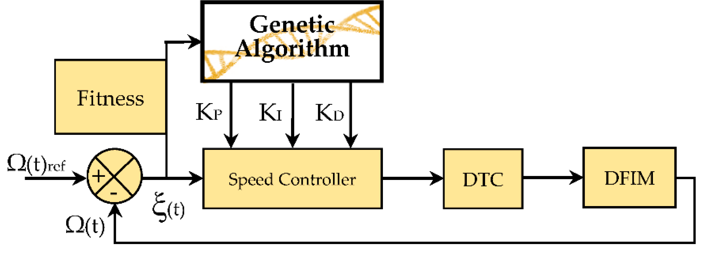
To benefit from the full range of speed variations, minimize the joule losses on the inverters, and overcome the problems listed above, the analysis in this article will concentrate on the study and implementation of the GA-DTC control, which was applied to DFIM connected to two voltage inverters. This architecture has the best advantages mentioned at the beginning of this paragraph. The parameters KP, KI, and KD of the PID speed controller of the DTC are optimized by the GA; Figure 1 shows the proposed structure of the GA-DTC.
GA has been used to solve several types of optimization problems over the last 30 years. They involve many types of problems, such as communication network architecture, database query optimization, and physical device control [22]. As a result, GA has become a robust optimization technique to solve problems related to various fields of technical science [23,24].
The possible improvements in this article are detailed in the following objectives:
  • Minimization of torque and flux ripples influenced by the variation of machine parameters (inverters, hysteresis comparator, flux, and torque estimators).
  • Conservation of DTC control performances.
  • Improvement of speed and electromagnetic torque performances.
  • Reduction of the THD rate of the stator and rotor currents.
This article is organized along the following axes: Section 2 presents the mathematical model of DFIM in the (α, β) plane. Section 3 describes the operation of the DTC control and its internal structure. Section 4 describes the technique for optimizing the parameters of the PID speed controller. Section 5 is focused on the procedure and simulation of the GA-DTC control. Section 6 is devoted to the analysis of the results obtained and the proposal for future research work.

2. Model of the DFIM

The most appropriate model for studying dynamic behavior, and the design and implementation of DTC applied to the DFIM, is the two-phases model, which is expressed by coordinates (α, β). It is represented by the following equations [4,5]:
  • Electrical equations:
{ v s α = R s · i s α + d ψ s α d t v s β = R s · i s β + d ψ s β d t v r α = R r · i r α + d ψ r α d t + ω m · ψ r β v r β = R r · i r β + d ψ r β d t ω m · ψ r α
  • Magnetic equations:
{ ψ s α = L s i s α + L m · i r α ψ s β = L s i s β + L m · i r β ψ r α = L r i r α + L m · i s α ψ r β = L r i r β + L m · i s β
  • Mechanical equations:
T e m = p · ( ψ s α i s β ψ s β i s α )
J · d Ω d t + f · Ω = T e m T r

3. DTC Strategy

The DTC control theory is based on the direct determination of the control pulses applied to the voltage inverter switches. This is achieved to keep the electromagnetic torque, the stator, and rotor fluxes within the predefined hysteresis bands. The application of this technique ensures the decoupling between the torque and the fluxes control. Each voltage inverters enables seven positions in the phase plane, corresponding to eight voltage vector sequences at inverters’ outputs [1].
The purpose of the DTC control is to regulate the electromagnetic torque and fluxes without having measurements of these quantities. However, they are estimated from measurements of the stator and rotor currents of the machine.
In the fixed reference (α, β), the stator and rotor fluxes are estimated from the following equations [4,5]:
{ ψ ¯ s α = ( v ¯ s α R s · i ¯ s α ) d t ψ ¯ s β = ( v ¯ s β R s · i ¯ s β ) d t
{ ψ ¯ r α = ( v ¯ r α R r · i ¯ r α ) d t ψ ¯ r β = ( v ¯ r β R r · i ¯ r β ) d t
The voltages are connected to the commands (Sa, Sb, Sc) of the inverter switches, and the Udcs and Udcr DC voltages that supply these converters and are expressed as follows:
{ v α = 3 2 · U d c ( s , r ) · [ S a ( S b + S c ) ] v β = 1 2 · U d c ( s , r ) · ( S b S c )
Estimated stator and rotor fluxes are calculated in the same way, and they are described by their modules and positions as follows:
{ θ = a r c t g ( ψ ^ β ψ ^ α ) ψ ^ = ψ ^ α 2 + ψ ^ β 2
T ^ e m = p · ( ψ ^ s α · i s β ψ ^ s β · i s α )

3.1. Flux and Torque Correctors

Fluxes are maintained in a circular crown as shown in Figure 2a; this function is performed by two hysteresis comparators with two levels Figure 2c. In addition, a three-level hysteresis comparator controls the electromagnetic torque of the motor in both directions of rotation, producing either positive or negative torque. Figure 2b shows a three-level hysteresis torque comparator.

3.2. Elaboration of the Switching Table

Depending on the sector and the evolution of the fluxes and torque, the Vs and Vr voltage vectors can be used and selected to comply with the fluxes and torque references. The commutation table for selecting the appropriate vectors is shown in Table 1, which is centered on the error of the fluxes ΔΨs, ΔΨr, the error of the torque ΔTem, and the location of the fluxes vectors (i = 1, 2, 3, 4, 5, 6), to control the fluxes and the electromagnetic torque of the DFIM [8].

4. Optimization of the PID Parameters by GA

GAs are a research technique that achieves a compromise balance between the utilization of research space and the exploitation of the best solutions. Theoretical analysis has shown that this compromise is optimally controlled by GAs [22].
In classic DTC control, the speed control is done by a PID controller, which has undesirable overshoots and static errors in nonlinear systems, but this situation cannot be accommodated with the drawbacks of the DTC control and the machine. The optimization of the parameters KP, KI, and KD by the GA enables the generation of optimum values for the PID controller at each sampling time to be adapted to the nonlinearity of the system. Figure 3 demonstrates the reduced structure of the GA optimization method.
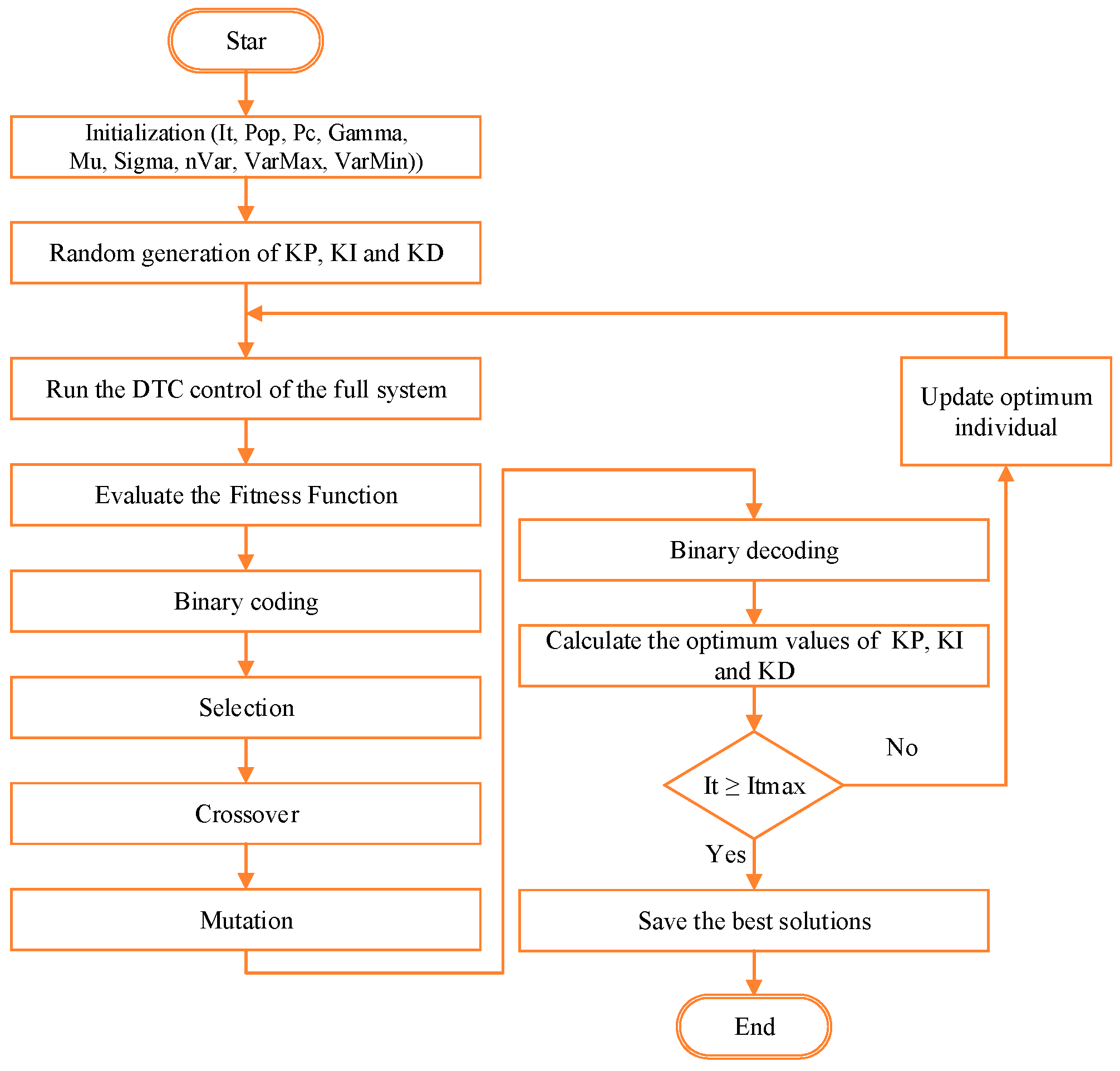
GAs are a special class of evolutionary algorithms that employ techniques inspired by evolutionary biology such as selection, crossover, and mutation [23]. The sequences of operations involved in GA are described in Figure 4, which presents a flowchart, respecting the evolutionary rules of a GA. The proposed new GA-DTC strategy applied on both sides of DFIM is represented by the synoptic structure in Figure 5.
The steps for the execution of the GA are expressed by the Algorithm 1 as follows.
Algorithm 1 Genetic Algorithm
Begin
Step 1. Initialize the algorithm parameters (It, Pop, Pc, Gamma, Mu, Sigma, nVar, VarMax, VarMin).
Step 2. Generate parameters for the PID controller randomly.
Step 3. Execute DTC control of the complete system.
Step 4. Calculate and evaluate the value of the Fitness function.
Step 5. Apply binary coding.
Step 6. Proceed to the selection operation.
Step 7. Proceed to the crossover operation.
Step 8. Proceed to the mutation operation.
Step 9. Proceed to the mutation operation.
Step 10. Apply binary decoding.
Step 11. Update optimum individual and repeat step 3 until the maximum number of iterations has been reached.
Step 12. Save the best solutions.
End

4.1. GA Operators and Parameters

The operation of the GA is based on operators and parameters that ensure its execution and is summarized as follows.

4.1.1. Chromosome Coding

The design of a GA starts with a binary coding of solutions in the form of chromosomes, which are a series of genes or bits, based on the terminology of natural genetics [23]. The primary distinction between the GA and other search optimization algorithms is that GAs use the method of encoding the parameters rather than the parameters themselves. As a result, the critical step in implementing the GA is to choose the most suitable coding form that best represents the problem’s solution space. A GA usually employs the binary coding system. According to the literature, various GA types in the literature use integer, reel numbers, or three schemes, as well as algorithm studies that use different symbolic alphabets [24,25]. The coding method has a significant impact on the efficiency of the GA, but naming the best method is impossible, because the coding method is dependent on the problem itself. Michalewicz demonstrates that using real numbers is easier, but only for a specific problem. Before the coefficient of the PID regulator found by GA in the offline operating mode, the minimum values of the PID regulator’s coefficients and the limits of the PID regulator’s performance must be determined. On the built method, the lower limit value is set to zero coefficients of the PID controller. Not by itself, GA operates on the coded form of the problem. As a result, the encoding format of the problem to be solved has a major impact on GA results. In the literature, two types of encoding are most widely used: weighted binary encoding and actual encoding. The values of the PID coefficients are encoded with a real number as a single chromosome in this study [26].
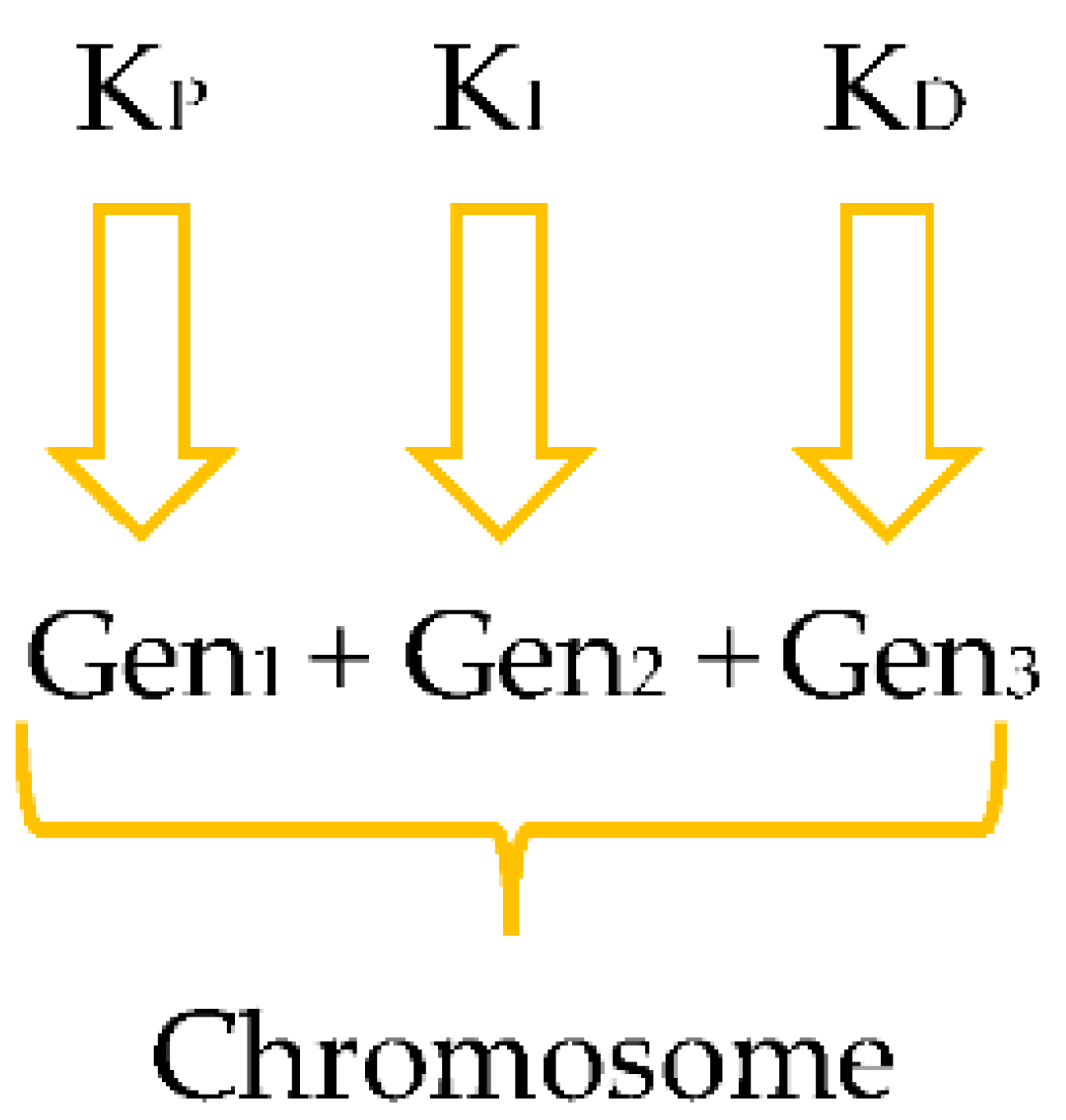
For the PID controller, three parameters are sufficient in this type of coding: KP, KI, and KD. Three genes are needed in this case, if each parameter is viewed as a gene.

4.1.2. Creating First Population

To find the best resolution, the GA searches from multiple points. As a result, it is critical to establish the initial values for these points. Typically, the first population is generated by chance to represent the entire search space. However, some research, particularly in restricted optimization problems, suggests that the first population is generated based on prior information or heuristically [27].

4.1.3. Learning of the PID Gains by GA

The GA parameters have a major impact on the GA’s results. Many studies have been conducted to determine the optimum control parameters [24]. In this work, the Pittsburgh learning approach has been used. This technique is extremely successful in genetic fuzzy systems [25,26]. The PID controller coefficients are encoded in a single chromosome using this method. The resulting chromosomal structure is presented in Figure 6.

4.1.4. Fitness

The critical step in the GA execution is to select the objective functions used to determine the suitability of each chromosome. Some of the works [28,29,30,31] use performance indices as objective functions. In [30], the authors use Mean Squared Error (MSE), Integral Time Absolute Error (ITAE), Integral Absolute Error (IAE), and Integral Square Error (ISE), while in [29,31] the authors use ISE, IAE, and ITAE. In this work, the performance indices used are ISE, ITAE, IAE, and a combination of the three indices, to minimize and compare the error signal e(t) to find the most suitable one. The performance indices shall be described as follows [30]:
I S E = 0 t e ( t ) 2 d t
I A E = 0 t | e ( t ) | d t
I T A E = 0 t t · | e ( t ) | d t
F w = ω 1 I A E + ω 2 I S E + ω 3 I T A E
where
Fw: is the weighted function and e(t) is the error signal.
ω 1 , ω 2 , and ω 3 : are the weights.
The PID controller is used to minimize the error signal e(t), which reduces the value of the specified performance indices, thus minimizing the equivalent value expressed by the chromosomes. With this minimization, the chromosomes will be formed, and the chromosomes’ suitability is determined by:
F i t n e s s _ V a l u e = 1 W e i g h t e d _ F u n c t i o n

4.1.5. Initialization of Populations

A population is a group of individuals who each represent a solution. Some studies have tried to find parameters for population size [24,32,33,34]. There will be sub-optimal solutions if the size is too small because it converges easily, offering minimal solutions. In contrast, it takes too long to have a very large size. Grefenstette confirms that the optimal population size should be between 10 and 160 [25], Odeyato proposed a population size between 100 and 400, and Robertson used a population size of up to 8000 for classification problems [26]. The GA cannot find the desired result for very small values of the population, but in the big population, the computing time will very big. So, different experiment tests were made, and the most appropriate population size is chosen as n = 20.

4.1.6. Selection Operator

Selection is a process in which each person is chosen in proportion to his fitness to create a new population. Individuals are changing across iterations, which are called generations [35]. There are three important methods of selection: The Stochastic Sampling with Replacement Selection Method (SSRS) (or Roulette Wheel), the Universal Stochastic Sampling Method (USS), and the Tournament Selection Method (TS) [33]. The selection operation used in this algorithm is TS because of its best results generated by this technique after the various experimental tests applied to the global system.

4.1.7. Crossover Operator

They consist of exchanging the parent genes to give children who carry combined properties the good genes of one parent, which replace the bad genes of another with different probabilities and create sons who are better adapted than the parents [28]. The probability of crossbreeding must be chosen in the interval [0.6, 0.99] [27,36]. The probability value of crossover operator is selected as 0.8.

4.1.8. Mutation Operator

This operation starts with a random selection of one of the genes on the chromosome, followed by a change in its value with a probability P m , generally speaking, to find an optimal P m value; this value must be in the range [0.001, 0.01] [37]. The probability P m value is chosen as 0.001.

5. Simulation Procedure and Interpretation

The simulation of the GA-DTC control using a PID controller based on the GA of a DFIM, using a weighted combination of the performance indices such as ISE, IAE, and ITAE, is performed on Matlab/Simulink. In order to find the optimal values of the PID controller parameters, the parameters of the GA (VarPmax, VarPmin, VarImax, VarImin, VarDmax, VarDmin, n_iter and Pop) have to be initialized to really big values: (VarPmax = VarImax = VarDmax = 100, VarPmin = VarImin = VarDmin = −100, n_iter = 100, Pop= 100) in order to increase the chance of having the best values for KP, KI, and KD, but in this case, the system only converges after a certain time, which may be days. After this simulation, and starting from the optimal values, the bands of variation of these parameters can be reduced to values close to the optimum, because the system converges toward these highest values. Subsequently, based from these optimal values consequently reducing the number of iterations, as the system converges toward these optimal values, it subsequently reduces the population size. This allows the system to converge rapidly toward the best solution. The values of the PID controller parameters generated by the GA are within the variation bands shown in Table 2; the system is configured with the parameters in Table A1 and Table A2 mentioned in the Appendix A, and the system is subjected to speed and torque references; the Table A3 and Table A4 present the Nomenclature and Abbreviation of the various parameters of the system and the technical terms used in this article.
We have used this algorithm with different DFIMs parameters, and we have noticed that in each case, it generates different values for the PID regulators gains, which correspond to the parameters of the system itself, which will lead to proceed to the above-mentioned steps to have the optimum of each case study. The parameters cited in Table A2 present the optimal parameters of the GA for rotating machines.
The simulation results for the two strategies (conventional DTC and GA-DTC) were tested using a 1.5 kW machine and configured with:
  • The sampling frequency: fs = 10 kHz, this frequency presents the standard frequency used by designers of machine controls, so choosing a frequency lower than 10 kHz results in poor fluxes and torque ripples and undesired THD, and choosing a frequency greater than 10 kHz may not be implemented on programmable boards, especially dSPACE DS 1104 for this type of controls.
  • The widths of the hysteresis bands: ΔTem = ±0.01 Nm, ΔΨs = ±0.001 Wb and ΔΨr = ±0.001 Wb, with the hysteresis comparators, we try to maintain the fluxes and torque variations at bands, which are close to zero, if the bands are greater than to values chosen, it risks having torque and fluxes ripples, and if these bands are lower than the chosen values, it will give the same results, because the comparators will not exceed their capacity limits.
  • Application of a nominal load (TL = 10 Nm and TL = −10 Nm) at t = 1 s and at t = 2.5 s, 10 Nm presents the nominal torque of a 1.5 kW machine, and −10 Nm is the torque in the opposite rotation, because in the instant t = 2.5 s, the rotation direction of the machine is reversed.

5.1. Simulation Results

After several simulation tests, finally, we found the optimal simulation results according to the criteria of choice of the GA parameters, which presents an essential step for all the optimization algorithms to have found the optimal results; the following figures presents the simulation results of the classic DTC and the proposed GA-DTC techniques.

5.2. Interpretation

Speed and torque set points are added to test the tracking capability of the classic DTC, and the proposed GA-DTC is optimized using a weighted combination of the ISE, IAE, and ITAE.
The weights associated with the combined objective functions are ω 1 = 0.4 , ω 2 = 0.2 and ω 3 = 0.4 , because these values are optimal for a weighted combination, as proved by [15].
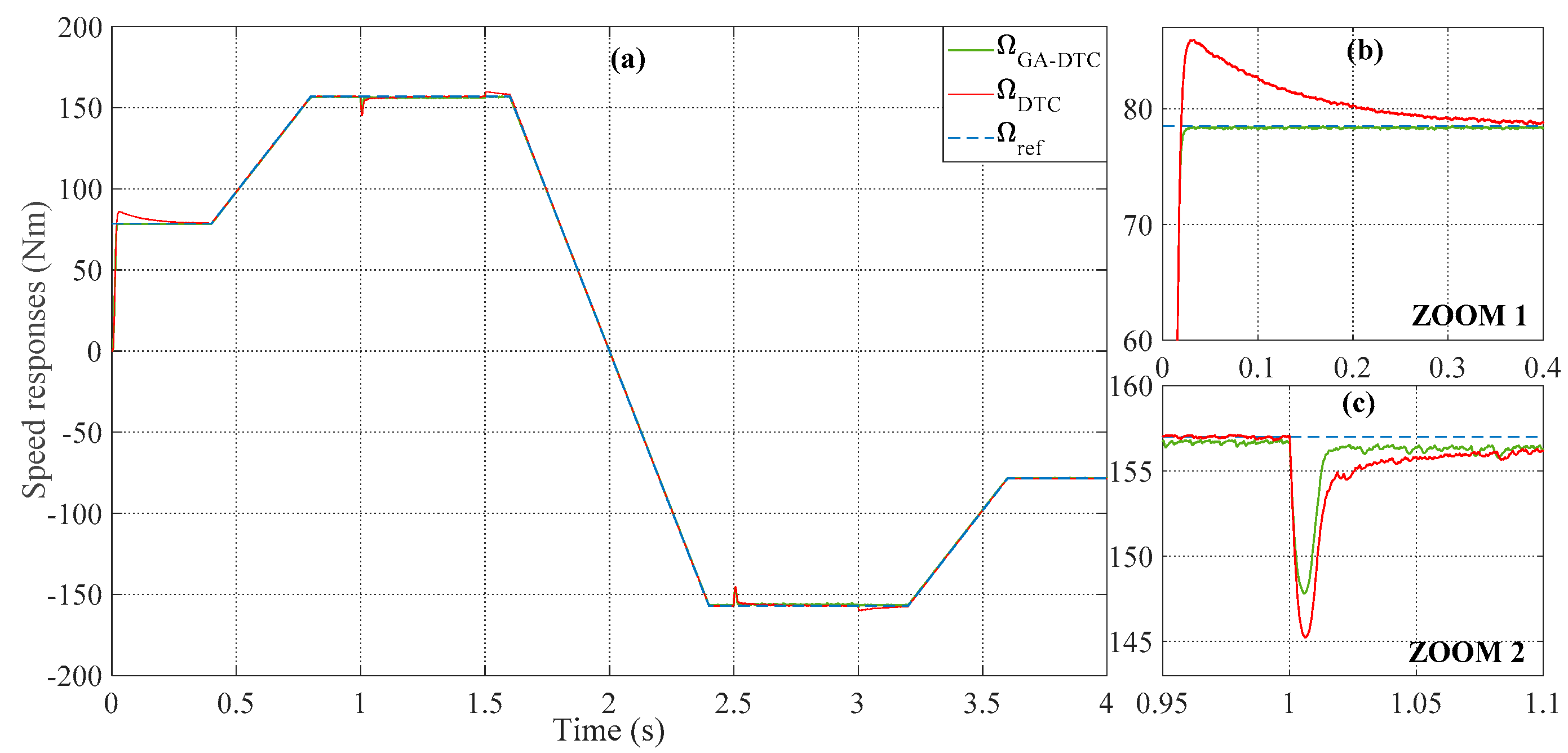
From the responses in Figure 7a–c, the controllers can track the variation of the DFIM speed during no-load and rated load, when the setpoint speed changes from 78.5 to 157 rad/s, and from −157 to −78.5 rad/s. The PID controller in both conventional DTC and weighted GA-DTC controls installs faster in all setpoint transitions. The speed performance measures, such as overshoot, response time, and rejection time, are as shown in Table 3.
From the responses in Figure 7a,b, the overshoot is negligible for the weighted combination GA-DTC compared to the classical DTC by an improvement of 100%. The proposed GA-DTC control using a weighted combination shows a considerable improvement in response time of 82.67% (105 ms for classic DTC control, and 18.2 ms for weighted GA-DTC control), such that the undershoot is reduced by 21.94% in the loaded condition (9.18 rad/s for conventional DTC control, and 11.76 rad/s for weighted GA-DTC control).
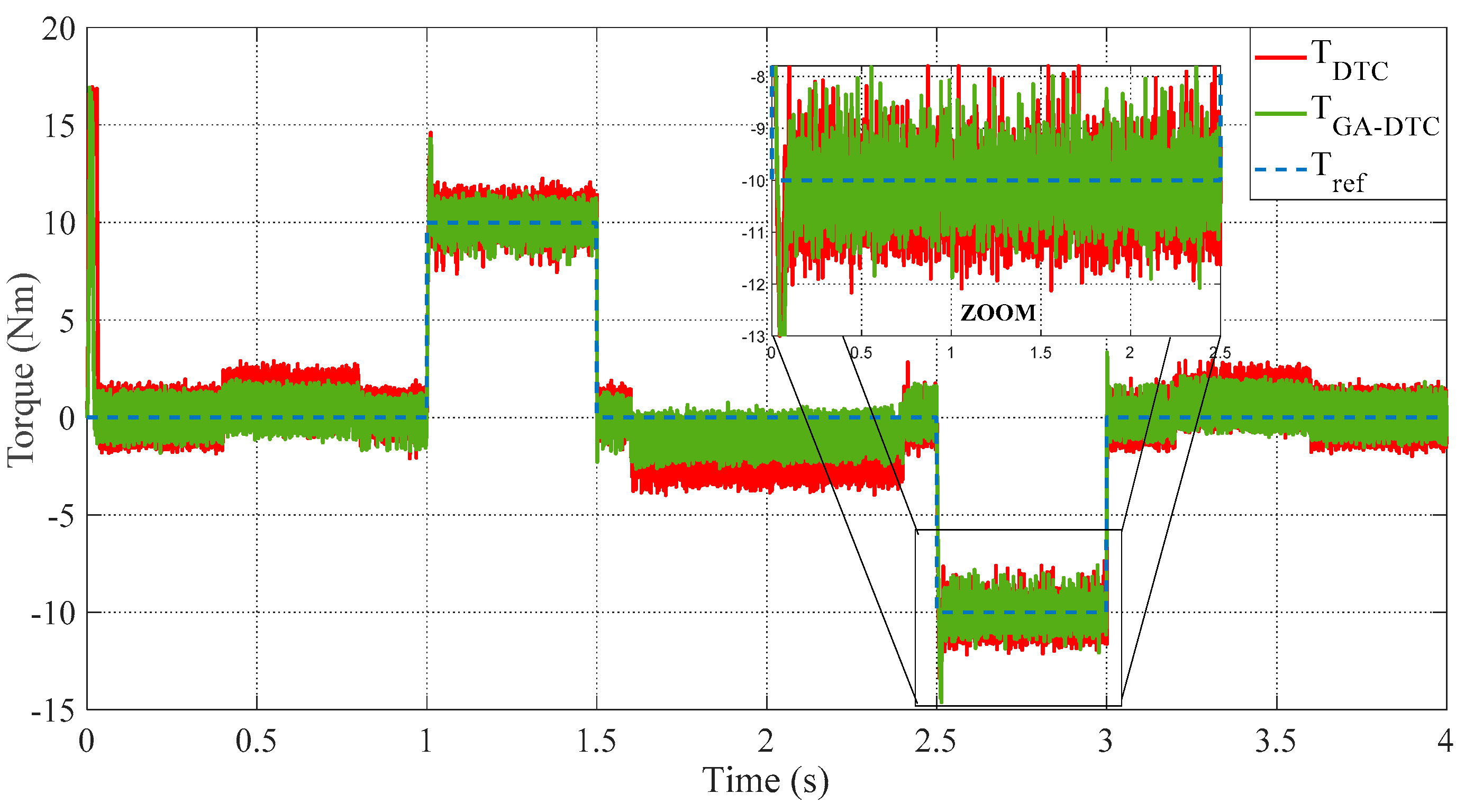
The electromagnetic torque responses tracking curves are shown in Figure 8. The proposed GA-DTC control using a weighted combination shows an important improvement in terms of electromagnetic torque ripples, which are minimized in the maximum possible of 16.16% (2.445 Nm for conventional DTC control, and 2.05 Nm for weighted GA-DTC control), which shows the robustness of GA-DTC control for optimum PID controller gain choices.
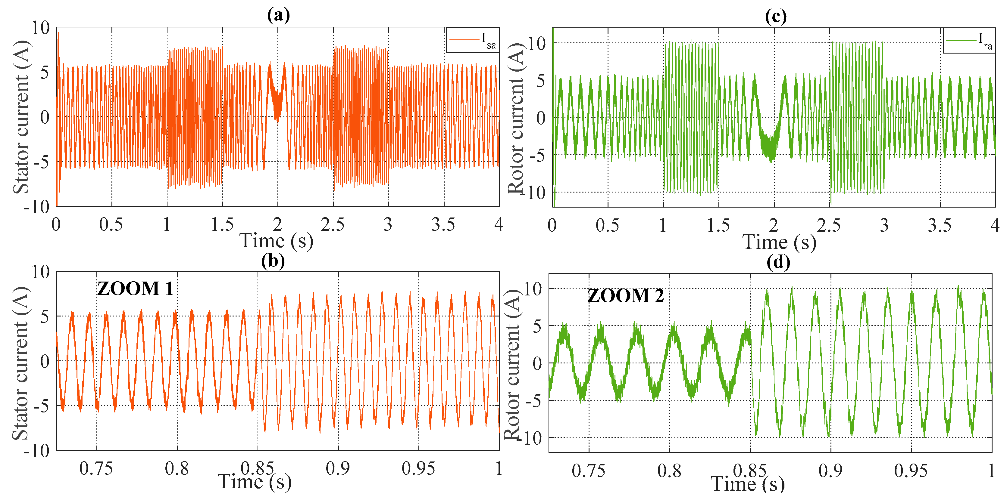
Figure 9a,b and Figure 11a,b demonstrates, respectively, the stator and rotor currents. and its harmonic spectral analysis of classic DTC and optimized DTC using weighted objective functions, presented in the Figure 10a,b and Figure 12a,b that show a THD reduction by 53.76% of the stator currents, and a reduction by 34.55% of the rotor currents (10.38% and 11.52% for conventional DTC control of the stator and rotor currents respectively, 4.8% and 7.54% for weighted GA-DTC control of the stator and rotor currents respectively).
Figure 13a,b illustrates the waveform of the stator and rotor fluxes for conventional DTC and the proposed GA-DTC controls. The latter has good dynamics, which significantly reduces the stator and rotor ripples, respectively by 29.71%, and 24.32% (0.06123 Wb and 0.0118 Wb for the conventional DTC control, and 0.04304 Wb and 0.00893 Wb for the weighted GA-DTC control). Therefore, these properties make the GA suitable for applications having special performance.
Table 3 shows that a weighted combination of objective functions such as ISE, IAE, and ITAE results in a greater reduction in the percentage of peak overshoot and response time, and thus in the rejection time compared to the classical DTC, these results are obtained with the parameters of the PID regulators expressed in Table 4 for both controls.
From the previous interpretations and reduced Table 3 presented by the different performances, our proposal GA-DTC has confirmed the objectives proposed in the Introduction, which shows the robustness of this technique in terms of speed, ripples fluxes, torque, and the THD of currents.
The improvements attributed by GA to the classic DTC control allow control of the DFIM with better reliability in the different conditions of use and installation environment, because the GA-DTC strategy adapts with the parametric variations of the machine, thanks to the variation of the PID speed controller gains according to the physical situation, which allows it to be the right choice for the variable speed drives.

6. Conclusions

The optimal behaviors of the DFIM are founded by using a new approach based on the GA technique applied to DTC, to generate optimums values of the PID parameters controller, to increase the performances of the DFIM in terms of speed, torque, and fluxes ripples, and THD of the stator and rotor currents.
The optimization of the KP, KI, and KD parameters of the PID controller in the GA-DTC strategy, was designed and applied to a DFIM powered by two voltage inverters. DFIM modeling and descriptions of the GA-DTC control have been presented, and the simulation studies have shown that the optimized controller parameters obtained by implementing this algorithm with a weighted combination of ISE, IAE, and ITAE as performance indices.
The new strategy proposed in this work has been giving several improvements which are summarized by the following points:
  • The response time, rejection time, and overshoot are improved by 82.67%, 72.21%, and 100%, respectively.
  • The electromagnetic torque ripples are reduced by 16.16%.
  • Minimization of THD in stator and rotor currents by 53.76% and 34.55%, respectively.
The GA-DTC control has improved the robustness of the conventional DTC control, increasing its performances in transient and dynamic conditions in terms of efficiency, rapidity, precision, and stability.
To promote technological and scientific research, future study will be dedicated to the following areas:
  • The implementation of this control on an experimental prototype, to test the GA-DTC control.
  • Reduction of the effect of the hysteresis comparators by using the ANN controller.

Author Contributions

Conceptualization, S.M. and N.E.O.; methodology, A.D.; software, S.M.; validation, S.M., A.D. and N.E.O.; formal analysis, S.M. investigation, A.D.; resources, A.D.; data curation, A.D.; writing—original draft preparation, S.M.; writing—review and editing, S.M., A.D., N.E.O., M.E.M. and M.T.; visualization, S.M.; supervision, A.D.; project administration, A.D.; funding acquisition, S.M. and N.E.O. All authors have read and agreed to the published version of the manuscript.

Funding

This research received no external funding.

Institutional Review Board Statement

Not applicable.

Informed Consent Statement

Not applicable.

Data Availability Statement

Not applicable.

Conflicts of Interest

The authors declare no conflict of interest.

Appendix A

Table A1. DFIM parameters.
SymbolsValues (Unit)
P n 1.5 Kw
V s 400 v
V r 130 v
P 2
f 50 Hz
R s 1.75 Ω
R r 1.68 Ω
L s 0.295 H
L r 0.104 H
M 0.165 H
f 0.0027 kg.m2/s
J 0.01 kg.m2
Table A2. Parameters of the GA.
DescriptionType/Value
Population size20
Maximum iteration50
Crossover Probability0.9
Mutation Probability0.001
Beta1
Sigma0.1
Gamma0.1
CodingBinary
SelectionUniform
CrossoverRoulette Wheel Selection
MutationUniform
Table A3. Nomenclature.
ParametersDescription
V, V,V and VStator and rotor voltages in (α, β) plan
Udcs and UdcrStator and rotor directs voltages
I, I, I, and IStator and rotor currents in (α, β) plan
Ψ, Ψ, Ψ, and ΨStator and rotor fluxes in (α, β) plan
Rs, RrStator and rotor resistors
Ls, LrStator and rotor inductors
LmMutual Inductance
PNumber of pairs of poles
ωrRotor angular speed
ωsStator angular speed
Rotation speed
TemElectromagnetic torque
TrResistant torque
fViscous friction coefficient
JMoment of inertia
Table A4. Abbreviation table.
AbbreviationWording
DFIMDoubly Fed Induction Motor
DTCDirect Torque Control
GAGenetic Algorithm
GA-DTCGenetic Algorithm-Direct Torque Control
PIDProportional Integrator Derivator
DTFCDirect Torque Fuzzy Control
DTNCDirect Torque Neural Control
DTNFCDirect Neural Fuzzy Torque Control
ANFISAdaptive Neuro-Fuzzy Inference System

References

  1. Takahashi, I.; Ohmori, Y. High-performance direct torque control of an induction motor. IEEE Trans. Ind. Appl. 1989, 25, 257–264. [Google Scholar] [CrossRef]
  2. Takahashi, I.; Noguchi, T. Take a look back upon the past decade of direct torque control [of induction motors]. In Proceedings of the IECON’97 23rd International Conference on Industrial Electronics, Control, and Instrumentation (Cat. No. 97CH36066), New Orleans, LA, USA, 14 November 1997; Volume 2, pp. 546–551. [Google Scholar]
  3. Baader, U.; Depenbrock, M.; Gierse, G. Direct self control (DSC) of inverter-fed induction machine: A basis for speed control without speed measurement. IEEE Trans. On Ind. Appl. 1992, 28, 581–588. [Google Scholar] [CrossRef]
  4. Khadar, S.; Kouzou, A. Dual Direct Torque Control of Doubly Fed Induction Machine using Artificial Neural Network. In Proceedings of the 2018 3rd International Conference on Pattern Analysis and Intelligent Systems (PAIS), Tebessa, Algeria, 24–25 October 2018; pp. 1–7. [Google Scholar] [CrossRef]
  5. El Ouanjli, N.; Derouich, A.; Ghzizal, A.E.L.; Motahhir, S.; El Mourabit, Y.; Taoussi, M. Modern improvement techniques of direct torque control for induction motor drives—A review. Prot. Control Mod. Power Syst. 2019, 7, 11. [Google Scholar] [CrossRef] [Green Version]
  6. Abbas, A.S.; El-Sehiemy, R.A.; El-Ela, A.; Ali, E.S.; Mahmoud, K.; Lehtonen, M.; Darwish, M.M. Optimal Harmonic Mitigation in Distribution Systems with Inverter Based Distributed Generation. Appl. Sci. 2021, 11, 774. [Google Scholar] [CrossRef]
  7. Mahfoud, S.; Derouich, A.; El Ouanjli, N.; Mohammed, T.; Hanafi, A. Field Oriented Control of Doubly Fed Induction Motor using Speed Sliding Mode Controller. E3s Web Conf. Edp Sci. 2021, 229, 01061. [Google Scholar] [CrossRef]
  8. El Ouanjli, N.; Derouich, A.; El Ghzizal, A.; Chebabhi, A.; Taoussi, M.; Bossoufi, B. Direct torque control strategy based on fuzzy logic controller for a doubly fed induction motor. Iop Conf. Ser. Earth Environ. Sci. 2018, 161, 012004. [Google Scholar] [CrossRef]
  9. Menghal, P.M.; Laxmi, A.J. Real time control of induction motor using neural network. In Proceedings of the 2018 International Conference on Communication information and Computing Technology (ICCICT), Mumbai, India, 2–3 February 2018; pp. 1–6. [Google Scholar] [CrossRef]
  10. Grabowski, P.Z.; Kazmierkowski, M.P.; Bose, B.K.; Blaabjerg, F. A simple direct-torque neuro-fuzzy control of PWM-inverter-fed induction motor drive. IEEE Trans. Ind. Electron. 2000, 47, 863–870. [Google Scholar] [CrossRef]
  11. Banda, G.; Kolli, S.G. An Intelligent Adaptive Neural Network Controller for a Direct Torque Controlled eCAR Propulsion System. World Electr. Veh. J. 2021, 12, 44. [Google Scholar] [CrossRef]
  12. Taoussi, M.; Karim, M.; Bossoufi, B.; Hammoumi, D.; Lagrioui, A.; Derouich, A. Speed variable adaptive backstepping control of the doubly-fed induction machine drive. Int. J. Of Autom. Control 2016, 10, 12–33. [Google Scholar] [CrossRef]
  13. Pujar, J.; Kodad, S. Robust Sensorless Speed Control of Induction Motor with DTFC and Fuzzy Speed Regulator. Int. J. Electr. Comput. Eng. 2011, 5, 1041–1050. [Google Scholar] [CrossRef]
  14. Zemmit, A.; Messalti, S.; Harrag, A. A new improved DTC of doubly fed induction machine using GA-based PI controller. Ain Shams Eng. J. 2018, 9, 1877–1885. [Google Scholar] [CrossRef]
  15. Das, K.R.; Das, D.; Das, J. Optimal tuning of PID controller using GWO algorithm for speed control in DC motor. In Proceedings of the 2015 International Conference on Soft Computing Techniques and Implementations (ICSCTI), Faridabad, India, 8–10 October 2015; pp. 108–112. [Google Scholar] [CrossRef]
  16. Madadi, A.; Motlagh, M.M. Optimal control of DC motor using grey wolf optimizer algorithm. Tech. J. Eng. Appl. Sci. 2014, 4, 373–379. [Google Scholar]
  17. Kanojiya, R.G.; Meshram, P.M. Optimal tuning of PI controller for speed control of DC motor drive using particle swarm optimization. In Proceedings of the 2012 International Conference on Advances in Power Conversion and Energy Technologies (APCET), Mylavaram, India, 2–4 August 2012; pp. 1–6. [Google Scholar]
  18. Ayala HV, H.; dos Santos Coelho, L. Tuning of PID controller based on a multiobjective genetic algorithm applied to a robotic manipulator. Expert Syst. Appl. 2012, 39, 8968–8974. [Google Scholar] [CrossRef]
  19. Krohling, R.A.; Rey, J.P. Design of optimal disturbance rejection PID controllers using genetic algorithms. IEEE Trans. On Evol. Comput. 2001, 5, 78–82. [Google Scholar] [CrossRef]
  20. Nagaraj, B.; Murugananth, N. A comparative study of PID controller tuning using GA, EP, PSO and ACO. In Proceedings of the 2010 International Conference on Communication Control and Computing Technologies, Nagercoil, India, 7–9 October 2010; pp. 305–313. [Google Scholar]
  21. Elsisi, M.; Tran, M.Q.; Mahmoud, K.; Lehtonen, M.; Darwish, M.M. Robust Design of ANFIS-Based Blade Pitch Controller for Wind Energy Conversion Systems Against Wind Speed Fluctuations. IEEE Access 2021, 9, 37894–37904. [Google Scholar] [CrossRef]
  22. El Ouanjli, N.; Derouich, A.; El Ghzizal, A.; Bouchnaif, J.; El Mourabit, Y.; Taoussi, M.; Bossoufi, B. Real-time implementation in dSPACE of DTC-backstepping for a doubly fed induction motor. Eur. Phys. J. Plus 2019, 134, 566. [Google Scholar] [CrossRef]
  23. Jayachitra, A.; Vinodha, R. Genetic Algorithm Based PID Controller Tuning Approach for Continuous Stirred Tank Reactor. Adv. In Artif. Intell. 2014, 2014, 791230. [Google Scholar] [CrossRef]
  24. Yusoff, T.A.F.K.; Atan, M.F.; Rahman, N.A.; Salleh, S.F.; Wahab, N.A. Optimization of pid tuning using genetic algorithm. J. Of Appl. Sci. Process Eng. 2015, 2. [Google Scholar] [CrossRef] [Green Version]
  25. Meena, D.C.; Devanshu, A. Genetic algorithm tuned PID controller for process control. In Proceedings of the 2017 International Conference on Inventive Systems and Control (ICISC), Coimbatore, India, 19–20 January 2017; pp. 1–6. [Google Scholar]
  26. Schockenhoff, F.; Zähringer, M.; Brönner, M.; Lienkamp, M. Combining a Genetic Algorithm and a Fuzzy System to Optimize User Centricity in Autonomous Vehicle Concept Development. Systems 2021, 9, 25. [Google Scholar] [CrossRef]
  27. Krajčovič, M.; Hančinský, V.; Dulina, Ľ.; Grznár, P.; Gašo, M.; Vaculík, J. Parameter setting for a genetic algorithm layout planner as a toll of sustainable manufacturing. Sustainability 2019, 11, 2083. [Google Scholar] [CrossRef] [Green Version]
  28. Amirjanov, A. The parameters setting of a changing range genetic algorithm. Nat. Comput. 2015, 14, 331–338. [Google Scholar] [CrossRef]
  29. Angelova, M.; Pencheva, T. Tuning genetic algorithm parameters to improve convergence time. Int. J. Of Chem. Eng. 2011. [Google Scholar] [CrossRef] [Green Version]
  30. Zhao, J.; Xi, M. Self-Tuning of PID Parameters Based on Adaptive Genetic Algorithm. In IOP Conference Series: Materials Science and Engineering; Modern Control Systems; Dorf, R.C., Bishop, R.H., Eds.; IOP Publishing: London, UK; Pearson: London, UK, 2020; Volume 782, p. 042028. [Google Scholar]
  31. Chlaihawi, A.A. Genetic algorithm error criteria as applied to PID controller DC-DC buck converter parameters: An investigation. In IOP Conference Series: Materials Science and Engineering; IOP Publishing: Bristol, UK, 2020; Volume 671, p. 012032. [Google Scholar] [CrossRef]
  32. Qin, Y.; Zhao, G.; Hua, Q.; Sun, L.; Nag, S. Multiobjective genetic algorithm-based optimization of PID controller parameters for fuel cell voltage and fuel utilization. Sustainability 2019, 11, 3290. [Google Scholar] [CrossRef] [Green Version]
  33. Happyanto, D.C.; Wijayanto, A. Implementation of Genetic Algorithm for Parameter Tuning of PID Controller in Three Phase Induction Motor Speed Control. IPTEK J. Eng. 2014, 1. [Google Scholar] [CrossRef]
  34. Zahir, A.A.M.; Alhady, S.S.N.; Othman, W.A.F.W.; Ahmad, M.F. Genetic algorithm optimization of PID controller for brushed DC motor. In Intelligent Manufacturing Mechatronics; Springer: Singapore, 2018; pp. 427–437. [Google Scholar]
  35. Bharadwaj, C.S.; Babu, T.S.; Rajasekar, N. Tuning PID Controller for Inverted Pendulum Using Genetic Algorithm. In Advances in Systems, Control and Automation; Springer: Singapore, 2018; pp. 395–404. [Google Scholar]
  36. Tran, T.C.; Brandstetter, P.; Duy, V.H.; Vo, H.H.; Dong, C. PID speed controller optimization using online genetic algorithm for induction motor drive. In International Conference on Advanced Engineering Theory and Applications; Springer: Cham, Switzerland, 2016; pp. 564–576. [Google Scholar]
  37. Harrag, A.; Messalti, S. Variable step size modified P&O MPPT algorithm using GA-based hybrid offline/online PID controller. Renew. Sustain. Energy Rev. 2015, 49, 1247–1260. [Google Scholar] [CrossRef]
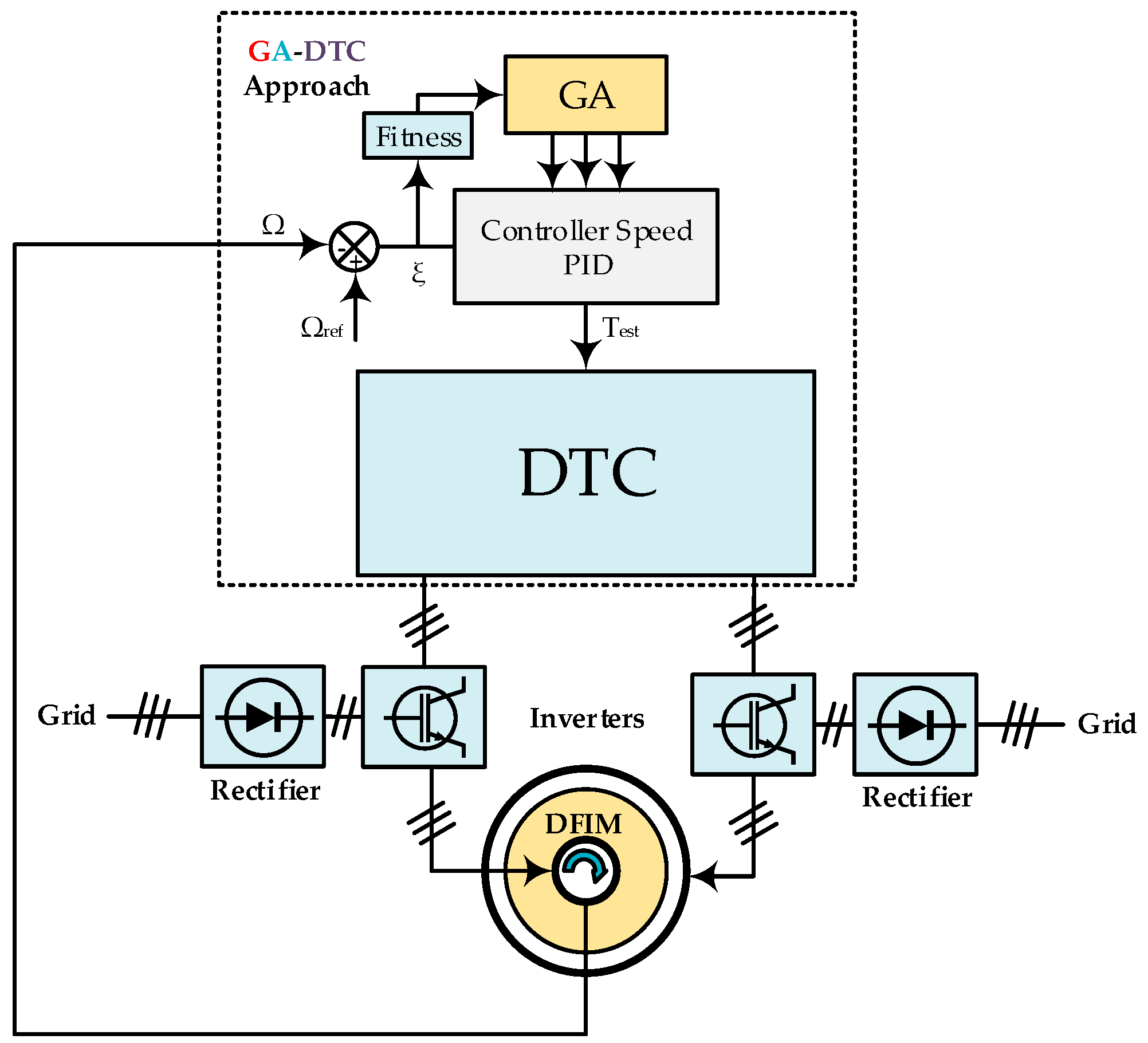
Figure 1. Global structure of proposal GA-DTC technique.
Systems 09 00037 g001
Figure 2. (a) Fluxes trajectory, (b) three-level torque hysteresis comparator; and (c) two-level flux comparators.
Systems 09 00037 g002
Figure 3. Optimization of the PID controller parameters by the GA.
Systems 09 00037 g003
Figure 4. Flowchart of the GA.
Systems 09 00037 g004
Figure 5. GA-DTC control schematic applied to DFIM.
Systems 09 00037 g005
Figure 6. Chromosome structure created for PID controller.
Systems 09 00037 g006
Figure 7. Speed responses (ac) of the DTC control and GA-DTC.
Systems 09 00037 g007
Figure 8. Torque responses of the DTC control and GA-DTC.
Systems 09 00037 g008
Figure 9. Stator (a,b) and rotor (c,d) currents of the DTC.
Systems 09 00037 g009
Figure 10. THD of the stator (a) and rotor (b) currents of the DTC.
Systems 09 00037 g010
Figure 11. Stator (a,b) and rotor (c,d) currents of the GA-DTC.
Systems 09 00037 g011
Figure 12. THD of the stator (a) and rotor (b) currents of the GA-DTC.
Systems 09 00037 g012
Figure 13. Stator (a,c) and rotor (b,d) fluxes of the GA-DTC.
Systems 09 00037 g013
Table 1. The inverter sequences.
Sector Si
HΨs or HΨrHTemS1S2S3S4S5S6
11v2v3v4v5v6v1
0v7v0v7v0v7v0
−1v6v1v2v3v4v5
01v3v4v5v6v1v2
0v0v7v0v7v0v7
−1v5v6v1v2v3v4
Table 2. The PID parameters band.
PID ParametersKPKIKD
Maximum Value100101
Minimum Value000
Table 3. Performance measures of classic DTC and GA-DTC.
CharacteristicsWeighted GA-DTCDTCImprovement (%)
ωResponse Time (ms)18.210582.67
Overshoot (rad/s)07.43100
Rejection Time (ms)0.1750.80372.21
Undershoot (rad/s)9.1811.7621.94
TemRipples (Nm)2.052.44516.16
ΨsRipples (wb)0.043040.0612329.71
ΨrRipples (wb)0.008930.011824.32
isaTHD (%)4.810.3853.76
IraTHD (%)7.5411.5234.55
Table 4. Parameters of PID controller under DTC and GA-DTC.
Controller ParametersClassic DTCWeighted GA-DTC
KP1872.8895
KI0.80.0729
KD00.5262
Publisher’s Note: MDPI stays neutral with regard to jurisdictional claims in published maps and institutional affiliations.