Abstract
In product development, costs play a major role in making design decisions. As such, it is desirable to have this information as early as possible in the product development process (PDP). The development of systems changes in the direction of Model-Based Systems Engineering (MBSE) with a system model containing all information. The product costs thus need to be considered in MBSE approaches and system models. In the early stages, cost calculation models are rough estimates and will become more refined over the course of the PDP. The flow of information between the product information and cost calculation models takes a long time, and multiple calculations need to be updated before the product cost can be calculated. In this contribution, we show how cost types like the manufacturing cost or purchase cost can be seamlessly integrated into a hierarchical product structure, and cost calculation models can be linked. We present how cost calculation models with different granularity can be changed over the course of the PDP and how the product cost calculation is affected when a specific factor of the product changes. In this contribution, the case of the electrohydraulic actuator (EHA) developed in the project “Dezentrale Hydraulik II” is used.
1. Introduction
Product design has a significant influence on cost definition and cost generation. As 70% of the product cost is determined by development and design, they are the dominant contributors [1,2]. Products are influenced by external factors like the pressure of competition, demanding customer requirements, expectations of stakeholders, and regulations [3]. This leads to high pressure in the development of products, with a significant influence on the product costs, to reduce the product cost as far as possible, while still satisfying the given external factors. As such, it is advantageous to have cost calculations as early as possible and continuously in the product development process, to base design decisions on these cost calculations. Traditional cost estimations are performed with a given geometry at the end of any step in the design process [4] and are based on information given from the development department to the controlling department, which then, in turn, needs to obtain information from the manufacturing, logistics, and purchasing departments, as well as potential external departments and sources. This leads to a sequential cost calculation in multiple documents, with a process prone to errors due to the manual transfer of data in calculation tables [5,6,7,8,9,10,11,12].
Model-based systems engineering is an approach that utilizes models and modeling tools to enhance the development process. In a function-oriented approach of MBSE, a function model and a logical model are derived from the requirements, which are in turn derived from stakeholder expectations and use cases. From the functional and logical descriptions of the product, the physical part is developed. The modeling of requirements, the functional and logical architecture, as well as the product architecture, is integrated into a so-called system model. It consists of system elements, such as functions or assemblies [13]. The system model acts as a single point of truth (SPOT) that provides all relevant data to the models, e.g., cost calculation models [13]. For every single change to the product, it is not necessary to implement this change manually in different documents [14] but the change made by, for example, the design department is made in the SPOT, and the cost department can use the same SPOT to calculate the product cost. This prevents transfer errors and the resulting discrepancies [14]. With the usage of MBSE and the associated SPOT, efficiency and productivity can thus be increased [13]. In addition, calculation models can be implemented in libraries; as such, the reusability of models becomes more practical and efficient, which in turn saves time and costs when used several times [15]. Therefore, the model reusability is very advantageous for cost calculations as the same cost calculations are used for different parts of the product repeatedly [16]. During the PDP cost calculation, models with different accuracy need to be used. For example, an estimation model early on and a very detailed model late in the PDP. As such, an interchangeability of the cost calculation models is needed.
The problem that still exists is the complete integration of existing cost models into MBSE modeling methods, so that the benefits of MBSE can amplify the cost calculation with an early cost calculation, reduced data handling errors, as well as reduced manual effort. The goal of this contribution is to show a method to calculate product costs in the context of function-oriented MBSE.
The requirements for the presented approach are as follows: firstly, the seamless use of early cost calculations during the PDP; secondly, the ability to change the calculation models over the course of the PDP; thirdly, cost calculation based on the technical parameters from the SPOT; and fourthly, the ability to calculate the product cost at multiple different time steps in the PDP.
2. State of the Art (Materials and Methods)
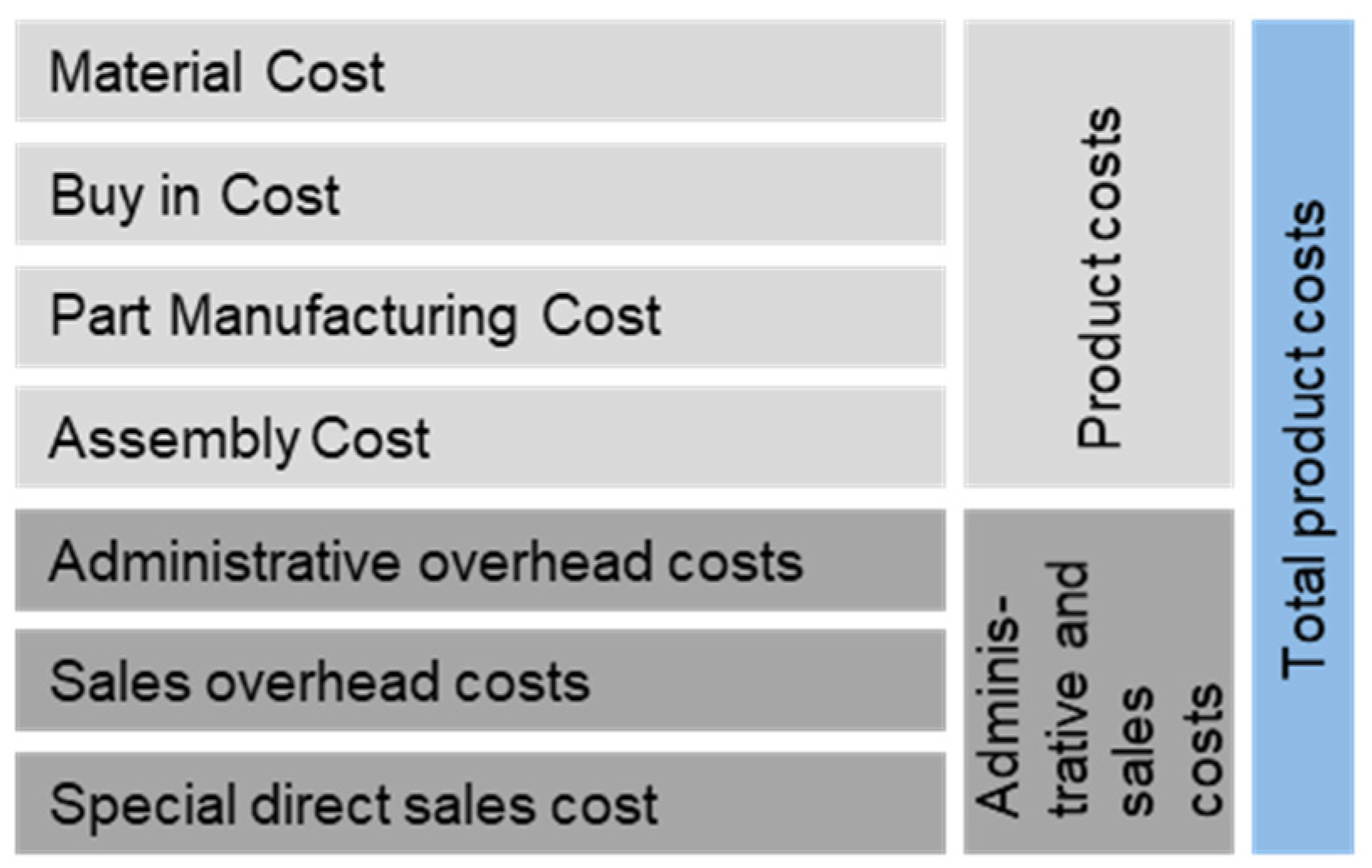
Normally, the total product costs are an aggregation of the product cost, as well as the administrative and sales costs. For this contribution, the focus is on the product cost, which in turn is an aggregation of material cost, buy-in cost, part manufacturing cost, and assembly cost. These costs are influenced by the development of the product. The total product cost, as well as margins for the sale of the product, are out of scope for this contribution, as they are not directly influenced by the product development [17]. This aggregation is shown in Figure 1.

Figure 1.
Product cost aggregation, adapted from [17].
As such, two steps are necessary to obtain the product cost. Firstly, the cost calculation for the material cost, part manufacturing cost, assembly cost, and buy-in cost for every part and assembly of the respective product. Secondly, the aggregation of these singular calculated costs to the product cost.
2.1. Product Cost Calculation
For the calculation of the material cost, part manufacturing cost, assembly cost, and buy-in cost, multiple models exist in the literature. In this contribution, no new model is developed; the models shown during this contribution are only used for the example later in the contribution. For this contribution, the cost calculation in the early and late steps of the PDP is considered. The main difference between these two steps is the information present at that moment.
Early in the PDP, only estimated values can be given for the product, e.g., estimated part weight, material use, or production time. The geometry is only in rough sketches or CAD models. Other information is not yet considered, e.g., the assembly line is not detailed early on. As such, the calculation models focus on estimating the costs by using historical data from similar parts, e.g., the machining time is estimated and multiplied by the operator rate and the machine cost. The models vary in the amount of information that is used to calculate the costs and, as such, vary in fidelity. For example, the machining cost can use a general set for the machine rate that includes machine, operator, and tool changing time, or these three are considered separately [18]. For the assembly cost calculation, Hartmann [19] is an example of an estimation model for bolt connections.
In the state of the art, the known models have generally no connection to an MBSE system model. As such, no new formula for cost calculation is needed, yet an integration into an MBSE system model is. For this Spütz et al. [20] elaborated a method for the integration of production costs models into the MBSE methodology, motego (abbreviation for Model-Test-Go, former MSE Architecture [21]). It is also extendable to other SysML-based methodologies. The integration is conducted by using so-called “Domain Models”, which are directly integrated into the respective elements of the system model [20]. This integration was further extended for various purposes [16]. The presented approach from a combination of [16,20] gives only the manufacturing cost calculation for a singular element of the product, not the product cost. Missing from the product cost are the integration of non-manufactured, e.g., bought-in parts, as well as the calculation of assembly costs. Also not presented is a way to aggregate the singular cost of the element to the product cost. As such, the approach is not yet usable for the calculation of the product cost, but can be expanded.
2.2. Product Cost Aggregation
For the aggregation of the material cost, part manufacturing cost, assembly cost, and buy-in cost, some approaches are shown in the literature. A selection is shown here.
Firstly, Weustink et al. [4] present a method for manufacturing cost estimation. The product is hierarchically divided into elements. These elements are primarily parts and assemblies, but also singular faces or features of a part. For each element, four main cost-driving characteristics are listed. These are geometry, material, production process, and production planning. All of them are interrelated underneath. For example, the geometry costs can be influenced by the choice of shape or surface roughness. The specification of these two parameters is essential for the choice of material and the production process. The four main cost-driving characteristics can be separated into different levels of aggregation. The method to calculate costs is to calculate values for the four characteristics, starting on the lowest level, here a feature or face of a part, and doing this to the topmost level. The resulting product costs are derived by adding up all specific costs related to geometry, material, process, and production plan at each system level. This way of distributing the costs over the elements of the product and aggregating these costs to product costs is very usable, yet the usability in early stages of the PDP is limited, as the four characteristics of the faces, parts, and assemblies need to be known. The models for calculating the cost values for the four characteristics, how these models are connected to the hierarchy, and the storage of the underlying data are not described. This method is not yet connected to MBSE.
Secondly, Van der Laan et al. [22] represent in their paper an open-source estimation tool for part manufacturing costs. The tool is based on the calculation of costs for each manufacturing step, which is divided into material costs and used material, per step of the manufacturing time slot. The time slot depends on the manufacturing type of the geometry of the product. The material cost is the multiplication of the material quantity and the material unit cost. The assembly costs are only described by the so-called connection material data. This connection material data specifies the assembly method, e.g., gluing or bolting, and gives this assembly method a monetary value per unit, e.g., bolting a hex bolt costs 31 cents per unit. The information necessary for the calculation includes manufacturing processes, manufacturing method data, manufacturing environmental data, material data, and connection material data. The tool with these data is provided in Python 3. However, it must be critically considered that this method, and as such, the tool, has cost deviations of up to 50% compared to other cost calculation programs. Due to this deviation, the method can only give tendencies, not absolute values. This method uses very specific and changeable models for the calculation of manufacturing costs of parts, yet the assembly costs are not calculated by a specific model. Though the method uses a good hierarchical data structure with parts and assemblies with underlying data, the method and the models are not obviously connected to MBSE and are standalone from the information of the product, thus not using a SPOT. As the models need detailed manufacturing data, such as specified geometric data, to calculate the costs, the use early in the PDP is limited [22].
Thirdly, Batarseh et al. [23] represent a detailed SysML model for production cost estimation. They differentiate between resources, products, and processes. The resources are classified as human or machine, the products in final product and part, and the processes in offline, assembly, troubleshooting, rework, inspection, test, and environmental stress test processes. Each element of the production line, from a “ScanTester” to the staff shifts, is modeled. With activity diagrams, all these processes, used resources, and the time of processes are put in order for each part of the product. This diagram calculates the costs for each module. This method is very good for the cost calculation for almost finished products, as it needs the complete manufacturing process in detail, yet the information for the complete manufacturing process is not available in the early stages, and as such, the method is not usable early in the PDP. It is not displayed whether another model is usable for the calculation of a part cost. The origin of the information for the calculation is not described [23].
The presented aggregation approaches intertwine the calculation of the cost with the aggregation of the cost. They are, to an extent, based on SysML and as such also usable in an MBSE context, even if it is not explicitly shown. As such, they could use the data from a system model (SPOT) to calculate the product cost. The overhanging disadvantage is the information needed. All presented methods need more information than is available in the early stages of the PDP.
While the amount of information about the product and thus the aforementioned calculation models change during the PDP, the aggregation structure, however, stays the same and needs to cope with changing models. As such, an interchangeability of models for the cost calculation with a “modular” aggregation to the product cost is needed, but has not yet been shown in the literature. So, there is a need to develop a cost aggregation method for the entire product in an MBSE system model, which is not restricted to a specific use case and can be extended with different calculation models. From this, the research questions for this contribution can be derived.
- How can product cost calculation and aggregation be integrated into function-oriented system architectures?
- How can product cost calculation and aggregation be implemented in MBSE tools in a practicable way (expandability, automatic updating, consistency)?
- How must a product part template be structured and integrated into the system model, so that the product cost calculation and aggregation with reusable elements can be integrated and implemented in a new system architecture without high modeling effort?
3. Product Cost Calculation Based on Technical Parameters of the System Model (Results)
To be able to use a system model to describe a product and, as such, integrate cost calculation into MBSE, a tool, a language, and a method are needed. For this contribution, the motego method is selected as an MBSE method for two reasons. Firstly, the generic integration of models, as presented before, offers a viable way to achieve the required interchangeability [16]. Secondly, the representation of the product in motego offers a hierarchical product structure in the system model and, as such, a good allocation of the cost data [24]. Nevertheless, the presented approach is not strictly limited to the motego method as long as the MBSE method can include cost calculation models. To use the motego method, the selected tool is Cameo Systems Modeler 19 (CSM, now known as Catia Magic [25]) and the language is SysML. In this contribution, an approach is shown to calculate the product cost during all phases of the PDP integrated into the system model. Firstly, the methodical approach to the problem is shown. In the second part, this methodical approach is applied to an example product, in this case an electrohydraulic actuator developed in the project “Dezentrale Hydraulik II”.
3.1. Methodical Approach to Calculating Costs in an MBSE Product Structure
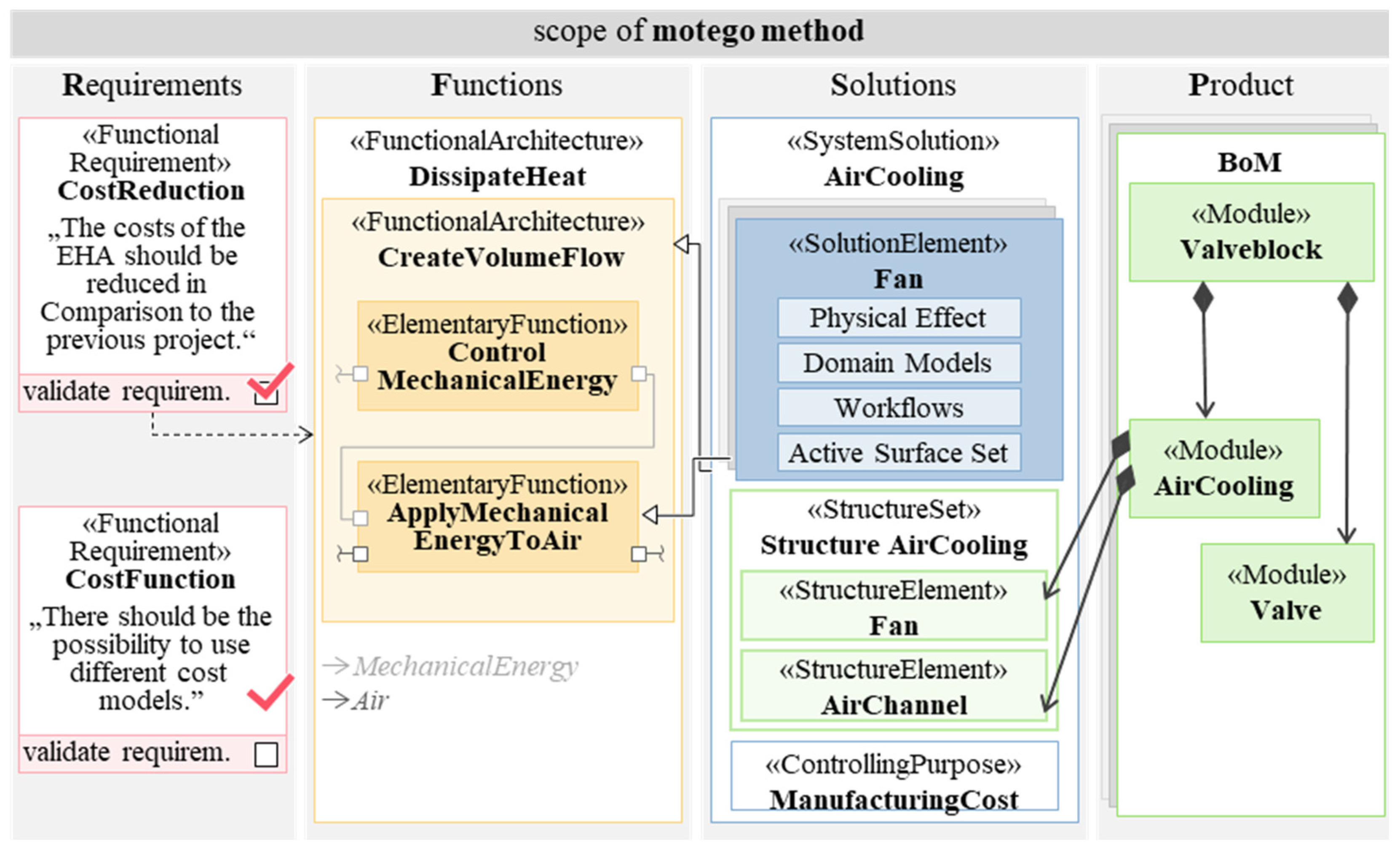
In this section, the methodical parts are shown in detail. Firstly, the cost types are used to implement a custom rollup pattern; secondly, the product elements are given the specified rollup pattern; and lastly, it is shown how the values for the cost parameters are calculated. As the motego method is used, a short introduction is made. The motego method is a Requirements Functions Logic Product (RFLP) based product development method. As in the motego method, the Logic is represented by so-called solutions, the abbreviation becomes RFSP. Inherently, all four RFSP sections of the product are modeled in the system model. The SysML Blocks used to represent the elements are marked with the respective section. As this contribution focuses on the cost of parts and assemblies of the product, it is mostly situated in the Product section of the system model. Other elements are generally not shown for the sake of visibility. As the cost calculation approach presented in this contribution should work with all SyML-based MBSE methods, only the necessary elements from the motego method are given in the respective sections of the contribution. The following Figure 2 shows an example of all four RFSP sections [24,26,27,28,29].
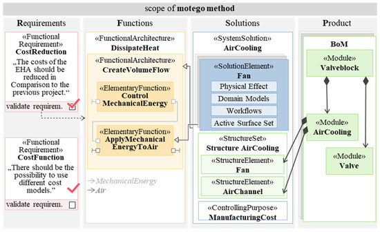
Figure 2.
The motego method in reference to [24].
3.1.1. Implementing a Rollup Pattern for Cost Calculation
Based on the product cost aggregation from Figure 1 and the models of Weustink et al. [4] and Van der Laan et al. [22], the cost types for different elements of a product can be derived. For a manufactured part, these are manufacturing and material costs. For a bought part or assembly, the cost type is the purchase cost. For assemblies that are not bought, the assembly cost is the cost type to be considered. To separate the raw material cost for the manufacturing (e.g., steel for milling) and the cost for bought-in parts (e.g., a motor or a valve), a distinction between material cost and purchase cost is made later on. This results in the allocation shown in Table 1 and later Table 2 [3,4,19,22,23,30,31,32,33].

Table 1.
Used cost calculations per element of a product.
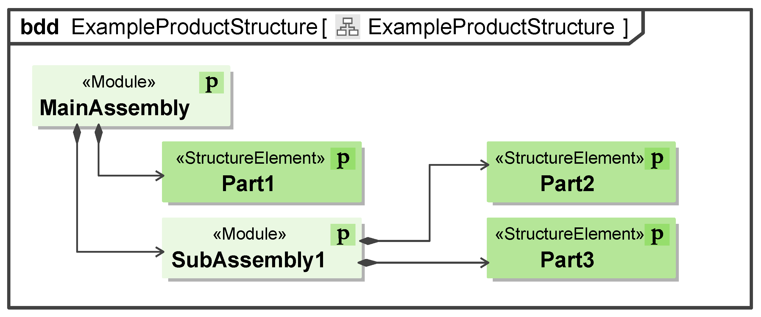
In the motego method, the physical elements are represented by the stereotypes «StructureElement» and «Module» for parts and assemblies, respectively. These stereotypes are derived from the stereotype «Block» of SysML. For representing an assembly structure, the respective blocks are connected by a directed composition. A generic example of this hierarchy is shown in Figure 3. The information from Table 1 is distributed over this hierarchy. As the elements are from the “product” section of the MBSE methodology, they have the symbol “P” in the corner of the block.
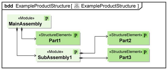
Figure 3.
Example product structure of the motego methodology.
For the calculation of values distributed over a SysML hierarchy, the tool Cameo Systems Modeler already has a mechanism implemented: rollup patterns. With this mechanism, it is possible to generate a custom formula and calculate this formula in a hierarchical system. This is achieved by calculating the formula for all the child blocks separately and passing the results to the parent block. In the parent block, the formula is also calculated for this block. Subsequently, the results of the children and the parents are added up and give the result for the whole structure. This generic equation structure is shown in Equation (1).
Total = parent + sum(child)
A drawback of the rollup pattern is that the same formula is applied to all blocks in the hierarchy and, as such, cannot differentiate between part and assembly. As such, a general formula for the product cost calculation, which includes all cost types that can apply to a physical element in the product, needs to be found.
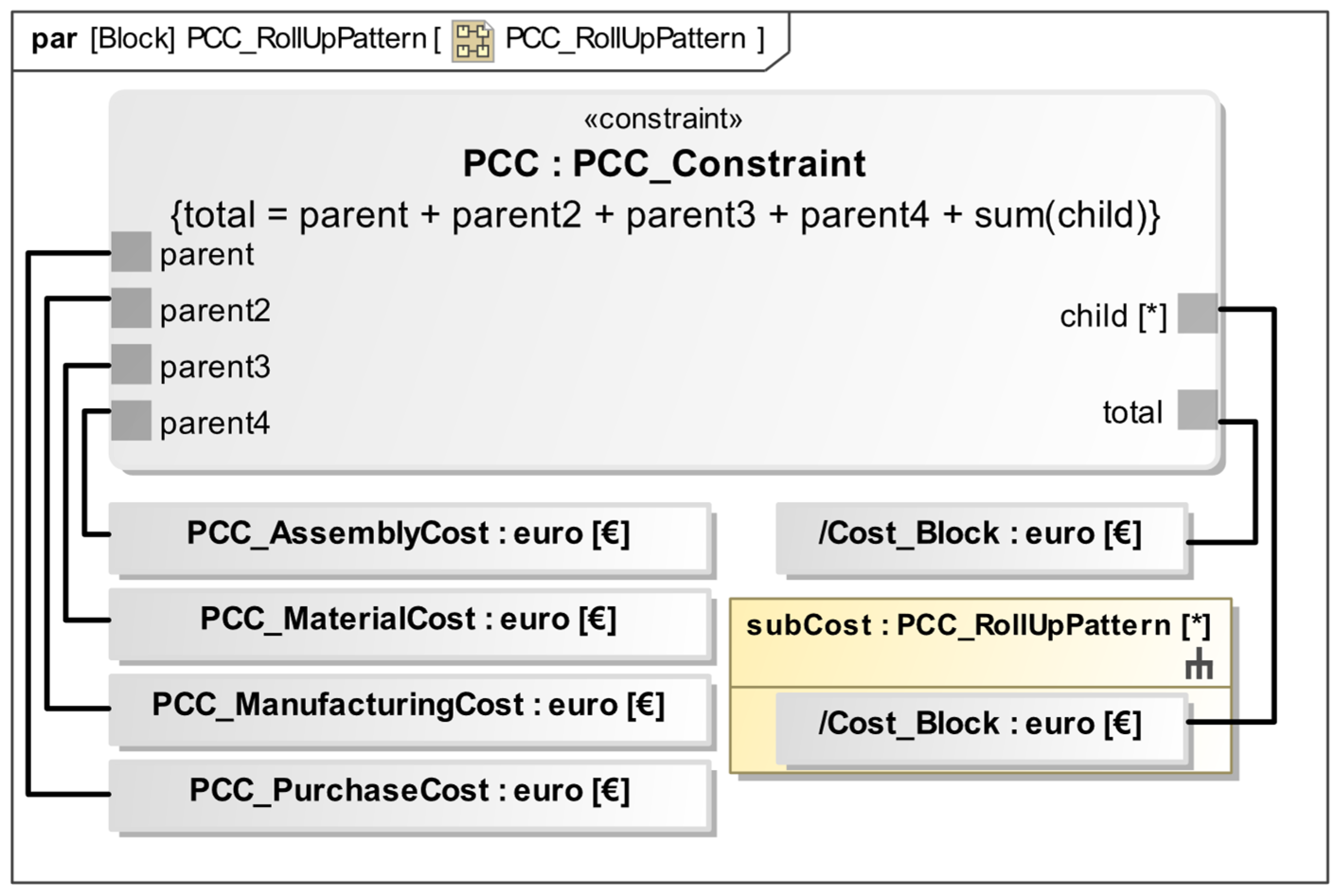
As the cost types derived are specific to an assembly or part (Table 1), the rollup pattern can only calculate a non-specific formula if all the cost types are given to every block part or assembly. This leads to a specific formula for a block given in Equation (2). This formula can then be put in the same scheme as Equation (1) and implemented into a rollup pattern in SysML.
Cost_(Block) = PCCAssemblyCost + PCC_PurchaseCost + PCC_MaterialCost + PCC_ManufacturingCost
The implementation of this product cost calculation (PCC) is shown in Figure 4. The equation at the top of the constraint block is the corresponding equation to Equation (1). The elements for the parent are given in Equation (2). The implementation is carried out in Cameo Systems Modeler 2019.
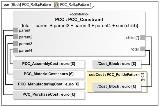
Figure 4.
Definition of the Rollup pattern used for the cost calculation.
During the use of the rollup pattern, not every parameter from the formula will have a value, e.g., the manufacturing cost will have no value for purchased parts. These unused values need to be set to zero, as the formula cannot calculate with empty values. To simplify the usage of the rollup patterns, the zero value is set already in the formula of the rollup pattern itself. Doing this eliminates the need for the user of the rollup pattern to fill in the zero value during the usage of the rollup pattern. Thus, the modeling effort for all unused parameters is reduced.
For the modeling of the connection between a model output and a rollup pattern input, an extra step is necessary because, in Cameo Systems Modeler, in some cases, the output of the model is overwritten by the default value zero if this direction is not explicitly given. As such, another constraint is necessary to enforce the direction of information flow from the model into the roll-up pattern. This second constraint contains only the formula output of the constraint is equal to the input of the constraint, and is named Directed Equals (DirEq). The formula forces Cameo Systems Modeler to write the output of the calculation model into the parameter of the roll-up pattern. The implementation is shown later in this contribution. As the rollup pattern can now be applied, the example structure from Figure 3 with the applied rollup pattern is shown in Figure 5. The values are all set to zero by default. The usage with values is shown in Section 3.2.
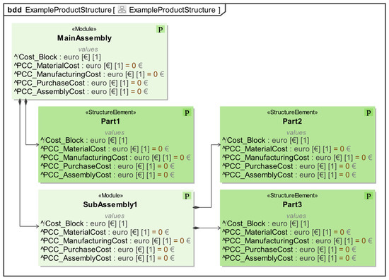
Figure 5.
Applied rollup pattern to the example structure.
3.1.2. Calculating the Values for the Cost Types
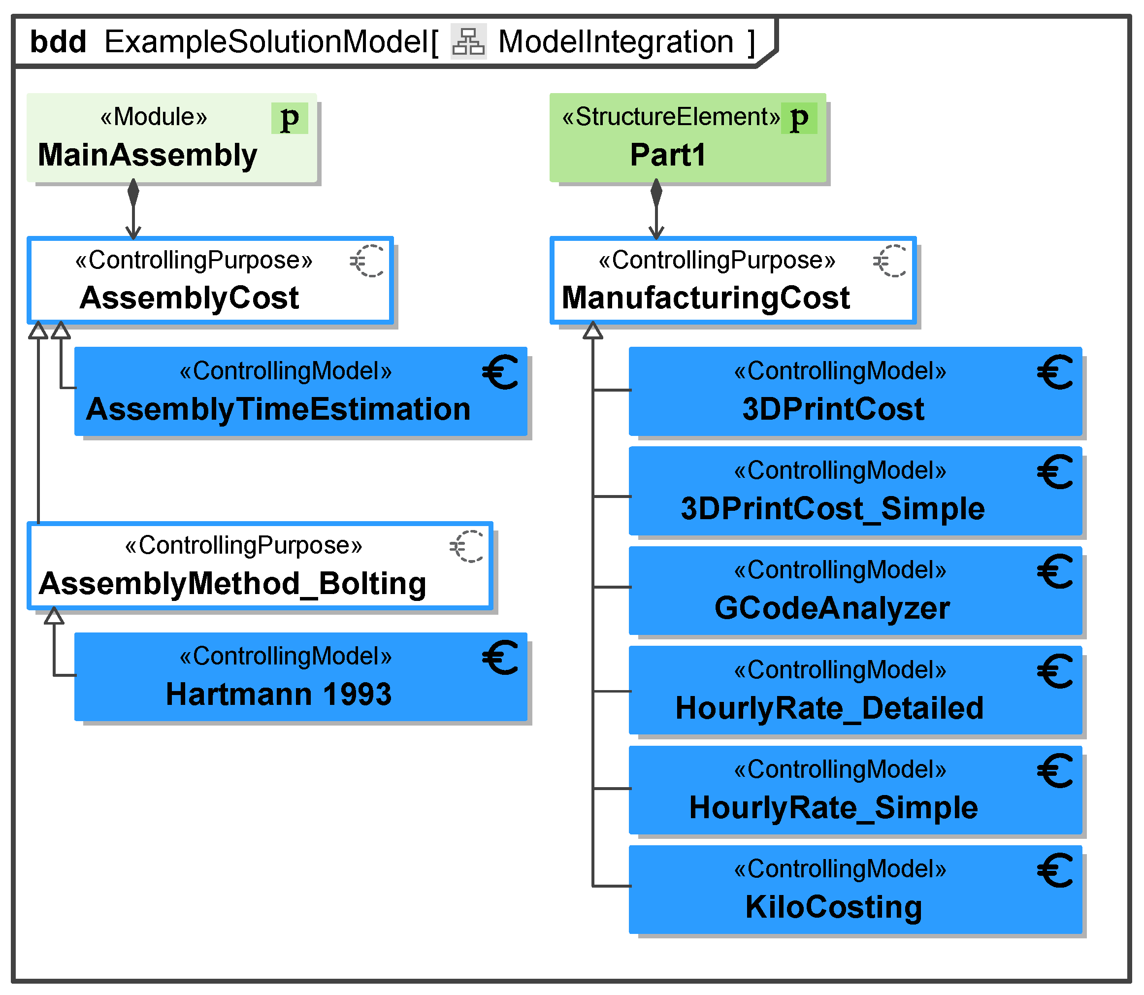
With the rollup pattern, the parameters for the cost types are defined; the specific values now need to be obtained to calculate the product cost. As the goal of this contribution is to show the calculation in MBSE, calculation models are used for manufacturing costs and assembly costs. The mathematical approaches of these models are already known and shown in different publications, which are shown for each respective model later in the contribution. These models were implemented as part of this contribution and are shown in Figure 6. The needed models are specific for the part type under consideration, which are shown in Table 2.
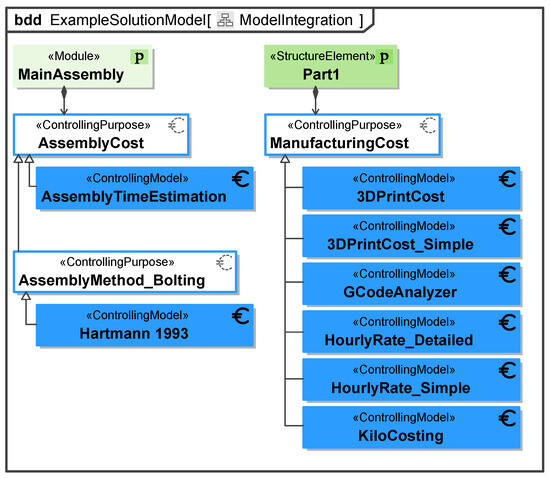
Figure 6.
Implemented purpose and models for manufacturing component and assembly.
Table 2.
Used cost calculations per part type.
Table 2.
Used cost calculations per part type.
| Part Type | Cost Types to Be Considered | Calculation Method | Sources |
|---|---|---|---|
| Buy in part | Price of the part | Value given by the receipt | |
| Manufacturing part | Material cost | Material price | [17,34] |
| manufacturing cost | Manufacturing cost models | ||
| Assemblies | Assembly cost | Assembly cost models | [19,23] |
To achieve the goal of interchangeable calculation models, the approach of model classification is used [16]. In this approach, a model is not directly connected to the element that is used for, e.g., a «SolutionElement» or «StructureElement». Here, a so-called purpose is a level of abstraction between the model and the element. In Figure 6, an example of this approach is shown. The model for cost calculation (for example, the 3DPrintCost model) is not directly connected to the element, in this example, the «StructureElement» Part1. The purpose ManufacturingCost is connected in-between with a directed composition to the part and a generalization to the models. As such, the information, e.g., estimated manufacturing time or part weight from the «StructureElement» is available for the purpose. By a generalization, this information is given to every model connected to this purpose, in Figure 6, for example, the model 3DPrintCost_Simple. The specific cost calculation model will be chosen when the cost calculation for the «StructureElement» is started. Inherent to cost calculation is an uncertainty in the result of the calculation, especially in the early phases of the PDP. This contribution does not omit this uncertainty, but due to the interchangeability of the models gives a possibility to change the calculation model to a more precise alternative, if the information for the more precise model is available. This also means, the cost calculation will become more precise over time, if the information is present as well as correct, and models are changed accordingly.
For assembly cost models, the purpose and model approach can be extended by the generalization of purposes, also shown in Figure 6. There are general assembly cost models (e.g., [17]) and specific cost models (e.g., [19]). The specific models are dependent on the assembly method, e.g., the bolt connection has a vastly different model than a welding model, yet some input and output parameters, e.g., assembly time and costs, are the same. For this contribution, a small library of openly available cost models is implemented with the motego method. These are shown in Figure 6. This library has no claim to completeness but serves as an example for the contribution and will be extended over time.
The models AssemblyTimeEstimation and HourlyRate_Simple, as well as the model HourlyRate_Detailed, are based on formulas given in [17]. The models 3DPrintCost_simple, 3DPrintCost, and CGodeAnalyzer are specified calculations of the machine hour rate for a fused deposition 3D printer. The model KiloCosting is based on a rule of thumb calculation, which calculates the cost of a part based on its weight. For example: A kilogram of cast iron with some post processing costs 1.25 € per kilogram, so a part weighing 4 kg will cost 5 €. The values for this type of calculation are seldom published and specific to a company, like in [34]. The model Hartmann 1993 is an assembly cost model for a bolt connection based on the number of bolts, the length of the bolts, and the tightening torque [19]. A list of the models with classification by scope, purpose, and fidelity is shown in Table 3. The classification for fidelity is carried out by high fidelity, meaning the most accurate, and low fidelity the most general results of the models.
Table 3.
Used cost calculation models with classification by scope, purpose, and fidelity.
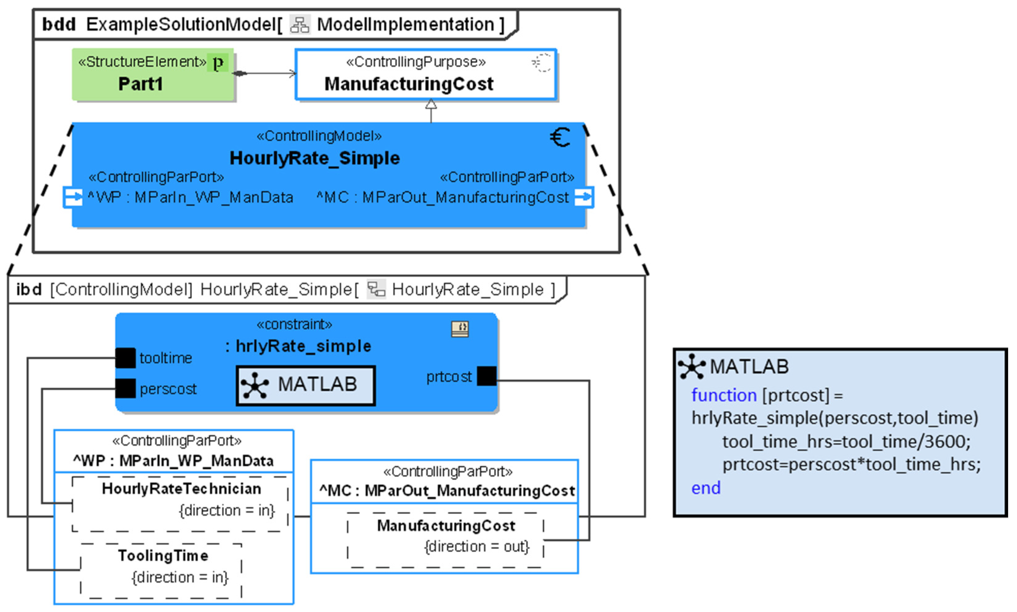
For an exemplary integration, the model of a simple time estimation is shown in Figure 7. In the upper part, the block definition diagram (bdd) gives the connection between the part, purpose, and model, with the used ports displayed in the model. In the internal block diagram (ibd) of the model, the constraint is displayed. The information for the model is passed from the «StructureElement» via full ports and flows into the constraint. The information is then passed to the MATLAB interface for Cameo Systems Modeler. The used MATLAB code is written in version R2023b also given in the third part of the figure. MATLAB is a platform for numerical calculation and programming [35]. It is chosen here, as it is widely spread for executing calculations and has a direct integration into CSM [35].

Figure 7.
Implemented time estimation calculation.
For the model, the needed information is given to the «ControllingPar-Port» for Manufacturing Parameters Input, in this Work Preparation Manufacturing Data (MParIn_WP_ManData). In the port, the information is passed through by the included flows. In this case, the hourly rate in euros per hour and the tooling time in seconds. The MATLAB code then calculates the manufacturing costs (prtcost). As the tooling time is in seconds and the hourly rate is based on hours, a conversion is needed. The part cost from the MATLAB code is then given to the output flow in the «ControllingParPort» Manufacturing Parameter Output (MParOut_ManufacturingCost).
3.1.3. Using Templates to Facilitate Model-Based Cost Calculation in the Product Structure
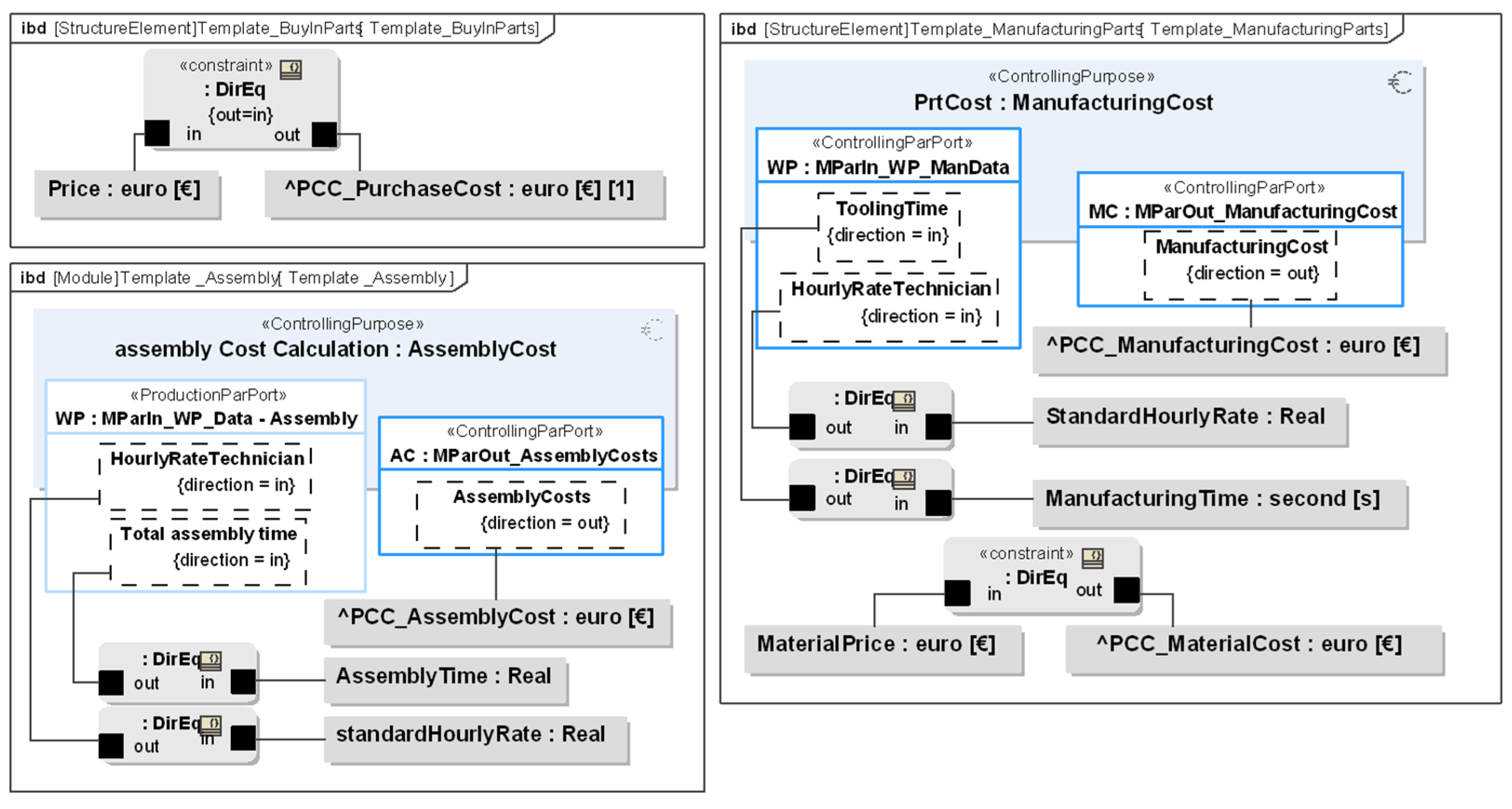
For the development of the given method, one goal is to derive a fast and efficient way to use the integrated cost models and rollup patterns. To achieve this, multiple templates were designed to model products in the system model. As in the method presented in this contribution, the product cost is calculated with the block for the part or assembly, the model purpose, and the already applied rollup pattern, the template should consist of these elements. The template is built for a buy-in part, a manufacturing part, and an assembly, respectively. The resulting templates are shown in Figure 8 as ibd.

Figure 8.
Templates for the buy-in part, manufacturing part, and assembly.
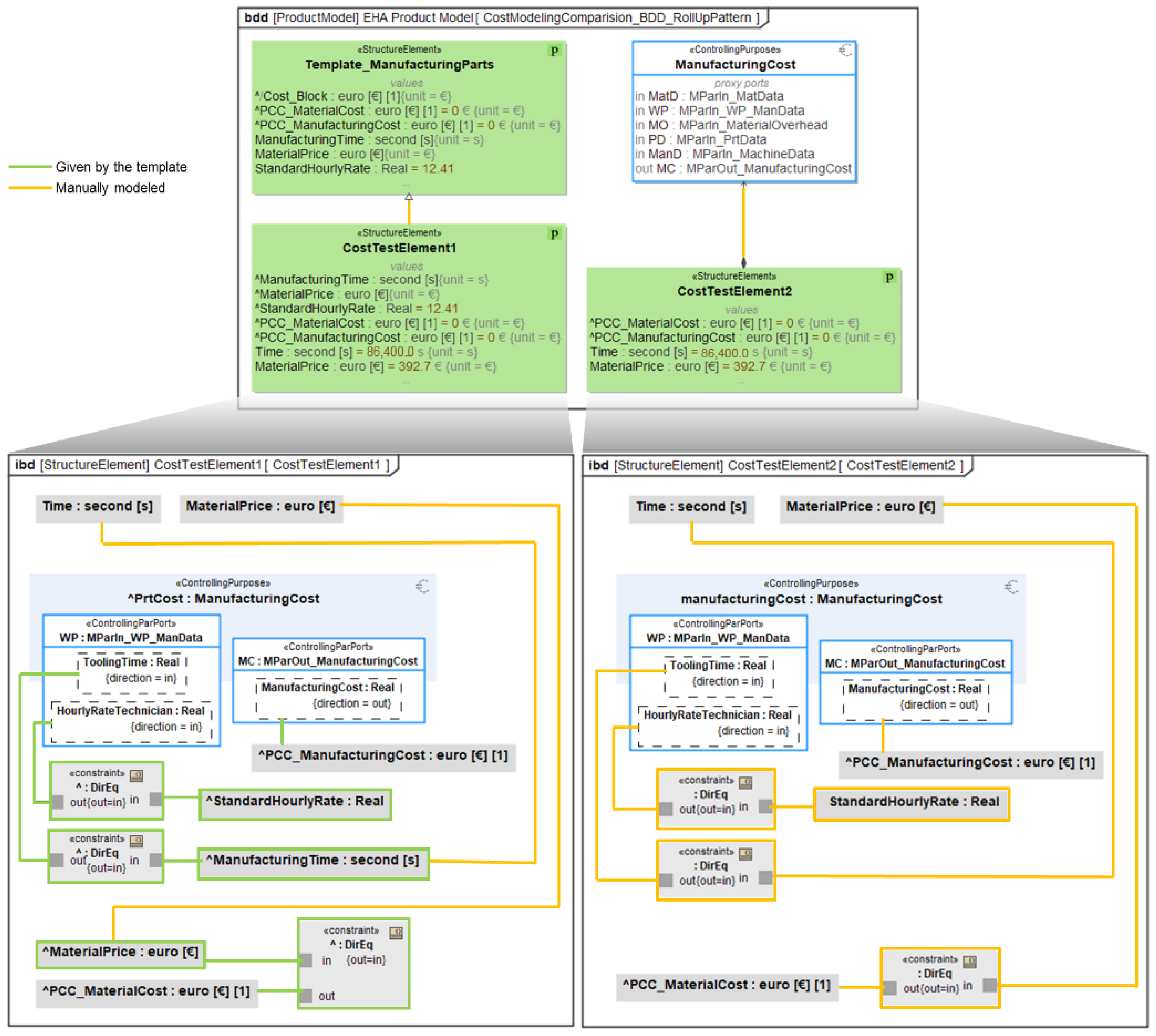
The modeling effort can be measured by the number of connections that need to be modeled when adding a new part. Therefore, a comparison between adding a part without using the template and using the template is made. This is represented in a visual way for two Elements: CostTestElement1 with a template and CostTestElement2 without a template in Figure 9. Here, the connections that are already given by the template are marked in green. The connections and elements that need to be modeled are marked in orange.
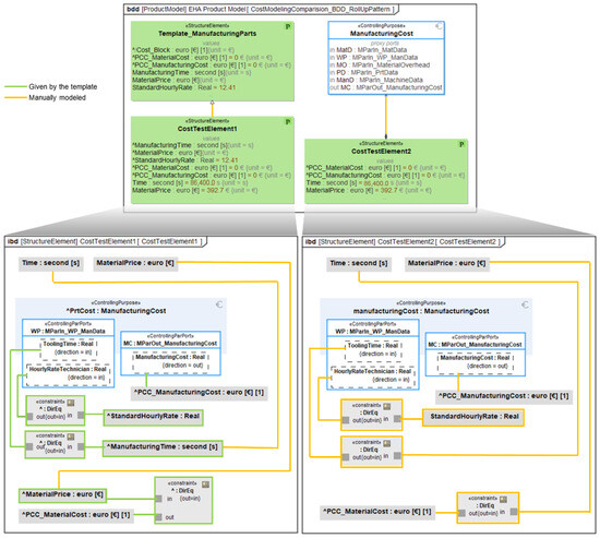
Figure 9.
Modeling of CostTestElement1 with and CostTestElement2 without a template.
If a new part is added to the system model, without using the template, first the rollup pattern needs to be applied, then the purpose needs to be connected, as well as all the ports of the model. Then, all values of the part need to be connected to the model as well as the result of the model to the rollup pattern. For the manufacturing part, this results in eight connections and three constraints, which need to be modeled.
On the contrary, when using a template, only the generalization needs to be applied, as well as values of the block need to be given to the already existing purpose and rollup pattern structure. For the manufacturing part, this results in only three connections that need to be modeled.
The usage of the template has one small flaw. The values of the rollup pattern are applied, but the parent–child connection of the rollup patterns is broken when two blocks, that have the template, are connected to each other. This is due to the way Cameo Systems Modeler applies the roll-up pattern, and as such, a tool problem. To circumvent this and reconnect the parent and child blocks, the rollup pattern needs to be applied again to these blocks, thus slightly reducing the efficiency of the use of templates for rollup patterns. While the rollup pattern needs to be reapplied, the connections between values of the block and the values of the rollup pattern will stay, e.g., the connection of the output of a model to the cost type of the rollup pattern.
Thus, the modeling effort for using the template needs one extra step: reapplying the rollup pattern. The modeling effort difference is six connections and two constraints without the template, and three connections and the reapplication of the rollup pattern with the template for every part of the modeled product. Depending on the modeling capabilities of the person, this results in around 35 s for the modeling without a template and 15 s with the template, thus resulting in a time difference of 20 s per part. For one singular part, this is not a significant increase in time, but for a whole assembly consisting of two hundred elements, the templates reduce the estimated modeling time from 7000 s to 3000 s. As such, the modeling with templates makes the modeling faster in the whole assembly.
The templates only account for the cost calculation aspect. As such, only cost-specific parameters are added if the template is applied.
From the templates and the small model library, an importable model is created. This way, the templates and the models with all connections can be imported into the system model of the product and used there. If multiple products are developed, they use the same library everywhere. This also means that in a corporate environment, the library can be centralized and managed, while all product development teams use the library.
3.2. Usage of the Cost Calculation in a Project Environment
In the project “Dezentrale Hydraulik II” [36,37], a system model is used for the development of an electro-hydraulic actuator (EHA). Based on this system model, the proposed method is applied exemplarily. In Figure 10 the CAD rendering of the EHA is shown with the corresponding blocks of the system model, with a similar structure to Figure 5. In Figure 10, the Part PRT_ValveBlockBody is shown completely, but for the sake of visibility, not every modeled part of the system model is shown, and only the relevant parameters are displayed for the template.
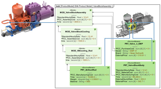
Figure 10.
Overview of the used assembly and parts in the example.
For this example, the valve block assembly (Figure 10, left in orange) with the elements valve (Figure 10, right in red), air duct (Figure 10, right in yellow), and valve block body (Figure 10, right in green) are considered. These represent a buy-in part, two manufacturing parts (both abbreviated as PRT for part), and an assembly (module, MOD), respectively. The values for prices are fictional, but in the same order of magnitude as current market prices. In this stage, the parameters of the rollup pattern are still at the default zero value, as shown in the PRT_ValveBlockBody in Figure 10.
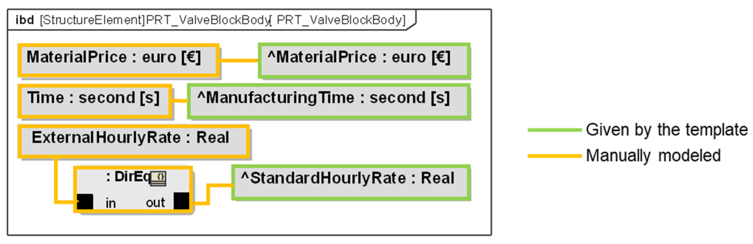
By using the templates, the modeling effort is reduced by around 20 s per part. For the cost modeling using the model HourlyRateSimple, the internal modeling of the valve block is shown in Figure 11. The values of the valve block parameters MaterialPrice and Time are given to the parameters ^MaterialPrice and ^ManufacturingTime from the template. In this example, it is also shown how to use a different value than the standard in the parameter. Here, the ^standardHourlyRate is overwritten by an external Hourly Rate, by a constraint. The modeling for the other parts happens accordingly.
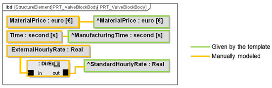
Figure 11.
Modeling of the valve block body.
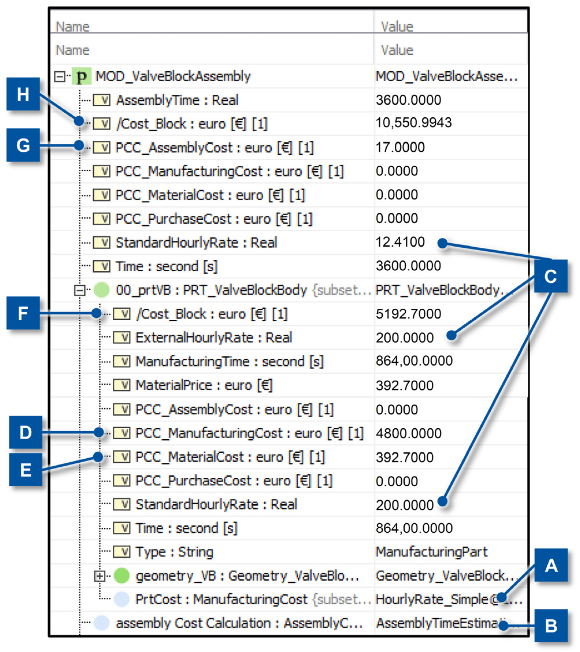
To realize the cost calculation in Cameo Systems Modeler, a simulation can be run for the highest block in the hierarchy, in this example, the module MOD_ValveBlockAssembly. After starting the calculation by the simulation of the highest block, some steps are necessary. For the buy-in parts, no steps are necessary. For the manufacturing parts and assemblies, the only necessary thing to do is to choose the models to be used for the cost calculation. Exemplary, the calculation results of the valve block assembly and the included valve block body are shown in Figure 12. For the sake of visibility, not every part is displayed. At points A and B in Figure 12, the models (HourlyRate_Simple and AssemblyTimeEstimation) are set for the purposes of manufacturing cost and assembly cost. Also, for the part cost of the valve block, the hourly rate has been overwritten (C) as implemented in Figure 11.
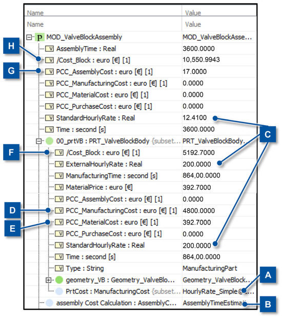
Figure 12.
Results of the cost calculation simulation for the valve block assembly.
For the PRT_ValveBlockBody, the cost model calculates the manufacturing cost to 4800.00 € (D), the material cost for the valve block is 392.70 € (E). As such, the rollup pattern calculates, like in Equation (3), the/Cost_Block to 5192.70 € (F). For the PRT_Valve_3_EMP shown in Figure 10, the/Cost_Block is the external price. For the MOD_ValveBlockAssembly, the cost model calculates an assembly cost of 17.00 € (G). The value for/Cost_Block of the valve block assembly is the sum of every parameter/Cost_Block of its children, e.g., the two valves and the PRT_ValveBlockBody. The resulting calculation gives a cost of 10,550.99 € (H) for the MOD_ValveBlockAssembly. The valve block itself makes up around half of these costs.
For further exemplary explanation of the application of the method, two additional scenarios are considered in the following to show the interchangeability of models and the connection of the models to the technical parameters of the parts, as stated in the requirements in the introduction.
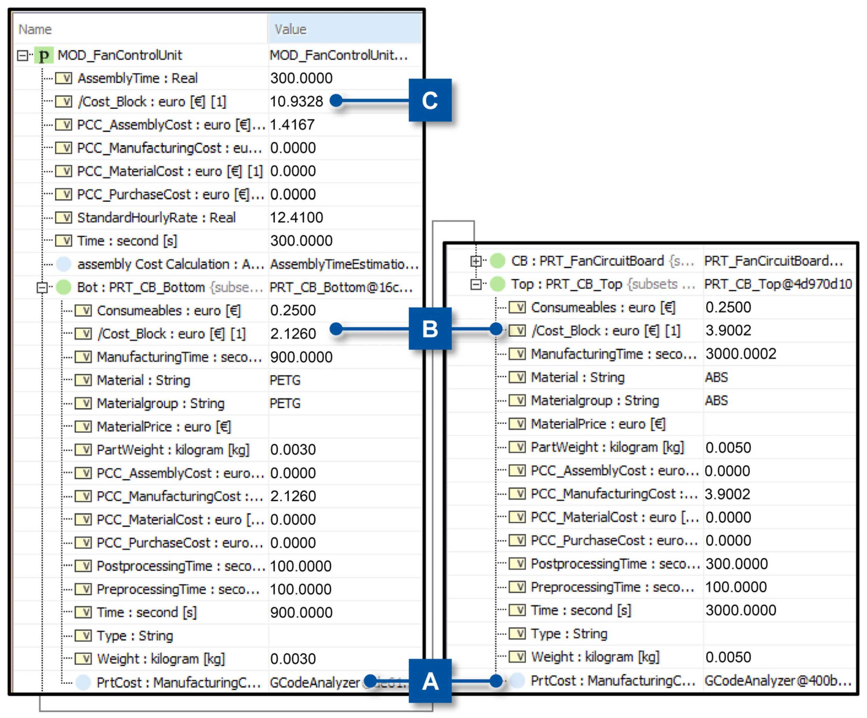
The first scenario is the use of a more detailed manufacturing cost model, in exchange for the standard template model, as would happen in a later phase of the PDP. The second scenario is the change in value of a technical parameter in the assembly, and consequently, the updated calculation of the costs. For both scenarios, the assembly MOD_FanControlUnit is considered as it is small, and the changes are visible as no parameters are hidden in the figures. The CAD assembly, as well as the modeling and an initial cost calculation on which both scenarios are based, are shown in Figure 13. The cost calculation result is shown in two columns. In the figure, the structure of the rollup pattern is visible. As stated in Equation (1), the cost is calculated by the structure of the parent, added to the sum of the children. In this case, the value for/Cost_Block from the module (Figure 13, A) is the sum of the PCC Parameters from the module (Figure 13, B) as well as the sum of the parameter/Cost_Block from PRT_CB_TOP, PRT_CB_BOTTOM and PRT_FanCircuitBoard, (Figure 13, C, D, E, respectively) which is represented in Equation (3).
5.7336 =/Cost_Block = 1.4167 + sum(0.2678 + 3.4900 + 6.5592)
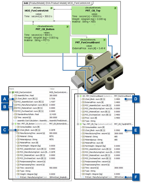
Figure 13.
Fan Control unit: Modeling, CAD-assembly, and cost calculation.
For the first scenario, the model 3DPrintCost_Simple is changed to the model GCodeAnalyzer. For this, the last field (Figure 13, F) of the two columns needs to be changed to the respective model, which is already implemented into the template. Changing the Field is conducted by a right click and adding the model. When simulating again, the new model is used. The first model can calculate a price based on an estimated time value, the material, and the estimated weight of the part. The second, more detailed model will take the necessary information from the machine code for the 3D printer (GCODE) that is used to manufacture the part itself, and considers the pre- and post-processing times for the manufacturing. The results of this detailed calculation are shown in Figure 14. Here, the PRT_FanCircuitBoard is not extended, as it stays the same during the changes in the scenarios. In Figure 14, the model changed to the more detailed model. At Figure 14, B consequently the cost for the parts has changed, and the parameter/Cost_Block at Figure 14, C. Due to the change in model granularity, the cost differs between before (5.7336 €, Figure 13) and after (10.9328 €, Figure 14, C).

Figure 14.
Scenario 1: Cost calculation results for the fan control unit with the GCODE analyzing cost model.
For the second scenario, two engineering changes are made to the assembly. Firstly, the material for the part PRT_CB_Top is changed from ABS to PETG (Figure 15, A). Secondly, the wall thickness is changed in CAD. For this case, it results in a different GCODE of the parts and, as such, different costs for the product (Figure 15, B). As there are no changes to PRT_CB_Bottom, its tree is shown minimized.
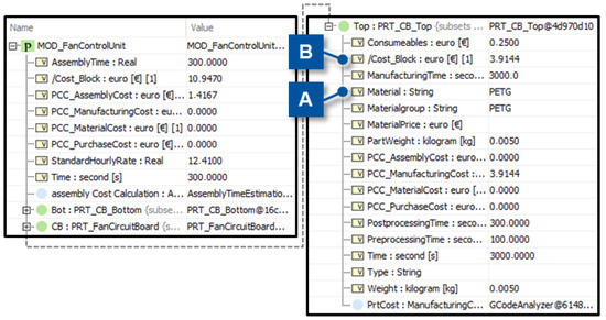
Figure 15.
Scenario 2: Cost calculation results for the fan control unit with GCODE analyzing cost mode.
From these two scenarios, one can see that models of different granularity can be changed with minimal effort, as well as that engineering changes lead directly to an updated product cost in the system model.
4. Discussion
In this contribution, a method for calculating the product cost based on technical parameters was developed. The method can be used from the first cost estimation until a detailed cost model and bases on three key components: The aggregation of the singular costs of the product elements to the product cost (1), the calculation of the specific cost for an element of the product based on the type of element with interchangeable cost models (2) and the use of templates in the MBSE method mote-go for a fast and efficient modeling and calculation in the system model of the product (3). The applicability of the developed method is shown for an electro-hydraulic actuator as an exemplary product.
Firstly, the aggregation of the element cost to the product cost (1) was achieved by the development of a specialized rollup pattern. With this rollup pattern, the product cost is automatically updated if the cost of an element changes. The cost model implementation for manufacturing and assembly cost models was explained (2). To show the interchangeability, a small library of common cost models was implemented.
Secondly, the rollup pattern and the cost model library were then connected by the implementation of templates (3) for different types of parts. With these templates, the modeling effort for the use of the cost models was halved, based on the number of connections that need to be modeled for an element for which the cost is to be calculated.
Thirdly, the method was validated by the cost calculation for the valve block assembly of the electro-hydraulic actuator of the project “Dezentrale Hydraulik II”. Here, the interchangeability of the models and the cost change based on the change in a technical parameter was confirmed. Therefore, this approach enables the use of a simple model in an early stage of the PDP, when not much information is known. It is also possible to change the used model to a very specific calculation when more information is present, while limited remodeling is necessary. As such, the requirements presented at the beginning of this contribution are fulfilled.
In the future, the method can be further expanded in four main fields of action. The first one addresses the usability of the method. Now, the model selection is still manual. Automation can be beneficial here to achieve a more automated use, e.g., selecting the model with the highest accuracy based on available parameters. The second element addresses the models used in the approach. Here, the small library used in this contribution can be greatly expanded by models already existing, or a connection to existing cost calculation software can be implemented. The third element addresses the usage and visualization of the calculated data. Now the method is based on the output of Cameo Systems Modeler’s simulation. This can be improved by an output analysis and visualization method. For the use in a specified environment, e.g., a company with specified models, the formula for the rollup pattern can be customized to the company’s needs.
Author Contributions
Conceptualization, G.H., K.B., C.H. and S.S.; Data curation, G.H., L.D., C.H. and S.S.; Formal analysis, G.H., L.D., C.H. and S.S.; Funding acquisition, T.Z. and K.B.; Investigation, G.H., L.D., C.H. and S.S.; Methodology, G.H., L.D. and K.B.; Project administration, G.H. and T.Z.; Resources, G.H., L.D., C.H. and S.S.; Software, G.H., L.D., C.H. and S.S.; Supervision, T.Z.; Validation, G.H., L.D. and K.B.; Visualization, G.H. and L.D.; Writing—original draft, G.H. and L.D.; Writing—review and editing, T.Z. and K.B. All authors have read and agreed to the published version of the manuscript.
Funding
This research was funded by the Federal Ministry for Economic Affairs and Climate Protection based on a resolution of the German Bundestag (IGF-project Nr.: 22246 N).
Data Availability Statement
Data are contained within the article.
Conflicts of Interest
On behalf of all authors, the corresponding author states that there is no conflict of interest. The funders had no role in the design of the study; in the collection, analyses, or interpretation of data; in the writing of the manuscript; or in the decision to publish the results.
Abbreviations
The following abbreviations are used in this manuscript:
| ABS | Acrylnitril-Butadien Styrene |
| Bdd | Block Definition Diagram |
| CAD | Computer-Aided Design |
| CSM | Cameo Systems Modeler |
| DirEq | Directed Equals |
| EHA | Electro-hydraulic Actuator |
| Ibd | Internal Block Diagram |
| IGF | Industrielle Gemeinschaftsforschung |
| MBSE | Model-based Systems Engineering |
| MDPI | Multidisciplinary Digital Publishing Institute |
| MOD | Module |
| MSE | Institute for Machine Elements and Systems Engineering |
| PCC | Product Cost Calculation |
| PDP | Product Development Process |
| PETG | Polyethylenterephthalat |
| PRT | Part |
| SPOT | Single Point of Truth |
| SysML | Systems Modeling Language |
References
- VDI Verein Deutscher Ingenieure e.V.; VDI—The Association of German Engineers. Wirtschaftliche Entscheidungen beim Konstruieren: Methoden und Hilfen, 00.1987, 21.020 Kennwerte und Konstruktion von Maschinen, Geräten und Betriebsmitteln. Available online: https://nautos.de/7TE/search/item-detail/DE18703451 (accessed on 9 August 2024).
- Eigner, M.; Stelzer, R. Product Lifecycle Management: Ein Leitfaden für Product Development und Life Cycle Management; 2., neu bearb. Aufl.; Springer: Berlin/Heidelberg, Germany, 2009; ISBN 978-3-540-44373-5. [Google Scholar]
- Loyer, J.-L.; Henriques, E. 2.3.1 A MBSE probabilistic framework for preliminary lifecycle costing of mechanical products. INCOSE Int. Symp. 2014, 24, 182–195. [Google Scholar] [CrossRef]
- Weustink, I.; ten Brinke, E.; Streppel, A.; Kals, H. A generic framework for cost estimation and cost control in product design. J. Mater. Process. Technol. 2000, 103, 141–148. [Google Scholar] [CrossRef]
- Panko, R. Thinking is Bad: Implications of Human Error Research for Spreadsheet Research and Practice. arXiv 2008, arXiv:0801.3114. [Google Scholar]
- Panko, R. Spreadsheet Errors: What We Know. What We Think We Can Do. arXiv 2008, arXiv:0802.3457. [Google Scholar]
- Ehrlenspiel, K.; Kiewert, A.; Mörtl, M.; Lindemann, U. Kostengünstig Entwickeln und Konstruieren: Kostenmanagement bei der Integrierten Produktentwicklung; 8. Auflage; Springer Vieweg: Berlin/Heidelberg, Germany, 2020; ISBN 978-3-662-62590-3. [Google Scholar]
- Eigner, M.; Roubanov, D.; Zafirov, R. Modellbasierte Virtuelle Produktentwicklung; Springer: Berlin/Heidelberg, Germany, 2014. [Google Scholar]
- Casse, O. (Ed.) SysML: Object Management Group (OMG) Systems Modeling Language. In SysML in Action with Cameo Systems Modeler; ISTE Press Ltd.: London, UK, 2017; pp. 1–63. ISBN 9781785481710. [Google Scholar]
- Delligatti, L. SysML Distilled: A Brief Guide to the Systems Modeling Language; Addison-Wesley: Upper Saddle River, NJ, USA, 2014; ISBN 9780133430356. [Google Scholar]
- Krause, D.; Heyden, E. (Eds.) Design Methodology for Future Products: Data Driven, Agile and Flexible; Springer: Cham, Germany, 2021; ISBN 978-3-030-78367-9. [Google Scholar]
- Ehrlenspiel, K. Kostengünstig Entwickeln und Konstruieren: Kostenmanagement bei der Integrierten Produktentwicklung, 7th ed.; Springer: Dordrecht, The Netherlands, 2013; ISBN 978-3-642-41958-4. [Google Scholar]
- Akundi, A.; Lopez, V. A Review on Application of Model Based Systems Engineering to Manufacturing and Production Engineering Systems. Procedia Comput. Sci. 2021, 185, 101–108. [Google Scholar] [CrossRef]
- Dabkowski, M.; Estrada, J.; Reidy, B.; Valerdi, R. Network Science Enabled Cost Estimation in Support of MBSE. Procedia Comput. Sci. 2013, 16, 89–97. [Google Scholar] [CrossRef]
- Bleakley, G.; Lapping, A.; Whitfield, A. 6.6.2 Determining the right solution using SysML and model based systems engineering (MBSE) for trade studies. INCOSE Int. Symp. 2011, 21, 783–795. [Google Scholar] [CrossRef]
- Spütz, K.; Berges, J.; Jacobs, G.; Berroth, J.; Konrad, C. Classification of Simulation Models for the Model-based Design of Plastic-Metal Hybrid Joints. Procedia CIRP 2022, 109, 37–42. [Google Scholar] [CrossRef]
- Schweitzer, M.; Küpper, H.-U.; Friedl, G.; Hofmann, C.; Pedell, B. Systeme der Kosten-und Erlösrechnung; 11., überarbeitete und erweiterte Auflage; Vahlen: München, Germany, 2016; ISBN 978-3-8006-5027-9. [Google Scholar]
- Dewhurst, P.; Boothroyd, G. Early Cost Estimating in Product Design. J. Manuf. Syst. 1988, 7, 183–191. [Google Scholar] [CrossRef]
- Hartmann, M. Entwicklung eines Kostenmodells für die Montage: Ein Hilfsmittel zur Montageanlagenplanung. Ph.D. Thesis, Rheinisch-Westfälische Technische Hochschule Aachen, Aachen, Germany, 1993. [Google Scholar]
- Spütz, K.; Jacobs, G.; Konrad, C.; Wyrwich, C. Integration of Production and Cost Models in Model-Based Product Development. Open J. Soc. Sci. 2021, 9, 53–64. [Google Scholar] [CrossRef]
- Jacobs, G.; Konrad, C.; Berroth, J.; Zerwas, T.; Höpfner, G.; Spütz, K. Function-Oriented Model-Based Product Development. In Design Methodology for Future Products: Data Driven, Agile and Flexible; Krause, D., Heyden, E., Eds.; Springer: Cham, Germany, 2021; pp. 243–263. ISBN 978-3-030-78367-9. [Google Scholar]
- van der Laan, T.; Johman, A.; van Puffelen, T.; Nolet, S.; van Maanen, B.; Daugulis, E.; van den Berg, T. An open source part cost estimation tool for MDO purposes. In Proceedings of the AIAA AVIATION 2021 FORUM, Virtual, 2–6 August 2021; American Institute of Aeronautics and Astronautics: Reston, VA, USA, 2021. [Google Scholar]
- Batarseh, O.; McGinnis, L.; Lorenz, J. 6.5.2 MBSE Supports Manufacturing System Design. INCOSE Int. Symp. 2012, 22, 850–860. [Google Scholar] [CrossRef]
- Wyrwich, C.; Boelsen, K.; Jacobs, G.; Zerwas, T.; Höpfner, G.; Konrad, C.; Berroth, J. Seamless Function-Oriented Mechanical System Architectures and Models. Eng 2024, 5, 301–318. [Google Scholar] [CrossRef]
- Dassault Systèmes. CATIA Magic—Global Model-Based Systems Engineering Solutions. Available online: https://www.3ds.com/products/catia/catia-magic (accessed on 24 March 2025).
- Riedel, R.; Florides, C.; Stein, S.; Spütz, K.; Guerrero, D.A.; Konrad, C. Improving Parameter Traceability in Model-Based Product Development Processes through Integration of Python-Based Domain Models. Procedia CIRP 2023, 119, 539–544. [Google Scholar] [CrossRef]
- Moers, F.; Jacobs, G.; Mennicken, M.; Irnich, L.; Boelsen, K.; Höpfner, G. Reusable solution element libraries for accelerated application of MBSE in mechanical product development. Forsch. Ingenieurwesen 2025, 89, 54. [Google Scholar] [CrossRef]
- Jagla, P.; Jacobs, G.; Spütz, K.; Berroth, J. Classification of function-oriented solution elements for MBSE. Forsch. Ingenieurwesen 2023, 87, 469–477. [Google Scholar] [CrossRef]
- Vereinigung zur Förderung des Instituts für Maschinenelemente und Systementwicklung der Rheinisch-Westfälischen Technischen Hochschule Aachen e.V. Motego: Know your Product. Available online: https://www.motego.info/ (accessed on 23 April 2025).
- Berges, J.M.; van der Straeten, K.; Jacobs, G.; Berroth, J. Towards a Model-Based Approach for the Optimization of the Mechanical and Economical Properties of Laser-Based Plastic-Metal Joints. Key Eng. Mater. 2022, 934, 75–80. [Google Scholar] [CrossRef]
- DIN Deutsches Institut für Normung e.V.; DIN German Institute for Standardization. Berechnungsgrundlagen: Kosteninformationen; Kalkulationsarten und -verfahren, 00.1989, 03.100.60Accountancy. Available online: https://nautos.de/7TE/search/item-detail/DE18905342 (accessed on 7 August 2024).
- DIN Deutsches Institut für Normung e.V.; DIN German Institute for Standardization. Kosteninformationen: Begriffe zu Kosteninformationen in der Maschinenindustrie, 00.1989, 01.040.03Services. Company Organization, Management and Quality. Administration. Transport. Sociology (Vocabularies). Available online: https://nautos.de/7TE/search/item-detail/DE18905341 (accessed on 7 August 2024).
- DIN Deutsches Institut für Normung e.V.; DIN German Institute for Standardization. Berechnungsgrundlagen: Kosteninformationen; verfahren der Kurzkalkulation, 00.1993, 03.100.60Accountancy. Available online: https://nautos.de/7TE/search/item-detail/DE18940839 (accessed on 7 August 2024).
- Rinborn Machinery Co. Estimated Cost of Iron Sand Castings. Available online: https://de.steel-foundry.com/blog/estimated-cost-of-iron-sand-castings/ (accessed on 29 August 2024).
- The MathWorks. MATLAB. Available online: https://de.mathworks.com/products/matlab.html (accessed on 23 April 2025).
- Figge, F.; Schmitz, K. Simulative Comparison Approach of Electro-Hydrostatic Actuator Circuits in Excavators. In Proceedings of the ASME/BATH 2023 Symposium on Fluid Power and Motion Control, Sarasota, FL, USA, 16–18 October 2023. [Google Scholar] [CrossRef]
- Institute for Fluid Power Drives and Systems. Decentralized Hydraulics II—RWTH AACHEN UNIVERSITY IFAS—English. Available online: https://www.ifas.rwth-aachen.de/cms/ifas/forschung/hochleistungskomponenten/~wifxd/dezentrale-hydraulik-ii/?lidx=1 (accessed on 18 February 2025).


Disclaimer/Publisher’s Note: The statements, opinions and data contained in all publications are solely those of the individual author(s) and contributor(s) and not of MDPI and/or the editor(s). MDPI and/or the editor(s) disclaim responsibility for any injury to people or property resulting from any ideas, methods, instructions or products referred to in the content. |
© 2025 by the authors. Licensee MDPI, Basel, Switzerland. This article is an open access article distributed under the terms and conditions of the Creative Commons Attribution (CC BY) license (https://creativecommons.org/licenses/by/4.0/).