Article

A Fuzzy Logic-Based Automatic Gear-Shifting System for Electric Bicycles in Urban Mobility Solutions for Smart Cities

1
Department of Electrical Engineering, National Taipei University of Technology, Taipei 10608, Taiwan
2
Phoenix Technologies Ltd., Taipei 11494, Taiwan
*
Author to whom correspondence should be addressed.
Systems 2025, 13(4), 228; https://doi.org/10.3390/systems13040228
Submission received: 6 February 2025 / Revised: 12 March 2025 / Accepted: 19 March 2025 / Published: 26 March 2025

Abstract

:
In smart cities, bicycle-sharing systems have become essential as last-mile transportation solutions, seamlessly integrating into urban mobility networks worldwide. To improve riding efficiency, the development of automatic gear-shifting systems for electric bicycles has gained significant attention. This study presents a novel fuzzy logic controller (FLC) designed to address the challenges of frequent and unstable gear shifts in automatic bicycle transmissions. Unlike traditional systems that rely solely on velocity or cadence as inputs, the proposed FLC incorporates both acceleration and slope data to enhance shifting stability and cadence regulation. By replacing velocity with acceleration and integrating slope information, the system minimizes frequent shifting and improves overall performance. Experimental and simulation results demonstrate that the proposed approach reduces acceleration ripple, stabilizes gear-shifting, and maintains cadence within the desired range, ensuring a smoother and more comfortable riding experience. The proposed approach significantly reduces acceleration ripple by 1 m/s2, maintains target cadence, and aligns gear shifts with design intent, yielding a substantial 20% safety improvement. These advancements offer particular promise for public bicycle-sharing systems, providing a robust and adaptable solution suited to diverse cycling conditions and rider profiles.

1. Introduction

In smart cities, bicycle-sharing systems have become essential as last-mile transportation solutions, seamlessly integrating into urban mobility networks worldwide. To enhance riding efficiency, research on automatic gear-shifting systems for electric bicycles has gained significant attention. The gear-shifting mechanism consists of components such as chains, freewheels, derailleurs, and corresponding control devices. By adjusting the gear through these control devices, riders can maintain an optimal cadence to efficiently transfer power while tackling various terrains. While the flexible adjustment of gear ratios has significantly enhanced the riding experience, there is no definitive guideline for pairing the front and rear gear ratios correctly. Beginners often lack the knowledge to configure gear ratios appropriately, leading to inefficiencies in pedaling and diminished riding experience due to improper gear selection. This challenge has sparked the invention of automatic gear-shifting systems.
One of the pioneers of automatic gear shifting is the Browning transmission [1]. Its controller calculates the optimal cadence by considering variables such as bicycle velocity, hub speed, and crank rotation speed, mapping these to the most suitable and closely matched gear ratio to achieve automatic gear shifting. This design became the prototype for many subsequent automatic gear-shifting mechanisms. In recent years, environmental issues have gained increasing attention, prompting countries to establish environmental standards aimed at reducing carbon emissions from fuel-powered vehicles. This shift has accelerated the transition toward electric vehicles and created new market opportunities for bicycles. In addition to the construction of dedicated bicycle lanes in urban planning, many countries now offer shared bicycles and electric-assisted bicycles as part of rental services. With the rapid advancement of technology, sensors and controllers have been widely integrated into electronic devices and automotive systems. The performance of traditional bicycles has gradually been deemed insufficient. By incorporating various sensors and applying derived dynamic bicycle models, advanced controllers tailored to riders’ needs have been developed.
Research on electric-assisted bicycles includes innovative methods proposed by Abagnale et al. [2], who utilized Hall sensors to measure and experiment with chain tension under different gear ratios. From the measured tension, they calculated the pedaling torque and angular velocity. Based on optimal pedelec torque control (OPTC), they derived a dynamic model between the electric motor and pedaling force. The total output power was obtained by summing the output power of the motor and the pedaling force. This total power was fed back to adjust the assistance force according to the pedaling force, achieving smaller tracking errors and better stability. Lee et al. [3] derived the dynamics of electric-assisted bicycles, setting a target velocity and using fuzzy control to adjust motor power output based on the velocity error and pedaling power. They proposed an adaptive method that, after a learning phase, adjusts the membership functions of pedaling power according to the rider’s characteristics, enabling control tailored to different riders’ pedaling forces. Compared to traditional fuzzy control, the learning-based controller showed significant improvements in reducing velocity fluctuations when encountering changes in slope. Lee et al. [4] built upon the dynamic model from [3], setting a threshold for velocity error. If the error exceeded the threshold, the membership functions for velocity error would be adjusted. Unlike [3], which required a learning period, this method allowed for faster adjustments to the controller, better meeting the needs of the rider. Dai et al. [5], building upon the work of [4], proposed a new FLC architecture by incorporating slope as an additional input, where velocity error, slope, and pedal power were combined for fuzzy rule calculations. The defuzzified output determines the corresponding level of electric assist force. In the literature, evaluation metrics included not only velocity but also acceleration, battery energy consumption, and other comfort and safety indicators, reflecting considerations for rider comfort and safety. Uyar et al. [6] designed an electric assist motor that connects to the front chainring to provide pedaling assistance. They developed separate dynamic models for the DC motor and the bicycle, combining them into a third-order transfer function, which was then converted into state-space representation and simulated in Simulink. Users could input their desired target velocity into the model, with velocity error and acceleration used as inputs. The computed results were output through the electric assist motor. In their simulations, the same parameters were applied to fuzzy PID, fuzzy PI, and fuzzy PD controllers to analyze their respective time-domain performance and control efficiency. Ho et al. [7] used wheel speed, wheel acceleration, motor power, and pedaling power as inputs. They developed a model based on the delay phase as pedaling torque (DPPT) to output appropriate assistance force according to different external resistance factors. This was referred to as compensation for the gap in the pedaling torque (CGPT). Four different control methods for electric assist motors were tested, demonstrating that the proposed method had the lowest motor output and the smallest variation in angular acceleration, making it suitable for commuting and environments with limited power supply.
Most electric-assist bicycles focus solely on controlling the auxiliary motor. However, the primary source of power in a bicycle is pedaling force, which drives the rear wheel through the chainring and chain. If inappropriate gear is used, even starting can become challenging. Therefore, it is essential to prioritize the gear, i.e., the function of the transmission system, to adjust the gear ratio between the front and rear chainrings. Three main types of gear-shifting systems are currently available on the market: The first one is mechanical shifting, which is the most common and traditional form found in bicycles. It relies on a gear shifter pulling a steel cable, which in turn drives the derailleur to adjust the gear ratio. Although this design has a slower shifting process due to the difficulty in precisely controlling the cable tension, it is widely used due to its simple mechanism and low cost. The second approach is electronic shifting; in this system, signals are transmitted electronically, and a microcontroller receives the signals to control a servo motor. The servo motor adjusts the gear using pulse-width modulation (PWM) to achieve electronic shifting. Its advantages include fast and precise gear changes, while its primary drawback is the higher cost. With advances in technology, electronic shifting systems have become increasingly popular and can be modularly installed on different bicycle models. They are highly regarded by professional cyclists and enthusiasts. The third is continuously variable transmission (CVT), this system employs a mechanism connected to the crankshaft to achieve gear changes by altering the gear ratio within the mechanism. It uses closely spaced gear ratios across multiple chainrings to provide smooth transitions, enabling stepless shifting. A well-known example is the NuVinci CVT system designed by Fallbrook Technologies [8], which replaces traditional gears with spheres and springs. The power transmission depends on the contact area of the spheres, mimicking the effect of gear ratio changes to the rear wheel. Another example is custom-designed shifting mechanisms; for example, in [9], a gear-shifting mechanism called eDrive was designed using SolidWorks and embedded in the rear wheel hub. It adjusts gear ratios based on pedaling power, allowing riders to maintain a comfortable pedaling force. However, the initial design was focused on control for low pedaling force and low-speed conditions. Chen et al. [10] aim to minimize gear ratio variations during shifting. However, due to their bulky size, complex structure, and limited gear range, these designs face challenges in becoming mass-produced universal components for regular bicycles. As a result, they are primarily explored in research contexts and are rare in the commercial market.
Due to differences in riding environments, individual physical fitness, and cycling habits, pedaling force and the timing of gear shifting vary among riders. Current studies primarily consider factors such as cadence, pedaling torque, bicycle velocity, and acceleration as the basis for gear-shifting decisions and evaluation metrics, with differing perspectives in various research contexts. There are three main control methods for gear-shifting: The first approach is threshold-based control, this approach sets target values for the controller and compares them with sensor data. For instance, gear shifting is triggered when cadence or velocity exceeds predefined ranges. This approach sets target values for the controller and compares them with sensor data. The authors of [10] designed a shifting mechanism connecting a ring gear to the hub motor and the crankshaft to the planetary carrier. Planetary gears adjust the gear ratio, and when cadence increases, instantaneous acceleration rises, prompting the planetary gears to reduce auxiliary force, achieving CVT. Tandon et al. [11] set the cadence target to 50–60 rpm, with an upshift occurring when it exceeds 60 rpm and a downshift when it falls below 50 rpm. In addition to deriving the bicycle dynamics, the designed circuit maps the feedback voltage to different cadence levels and simulates the controller’s performance in LabVIEW for validation. Rauch et al. [12] recorded data such as cadence and pedaling torque during gear shifting to establish six shifting conditions, including torque and cadence thresholds, as well as rapid changes in torque within a specific timeframe. Simulink data were compared with recorded datasets to evaluate the controller’s alignment with shifting intentions. Savaresi et al. [13] proposed a comfort index targeting novice riders to minimize longitudinal acceleration. Cadence was estimated via rear wheel speed and filtered acceleration data. A 15 min training phase produced data on cadence and acceleration corresponding to gear settings. Gear shifts occurred when acceleration fell below a threshold. Atencio et al. [14] recorded normal riding velocity, cadence, and gear settings. When cadence was high without an increase in velocity, the system shifted up; conversely, when velocity was high without an increase in cadence, the system shifted down. Ay et al. [15] utilized an inertial measurement unit (IMU) to measure slope values and compiled them into an effect coefficient table. The slope values in the table determine the upper and lower limits of cadence and velocity, which are used to decide whether to shift gears. However, the experiment included a limited number of gear ratio combinations, and the cadence was significantly higher compared to other studies, making it less suitable for general riding needs. The second is AI-based gear shifting; recent advancements have leveraged AI to process large sensor datasets for determining optimal gear settings. Lin et al. [16,17] integrated data from velocity, global positioning system (GPS), slope, heart rate, and pedaling power to create datasets. These datasets were split into training and testing sets for random forest (RF) classification to predict gear settings. Shift data were uploaded to the cloud for further optimization. In [17], they expanded routes and applied additional learning models to verify results. The third is fuzzy logic controllers. Fuzzy logic has been extensively applied to map sensor inputs to gear ratios or gear outputs. Lin et al. [18] used cadence and torque as inputs to a fuzzy controller, which mapped five gear ratios as outputs. By comparing the current and calculated gear ratios, shifts were executed only when differences were detected. Tsai et al. [19] proposed Interval Type-II (IT2) fuzzy logic to reduce noise and interference in inputs such as bicycle velocity, torque, and cadence, leading to smoother gear ratio outputs. Lin et al. [20] addressed frequent shifting caused by zero cadence on descents by introducing a virtual cadence derived from wheel speed. A prediction of gear shifting was increased when cadence exceeded acceptable values for a gear. Once the prediction exceeded a threshold, a gear change was triggered, and cadence data were incorporated into membership functions for learning. Bjarkason et al. [
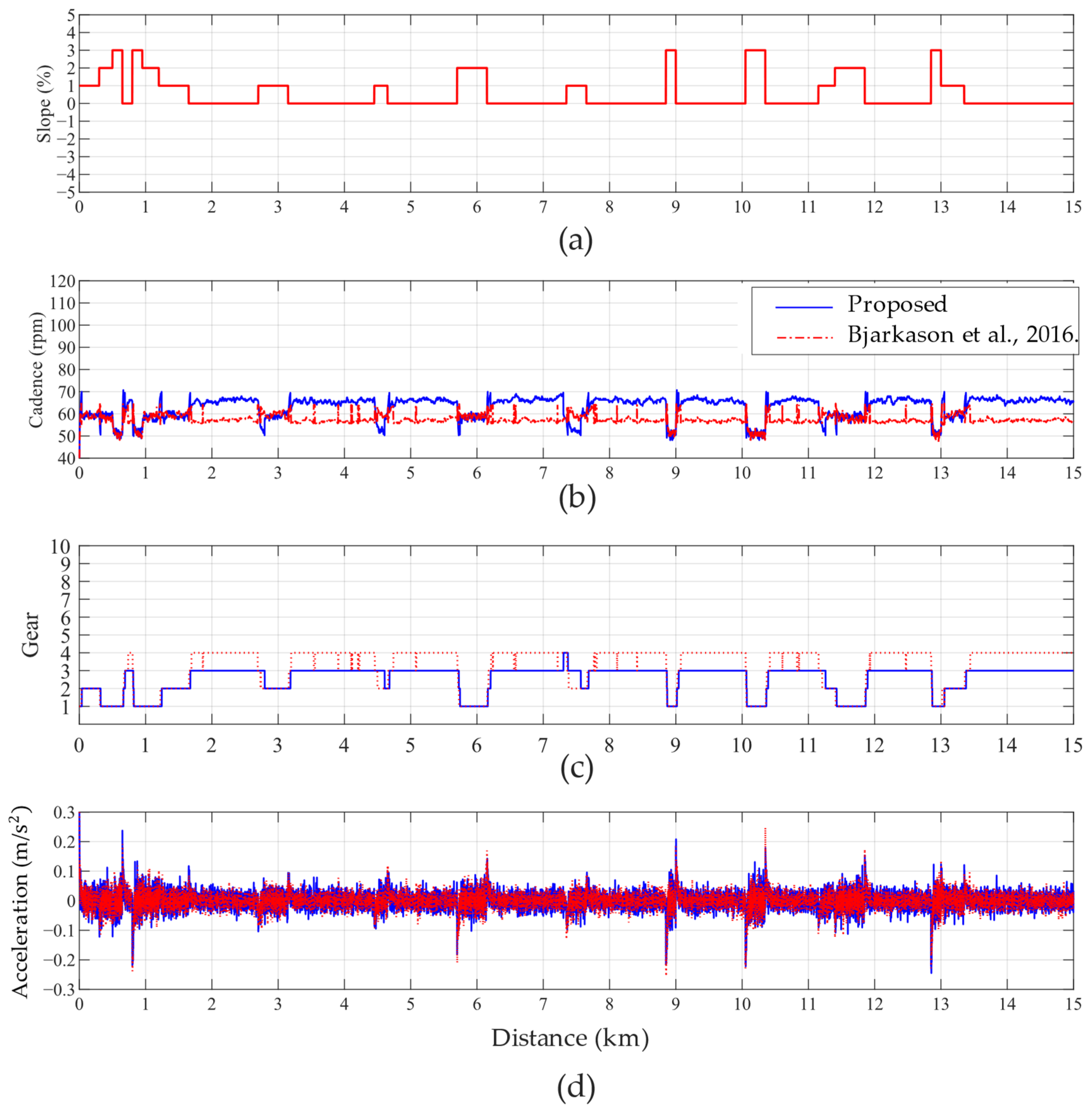
21] categorized exercise intensity into three levels with corresponding cadence targets of 60 rpm for commuting purposes, and 80–90 rpm for cardiovascular training. Using posture, they scored different cadences and gears, incorporating bicycle velocity as a fuzzy input to determine the output gear setting.
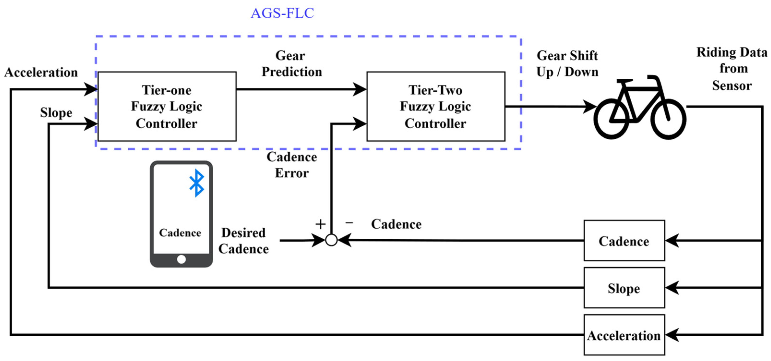
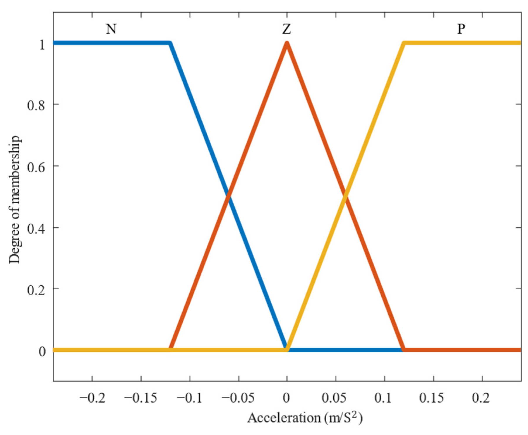
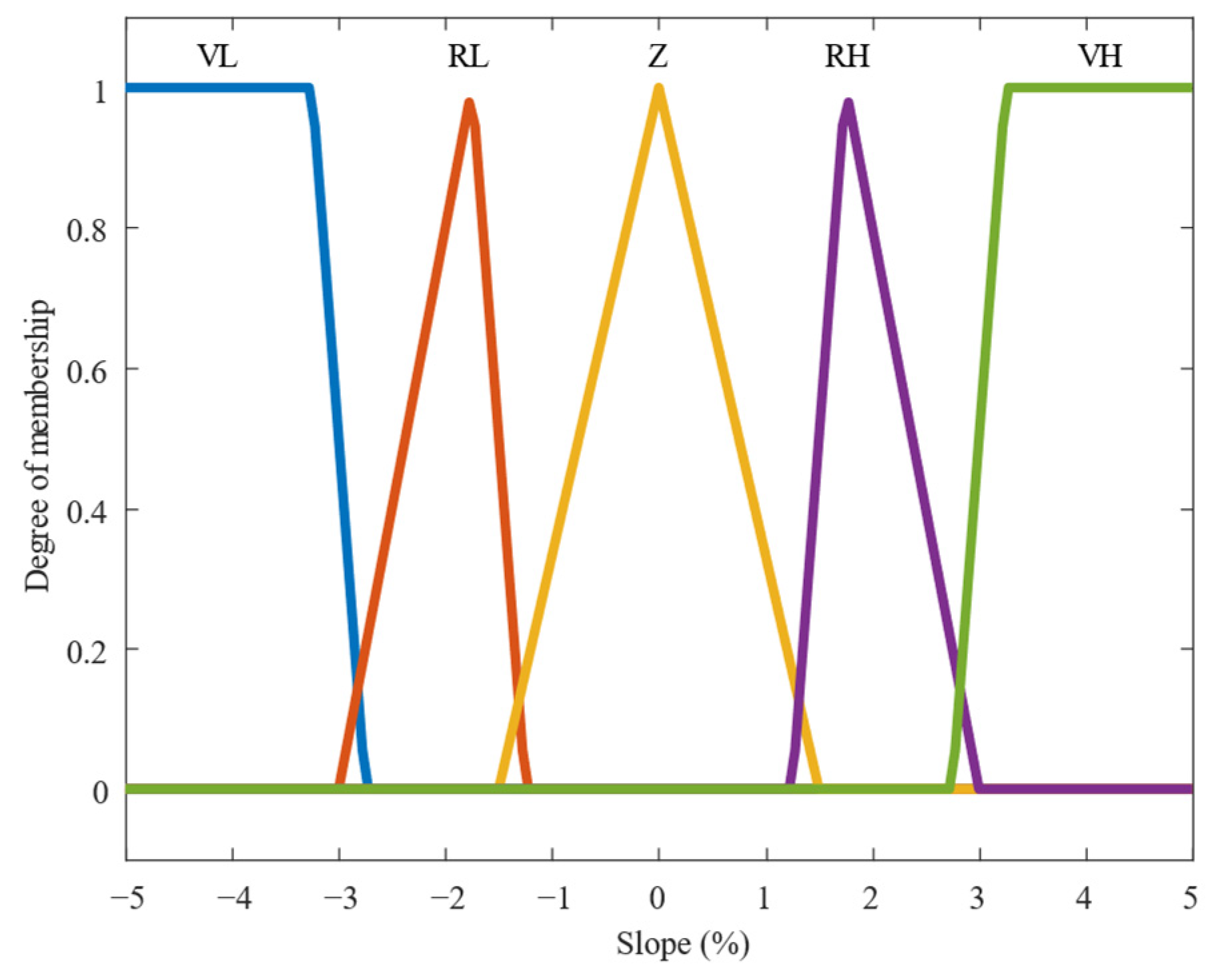
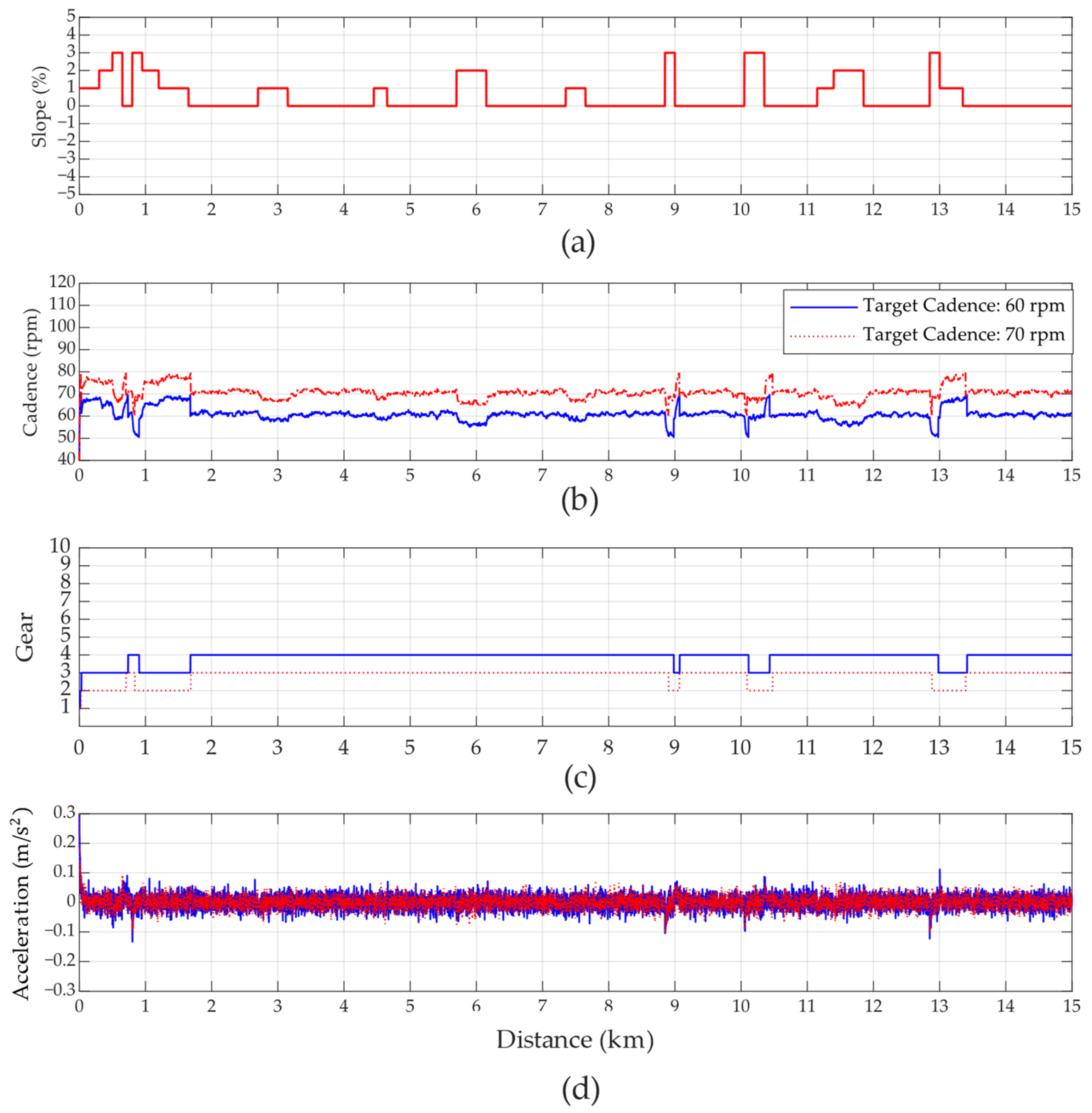
As mentioned earlier, several FLC-based approaches have been proposed for automatic gear shifting in electric bicycles. However, in many of these methods, cadence or bicycle velocity is commonly used as the input, which often leads to frequent shifting due to the positive correlation between bicycle velocity and cadence. In this paper, we propose a modified FLC, referred to as the automatic gear-shifting with FLC (AGS-FLC), for electric bicycles. The proposed scheme, inspired by insights from [5,10,
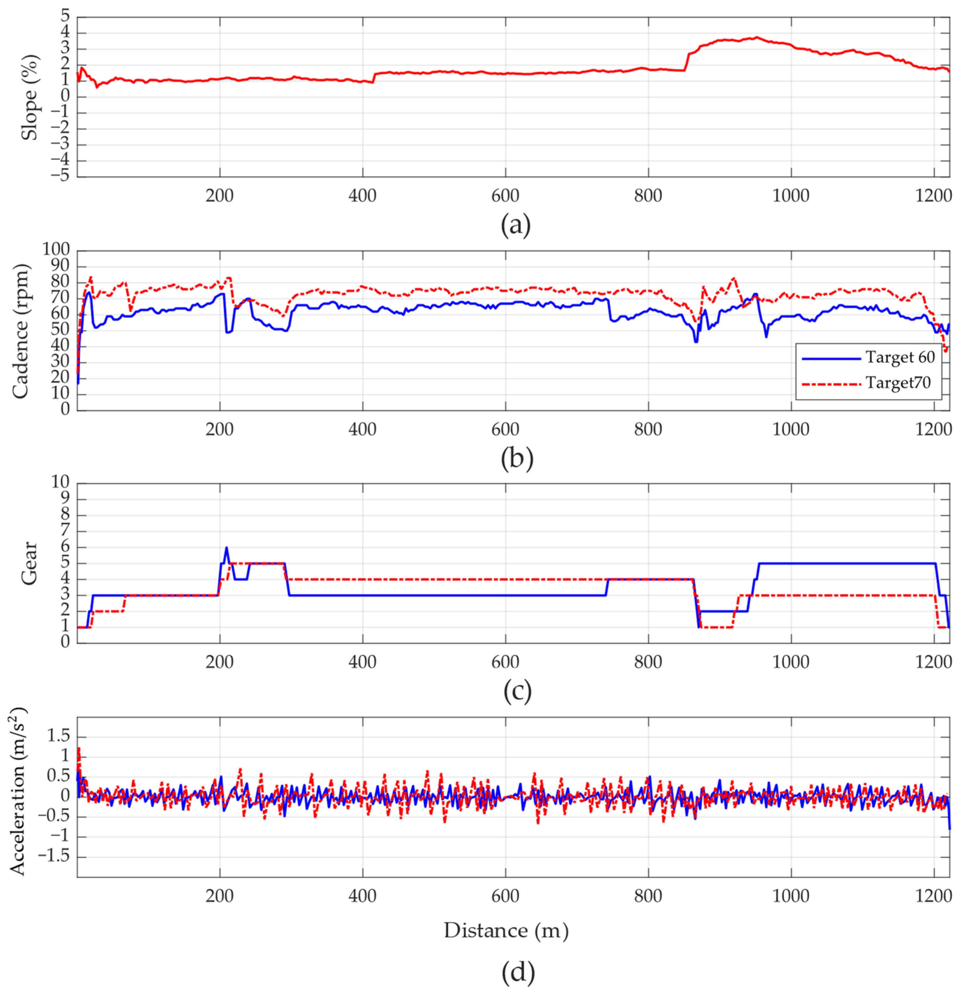
13], replaces bicycle velocity with acceleration changes in the membership functions to assess the impact of acceleration on riding comfort. Our primary contribution is the introduction of a novel AGS-FLC approach to reduce frequent shifting caused by acceleration and slope changes for electric bicycles in urban mobility solutions for smart cities. To the best of our knowledge, this approach has not been explored in this context before. Furthermore, we conducted both simulations and experimental evaluations to assess the effectiveness of the proposed AGS-FLC scheme across diverse rider profiles, including powerful, general, and powerless riders. The simulation and experimental results clearly demonstrate that our AGS-FLC scheme outperforms existing gear-shifting control methods in terms of performance, effectively addressing the issue of frequent shifting and validating our approach through experimental testing.
The structure of this paper is organized as follows: Section 2 provides a brief overview of bicycle dynamics modeling. Section 3 presents the proposed AGS-FLC scheme in detail. Section 4 showcases the simulation and experimental results. Finally, Section 5 offers the conclusion.

2. Modelling of Bicycle Dynamics

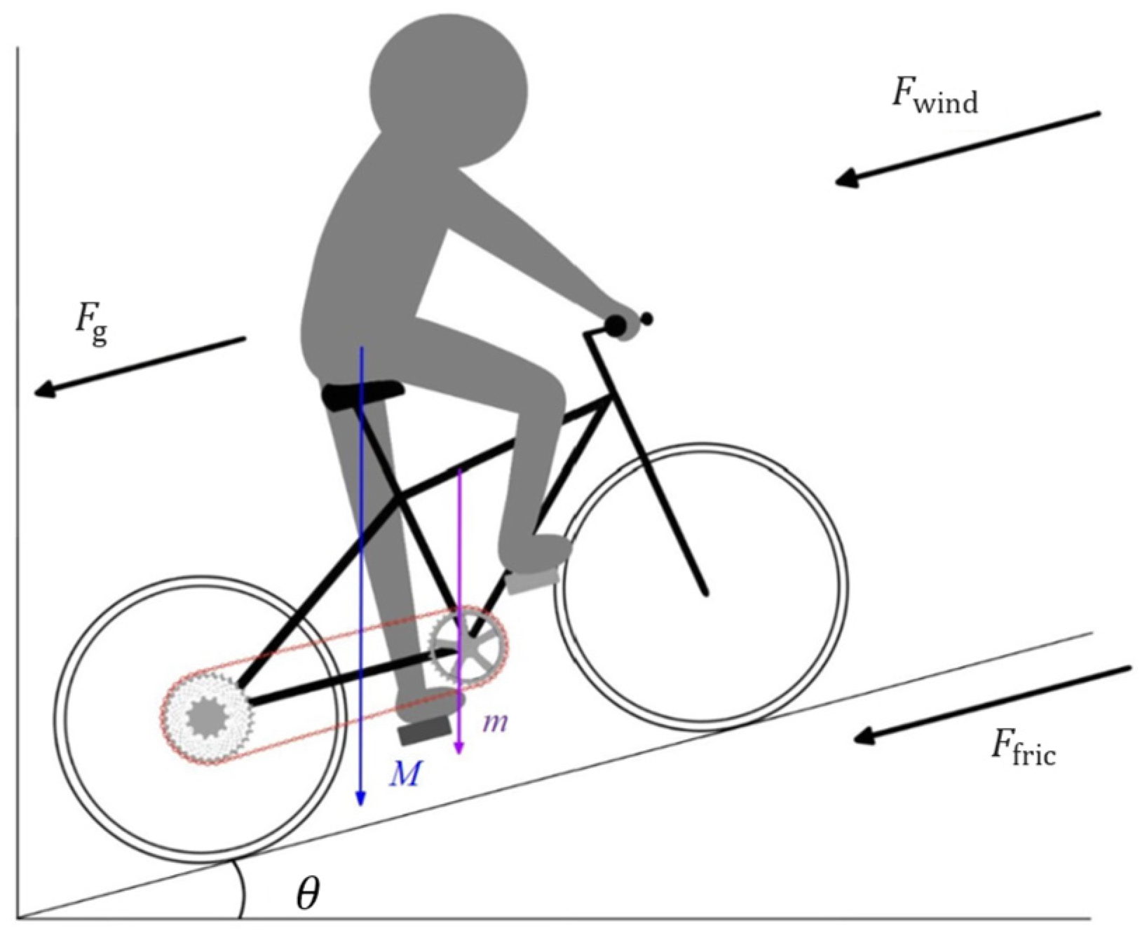
When the cyclist pedals to propel the bicycle forward, the dynamics can be illustrated as shown in Figure 1. The pedaling force applied to the pedals is transmitted to the rear wheel through the chainring and chain. This propelling force must exceed the resistive forces present in the environment, which include air resistance F wind , frictional resistance F fric , and the gravitational component on an incline F g , as described in Equations (1)–(3).
F wind = 0.5   ρ A c C d V bike 2
F fric = μ M g cos θ
F g = ( M + m ) g sin θ
Air resistance, or drag force, is influenced by the surrounding air medium and acts in the opposite direction of motion. It is determined by the drag coefficient C d , frontal area A c , air density ρ (kg/ m 3 ), and bicycle velocity V bike (km/h). Frictional resistance arises from the contact between the tires and the ground, producing a reactive force opposite to the direction of motion. It is influenced by the friction coefficient μ and the rider’s weight M (kg), the bicycle’s weight m (kg), and the angle θ (deg) between the road surface and the horizontal plane. Gravitational force on a slope F g is the component of the rider’s and bicycle’s weight due to Earth’s gravity and the slope angle. During uphill riding, F g increases as θ rises. The total environmental resistance forces, combined and multiplied by the velocity, yield the total dissipative power P dis , as shown in Equation (4).
P dis = ( F wind + F fric + F g ) V bike
The force applied by the rider on the pedals, P pedal , when multiplied by the gear ratio R , results in the propulsion power of the rear wheel, P ride , as expressed in Equation (5). The calculation of the gear ratio R is shown in Equation (6), T F is the number of teeth on the front chainring sprocket and T R is the number of teeth on the rear wheel cassette sprocket.
P ride = P pedal R
R = T F T R
The bicycle velocity V bike , combined with the gear ratio R and the wheel circumference C , yields the cadence C A D (rpm), as shown in Equation (7). To convert V bike from km/h, divide it by 3.6. Then, divide the product of the wheel circumference C and gear ratio R by this value, and multiply the result by 60 to obtain the cadence.
C A D = 60 × V bike C × R × 3.6
The propulsion force of the bicycle, as shown in Equation (8), is calculated by subtracting the power lost to environmental resistance from the forward power, and then dividing the result by the bicycle velocity. This propulsion force can be further divided by the total weight to determine the bicycle’s acceleration a (m/ s 2 ), as expressed in Equation (9).
F ride = ( P ride P dis ) / V bike
a = F ride / ( M + m )

3. Proposed Automatic Gear-Shifting with Fuzzy Logic Controllers

The architecture of the proposed automatic gear-shifting with a fuzzy logic controller (AGS-FLC) is shown in Figure 2. Initially, the rider inputs the target cadence. The system utilizes the slope and acceleration data to derive the prediction of gear-shifting through the first-stage FLC. Then, the error between the target and actual cadence is calculated. The second-stage FLC processes this error to determine whether a shift-up or shift-down is required. Finally, the controller area network (CAN) module sends commands to the electronic gear shifter, ensuring that the cadence is maintained within the target range.

3.1. Two-Stage Fuzzy Logic Controllers

The first-stage FLC takes acceleration and slope as input membership functions, and outputs the prediction of gear-shifting, also referred to as gear prediction. Among the most common scenarios for gear-shifting during cycling, aside from changes in bicycle velocity and cadence during startup, the most critical condition for shifting gears is slope variation. Therefore, in this study, the first-stage FLC uses slope as an input membership function. This design allows for real-time gear switching when riding on different terrains and ensures proper gear selection during startup on inclined surfaces. By incorporating acceleration, the system can capture the bicycle’s real-time dynamics, aiming to allocate the appropriate gear from the start. This approach prevents issues during slope starts, such as being unable to pedal effectively due to a high initial gear. The membership function for acceleration is shown in Figure 3, the linguistic values are “Negative, Zero, Positive”, and the abbreviations are expressed, respectively, as “N, Z, P”.
In the defuzzification phase, the inputs are transformed into membership functions. The membership function for slope is shown in Figure 4. The slope parameters are based on actual testing data from a riverside bicycle route, with slope values ranging between −5% and 5%. The linguistic values are “Very Low, Rather Low, Zero, Rather High, Very High”, and the abbreviations are expressed, respectively, as “VL, RL, Z, RH, VH”.
The output of the first-stage FLC is the gear prediction, which serves as the initial gear-shifting decision during startup and while riding through slope variations. Since bicycle gear systems are not designed for large-scale gear shifts, the gear-shifting values are confined to a range between −2 and +2. The linguistic values are “Shift-Down, Maintain Gear, Shift-Up”, as illustrated in Figure 5.
The first-stage fuzzy rule consists of two input variables, and the two variables are represented by three and five memberships. A total of 15 rules correspond to the output membership, as shown in Table 1, which describes the semantic relationships between acceleration and slope values. In this paper, acceleration is used instead of bicycle velocity, combined with slope as inputs, to determine whether the appropriate gear is selected during startup and whether the rider experiences a sudden deceleration due to insufficient pedaling power when encountering a slope. Based on the acceleration membership function, the gear is shifted to the appropriate position.
The second-stage FLC takes the gear prediction from the first-stage FLC and the cadence error as inputs for fuzzy computation. The cadence error is calculated as the difference between the rider’s ideal cadence and the actual cadence. The linguistic values are “Positive Low, Rather Low, Zero, Rather High, Positive High”, and the abbreviations are expressed, respectively, as “PL, RL, Z, RH, PH”, as shown in Figure 6.
The second-stage output is the gear-shifting command, which is transmitted through CAN instructions. These commands are sent to the electronic transmission system via the CAN module. The transmission system executes gear-shifting based on the received commands, with gear shift values designed to range between −2 and +2. The linguistic values are “Shift-Down, Maintain Gear, Shift-Up”, as shown in Figure 7.
The second-stage fuzzy rule consists of two input variables, and the two variables are represented by three and five memberships. A total of 15 rules correspond to the output membership, as shown in Table 2, which shows the gear prediction and cadence error as semantic inputs and outputs the semantic descriptions of gear-shifting actions. The cadence error is defined as the ideal cadence input by the rider minus the current cadence.
The operation process of AGS-FLC is detailed in Algorithm 1. The program begins (Lines 1–5) by initializing variables, including setting the simulated route slope and the FLC rule base. Once the rider inputs the ideal cadence, the program enters a while loop (Line 6). Within the loop, parameters such as bike velocity, acceleration, and cadence are calculated based on the rider’s pedaling force (Line 7). These parameters, together with the pre-defined slope (Line 8), serve as inputs to the first-stage FLC, which outputs the gear prediction (Line 9). The cadence error and the gear prediction derived (Line 10) are then fed into the second-stage FLC, which outputs the gear change command (Line 11).
Algorithm 1. Automatic Gear Shifting with Fuzzy Logic Controller
Input:        Gear: The gear position of the bicycle.
     P pedal : pedal power
     C a d e n c e err : The error between the current cadence and the desired cadence.
    Velocity: velocity of bike
    Slope: Simulation of slope testing in reality
Output:         G e a r change : Gear change command
Function:      FuzzyOne func(Slope, acceleration, rule base1);
                 //return G e a r prediction ;
         FuzzyTwo func( G e a r prediction , Cadence, rule base2);
               //return Gear change command;
Initialization:

1.  Initial setting of parameters.
2.  { G e a r prediction , Velocity, C a d e n c e err } = 0;
3.  Set the slope for the simulated route.
4.  Fuzzy Rule setting.
5.   R B ← default; //rule base for the ordinary rider (0–100 W)
Main:
6.    while (Cadence){
7.      Load the P pedal input and calculate acceleration, slope for FLC.
8.      Acceleration, slope for Fuzzy tier1.
9.       G e a r prediction = FuzzyOne func(Slope, acceleration, rule base1);
10.      G e a r prediction , C a d e n c e err for Fuzzy tier2.
11.      G e a r change command = FuzzyTwo func( G e a r prediction , C a d e n c e err , rule base2);
12.     }

3.2. Compared with Previous Work

In the study of automatic gear-shifting, many references use bicycle velocity to estimate cadence. As the bicycle velocity increases within the same gear, cadence naturally rises as well. When the cadence exceeds the optimal range for the current gear, it indicates the need to shift up to maintain cadence within the target range. As shown in the approaches of [20,21]. This approach is well-suited for controlling a limited number of sensors, such as through condition-based or threshold-based control. However, when multiple sensors are integrated, the likelihood of issues such as frequent shifting increases. For example, in [16], which combines multiple learning models, frequent shifting is observed in the results. Many studies employing fuzzy logic, such as [20] employ a threshold to reduce the frequency of shifting. In [20], frequent shifting also arises when bicycle velocity falls within overlapping membership regions of two gears, causing the output to oscillate between the two gear positions. Following the method of [21], this study calculates the bicycle velocity corresponding to different gear cadences at 60 ± 10 rpm and uses this velocity as the membership function for gear control. However, this approach still encounters frequent shifting, as indicated by the arrows in Figure 8c, especially during slope changes; as shown in Figure 8a, when frequent shifting occurs, cadence also experiences significant fluctuations, as illustrated in Figure 8b. After reviewing several studies that incorporate acceleration as a control parameter, this study decides to replace bicycle velocity with acceleration as an input to the fuzzy controller, effectively mitigating frequent shifting. The simulation results demonstrate improvements in shifting stability when acceleration is added to the original framework.
Slope is another critical factor when bringing cycling scenarios into real-world applications. In [5], the authors integrate a slope sensor and set the slope input based on measured variations in the test route. The simulation results clearly show that AGS-FLC not only stabilizes cadence around the target but also enhances the stability of gear-shifting under varying slope conditions.

4. Simulations and Experiments

In the previous sections, the rationale for using fuzzy logic as the controller for automatic gear-shifting was explained, along with the challenges encountered when implementing fuzzy logic. This section validates the proposed method through simulation, referencing [4], which used bicycle dynamic stability as an indicator. The acceleration variation is considered a key factor. The simulation divides cadence into three scenarios for comparison: sufficient pedaling force with pedaling power ranging from 0 to 140 W, defined as powerful, moderate pedaling force with pedaling power ranging from 0 to 100 W, defined as general, and insufficient pedaling force with pedaling power ranging from 0 to 60 W, defined as powerless. The parameters used in the bicycle dynamic simulation are listed in Table 3.

4.1. Evaluation Indices

  • Safety
This study refers to [4], which defines the safe acceleration range as −0.4 m/s2 to 0.4 m/s2. The safety level is expressed by Equation (10), and the safety metric is defined as shown in Equation (11).
S a f e   Z o n e = { 0.4   m / s 2 ,   0.4   m / s 2 }
S a f e t y = N u m b e r s   o f   v e l o c i t y   w i t h i n   S Z T o t a l   p e d a l i n g   n u m b e r s × 100 %
  • Mean of Cadence
The mean is a fundamental concept in statistics used to measure the central tendency or the center position of a dataset. By dividing the sum of all cadence values by the total number of pedal strokes ( n ), it is possible to evaluate whether the distribution of cadence aligns with the target cadence. The formula for calculating the mean value is shown in Equation (12).
Mean   ( C a d e n c e 1 : n ) = 1 n i = 1 n C a d e n c e i
  • Acceleration Ripple
Following the method in [7], the acceleration ripple is obtained by subtracting the lowest extreme value from the highest extreme value during the cycling process. In this study, the acceleration values throughout the entire process are stored in an array, referred to as Acc [all]. The maximum and minimum values are then calculated from this array, and their difference is defined as the A c c ripple , as shown in Equation (13). This approach helps evaluate the bicycle’s velocity stability when encountering varying road conditions or changes in slope. In cases of frequent shifting, the frequent changes in the gear may lead to fluctuations in acceleration, causing discomfort during riding.
A c c r i p p l e = Max   ( A c c   [ all ] ) Min   ( A c c   [ all ] )

4.2. Simulations for Powerful Riders

The simulation results for powerful riders are presented in Figure 9. Under the target cadence of 60 rpm, powerful riders with sufficient pedaling power experience only a slight drop in cadence, even when climbing a 3° slope, as shown in Figure 9a,b at the 9 km, 10 km, and 13 km points of the slope. In comparison with the cadence shown in plot Figure 9b, the cadence remains consistently within the target range of 60 ± 10 rpm throughout the entire simulation. In Figure 9c, it can be observed that the method proposed in [21] tends to induce frequent shifting, which disrupts cadence stability in Figure 9b. The change in acceleration, as shown in Figure 9d, is approximately the same.

4.3. Simulations for General Riders

The simulation results for General Riders are presented in Figure 10. During a 3° slope climb, the pedaling force remains adequate to overcome the incline. Although the cadence decreases sharply upon encountering the slope, as shown in the slope diagram in Figure 10a, it rarely falls below the target range of −10 rpm at the 9 km, 10 km, and 13 km points. In comparison with plot Figure 10b, it can be observed that as the cadence approaches 50 rpm, the controller promptly shifts down to stabilize it. Once the cadence recovers, the controller adjusts back to an appropriate gear to maintain stability. Frequent shifting can still be observed in Figure 10c for the method proposed in [21], while the acceleration change in Figure 10d is approximately the same.

4.4. Simulations for Powerless Riders

The simulation results for powerless riders are shown in Figure 11. Figure 11a shows that the 3° slope occurs at the 9 km, 10 km, and 13 km points. Due to insufficient pedaling power, the riders are unable to maintain the target cadence of 60 rpm, as depicted in Figure 11b. Even with the gear shifted down to the lowest level, as shown in Figure 11c, the cadence slightly exceeds the target range. This illustrates that riders with limited pedaling strength may opt for a lower cadence or resort to walking their bicycles to traverse the slope. Compared to [21], the proposed method demonstrates a lower average gear level and less frequent shifting, resulting in slightly more stable acceleration values in Figure 11d.
Simulation parameters for different power zone riders at a target cadence of 60 rpm are summarized in Table 4. The results indicate that both methods effectively maintain the cadence near the target value. However, in the simulations for powerless riders, the method proposed in [21] results in more frequent shifting, leading to a lower cadence and slightly higher acceleration ripple.

4.5. Simulations for Powerful Riders at Target Cadences of 60 and 70 rpm

The proposed method allows users to adjust the pedaling error attribution function. This section presents a comparison with the target cadence set to 70 rpm, distinguishing pedaling power across powerful, general power, and powerless riders. The simulations for powerful riders are shown in Figure 12. When the target is adjusted to 70 rpm, it can be observed that Figure 12a–c represent the slope, cadence, and gear, respectively. Under the same pedaling power, the controller keeps the gear in a lower range to achieve a higher target cadence. Due to sufficient pedaling power, the cadence remains relatively stable even when encountering slopes. Compared to the target of 60 rpm, the controller successfully maintains the cadence within a higher range. Additionally, as shown in Figure 12d, the acceleration ripple values for both targets are almost identical and successfully achieve the desired cadence goals.

4.6. Simulations for General Riders at Target Cadences of 60 and 70 rpm

The simulations for General Riders are shown in Figure 13. The pedaling power of General Riders is sufficient to handle a 3° slope. However, as seen in Figure 13a–c at the steeper slope points located at 1 km, 9 km, 10 km, and 13 km, the cadence exhibits more significant fluctuations. In addition, as shown in Figure 13d, the acceleration at these points exceeds the predefined membership function, prompting the gear to downshift in a timely manner to maintain the target cadence. Overall, the gear positions for General Riders are lower than those for powerful riders, which helps sustain a higher cadence.

4.7. Simulations for Powerless Riders at Target Cadences of 60 and 70 rpm

When the target cadence for powerless riders is set to 70 rpm, due to insufficient pedaling force, as seen in Figure 14a at the 1 km, 9 km, and 13 km points of the slope, even though the gear shifts down in a timely manner, as shown in Figure 14c, the cadence in Figure 14b still drops sharply, with acceleration exhibiting significant fluctuations, as shown in Figure 14d. Although the controller operates correctly, the lack of sufficient pedaling force causes the cadence to stabilize at around 50 rpm after shifting to the lowest gear. As a result, the overall cadence exhibits greater fluctuations.
The simulation results are summarized in Table 5, where it is evident that for powerful riders, the average cadence under the 70 rpm target is slightly lower than expected. This is a natural occurrence, as powerful riders are able to maintain cadence within the target range even under slope variations, prompting the controller to avoid frequent shifting, resulting in a slightly lower average cadence than 70 rpm.

4.8. Experiment Results

The bicycle used in this study is shown in Figure 15. The hardware development platform is based on the Arduino MEGA 2560, selected for its superior hardware resources compared to the widely used Arduino Uno. The MEGA 2560 provides more I/O pins, expanded memory capacity, and six external interrupts, along with support for multiple communication protocols, including universal asynchronous receiver/transmitter (UART), serial peripheral interface (SPI), and inter-integrated circuit (I2C). These features make it an ideal choice to meet the hardware demands of this study. The platform facilitates communication with various sensors, such as those for Bluetooth, velocity, cadence, inertial measurement unit (IMU), and gear-shifting detection. The Bluetooth module employed is the HC-06, enabling users to set the target cadence via a mobile app. Wheel rotation speed is monitored using a Hall sensor. A magnet affixed to the wheel triggers the Hall sensor as it passes by, causing an external magnetic field to generate an interrupt signal on the Arduino MEGA 2560, which calculates the current velocity and acceleration. Cadence is measured with a torque and speed sensor that utilizes piezoelectric technology to capture the rider’s torque, cadence, and pedaling power. Slope detection is accomplished using the MPU6050 IMU sensor, which measures changes in the Y-axis angle and converts them into slope values. The MCP2515 CAN expansion module connects to the main controller via the SPI interface to facilitate electronic gear-shifting by exchanging data with the electronic gear shifter. The electronic gear shifter used in this study is the Cypher10, which supports 10-speed gear-shifting and employs the CAN Bus communication protocol. Gear-shifting is executed by transmitting and receiving specific CAN IDs to select the desired gear.
The selected route for the experiments is the riverside park cycling path in Taipei City, Taiwan, with a total riding distance of 1.2 km, as shown in Figure 16. Taipei City, located within a basin terrain, is intersected by several rivers, resulting in slight slope variations across different sections of the path. These cycling paths, which connect New Taipei City and Taipei City, feature wide lanes that serve multiple purposes: recreational areas for residents, training routes for cycling enthusiasts, and essential commuting corridors for individuals traveling to and from work.
The experimental results are illustrated in Figure 17. During the tests, gear shifts were observed to correspond to slope changes, as shown in Figure 17a,c. However, it was noted that the method described in [21] led to frequent shifting, which significantly impacted cadence, as seen in Figure 17b, causing notable fluctuations in cadence and acceleration (Figure 17d). Moreover, under real-world conditions, gear shifting involves repositioning the derailleur and waiting for the chain to fully engage with the target sprocket before completing the shift. If another gear shift is initiated during this process, it can result in substantial rider discomfort.
Table 6 compares the parameters of the proposed method with [21]. The quantitative results indicate that AGS-FLC achieves reduced acceleration ripples and improved safety.

4.9. Experiments Comparing Target Cadences of 60 and 70 rpm

The experimental results with a target cadence set at 70 rpm are shown in Figure 18. From the 800 m to 1000 m section in Figure 18a–c, it can be observed that regardless of the target cadence, the controller quickly shifts down the gear to maintain cadence due to the steep increase in slope. However, during the tests, factors such as road vibrations, wind resistance, and ongoing gear shifts caused minor variations in pedaling power, which impacted bicycle velocity and resulted in unstable acceleration parameters, as shown in Figure 18d. The instability in acceleration prevented it from being precisely controlled according to the designed membership functions. This limitation is a drawback of the current testing and serves as one of the key areas for future improvement. Fortunately, the second-stage cadence error input functions as a confirmation mechanism. By using the cadence error, the gear shifter can perform as expected, controlling gear shifts effectively.
Table 7 presents the experimental results for the proposed method at cadence targets of 60 and 70 rpm. It can be observed that the average cadence for the target of 70 rpm falls within the desired range, this demonstrates that the proposed method can adapt the target cadence based on the rider’s needs, such as fatigue or discomfort. However, due to the higher pedaling force, the increased acceleration leads to reduced safety and higher acceleration ripples.

5. Conclusions

In the context of smart cities, bicycle-sharing systems have emerged as vital last-mile transportation solutions, seamlessly integrating into urban mobility networks. This paper reviewed recent advancements in automatic gear-shifting systems and electrically assisted bicycle control methods, emphasizing their objectives and evaluation metrics. Among these methods, fuzzy logic controls were chosen for their simplicity, adaptability, and ease of implementation. However, frequent shifting remains a significant challenge in FLC-based approaches, adversely affecting rider comfort and system performance. To address this issue, the proposed AGS-FLC incorporates slope and acceleration as key input parameters, derived from an in-depth analysis of bicycle dynamics and refined membership function design. By integrating slope data into the control scheme, the proposed system better reflects real-world cycling conditions. Additionally, cadence was included as an input variable, allowing customization for individual rider preferences and enhancing the overall adaptability of the system. The effectiveness of the AGS-FLC was validated through both simulations and experimental evaluations across a diverse range of rider profiles, including powerful, general, and powerless riders. The results demonstrated that the proposed approach significantly reduces acceleration ripple, maintains average cadence within the target range, and aligns gear shifts with the intended design. Notably, this leads to a substantial 20% improvement in safety and a reduction of 1 m/s2 in acceleration ripple. Moreover, the AGS-FLC effectively eliminates the problem of frequent shifting, thereby improving riding comfort and efficiency. These advancements hold great promise for public bicycle-sharing systems, offering a robust, adaptable, and rider-centric solution suitable for various cycling conditions and rider capabilities. The integration of AGS-FLC into smart city transportation frameworks could further enhance urban mobility, contributing to sustainable and efficient mobility solutions for diverse user needs. Future research directions will focus on enhancing the stability of sensors and conduct tests with users of different age groups and physical abilities, thereby enriching our experimental data. As mentioned earlier, the instability in acceleration has hindered precise control in accordance with the designed membership functions. This limitation represents a significant drawback in the current testing process and serves as one of the key areas for future improvement.

Author Contributions

Conceptualization, J.-S.L. and R.Y.; methodology, J.-S.L. and R.Y.; software, R.Y.; validation, R.Y.; formal analysis, R.Y.; investigation, J.-S.L. and R.Y.; resources J.-S.L.; data curation, R.Y.; writing—original draft preparation, J.-S.L. and R.Y.; writing—review and editing, J.-S.L. and R.Y.; visualization, R.Y.; supervision, J.-S.L.; project administration, J.-S.L.; funding acquisition, J.-S.L. All authors have read and agreed to the published version of the manuscript.

Funding

This work was supported by the Cycling & Health Tech Industry R&D Center and National Science and Technology Council (113-2221-E-027-070), Taiwan.

Data Availability Statement

The data presented in this study are available on request from the corresponding authors due to privacy restrictions.

Conflicts of Interest

Author Ruo You is employed by Phoenix Technologies Ltd. The remaining authors declare that the research was conducted in the absence of any commercial or financial relationships that could be construed as a potential conflict of interest.

References

  1. Browning, D.L. Method and System for Computer-Controlled Bi-Cycle Gear-Shifting. U.S. Patent 5261858, November 1993. [Google Scholar]
  2. Abagnale, C.; Cardone, M.; Iodice, P.; Marialto, R.; Strano, S.; Terzo, M.; Vorraro, G. Design and development of an innovative e-bike. Energy Procedia 2016, 101, 774–781. [Google Scholar] [CrossRef]
  3. Lee, J.S.; Jiang, J.W. Enhanced fuzzy-logic-based power-assisted control with user-adaptive systems for hu-man-electric bikes. IET Intell. Transp. Syst. 2019, 13, 1492–1498. [Google Scholar] [CrossRef]
  4. Lee, J.S.; Chen, Z.-H.; Hong, Y. Enhancing urban mobility with self-tuning fuzzy logic controllers for power-assisted bicycles in smart cities. Sensors 2024, 24, 1552. [Google Scholar] [CrossRef] [PubMed]
  5. Dai, J.H.; Lee, J.S. Development of fuzzy-logic-based controllers for energy conservation in human-electric bikes. In Proceedings of the 2021 IEEE International Conference on Consumer Electronics-Taiwan (ICCE-TW), Penghu, Taiwan, 18 September 2021. [Google Scholar]
  6. Uyar, O.; Çunkaş, M.; Karaca, H. Enhanced intelligent control with adaptive system for electrically assisted bicycle. Eng. Sci. Technol. Int. J. 2022, 30, 101047. [Google Scholar]
  7. Ho, P.-J.; Yi, C.-P.; Lin, Y.-J.; Chung, W.-D.; Chou, P.-H.; Yang, S.-C. Torque measurement and control for electric-assisted bike considering different external load condition. Sensors 2023, 23, 4657. [Google Scholar] [CrossRef]
  8. Giani, P.; Tanelli, M.; Savaresi, S.M. Identification and control of a continuously variable transmission for bicycles. In Proceedings of the IET Conference on Control and Automation 2013: Uniting Problems and Solutions, Birmingham, UK, 4–5 June 2013; pp. 1–6. [Google Scholar]
  9. Rockwood, D.; Parks, N.; Garmire, D. A continuously variable transmission for efficient urban transportation. Sustain. Mater. Technol. 2014, 1, 36–41. [Google Scholar] [CrossRef]
  10. Chen, C.-L.; Tsai, M.-C. Torque control of power-assisted bike via planetary gear mechanism. In Proceedings of the 2017 20th International Conference on Electrical Machines and Systems (ICEMS), Sydney, NSW, Australia, 11–14 August 2017; pp. 1–5. [Google Scholar]
  11. Tandon, P.; Awasthi, A.; Mishra, B.K.; Rathore, P.; Shukla, R.K. Design and simulation of an intelligent bicycle transmission system. IEEE/ASME Trans. Mechatron. 2011, 16, 509–517. [Google Scholar]
  12. Rauch, Y.; Hinger, S. Modelling the Propulsion Behaviour of an E-Bike-Rider. ResearchGate, Reports on Energy Efficient Mobility; Zenodo: Geneva, Switzerland, 2021; Chapter 5; pp. 29–34. [Google Scholar]
  13. Savaresi, D.; Dettù, F.; Formentin, S.; Savaresi, S.M. On optimal gear-shifting in city bicycles. IFAC J. Syst. Control 2022, 22, 100211. [Google Scholar]
  14. Atencio, L.G.M.; Cena, J.S.E.; Opalla, I.U.; Angelia, R.E. Arduino-based electronic bicycle transmission switching system. In Proceedings of the International Conference on Mechanical Engineering Research, Krakow, Poland, 11–13 December 2021; Springer Nature: Singapore, 2021. [Google Scholar]
  15. Ay, F.C.; Kılınç, B.; Ercan, T.E.; Kağızman, A.; Sezer, V. Design, implementation, and control of a novel Automated Manual Transmission (AMT) system for manual transmission bicycles. In Proceedings of the 2024 Innovations in Intelligent Systems and Applications Conference (ASYU), Ankara, Turkiye, 16–18 October 2024; pp. 1–6. [Google Scholar]
  16. Lin, H.-Y.; Wu, Z.-Y. Development of automatic gear-shifting for bicycle riding based on physiological information and environment sensing. IEEE Sens. J. 2021, 21, 24591–24600. [Google Scholar] [CrossRef]
  17. Ho, C.-H.; Lin, H.-Y. Bicycle gear-shifting prediction using environmental information and physiological data. In Proceedings of the 2023 IEEE International Conference on Consumer Electronics (ICCE), Las Vegas, NV, USA, 6–8 January 2023; pp. 1–6. [Google Scholar]
  18. Lin, T.Y. Apply fuzzy logic to smart-bike controller design. In Proceedings of the Fourth International Symposium on Uncertainty Modeling and Analysis, ISUMA 2003, College Park, MD, USA, 21–24 September 2003; pp. 208–212. [Google Scholar]
  19. Tsai, C.-C.; Kao, J.-C.; Chang, C.-F. Interval type-2 fuzzy gear-changing control for intelligent bikes. In Proceedings of the 2014 International Conference on Machine Learning and Cybernetics, Lanzhou, China, 13–16 July 2014; pp. 741–747. [Google Scholar]
  20. Lin, S.K.; Yang, S.W.; Cheng, C.C. Design of an automatic shift control system with self-learning ability for a bicycle. J. Chin. Inst. Eng. 2015, 38, 594–602. [Google Scholar]
  21. Bjarkason, V. Optimal Bicycle Gear Selection Using Multi-Sensor Data Fusion. Master’s Thesis, University College of Southeast Norway, Department of Electrical Engineering, IT and Cybernetics, Porsgrunn, Norway, 2016. [Google Scholar]
Figure 1. Bicycle riding dynamics.
Systems 13 00228 g001
Figure 2. System architecture diagram of AGS-FLC.
Systems 13 00228 g002
Figure 3. Membership functions of acceleration.
Systems 13 00228 g003
Figure 4. Membership functions of slope.
Systems 13 00228 g004
Figure 5. Membership functions of gear prediction.
Systems 13 00228 g005
Figure 6. Membership functions of cadence error.
Systems 13 00228 g006
Figure 7. Membership functions of gear change.
Systems 13 00228 g007
Figure 8. Comparison of the original framework with the addition of acceleration as an input. (a) Slope, (b) cadence [21], and (c) gear shifting.
Systems 13 00228 g008
Figure 9. The simulation targets a cadence of 60 rpm for riders with powerful pedaling forces, considering variations in (a) slope, (b) cadence [21], (c) gear-shifting, and (d) acceleration variation.
Systems 13 00228 g009
Figure 10. The simulation targets a cadence of 60 rpm for riders with general power pedaling forces, considering variations in (a) slope, (b) cadence [21], (c) gear-shifting, and (d) acceleration variation.
Systems 13 00228 g010
Figure 11. The simulation targets a cadence of 60 rpm for riders with powerless pedaling forces, considering variations in (a) slope, (b) cadence [21], (c) gear-shifting, and (d) acceleration variation.
Systems 13 00228 g011
Figure 12. Comparison of powerful riders at cadence targets of 60 and 70 rpm, considering variations in (a) slope, (b) cadence, (c) gear-shifting, and (d) acceleration variation.
Systems 13 00228 g012
Figure 13. Comparison of General Riders at cadence targets of 60 and 70 rpm, considering variations in (a) slope, (b) cadence, (c) gear-shifting, and (d) acceleration variation.
Systems 13 00228 g013
Figure 14. Comparison of Powerless Riders at cadence targets of 60 and 70 rpm, considering variations in (a) slope, (b) cadence, (c) gear-shifting, and (d) acceleration variation.
Systems 13 00228 g014
Figure 15. The developed AGS-FLC bike.
Systems 13 00228 g015
Figure 16. The main routes for the experiments.
Systems 13 00228 g016
Figure 17. Experiments for the proposed method and [21], considering variations in (a) slope, (b) cadence, (c) gear-shifting, and (d) acceleration variation.
Systems 13 00228 g017
Figure 18. Comparison between cadence targets of 60 and 70 rpm with the proposed method, considering variations in (a) slope, (b) cadence, (c) gear-shifting, and (d) acceleration variation.
Systems 13 00228 g018
Table 1. The first-stage fuzzy rules of AGS-FLC.
AccelerationNZP
Slope
VLMaintain GearMaintain GearShift-Up
RLMaintain GearMaintain GearShift-Up
ZShift-DownMaintain GearShift-Up
RHShift-DownMaintain GearMaintain Gear
VHShift-DownMaintain GearMaintain Gear
Table 2. The second-stage fuzzy rules of AGS-FLC.
Gear PredictionShift-DownMaintain GearShift-Up
Cadence Error
VLShift-DownShift-DownShift-Down
RLShift-DownShift-DownMaintain Gear
ZMaintain GearMaintain GearMaintain Gear
RHMaintain GearShift-UpShift-Up
VHShift-UpShift-UpShift-Up
Table 3. Simulation parameters.
Parameter of Bicycle Dynamics
M, mMass of Bicycle and Cyclist10 kg/80 kg
T F , T R The teeth of
Front chainring/Rear Cassette
Front: 40
Rear: 11-13-15-17-19-21-24-28-32-38
R wheel Radius of wheel0.33 m
P pedal Pedal powerPowerful: 0–140 W
General: 0–100 W
Powerless: 0–60 W
gGravity acceleration9.81
ρ Density of air1.18 kg/ m 3
C d Aerodynamic drag coefficient0.5
A c Front area1 m 2
μ Coefficient of friction0.014
Table 4. Simulation parameters for different power zone riders at target 60 rpm.
IndexSafety (%)Mean Cadence (rpm)Acceleration Ripple (m/ s 2 )Distance (km)
Rider/Method
Powerful riderBjarkson et al. [21]99.9760.320.2215
AGS-FLC 99.9760.070.2215
GeneralriderBjarkson et al. [21]99.9860.650.2915
AGS-FLC99.9860.880.2415
Powerless riderBjarkson et al. [21]99.9954.720.6115
AGS-FLC99.9962.330.4515
Table 5. Simulation parameters for different power zone riders at cadence targets of 60 and 70 rpm.
IndexSafety (%)Mean Cadence (rpm)Acceleration Ripple (m/ s 2 )Distance (km)
Rider/Target Cadence
Powerful rider60 rpm99.9760.070.2215
70 rpm99.9768.060.2415
General rider60 rpm99.9860.880.2415
70 rpm99.9870.580.2615
Powerless rider60 rpm99.9962.330.4515
70 rpm99.9970.190.4415
Table 6. Comparison of experimental results between the proposed method and [21].
IndexSafety (%)Mean Cadence (rpm)Acceleration Ripple (m/ s 2 )Distance (m)
Method
Bjarkson et al. [21]75.5362.592.611221
AGS-FLC 97.2261.581.601203
Table 7. Experimental results for the proposed method at cadence targets of 60 and 70 rpm.
Index Safety (%)Mean Cadence (rpm)Acceleration Ripple (m/ s 2 )Distance (m)
Cadence
(rpm)
6097.2261.581.601203
70 85.5871.851.951218
Disclaimer/Publisher’s Note: The statements, opinions and data contained in all publications are solely those of the individual author(s) and contributor(s) and not of MDPI and/or the editor(s). MDPI and/or the editor(s) disclaim responsibility for any injury to people or property resulting from any ideas, methods, instructions or products referred to in the content.

