Article

Formalizing Attack Tree on Security Object for MySANi in Legal Metrology

1
Electrical Group, National Metrology Institute of Malaysia, Sepang 43900, Malaysia
2
Center for Cyber Security, Faculty of Information Science and Technology, Universiti Kebangsaan Malaysia, Bangi 43600, Malaysia
3
Department of Electrical, Electronic and Systems Engineering, Faculty of Engineering and Built Environment, Universiti Kebangsaan Malaysia, Bangi 43600, Malaysia
4
Department of Informatics, Faculty of Science and Technology, UIN Sunan Kalijaga, Yogyakarta 55281, Indonesia
*
Author to whom correspondence should be addressed.
Systems 2023, 11(1), 49; https://doi.org/10.3390/systems11010049
Submission received: 16 December 2022 / Revised: 10 January 2023 / Accepted: 11 January 2023 / Published: 16 January 2023

Abstract

:
Illegal software manipulation is one of the biggest issues in software security. This includes the legally relevant software which are now crucial modules in weight and measuring instruments such as weighbridges. Despite the advancement and complexity of weight and measuring instruments, the inspection methodology is weak and lacks of innovation. The conventional inspection method is merely based on the observation printed certificate of the software. This paper introduces Malaysia Software-Assisted Non-Automatic Weighing Instrument (NAWI) Inspection (MySANI), a method used to enhance the software inspection scheme in legal metrology. MySANI introduces security objects in order to assist and enhance the inspection process. The security evaluation is based on the best practices in IT in metrology, where the attack model on relevant assets of the security objects is simulated for the Attack Probability Tree. The attack tree is verified by integrating formal notation and comparison with finite state transition system domain to verify the correctness properties of the tree design before the model can be further used in a risk analysis procedure within the Attack Probability Tree framework. Results show that the designed attack tree is consistent with the designed simulation.

1. Introduction

Pattern approval (PA) is an examination and evaluation of regulated measuring instruments conducted by an impartial body to design an instrument prototype against national or international standards or statutory requirements [1]. This exercise is part of the legal metrology (LM) ecosystem to determine whether the measuring instrument is suitable for the intended use and can retain its accuracy and function under various environmental and operating conditions [2].
During the PA process, software evaluation, verification, and assessment are crucial for guaranteeing a credible and seamless operation of weighing and measuring equipment and systems [3]. The penalty for using forged measuring instruments is outlined in Section 17 of the Weights and Measures Act 1972 [4].
Despite the sophistication and complexity of measuring instruments, software enforcement framework within LM is poor. Furthermore, based on our literature studies, we found that there lack of best practices in tree structure and comprehensive tree design.
This paper introduces Malaysia Software-Assisted Non-Automatic Weighing Instrument (NAWI) Inspection (MySANI) which is a designed method in inspecting the compliance of universal computer-based software for NAWI within the LM framework in Malaysia [5]. Security objects within MySANI are introduced, which is novel in the LM ecosystem. Thus, this proposed method enhances the overall inspection process within the LM framework in Malaysia. The paper demonstrates the use of SAND operator in the attack tree design and subsequently proving it using formal method against finite state transition which was impossible in the previous studies.

2. Related Works

In software engineering, risk analysis is one of the processes in risk assessment. It is a measuring stick for evaluating the effectiveness of security design of a system [6]. Around 50% of security problems are due to design weaknesses. Thus, the risk analysis performed at the design construction stage is very important for software security programs.
At the design stage, any risk analysis should be tailored to the software design [7]. Risks associated with threats can be modelled as risk = impact × likelihood.
Understanding the harm that an asset expose is necessary for effective asset protection. Risk assessment is used as a tool for information as an asset [8]. In information security, risk involves three main concepts: threat, vulnerability, and impact.
According to ISO/IEC 27005, the term risk is “combination of the consequences that would follow from the occurrence of an unwanted event and the likelihood of the occurrence of the event”. Figure 1 shows the components in risk analysis.

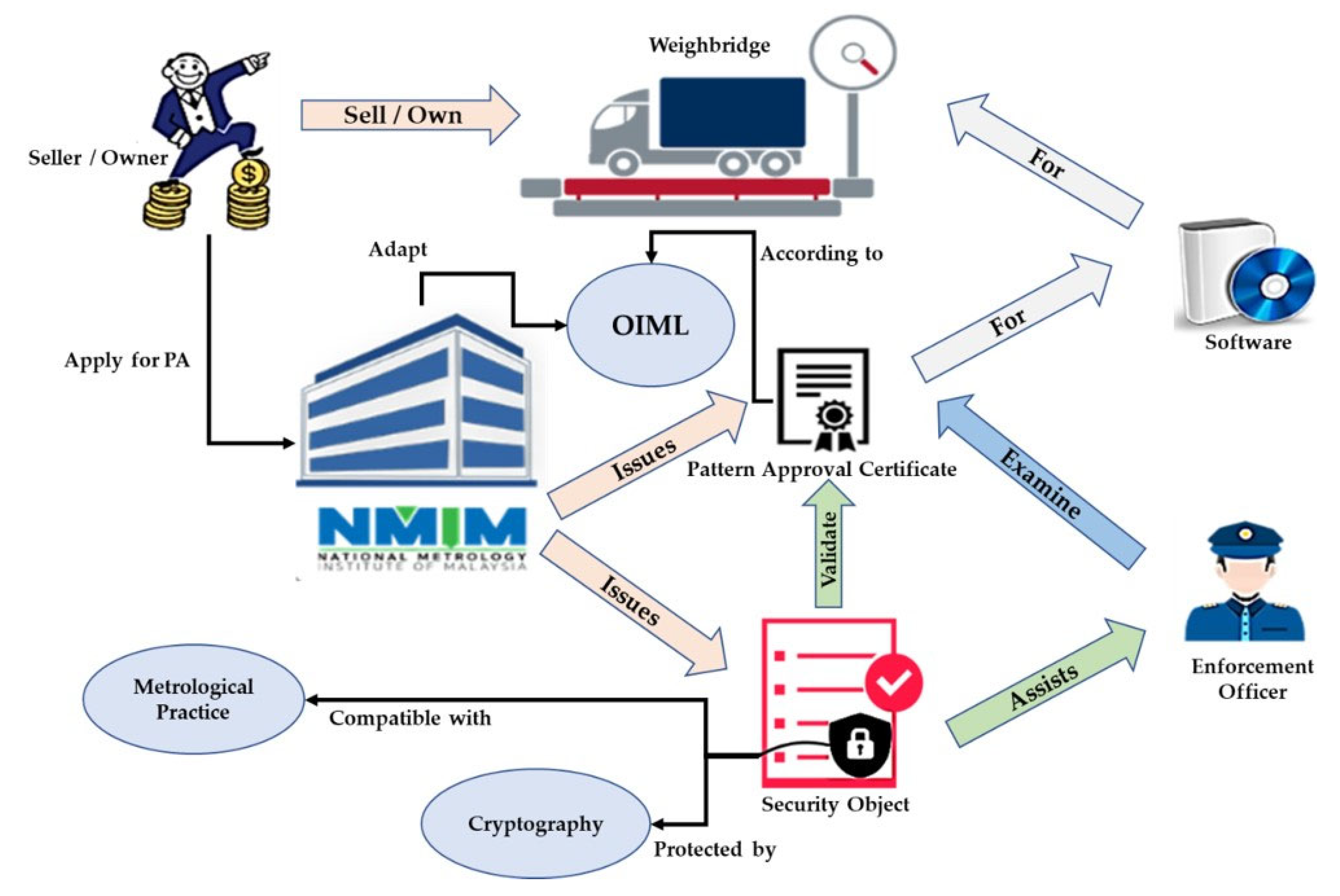
2.1. Security Evaluation in Legal Metrology

In LM, risk analysis is used as a tool to evaluate the security of a designed system or instrument. In a recent study, a method based on ISO/IEC 27005, 15408, and 18045 was developed by Esche and Thiel [9] to provide the foundation of security analysis in LM domain. However, this technique justifies the security of measuring instruments based merely on the device’s technical features alone.
This method later was improved by incorporating the attacker’s motivation. It was performed by integrating an attack tree modeling as part of the evaluation framework which is known as Attack Probability Tree (AtPT) [10].

2.2. Attack Tree

An attack tree is a model for visualizing and analyzing potential security threats [11]. This method has been adopted by the North Atlantic Treaty Organization (NATO) as well as the Open Web Application Security Project (OWASP) [12]. Several studies have been conducted by integrating attack trees with risk management methodologies such as supervisory control and data acquisition (SCADA), radio-frequency identification (RFID), and automated teller machine (ATM).
ATSyRA [13] made an approach by extracting a defined filter structure from an expert. This allows the semantic domain and structure of the filter to be found without intervention from experts. However, this method has imperfect (informal) label structure.
TREsPASS [14] applies the security knowledge base to the attack tree generated from the model system. However, the generic IT security knowledge base is incompatible for the LM situation.
Another formal design methodology is ADTool [15]. This method adopts the ADTree-based attack tree concept [16]. However, ADTree has a different approach with two types of players: strikers and defenders. This methodology, however, is not compatible with the AtPT scoring semantics used in the LM based on ISO/IEC 18045.
Attack tree design is a subjective procedure according to [17]. Esche in [10] emphasizes that in the field of LM, all measuring instruments share the same basic characteristics. Based on the fact that all instruments are based on the same technical solution it should be that the diversity of attack tree designs produce the same results.
Although the attack tree design is considered simple and intuitive, there is room for conceptual errors and a diversity of interpretations regarding the semantic refinement of the tree. Thus, there lack of best practices in tree structure and comprehensive tree design.

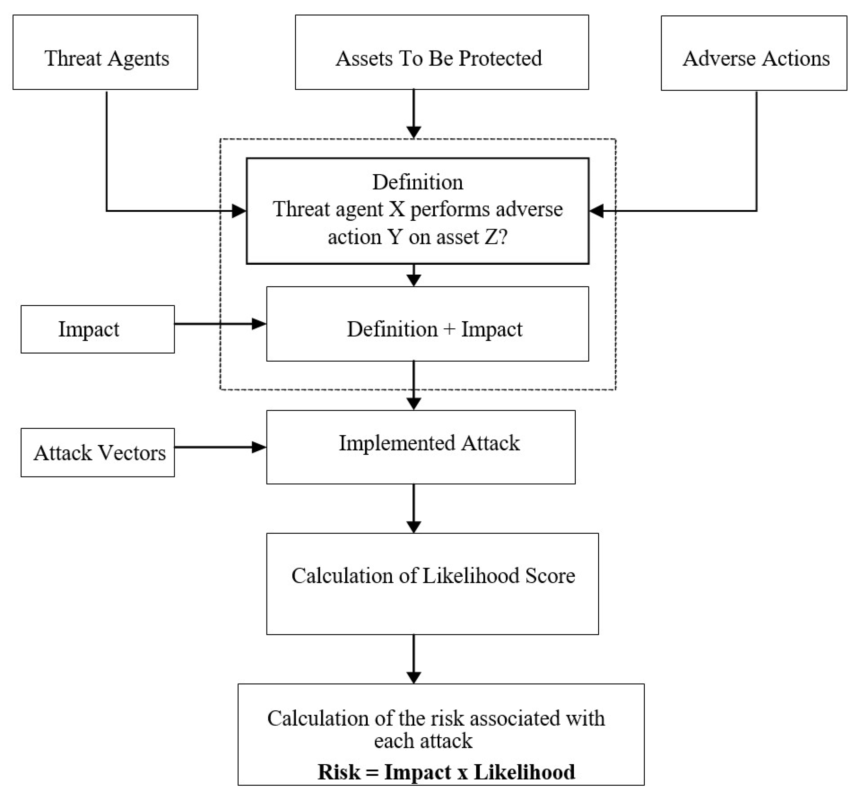
3. Research Methodology

Attack tree design in an AtPT framework is enhanced in this study where formal notation replaces the original version used only text to the name for each node [18]. We also improved the attack tree by adapting the SAND operator where the original model did not have it.
The attack tree decoration phases are formalized in mathematical notation in both the attack tree domain and finite state transition domain. This is to validate the correctness properties by using a method introduced by [19].
Table 1 shows the important notations that are used in the study.

3.1. Finite State Transition

Prop is a set of propositions containing all the variables representing a situation at one time. This Prop is in the form of ι, γ to denote the state before (ι) and after an event (γ). In this context the event is an attack vector υ.
A state transition system is a tuple Տ = (S, →, λ), where S is the finite transition set (elements of s, si) for i ∈ ℕ while → ⊆ S×S is the transition relation to the system and assumed to be the left total. The λ: Prop → 2S is the labeling function. A state s is labelled as p when s ∈ λ (p) and the size of S is |S | = |S | + |→|.
A path in system S is the state condition where it has non-empty sequences of states. The symbols such as π and ρ are used to depict the paths. A cycle in paths πΠ(Տ) is a factor of π′ of π where π′(0) = π′(|π′|).
An elementary path is a path which has no cycle. A path π which is elementary, does not have any state that more than once. Therefore, |π| ≤ |Տ|, removing all the cycles from π iteratively until the resulting path is non-elementary. Table 2 summarizes the attack tree critical analysis.

3.2. Formalizing Attack Tree

In conjunction with the analysis of AtPT methodology [20], attack vector υ for attack tree T over a set of attack vector attributes (Table 3) is the refinement for the path π from with the direction from ι to γ. Assuming υ ∈ →, where υ1, υ2,…υn is the attack vectors for each T1, T2,…Tn, for 1 ≤ in. The size of attack vector is |υ| = |T | ∋ ∀ Tnυn. The attack vector evaluation consists of conditions OP ∈ {OR, AND, SAND) and has the number of arity n ≥ 2. The main goal of a an attack vector υ is γ where the original state is ι and where the operator is OP. The attack tree can be represented in the form of T = (⟨ι, γ⟩, OP)(T1, T2,…Tn). Where the size of an attack tree |T| is the number of attack vectors in T such that |⟨ι, γ⟩| = 1 and |(⟨ι, γ⟩, OP)(T1, T2,…Tn)| = 1 + i = 1 n T i .
Let the set of attributes α = {Du, Ex, Kn, Wn, Eq} for all υ1, υ2,…υn be the attack vectors for T1, T2,…Tn. While the be the AtPT risk scoring calculation based on the OP over the set α. Therefore, υ i = Ɽ (OP, α) where, OP ∈ {OR, AND, SAND | 1 ≤ in }.

3.3. Attack Tree Correctness Property

According to [21], an attack tree is considered to have the meet property when:
OP(⟨ι1,γ1⟩, ⟨ι2,γ2⟩,…⟨ιn,γn⟩)⟧Տ ∩ ⟦ ⟨ι,γ⟩ ⟧Տ ≠ ∅
While undermatch property has:
OP(⟨ι1,γ1⟩, ⟨ι2, γ2⟩,…⟨ιn, γn⟩)⟧Տ ⊆ ⟦⟨ι,γ⟩⟧Տ
And overmatch reflects:
OP(⟨ι1,γ1⟩, ⟨ι2,γ2⟩,…⟨ιn,γn⟩)⟧Տ ⊇ ⟦⟨ι,γ⟩⟧Տ
Finally, the match property is:
OP(⟨ι1,γ1⟩, ⟨ι2,γ2⟩,…⟨ιn,γn⟩)⟧Տ = ⟦⟨ι,γ⟩⟧Տ
In other words, the meet property is a minimum property for an attack tree before further analysis can be performed. This proves that at least one path can achieve the main goal and its refinements. This feature indicates that this tree model is essentially considered to be correct, and researchers can already begin to estimate the security of a system.
Undermatch shows that all paths that meet the refinement of a node also meet the goal itself. It can be considered as an underestimate for a set of scenarios and is enough to find the weaknesses of a system. While overmatch, on the other hand indicates that all paths that achieve the root node goal also met all decomposition to sub-goals. This is an assumption. If the tree characteristics are found to be a match, then it is considered that a tree has one hundred percent similarity with the system analyzed.
A tree should have a minimum of admissible and meet features for a tree design to be considered correct with respect to the analyzed systems.

4. Malaysian NAWI Software Inspection for Computer

Malaysia Software-Assisted Non-Automatic Weighing Instrument Inspection (MySANI) is a proposed method designed to enhance the inspection process within the framework of the LM ecosystem in Malaysia as depicted in Figure 2 [22]. It consists of two parts, which are PA and market surveillance.
In Malaysia, PA is stated in the Weights and Measures Act 1972 (Act 71) and the National Measurement System Act 2007 (Act 675). The PA is provided for the National Measurement Standard Laboratory (NMSL) to carry out inspection and evaluation activities of measuring equipment [23,24]. Each measuring equipment has its own set of rules and laws enforced by specialized government enforcement agencies. For example, smoke meters, axel scales, and speed traps are enforced by the Road and Transport Department. Meanwhile measuring instruments for trade purposes are under the jurisdiction of Ministry of Trade and Consumer Affairs. PA covers all trade and law enforcement activities to ensure that the instruments meet the requirements of legal and international standards. It also ensures that measurement accuracy, fair trade, and law enforcement function well in all environmental conditions and situations [25]. The instrument was tested and evaluated from various physical aspects in a variety of conditions, including software functionalities [26].
Illegal usage of software for NAWI is detected in the market during market surveillance once the pattern is approved [27]. This activity is carried out by regular inspections such as by a government-appointed third-party organization (as in the current situation). There are three elements to be checked on NAWI software during market surveillance:
  • Printed certificate/hard copy certificate (HC) information;
  • Certificate–software pairing is correct;
  • Legally relevant (LR) part of the software is intact.
If any of these stated elements are in doubt, the surveillance check is considered failed. The enforcement officer can take further steps such as sealing the whole system and seizing the whole measuring instrument system for further investigation.
The details of MySANI workflow during pattern approval and for market surveillance are depicted in Figure 3 and Figure 4, respectively.

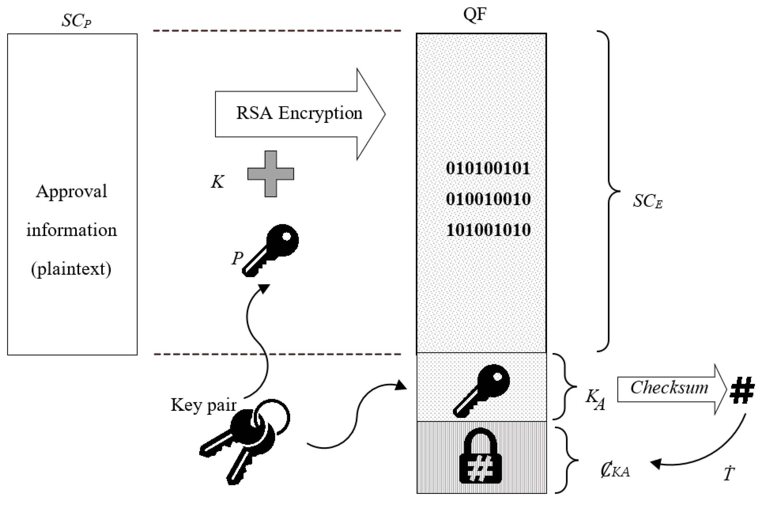
4.1. Security Object

To achieve the aforementioned objectives, security objects (SOs) are implemented within the MySANI method. SOs consist of two parts: (1) soft-certificate plaintext (SCP); and (2) quasi file (QF) [5]. Figure 5 illustrates the components of the security object which are used in MySANI.
  • Transformed polynomial checksum for ȻKA;
  • Plain checksum ČLR for LR module which are recorded inside the SCP.
QF is designed as the security carrier to the SCP. It protects the information contained from modification. Attacks on the SCP merely be focus on the QF security features. QF gathers several sections of data into single file. It consists of three main parts: ciphered soft certificate SCE, public key KA, and the checksum of KA with a hidden polynomial ȻKA. The SCP is encrypted using the RSA private key KP to become SCE. KA and KP are generated by National Metrology Institute of Malaysia (NMIM) during certification process. KP is not disclosed and is only known by NMIM. The QF = {SCE, KA, ȻKA} consists of three sub-components as described in Table 4.
Let decr decryption and encr be the encryption function, KA as public key and KP as private key. SCE is the ciphered text of SCP. Therefore, SCP = decr(SCE, KA) = decr(encr(SCP, KP), KA) is the plaintext certificates which contain approval information that is important for inspection. It contains some of the plaintext information of static HC without security features ∀SCPSCP ⊆ HC where it uses an XML format based on the proposed DCC format [28].

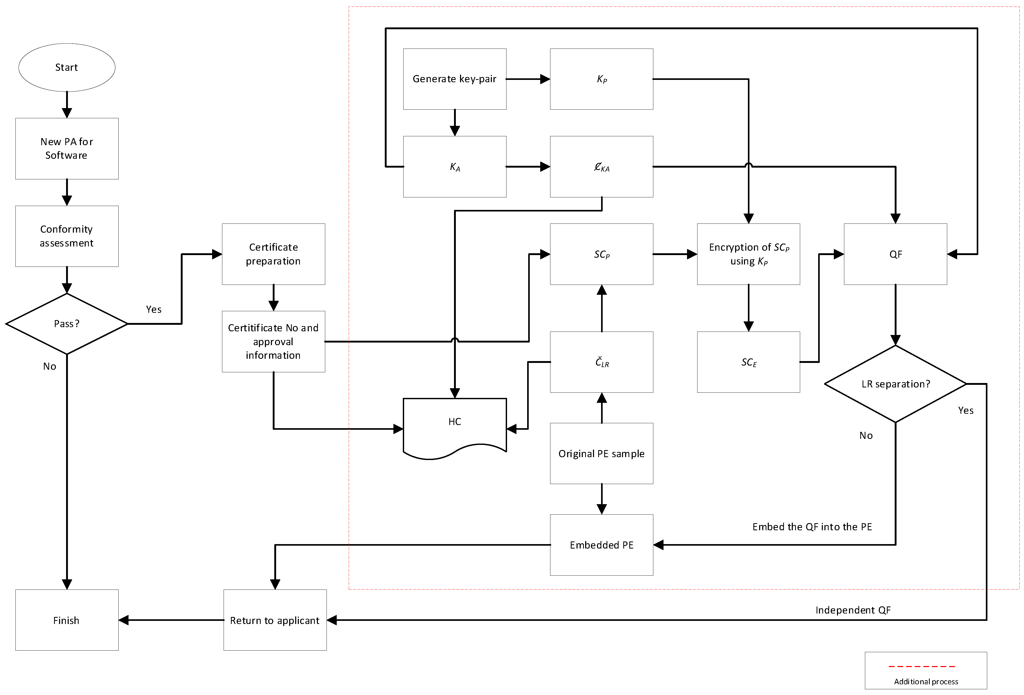
4.2. Process Workflow

During the PA certificate preparation stage, the certificate number and approval of related information along with the important information are used in the preparation of the SCP. The information in this is important and sufficient for field inspection purposes. This SCP is then encrypted for the QF preparation process at the later stage. The checksum for the LR module Č is generated for the purpose of printed certificate HC preparation. Some important information is used in the preparation of the SCP. The information in this is important and sufficient for field inspection purposes. This SCP is then encrypted for the QF preparation process at a later stage. Table 5 shows the information inside the plaintext certificate.
The MySANI workflow during pattern approval is shown in Figure 3. After a software passes the conformity assessment, while the certificate and approval information are being prepared for printed certificate HC, a pair of keys consisting of KA and private key KP are generated. The polynomial Ȼ for KA is also calculated and placed inside HC. The soft certificate plaintext SCP contains approval information as well as the plain checksum for legally relevant module Č. The SCP is then encrypted by using KP and becomes the ciphered certificate SCE. The three elements (SCE, KA and ȻKA) are then combined to form the QF. The QF is passed to the applicant or undergoes an embedding process to its main executable (ME) depending on the approval mode for distribution.
A special tool, MySANI inspection software (MySANI-IS), is developed to assist the enforcement officer to verify the security objects. The MySANI first tries to locate the QF; whether it is embedded within the main executable ME or as a standalone QF file. If it is embedded, then extraction procedures are performed to pull out the QF out of the ME. The QF is then extracted into three parts: SCE, KA, and ȻKA. The ȻKA is used to determine the key’s integrity and authenticity before it is used to extract the SCE to form the SCP. The approval information is then extracted from the SCP and is displayed to the examiner for inspection. The plain Č is used to determine whether the legally relevant part of the software is intact or not.

4.3. Polynomial Transformation

The polynomial transformation Ť = {St1, St2, ƭ} is an algorithm function to generate a checksum with hidden polynomial Ȼ instead of a standard plain checksum Č, for alignment with the LM requirements. Ť is realized by first calculating the checksum of two concatenated strings (St1 and St2) to become the Ȼ′ and then performing bitwise XOR off the resulting checksum with secret bytes ƭ.
ČKA is the unknown plain checksum of KA where Ť(KA, SS, ƭ): ČKAȻKA. The ȻKA is in different form of ČKA with equivalent strength of the checksum algorithm such that ČKAȻKA. Any modification that changes ČKA also changes the ȻKA.
ȻKA′ checksum is calculated over the concatenated string of j = KASS, where SS is secret string and j contains both strings in the form of st1 and st2 where the st1 is the string of KA while st2 is the string SS such that KASS = {st1 st2: st1KA, st2SS}. Then, ȻKA′= crcf (j) and ȻKA = ČKA′⊕ ƭ. The ȻKA′ can be retrieved back for integrity comparison purposes by ȻKA′= ČKAƭ.
Information within the SCP is retrieved back and displayed to the inspector during market surveillance to confirm the correctness of the printed certificate information. Inspection is considered failed if the information displayed within SCP is not the same as the information on the printed certificate.
The checksum of the legally relevant software is generated (ČLR′) in real time for the purpose of comparison with the stored ČLR to check the integrity of the legally relevant module. Let the extr be the QF extraction function such that ((ČLR′ = ČLRextr(QF)) ∧ (¬ČLR′ = ČLR))→FAIL!.

5. Modelling Attack Scenario for MySANI

The attack tree is used to visualize the attack vectors that an attacker might perform. In order to model an attack tree, an attack scenario is required to be established in the first place. The attack scenario describes how the attacker might access the protected information and try to fake the information within the SO.
In this simulation, the attacker’s main target is to modify the content of QF. The attacker himself is the owner of the software and indirectly also owns the QF (worst case scenario). The attacker has unrestricted access to the target artifact. The attacker is assumed to already possess MySANI-IS used by the inspector as the second target of attack.
The attacker realizes that the KP is required to encrypt back the amended SCP′. Since the key pair uses the RSA algorithm and the original KP is not placed in the inspection’s software, the only way is by generating the fake private key pair of KP′ and the fake public key of KA′. KP′ is used to re-encrypt SCP′ while KA′ is placed back into QF replacing the original KA.
In order for the status of the QF to remain valid during the field inspection, the attacker must find a way to perform reverse engineering on the software used by the inspector to obtain the Ť algorithm which protects the KA as part of QF. Suppose the attacker succeeds in breaking the Ť algorithm: in that case, the attacker can recalculate the fake hidden polynomial Ȼ′ and once again, the attacker can reconstruct the fake QF (QF′) by reassembling the above three parts, namely SCP′, KA′ and Ȼ′. If this happens, the inspection is in valid status even if the QF’s contents are changed. The inspector is not able detect the irregularities of the QF.
The analysis is started by studying the attack vectors on QF. An attacker will not carry out an attack motivated by damaging or destroying the availability of the QF or altering any QF structure as this causes the status check to fail and the enforcement officer may immediately seize the entire system for further investigation.

5.1. Attack Simulation

The root of the attack tree is υt, when it is the ultimate goal for the attacker with intention to fake the QF with fabricated information and leave no trace of evidence during the market surveillance inspection. The tree consists of three main branches (υ1, υ2, and υ3). Attack vector υ1 is about obtaining the QF, attack vector υ2 is about modifying the content, while υ3 is about hiding the trace. Figure 6 shows the attack tree designed for the simulation. The details of each of attack vector is described in Table 6.

5.2. Security Object State Modelling

The formal validation method is performed by using a finite state transition system to validate the attack tree T design model. Before analysis can be performed, the attack tree must also be presented in the form of formal notation.
Q = {Q, Q+, Qg, Qt}: This variable specifies the state of QF. Where, Q indicates the state where the attacker does not have QF and it is embedded in the ME target of evaluation (TOE), Q+ indicates the state of the attacker does not have QF and is in the form of an individual file, Qg is the state where the attacker already has QF and is ready for attack, and Qt is the state where the attacker rearranges the QF with false elements.
PKey = {NaC, AcG, AcF}: This variable specifies the state of public key. NaC indicates the attacker does not yet obtain the original public key KA, AcG indicates the original public key of the KA is successfully obtained, and AcF the situation where the attacker generates and possesses a fake key pair.
SCP = {Up, Oe, Oc}: This variable indicates the condition of plaintext certificate. It consists of three states: Up is the situation where the SCP plaintext soft certificate is not opened, Oe is the situation where the SCP plaintext soft certificate is successfully opened, and Oc is the situation where the SCP plaintext soft certificate is amended with fake information.
TpRev = {tt, ff} is the variable which indicates the states of Ť algorithm cracks, whether the attacker successfully cracks the algorithm (tt) or not (ff).

5.2.1. State Transition Modelling

Let the Ƶ system consist of two parties, namely the attacker and the QF. The system is modeled using a state variable, i.e., where its value determines the configuration possibilities for the system. In the initial settings, the attacker is assumed to not yet have a QF and intends to attack the QF by modifying the SCP without being able to be detected by the inspecting officer. To model the dynamic properties for the system, let the system be (zi−1, zi) ∈→, for every 1 ≤ i ≤ 9. For the initial condition for the QF, q = (Q =Q) ∨ (Q =Q+) while the q′ = (Q =Qg) ∨ (Q =Qt) and z0, z1 ∈ λ (q). For each state zi ∈ λ (q′) for 3 ≤ i ≤ 9.
The path ρ, shows the scenario for the attacker to execute an attack from the beginning of the situation to the end of the goal in the ρ system. Table 7 summarized the state transition.
For the transition system, only one variable changes at a time. z0 indicates a situation where the QF is not yet owned, is embedded, and needs to be extracted into an individual file, the attacker does not have any cryptographic keys, while the content of the soft certificate are in its original form. The state can be represented as Q = Q while the PKey = NaC, z0, z1 ∈ λ (q) and TpRev = ff.
The transition is as follows:
  • z1 is the same as z0 but QF is in the form of a separate file that needs to be identified by the attacker. The Q = Q+ state transition occurs;
  • z2 is the same as z0 but QF is successfully owned by the attacker. The Q = Qg state transition occurs;
  • z3 is the same as z2 but the attacker managed to obtain the KA public key from the QF element. The PKey = AcG state transition occurs;
  • z4 is the same as z3 but this time the attacker managed to open the SCP by decrypting the SCE using KA. The ScP = Op state transition occurs;
  • the z5 is the same as the z4 but the attacker generates a fake key pair that matches the original public key configuration. The following PKey = AcF variable change occurs;
  • z6 is the same as z5 but the attacker amended SCP to SCP′. The ScP = Oe variable values are changed;
  • z7 is the same as z6 but the attacker encrypted SCP′ using fake private key. The ScP = Oc values are changed;
  • z8 is the same as z7 except at this point the attacker successfully cracked the Ť algorithm, TpRev = tt;
  • And finally, z9 is the same last state as the z8 but the attacker reformed the QF with fake elements Q = Qt.

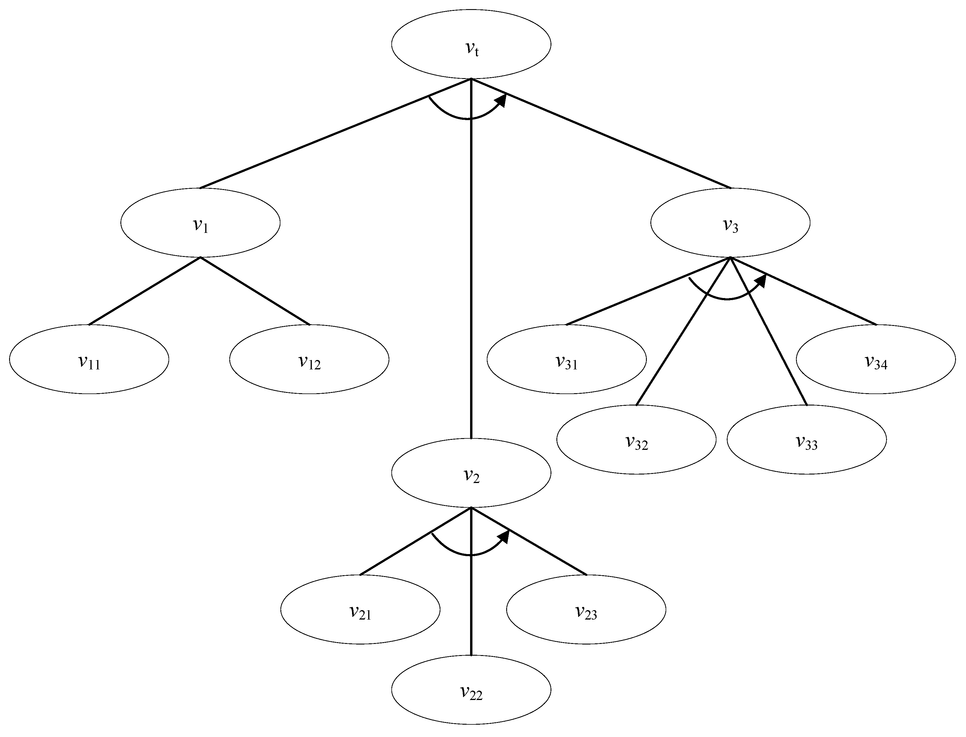
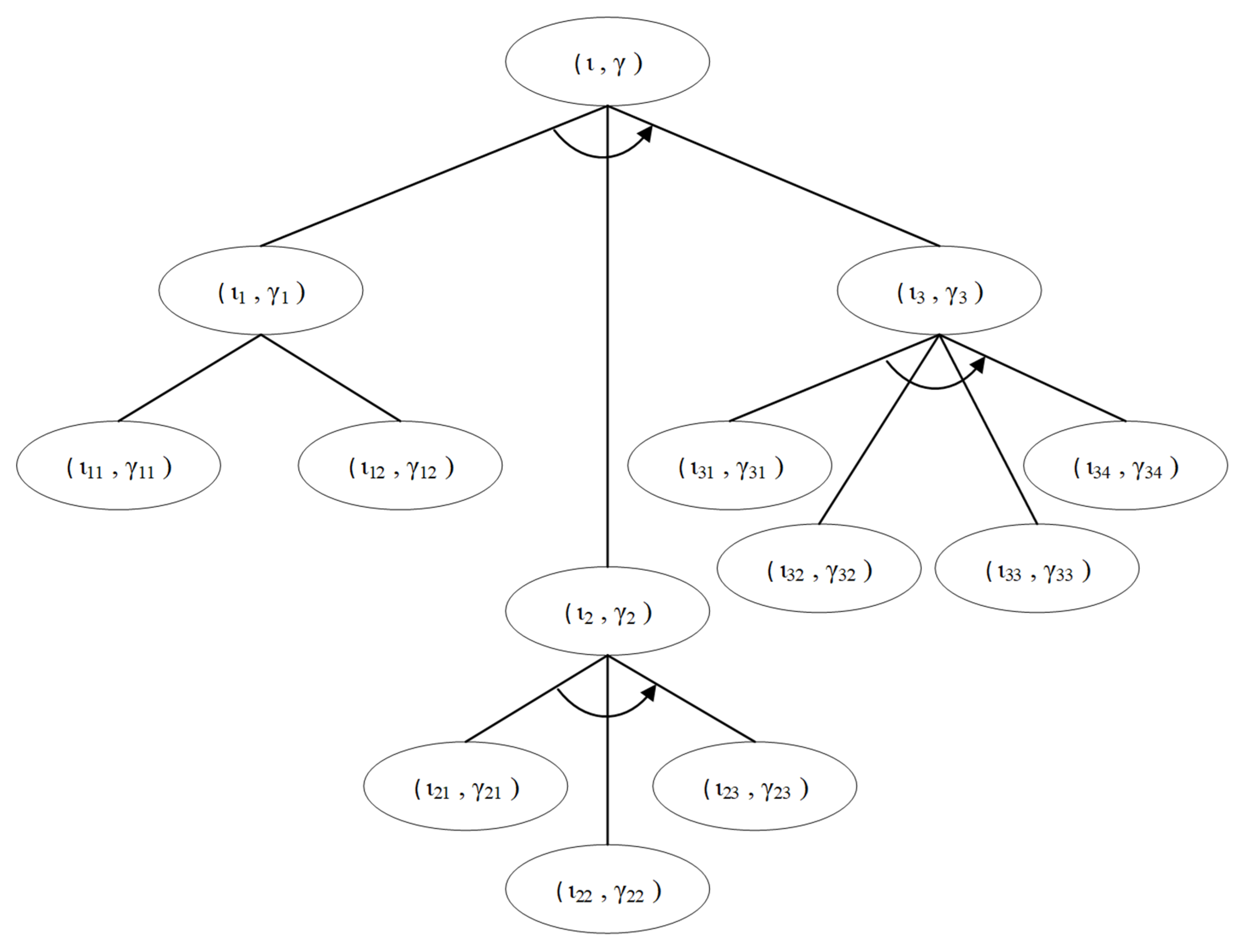
5.2.2. Attack Tree Formal Modelling

A similar attack is being modeled as attack tree T for the system Ƶ as discussed, which has a goal in the form T = (⟨ι, γ⟩, SAND)(T1, T2, T3). Where the formal representation of each sub-tree:
T1 = (⟨ι1,γ1⟩), OR)(⟨ι11,γ11⟩,⟨ι12,γ12⟩);
T2 = (⟨ι2,γ2⟩), SAND)(⟨ι21,γ21⟩, ⟨ι22, γ22⟩, ⟨ι23,γ23⟩);
T3 = (⟨ι3, γ3⟩), SAND)(⟨ι31, γ31⟩,⟨ι32, γ32⟩,⟨ι33, γ33⟩, ⟨ι34, γ34 ⟩).
Each sub-tree Ti has the atomic goal in the form of ⟨ιi, γi⟩. The same variables are applied to the state transition notation. Figure 7 shows the attack tree with formal notations.
For the formal model the attack tree is as follows:
  • The original situation is where the attacker does not yet have a QF, does not have a public key, is not able to access plaintext soft certificates, and did not successfully crack the Ť algorithm.
    ι:= (Q = Q) ˄ (PKey = NaC) ˄ (ScP = Uo) ˄ (TpRev = ff);
  • The ultimate goal for the attacker is to be able to amend the plaintext soft certificate, possess a fake key pair, re-encrypt using a fake private key, and put a fake public key back in the amended QF.
    γ:= (Q = Qt) ˄ (PKey = AcF) ˄ (ScP = Oe);
  • Atomic target ⟨ι1, γ1⟩: In the original state, the attacker does not yet have QF and needs to identify a QF as the target first. The goal is to have the QF in the form of individual file. Assuming ⊤ represents an empty configuration, therefore:
    ι1:= ⊤ and γ1:= (Q = Qg);
  • Atomic goals ⟨ι11, γ11⟩: QF is embedded in the ME and the attacker must first extract it into a single file. Therefore:
    ι11:= (Q = Q) and γ11 = γ1;
  • Atomic goals ⟨ι12, γ12⟩: QF is available as an individual file. The attacker needs to identify the location of the QF file. Therefore:
    ι12:= (Q = Q+) and γ12:= (Q = Qg);
  • Atomic goal ⟨ι2, γ2⟩: The attacker aims to modify the SCP in the QF. Therefore:
    ι2:= (Q = Qg) ∧ (PKey = AcG) ∧ (ScP = Uo) ∧ (TpRev = ff) and γ2:= γ;
  • Atomic goal ⟨ι21, γ21⟩: Attacker obtains KA. Therefore:
    ι21:= (Q = Qg) ∧ (PKey = NaC) and γ21:= (PKey = AcG);
  • Atomic goal ⟨ι22, γ22⟩: Attacker decrypts SCE using KA. Therefore:
    ι22:= γ21 and γ22:= (ScP = Op);
  • Atomic goal ⟨ι23, γ23⟩: Attacker modifies the contents of the SCP. Therefore:
    ι23:= γ22 and γ23:= (ScP = Oe);
  • Atomic goal ⟨ι3, γ3⟩: The attacker aims to reconstruct the QF using modified plaintext data and fake keys. Therefore:
    ι3:= (PKey = AcF) ∧ (ScP = Oe) ∧ (TpRev = ff) and γ3:= γ;
  • Atomic goal ⟨ι31, γ31⟩: Attacker generates fake KP′. Therefore:
    ι31:= ⊤ and γ31:= (PKey = AcF);
  • Atomic goals ⟨ι32, γ32⟩: The attacker encrypts the SCP′ by using fake key KP′. Therefore:
    ι32:= (PKey = AcF) ∧ (ScP = Oe) and γ32:= (ScP = Oc);
  • Atomic goals ⟨ι33, γ33⟩: Attack polynomial transformations based on KP′ and SCP. Therefore:
    ι33:= (TpRev = ff) and γ33:= (TpRev = tt);
  • Finally, the atomic goal ⟨ι34, γ34⟩: The attacker reconstructs all elements into a false QF. Therefore: ι34:= (PKey = AcF) ∧ (ScP = Oe) ∧ (TpRev = tt) and γ34:= γ3.

5.3. Formal Analysis and Discussion

T1 is defined as ⟦⟨ι1, γ1⟩⟧Տ while for the sub-trees, are ⟦⟨ι11, γ11⟩⟧Տ and ⟦⟨ι12, γ12⟩⟧Տ, respectively. Therefore, because of ⟦OR(⟨ι11, γ11⟩, ⟨ι12, γ12⟩)⟧Տ = ⟦⟨ι11, γ11⟩⟧Տ ∪ ⟦⟨ι12, γ12⟩⟧Տ while ⟦⟨ι1, γ1⟩⟧Տ ∩ ⟦OR(⟨ι11, γ11⟩, ⟨ι12, γ12⟩)⟧Տ ≠ ∅, then the tree is considered to have the meet property.
Since the ⟦OR(⟨ι11, γ11⟩, ⟨ι12, γ12⟩)⟧Տ ⊇ ⟦⟨ι1, γ1⟩⟧Տ, thus the T1 is also has the overmatch property.
For T2, it is defined as ⟦⟨ι2, γ2⟩⟧Տ and all the sub-trees can be refined as ⟦ SAND(⟨ι21, γ21⟩, ⟨ι22, γ22⟩, ⟨ι23, γ23⟩)⟧Տ; therefore, the sub-trees are equivalent to ⟦⟨ι21, γ21⟩⟧Տ ⋅ ⟦⟨ι22, γ22⟩⟧Տ ⋅ ⟦⟨ι23, γ23⟩⟧Տ. From a quick analysis, the ⟦SAND(⟨ι21, γ21⟩, ⟨ι22, γ22⟩, ⟨ι23, γ23⟩)⟧Տ ≠ ∅ and thus, T2 is considered to have the meet property. Moreover, ⟦SAND(⟨ι21, γ21⟩, ⟨ι22, γ22⟩, ⟨ι23, γ23⟩)⟧Տ = ⟦⟨ι2, γ2⟩⟧Տ; therefore, T2 also has the match property.
For the last branch T3, ⟦⟨ι3, γ3⟩⟧Տ where the sub-trees can be refined as ⟦SAND(⟨ι31, γ31⟩, ⟨ι32, γ32⟩, ⟨ι33, γ33⟩, ⟨ι34, γ34⟩)⟧Տ where it is equivalent to ⟦⟨ι31, γ31⟩⟧Տ ⋅ ⟦⟨ι32, γ32⟩⟧Տ ⋅ ⟦⟨ι33, γ33⟩⟧Տ ⋅ ⟦⟨ι34, γ34⟩⟧Տ. By removing non-elementary paths ⟦⟨ι3, γ3⟩⟧Տ ∩ ⟦SAND(⟨ι31, γ31⟩, ⟨ι32, γ32⟩, ⟨ι33, γ33⟩, ⟨ι34, γ34⟩)⟧Տ ≠ ∅. Thus, the T3 has the meet property and since ⟦⟨ι3, γ3⟩⟧Տ = ⟦SAND(⟨ι31, γ31⟩, ⟨ι32, γ32⟩, ⟨ι33, γ33⟩, ⟨ι34, γ34⟩)⟧Տ; therefore, T3 also has the match property.
For the final path semantics of goal expression T, ⟦⟨ι, γ⟩⟧Տ, can be refined as ⟦SAND(⟨ι1, γ1⟩, ⟨ι2, γ2⟩, ⟨ι3, γ3⟩)⟧Տ and is equivalent to ⟦⟨ι1, γ1⟩⟧Տ ⋅ ⟦⟨ι2, γ2⟩⟧Տ ⋅ ⟦⟨ι3, γ3⟩⟧Տ. By removing non-elementary paths, similar to the previous sub-trees, ⟦⟨ι, γ⟩⟧Տ ∩ ⟦ SAND(⟨ι1, γ1⟩, ⟨ι2, γ2⟩, ⟨ι3, γ3⟩)⟧Տ ≠ ∅, thus the T has the meet property and ⟦⟨ι, γ⟩⟧Տ = ⟦SAND(⟨ι1, γ1⟩, ⟨ι2, γ2⟩, ⟨ι3, γ3⟩) ⟧Տ; therefore, T has the match property.
Considering the main tree T = (⟨ι, γ⟩, SAND)(T1, T2, T3), and considering all the following sub-branches, the (⟨ι1, γ1⟩, OR)(T11, T12) ≠ ∅, (⟨ι2, γ2⟩, SAND)(T21, T22, T23) ≠ ∅ and (⟨ι3, γ3⟩, SAND)(T31, T32, T33, T34) ≠ ∅ as well as the main tree (⟨ι, γ⟩, SAND)(T1, T2, T3) ≠ ∅, the tree T is considered to have the Global Admissible property.
The design of attack tree T is found to be consistent and correct with respect to the system Ƶ in its finite transition system domain. Each of the sub-trees have match property except the sub-tree T1, which has the overmatch property. This however does not affect the overall security features of QF since all the sub-branches of T relate to OP = SAND thus complementing each other. Thus, the attack tree T modelling can be used to further analyze the security features of QF.

6. Conclusions

This paper discussed MySANI, the enhanced method in regulating the software used for NAWI within the LM framework in Malaysia. This method is realized by introducing QF, which is used as a secondary information source of LR information of the TOE and secured via public cryptography. The security design is validated by using attack tree modelling where the attack tree is described using formal notation and the correctness validation is achieved via comparison against the finite state transition system. As part of security analysis in LM, this paper also demonstrated the possibility of the formalization design of attack tree before it could be integrated with the AtPT framework analysis. This enables the attack tree to be verified prior to further security risk analysis evaluation. The issue of scalability is not studied in this paper due to the nature of the LR part of NAWI, which is usually very small. However, in the future, if the security objects in this paper are to be implemented for other types of measuring instruments, the scalability issues of the formal method approach might be considered.

Author Contributions

Conceptualization, M.A.I. and F.Q.; Funding acquisition, Z.S.; Methodology, N.Z.; Supervision, N.M.; Visualization, Z.S.; Writing—original draft, M.A.I. and N.Z.; Writing—review and editing, F.Q., N.M. and M.U.S. All authors have read and agreed to the published version of the manuscript.

Funding

This paper is supported by the Universiti Kebangsaan Malaysia Grant Number: KKP/2020/UKM-UKM/4/3.

Data Availability Statement

Not applicable.

Acknowledgments

The authors would also like to thank the respected editor and reviewer for their support.

Conflicts of Interest

The authors declare no conflict of interest.

References

  1. O’Brien, M.T.; Schuh, J.C.L.; Wancket, L.M.; Cramer, S.D.; Funk, K.A.; Jackson, N.D.; Kannan, K.; Keane, K.; Nyska, A.; Rousselle, S.D.; et al. Scientific and Regulatory Policy Committee Points to Consider for Medical Device Implant Site Evaluation in Nonclinical Studies. Toxicol. Pathol. 2022, 50, 512–530. [Google Scholar] [CrossRef] [PubMed]
  2. Doe, J.; Van de Wetering, R.; Honyenuga, B.; Versendaal, J. Eco-system oriented instrument for measuring firm technology adoption. In Proceedings of the 19th International Conference on Electronic Busines, Newcastle Upon Tyne, UK, 8–12 December 2019. [Google Scholar]
  3. Ghazvini, A.; Shukur, Z. Review of information security guidelines for awareness training program in healthcare industry. In Proceedings of the 2017 6th International Conference on Electrical Engineering and Informatics (ICEEI), Langkawi, Malaysia, 25–27 November 2017; pp. 1–6. [Google Scholar]
  4. Schwemer, S.F. Article 17 at the Intersection of EU Copyright Law and Platform Regulation. Nord. Intellect. Prop. Law Rev. 2020, 1, 400–435. [Google Scholar]
  5. Said, I.O.; Shukur, Z.; Bin Ibrahim, M.A. A certification criteria for software of measuring instruments based on Malaysian environment. In Proceedings of the 2017 6th International Conference on Electrical Engineering and Informatics (ICEEI), Langkawi, Malaysia, 25–27 November 2017; pp. 1–5. [Google Scholar]
  6. Sahlabadi, M.; Muniyandi, R.C.; Shukur, Z.; Qamar, F. Lightweight Software Architecture Evaluation for Industry: A Comprehensive Review. Sensors 2022, 22, 1252. [Google Scholar] [CrossRef] [PubMed]
  7. Verdon, D.; McGraw, G. Risk analysis in software design. IEEE Secur. Priv. 2004, 2, 79–84. [Google Scholar] [CrossRef]
  8. Talabis, M.; Martin, J. Information Security Risk Assessment Toolkit: Practical Assessments through Data Collection and Data Analysis; Newnes: Boston, MA, USA, 2012. [Google Scholar]
  9. Esche, M.; Thiel, F. P7.4—Incorporating a measure for attacker motivation into software risk assessment for measuring instruments in legal metrology. In Proceedings of the 18th GMA/ITG-Fachtagung Sensoren und Messsysteme 2016, Nuremberg, Germany, 10–11 May 2016; Volume 1, pp. 735–742. Available online: https://www.ama-science.org/proceedings/details/2436 (accessed on 10 January 2023).
  10. Esche, M.; Toro, F.; Thiel, F. Representation of attacker motivation in software risk assessment using attack probability trees. In Proceedings of the 2017 Federated Conference on Computer Science and Information Systems (FedCSIS), Prague, Czech Republic, 3–6 September 2017; pp. 763–771. [Google Scholar]
  11. Meng, B.; Larraz, D.; Siu, K.; Moitra, A.; Interrante, J.; Smith, W.; Paul, S.; Prince, D.; Herencia-Zapana, H.; Arif, M.; et al. VERDICT: A Language and Framework for Engineering Cyber Resilient and Safe System. Systems 2021, 9, 18. [Google Scholar] [CrossRef]
  12. Audinot, M.; Pinchinat, S.; Kordy, B. Guided design of attack trees: A system-based approach. In Proceedings of the 2018 IEEE 31st Computer Security Foundations Symposium (CSF), Oxford, UK, 9–12 July 2018; pp. 61–75. [Google Scholar]
  13. Pinchinat, S.; Acher, M.; Vojtisek, D. ATSyRa: An integrated environment for synthesizing attack trees. In Proceedings of the International Workshop on Graphical Models for Security, Verona, Italy, 13 July 2015; Springer: Berlin/Heidelberg, Germany, 2015; pp. 97–101. [Google Scholar]
  14. Pieters, W.; Hadziosmanovic, D.; Lenin, A.; Montoya, L.; Willemson, J. TREsPASS: Plug-and-play attacker profiles for security risk analysis. IEEE Secur. Priv. Poster Abstr. 2014, 1, 1–2. [Google Scholar]
  15. Kordy, B.; Kordy, P.; Mauw, S.; Schweitzer, P. ADTool: Security analysis with attack–defense trees. In Proceedings of the International conference on quantitative evaluation of systems, Buenos Aires, Argentina, 27–30 August 2013; pp. 173–176. [Google Scholar]
  16. Kordy, B.; Mauw, S.; Melissen, M.; Schweitzer, P. Attack–defense trees and two-player binary zero-sum extensive form games are equivalent. In Proceedings of the International Conference on Decision and Game Theory for Security, Berlin, Germany, 22–23 November 2010; pp. 245–256. [Google Scholar]
  17. Mauw, S.; Oostdijk, M. Foundations of attack trees. In Proceedings of the International Conference on Information Security and Cryptology, Seoul, Republic of Korea, 1–2 December 2005; pp. 186–198. [Google Scholar]
  18. Scala, N.M.; Goethals, P.L.; Dehlinger, J.; Mezgebe, Y.; Jilcha, B.; Bloomquist, I. Evaluating mail-based security for electoral processes using attack trees. Risk Anal. 2022, 42, 2327–2343. [Google Scholar] [CrossRef]
  19. Audinot, M.; Pinchinat, S.; Kordy, B. Is my attack tree correct? In Proceedings of the European Symposium on Research in Computer Security, Oslo, Norway, 11–15 September 2017; Springer: Berlin/Heidelberg, Germany, 2017; pp. 83–102. [Google Scholar]
  20. Schiele, N.D.; Gadyatskaya, O. A Novel Approach for Attack Tree to Attack Graph Transformation. In Proceedings of the International Conference on Risks and Security of Internet and Systems, Sousse, Tunisia, 7–9 December 2022; pp. 74–90. [Google Scholar]
  21. Yu, L.; Chen, K.; Chang, Y.; Chen, A.; Yin, Q.; Zhang, H. A New Correlation Model of IoT Attack Based on Attack Tree. In Proceedings of the 2021 IEEE Intl Conf on Dependable, Autonomic and Secure Computing, Intl Conf on Pervasive Intelligence and Computing, Intl Conf on Cloud and Big Data Computing, Intl Conf on Cyber Science and Technology Congress (DASC/PiCom/CBDCom/CyberSciTech), Calgary, AB, Canada, 25–28 October 2021; pp. 930–935. [Google Scholar]
  22. Manaf, M.R.A.; Nawi, A.M.; Tauhid, N.M.; Othman, H.; Rahman, M.R.A.; Yusoff, H.M.; Safian, N.; Ng, P.Y.; Manaf, Z.A.; Kadir, N.B.A.; et al. Prevalence of metabolic syndrome and its associated risk factors among staffs in a Malaysian public university. Sci. Rep. 2021, 11, 1–11. [Google Scholar] [CrossRef] [PubMed]
  23. Ibrahim, M.A.; Shukur, Z.; Zainal, N.; Marzuki, N.; Zakaria, O.; Yusof, M.M. Legalizing Software For Measuring Instruments: A Proposed Plan For Malaysian Case Study. Asia-Pac. J. Inf. Technol. Multimed. 2018, 9, 99–109. [Google Scholar] [CrossRef]
  24. Ibrahim, M.A.; Marzuki, N.; Shukur, Z.; Zainal, N. A Proposed Plan in Legalising Software for Measuring Instruments in Malaysia. In Proceedings of the 2018 Cyber Resilience Conference (CRC), Putrajaya, Malaysia, 13–15 November 2018; pp. 1–4. [Google Scholar]
  25. Berk, R.A. Predictive Policing, and Risk Assessment for Law Enforcement. Annu. Rev. Criminol. 2021, 4, 37. [Google Scholar] [CrossRef]
  26. Ahmed, F.; Straub, J. Initial Work on the Development of a Hardware-Based Gradient Descent Trained Expert System. Systems 2022, 10, 160. [Google Scholar] [CrossRef]
  27. Wang, J.; Han, Z.; Peng, C.; Wu, D. Preliminary study of parameter optimizations toward a lab-designed acoustic-based volume measuring system for weights. Measurement 2022, 197, 111244. [Google Scholar] [CrossRef]
  28. Brown, C.; Elo, T.; Hovhannisyan, K.; Hutzschenreuter, D.; Kuosmanen, P.; Maennel, O.; Mustapaa, T.; Nikander, P.; Wiedenhoefer, T. Infrastructure for Digital Calibration Certificates. In Proceedings of the 2020 IEEE International Workshop on Metrology for Industry 4.0 & IoT, Roma, Italy, 3–5 June 2020; pp. 485–489. [Google Scholar]
Figure 1. Component of risk analysis.
Systems 11 00049 g001
Figure 2. Contextual framework.
Systems 11 00049 g002
Figure 3. Proposed workflow during pattern approval.
Systems 11 00049 g003
Figure 4. Proposed workflow during market surveillance.
Systems 11 00049 g004
Figure 5. Security objects.
Systems 11 00049 g005
Figure 6. Attack tree analysis.
Systems 11 00049 g006
Figure 7. Attack tree with formal notations.
Systems 11 00049 g007
Table 1. Notation with description.
NotationDescription
PropSet of propositions
ιInitial configuration
γFinal configuration
ՏState transition system
SFinite transition set
sElement/state
A set of natural numbers
λ: Prop→2SLabelling function
Π, ρPath
υAttack vector
TAttack tree
αSet of attributes
Risk scoring
ιn,γnLeaf/goal
OPOperator
Table 2. Attack tree critical analysis.
DescriptionEscheAudinot
Tree Modelgenericformal
RefinementOR, ANDOR, AND, SAND
Node Nameinformal, ordinary text-basedformal notation ⟨ι, γ
Node Descriptionaction-basedstate-based
Design validationunavailablefinite state transition
Table 3. Attack vector attributes.
SymbolAttribute
Dutime required
Exexpertise
Knknowledge required
Wnwindows of opportunity
Eqequipment required
Table 4. QF components.
ComponentDescription
SCECiphertext of SCP
KAPublic Key (RSA)
ȻKAChecksum of KA which undergone polynomial transformation Ť
Table 5. Information inside plaintext certificate.
FieldDescription
Certificate ownerName of approval
Approval numberApproval number
Approval modeMode of approval (full/conditional)
Date of approvalEffective date of approval
Validity periodThe duration of approval validity
Software nameThe official software name
LR moduleList of LR module
Table 6. Summary of attack vectors.
FieldDescription
υtAttacker wants to fake the QF without any trace.
υ1Attacker wants to obtain the QF.
υ11The attacker extracts QF which is embedded inside the ME and tries to rebuild it into a single file.
υ12Attacker tries to obtain the QF which is already in a single file form.
υ2Attacker tries to amend the SCP information inside the QF.
υ21Attacker tries to obtain the KA which is part of elements in QF.
υ22Attacker decrypts the SCP using KA.
υ23Attacker amends the information inside SCP into SCP′.
υ3Attacker reorganize, reform the QF into fake QF′.
υ31Attacker generates fake KP′.
υ32Attacker encrypts the SCP′ using KP′.
υ33Attacker tries to obtain the Ť algorithm and recalculate the transformed polynomial based on SCP′ and KA′.
υ34The attacker reforms and rebuilds the QF’ again using fake components.
Table 7. State transition summary.
Variablez0z1z2z3z4z5z6z7z8z9
QQQ+QgQgQgQgQgQgQgQt
PKeyNaCNaCNaCAcGAcGAcGAcFAcFAcFAcF
ScPUoUoUoUoOpOeOeOcOcOc
TpRevffffffffFffffffftttt
Disclaimer/Publisher’s Note: The statements, opinions and data contained in all publications are solely those of the individual author(s) and contributor(s) and not of MDPI and/or the editor(s). MDPI and/or the editor(s) disclaim responsibility for any injury to people or property resulting from any ideas, methods, instructions or products referred to in the content.

