1. Introduction
The political constraints on the reduction of greenhouse gases to achieve global climate targets have become increasingly strict. A major contribution to reducing greenhouse gases is expected from the transition from internal combustion engines to battery electric vehicles (BEV) [
1]. Due to the increasing number of BEVs, the number of used traction battery systems is also increasing. These traction battery systems usually still have a sufficient capacity after their first life cycle in BEVs and can be further used, e.g., for stationary energy storage. This reuse of battery systems in second-life scenarios is expected to significantly increase their sustainability [
2,
3,
4].
In order to enable the usage of batteries in second-life scenarios, the electrical and thermal requirements must be verified. If second-life requirements such as the maximum temperature for a given load profile are not satisfied, there is a risk of exceeding the safe operating range of the battery system. This increases the risk of thermal runaway, fire or explosion [
5].
However, verifying functions according to the requirements is a complex task because various parameters from different domains (thermal, electrical) interact with each other. To manage these interactions for complex products such as lithium-ion batteries and efficiently perform first- and second-life requirement verification, function-oriented, model-based systems engineering (MBSE) approaches are promising [
6,
7].
In MBSE approaches, the development is based on a central system model. The system model is a virtual, multi-domain description of the system of interest [
8]. In MBSE models, domain models to virtual test and describe the system’s behavior (e.g., analytical, numerical) can be integrated, and their execution can be controlled [
7,
9,
10,
11]. In a virtual test, several models are connected in sequence to so-called model networks [
10,
12,
13]. For each purpose (e.g., battery lifetime calculation) there are typically several simulation models at several fidelity levels. Usually, different model fidelities are suitable for different stages of development, which results in numerous possible model networks. However, due to the different model signatures (i.e., necessary inputs for the models and their outputs), not all models can be combined arbitrarily in model networks.
Currently, the valid model networks in MBSE models are determined either using the personal knowledge of the system architect or manually by comparing all possible model networks and then selecting the valid ones. The manual identification of valid model networks is both time-consuming and error-prone [
14,
15]. To make practical use of virtual testing with MBSE system models, there is a need to efficiently identify valid model networks [
16].
Therefore, this paper presents an approach that automates this task by developing a model network algorithm. The key idea of the approach is that existing MBSE system models can be utilized without the need to build a dedicated system model solely for model network determination. The algorithm reads and interprets the system model’s structure, relationships and model signatures and automatically determines valid model networks. In order to improve the user experience of the algorithm, the presented approach uses UML profile mechanisms to extend the SysML class block with an additional attribute, which contains the implemented algorithm and returns its results to the user in the specification window of the SysML elements. The approach is demonstrated with the running example of battery system development.
2. State of the Art
Virtual test procedures can be automated by coupling multiple domain models in model networks. The literature offers a variety of approaches for the creation and identification of valid model networks by interconnecting models and parameters; examples are provided in ref. [
17,
18,
19,
20,
21,
22]. In these approaches, the analysis of model networks in the literature is usually limited to domain-specific tools, model signatures and software interfaces. In addition, the data structure of the models is not consistent. This is, however, necessary for the automated determination of the compatibility between the models without requiring detailed knowledge of each model [
23,
24].
In the literature, two current approaches aim to systematize and methodically support the selection and combination of models. The approaches of [
7,
25] propose the classification of models according to their scope (Which system element is represented?), purpose (Which physical quantities are calculated?) and fidelity (To what level of accuracy are the physical quantities calculated for the represented system?). The approach of [
26] recommends using model signatures as standardized information about the input, output and internal parameters of a model in order to support the combination of models.
Another shortcoming of the existing methods is that they do not address the MBSE approach: there is no link to the parameters of the functional architecture and requirements, and, therefore, the data are not centrally organized. However, to master the complexity of complex systems, such as a multi-life battery system, using MBSE is mandatory [
27]. MBSE relies on three main pillars: method, language and tool. The method specifies the systematic structure of system models and, in particular, the relationships between system elements and subsystems. Several function-oriented, model-based development methods exist, such as SYSMOD [
28], FAS4M [
29] and motego [
6,
7,
13,
25,
30,
31]. In particular, the MBSE motego method is suitable for the verification of battery systems in different scenarios because it allows for the description of the physical and chemical properties at a parameter level as well as the integration of domain models (such as FE-simulation models) to seamlessly verify the requirements [
6,
7,
13,
25,
30,
31].
The graphical modeling language Systems Modeling Language (SysML) is often used as a language for system models. SysML is based on the Unified Modeling Language (UML) and was developed to model technical systems. The software environment (tool) to be used typically depends on the use case. In the given example, the Cameo Systems Modeler software [
32] is used.
In the following subsections, first, the fundamentals of the MBSE modeling method motego are described (
Section 2.1). In
Section 2.2 and
Section 2.3, the approaches for model classification and model signatures are presented and applied to the model landscape of battery system development and prepared as a basis for the automatic identification of model networks. The fourth subsection (
Section 2.4) uses the concrete example of a battery system to describe how models can be integrated into a system model using model classification and model signature.
2.1. Motego Method
Motego is a function-oriented MBSE modeling method with the goal of seamlessly developing and analyzing mechatronic products [
33]. The motego method is based on organizing the development into four pillars according to the RFLP (requirements, functions, logics, product) structure.
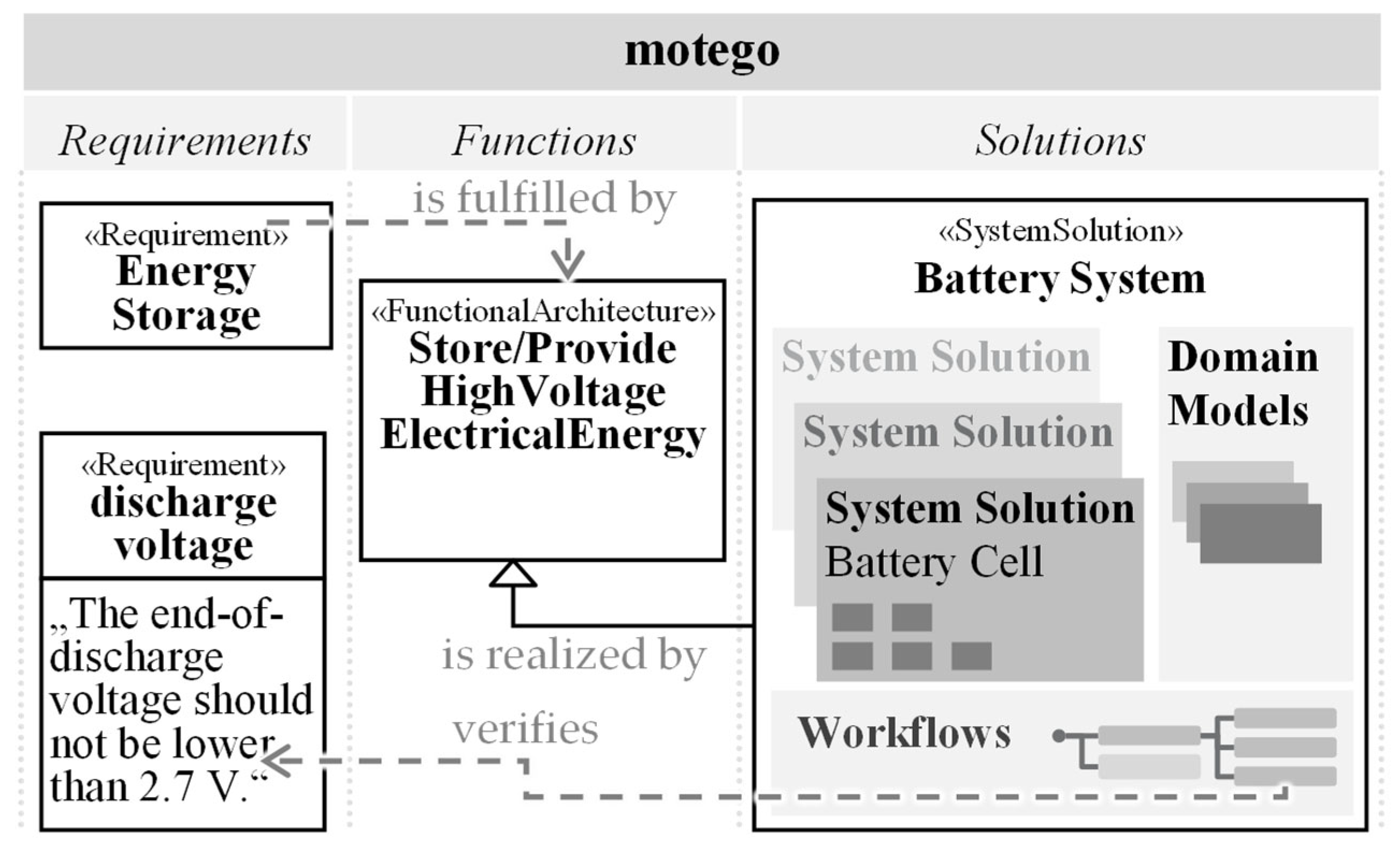
In the motego method, based on the requirements, functions are derived, which, in turn, are realized by solutions. The solutions specify the realization of the functions through the physical effect and the description of the active surface set and materials. Requirements, functions and solutions are seamlessly interconnected in the system architecture, reaching from
SolutionElements at the contact level to
SystemSolutions at the sub- or overall system level. In this paper, we focus on the system level and demonstrate our approach by using a
SystemSolution to model a whole battery system as a running example (see
Figure 1). However, the approach can be applied to
SolutionElements as well and is applicable to system models for all kinds of products and systems.
The SystemSolution contains a parametric description of the solution concept with interconnected simulation models in the domains of engineering, production and controlling to test and design solutions with respect to the requirements. To enable a simple mechanism for testing and design, so-called workflows are modeled and saved in the SystemSolution that combine domain models.
2.2. Model Classification
To test a battery system for first- and second-life scenarios with workflows, there are two key challenges: first, the most appropriate models must be selected for a given problem, and second, the input and output parameters of the selected models must be correctly interconnected. Both challenges must also be addressed again if information in the system model or one individual domain model changes. In particular, when considering multiple life cycles, changes in requirements frequently arise because the initial prediction of the battery condition (state of health) may differ from the real usage.
For the development of battery systems, there is a large, grown model landscape, which is characterized by models of different purposes and fidelities as well as by partly or hardly recognizable, but important, differences in the parameter inputs and outputs. These models are typically not documented uniformly, and the mentioned properties are not usually directly machine-processable. Therefore, often, only experts with deep insight into the models can select them in the best possible way and interconnect them correctly. As a result, both models and workflows for the designing and testing of battery systems are not efficiently reusable, and the effort of model experts increases as the number and complexity of the models grow.
In order to verify a battery system for second-life scenarios and ensure safe operation for a given load profile, electrical (“state of charge”) and thermal properties (“temperature”) in particular have to be tested using the appropriate models of the scope “battery system” [
34,
35,
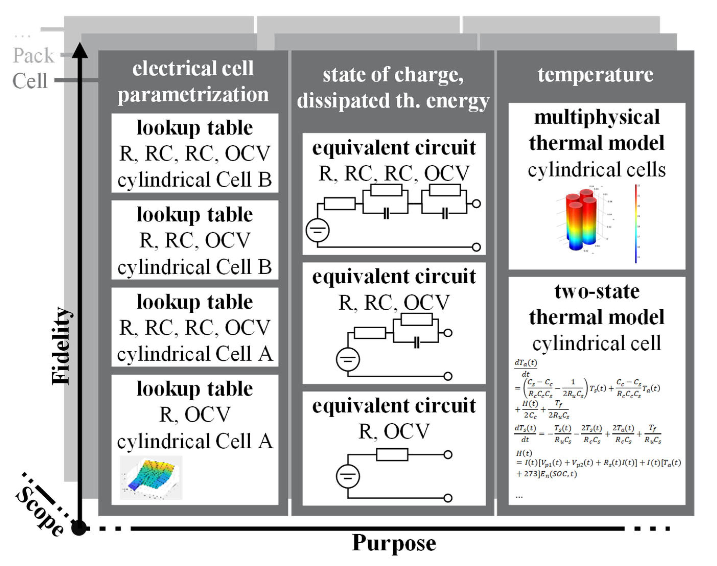
36]. Three purposes (see
Figure 2) are required to fulfill this task. There are multiple models with different fidelities for the purposes available that describe electrical and thermal properties (see
Figure 2). For demonstration purposes, only a selection from the model spectrum is considered. Further models can be found in [
37,
38], for example.
In the following, the description of the electrical properties of the cells using different equivalent circuits and their parametrization and the description of the thermal properties via two-state and multi-physics thermal models are explained in detail.
One option to model the battery’s “state of charge and dissipated thermal energy” with a given load profile is to simplify the chemical processes via equivalent circuits. The model’s fidelity level can be managed via the selection and connection of electrical components (e.g., resistance, R, and capacitance, C). The simplest model represents one battery cell via a resistor (R) and open-circuit voltage (OCV). Higher-fidelity models use, for example, equivalent circuits with one or more additional parallel RC elements.
Equivalent circuit models rely on the parametrization of the electrical components, which varies with the selected cell type and depends on the state of charge (SoC) and the temperature of the cell. These parameters are typically determined via experimental tests and formalized in lookup tables. These lookup tables specify the relationship between the temperature, the SoC and the parameter value of a single element of the equivalent circuit and are the core of the “electrical cell parametrization” purpose models.
Due to the mentioned dependencies, a description of the thermal properties of the cell is relevant, on the one hand, to determining the temperature as an input parameter for the parameterization of the equivalent circuit and, on the other hand, to verify that the battery does not exceed the maximum temperatures during operation.
Figure 2 shows two models of the purpose “temperature” for calculating cell temperatures. The two-state thermal model describes the thermal properties of a cylindrical cell based on dissipated thermal energy without considering differences in thermal conduction due to the arrangement of the cells. The multi-physical thermal model considers not only the dissipated thermal energy but also the heat exchange between the cells and can thus represent the thermal properties of the battery with higher fidelity. However, this model also requires additional input parameters, such as cell positions.
2.3. Model Signatures
To perform specific development tasks concerning the first- and second-life scenarios of battery systems with the previously classified models, a major model that calculates the target variable must be selected from the previously classified models. The major model calculates the physical quantities, which can be used to verify the requirements of interest. Typically, multiple models are required, which calculate auxiliary parameters and supply them as input to the major model. A defined set of multiple interconnected models in a system model with a defined set of parameters is referred to as a model network in the following. Since there are often several models for one purpose that can calculate the same parameters (see
Figure 2), there are numerous possible model networks that can be used to calculate the target variable and perform the development task.
To successfully execute model networks, it must be ensured that all required input parameters can be provided via an output parameter from another model or externally. To be able to interconnect two models, the supplied output and required input of the two models must exactly match. This includes the physical quantity, the physical unit, the spatial resolution (0–3-dimensional) and the temporal resolution (transient or intransient).
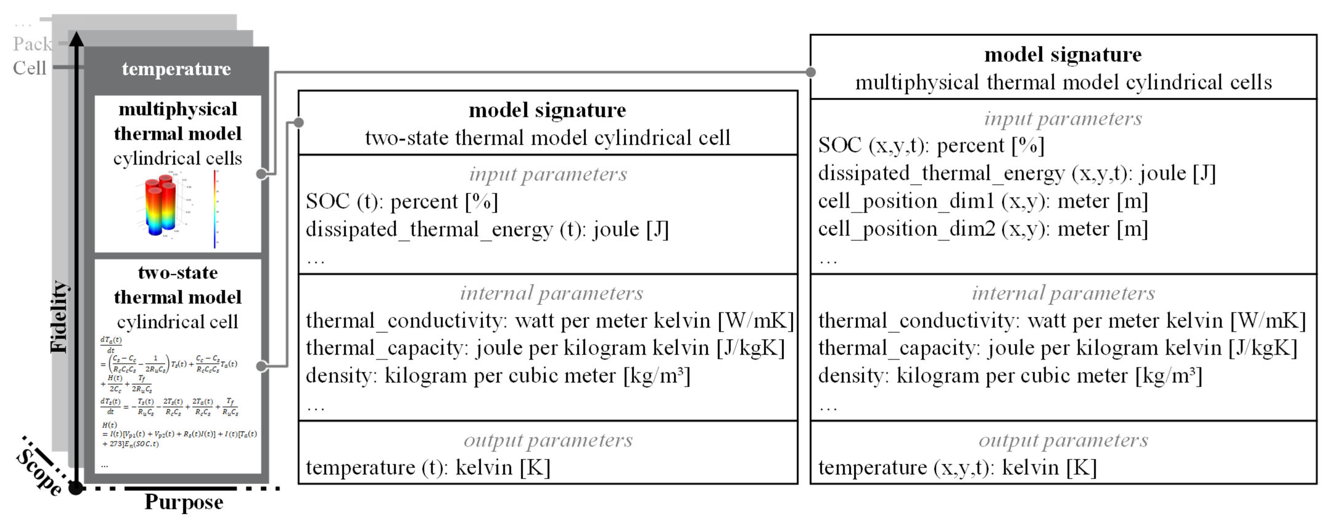
An example of the interconnection of two models via their parameters is thermal energy, which must be transferred from one of the equivalent circuit models to the model “multiphysical thermal model cylindrical cells”. Since the thermal model’s computations are spatially two-dimensional and temporally transient, this thermal energy must be resolved in spatial and temporal dimensions (x,y,t) and is measured in joules (see
Figure 3). In addition to the dissipated thermal energy, the thermal capacity and thermal conductivity must also be known among the other parameters to calculate the temperature. These two parameters are fixed values in the model and cannot be influenced externally (except for a permanent change in the default value). Nevertheless, it is very important to know about the existence and values of these parameters in order to ensure consistency with other instances of the same parameter in other models.
When combining the described consistency requirements with the combinatorial diversity within the models and model networks of a SolutionElement or SystemSolution, it becomes clear that the correct parametric interconnection is essential to obtaining valid simulation results. Since the information about model inputs and outputs, as well as the internal parameters, has not yet been documented in a standardized and machine-readable way in research and corporate practices, interconnecting models is a laborious, manual task that requires deep expertise about the respective models. In order to be able to generate valid model networks as automatically as possible, a machine-processable, formal representation of the interfaces is required, which can be evaluated to assess the compatibility of the models and their parameters.
Because of this shortcoming, the concept of model signatures was developed [
26]. The underlying idea of model signatures is a standardized, formalized and automatically evaluable documentation of all the input, output and internal parameters of a simulation model. The input parameters are entered into the model as a prerequisite for the calculation, the internal parameters are unaffected in the model and the calculation result is returned as one or multiple output parameters. For each parameter, in addition to the physical quantity, its unit, temporal and spatial resolution is specified.
Figure 3 shows the model signatures of the two models using the temperature purpose as an example. Here, it can be seen from the model signature that both models return the temperature in the same unit, but in one case, it is as a scalar, and in the other case, it is as a two-dimensional matrix with the individual temperatures of several cells. Accordingly, the spatially resolved model also requires additional parameters for the geometric position of the battery cells, which are listed as input parameters in the model signature.
2.4. Integration of Domain Models into the System Model Based on Model Classification and Model Signatures
A major problem in the integration of multiple domain models for each purpose into the
SolutionElements and
SystemSolutions is the complexity that arises from the necessary interconnections. In [
25], a SysML model structure is presented that clearly defines how domain models can be integrated into
SolutionElements so that the interconnection is well structured and it is easy to switch between models of the same purpose.
In the following, the integration of domain models according to [
25] is transferred to a
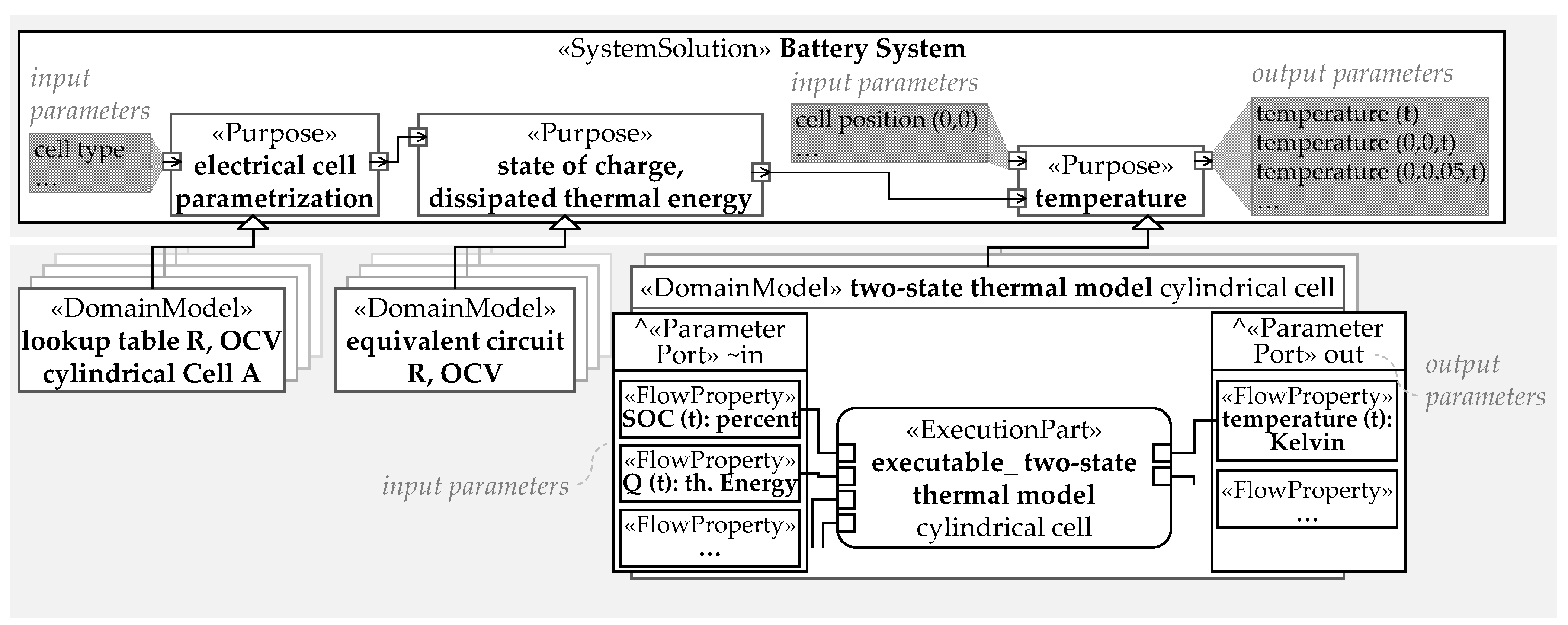
SystemSolution for the running example. In this approach, domain models are connected to a purpose block via a generalization relationship. The purpose acts as an empty container into which any domain model assigned to the purpose can be inserted. The parameter exchange between the models is performed by interconnecting the purpose via standardized ports (see
Figure 4). The ports contain a union of all input and output parameters of the domain models for one purpose, which can be generated from their respective model signatures. Each model assigned to the purpose inherits the ports and, therefore, all the input and output parameters from that purpose.
One major advantage of this approach is that different models can be inserted into a purpose without affecting the parameter exchange and model consistency of the overall
SystemSolution, as demonstrated in [
25]. In addition, the approach enables the simple “modular” implementation of new models and purposes. Thus, it is possible to build a single, reusable
SystemSolution for all available models.
Applying the approach to system models for battery systems leads to the
SystemSolution, as shown in
Figure 4. The purposes “electrical cell parametrization”, “state of charge and dissipated thermal energy”, and “temperature” are directly integrated into the
SystemSolution battery system. Via generalization, the domain models described in
Figure 2 are connected to the purposes. The necessary parameter inputs for the models and the outputs generated by the models differ for each model. In
Figure 4, the inputs and outputs for the two-state thermal model cylindrical cell from the purpose “temperature” are shown according to its model signature (see
Figure 3).
This domain model needs the input parameters SOC and Q from the standardized port, which connects the model to the domain models of the state of charge and dissipated thermal energy purpose. The output of the domain model is, among other things, the temperature required for testing the operational safety for a given load cycle in the running example. The modeling technique shown in the example of a SystemSolution is applicable to SolutionElements just like the model classification and model signature.
3. Research Need
Currently, valid model networks in system models (i.e.,
SystemSolutions or
SolutionElements) have to be identified manually as well as maintained manually in the case of changes in the product development process, the system model or the domain models. This manual work is time-consuming; error-prone; can only be performed by model experts; and must be repeated when changes regarding specifications, parameters or model signatures occur [
14,
15,
16,
23,
24]. In order to reduce manual effort, an approach to automating identification and maintenance is needed. Existing approaches to identifying and building valid model networks are based on specific commercial software (e.g., Matlab, Amesim, etc.) or limited to certain domains and their models [
20,
21]. To the best of the authors’ knowledge, there is yet no general approach to automatically identifying executable model networks based on multi-domain SysML system models.
To solve the mentioned deficits, an algorithm is required to analyze and automatically identify the valid model networks in the SystemSolutions or SolutionElements depending on the model signatures. Once clear descriptions of the model signatures, as well as the relationships between the domain models, are available, the verification of valid model chains is straightforward. The main challenges are to build SysML system models and domain models in such a way that model relationships and their signatures can be extracted automatically and to develop criteria for deciding when a model network is valid for a specific development task.
Therefore, this paper addresses the following research questions:
How can valid model networks in system models be identified automatically based on model classification and model signatures during development?
How can the determined model networks be automatically updated when parameters or models are changed?
In the following, an approach to solving these questions is presented.
Section 4 introduces a new algorithm for the automated analysis of
SystemSolutions or
SolutionElements and the automated recommendation of valid model networks. The approach is demonstrated and discussed in
Section 5 using the running example of lithium-ion battery verification for second-life scenarios.
Section 6 summarizes and provides an outlook on possible future work.
4. Solution Approach to Determining Valid Model Networks
In order to solve the aforementioned deficits, an approach is presented in which system models built with the motego method are automatically analyzed with an algorithm. The algorithm can be applied to both SystemSolutions and SolutionElements. The result of the algorithm is the preselection of executable model networks, which are suggested to the user depending on the model signatures and currently known parameters. This approach enables the product developer to constantly identify the executable model networks for the verification of requirements.
This approach is based on the model classification (cf.
Section 2.2) and the model signatures (cf.
Section 2.3) as well as the predefined model structures for
SystemSolutions [
25], as shown in
Figure 4. The use of this model structure and the model signatures enables the methodical and automated analysis of
SystemSolutions because clear relationships between all the model components are defined, which can then be easily analyzed with an algorithm. Thus, a soft-coded and reusable model network algorithm for systematical system model analysis is developed that can be applied to all
SystemSolutions and
SolutionElements regardless of any changes concerning their purposes, domain models or model signatures.
For the approach,
SystemSolutions or
SolutionElements according to the presented model structure, with multiple purposes and domain models, are necessary as inputs for the algorithm. The prerequisite for the algorithm is that the models have been implemented according to the model signatures and interconnected in the system model by the system architect. These relationships are analyzed automatically by the model network algorithm. The individual steps of the procedure are shown schematically in
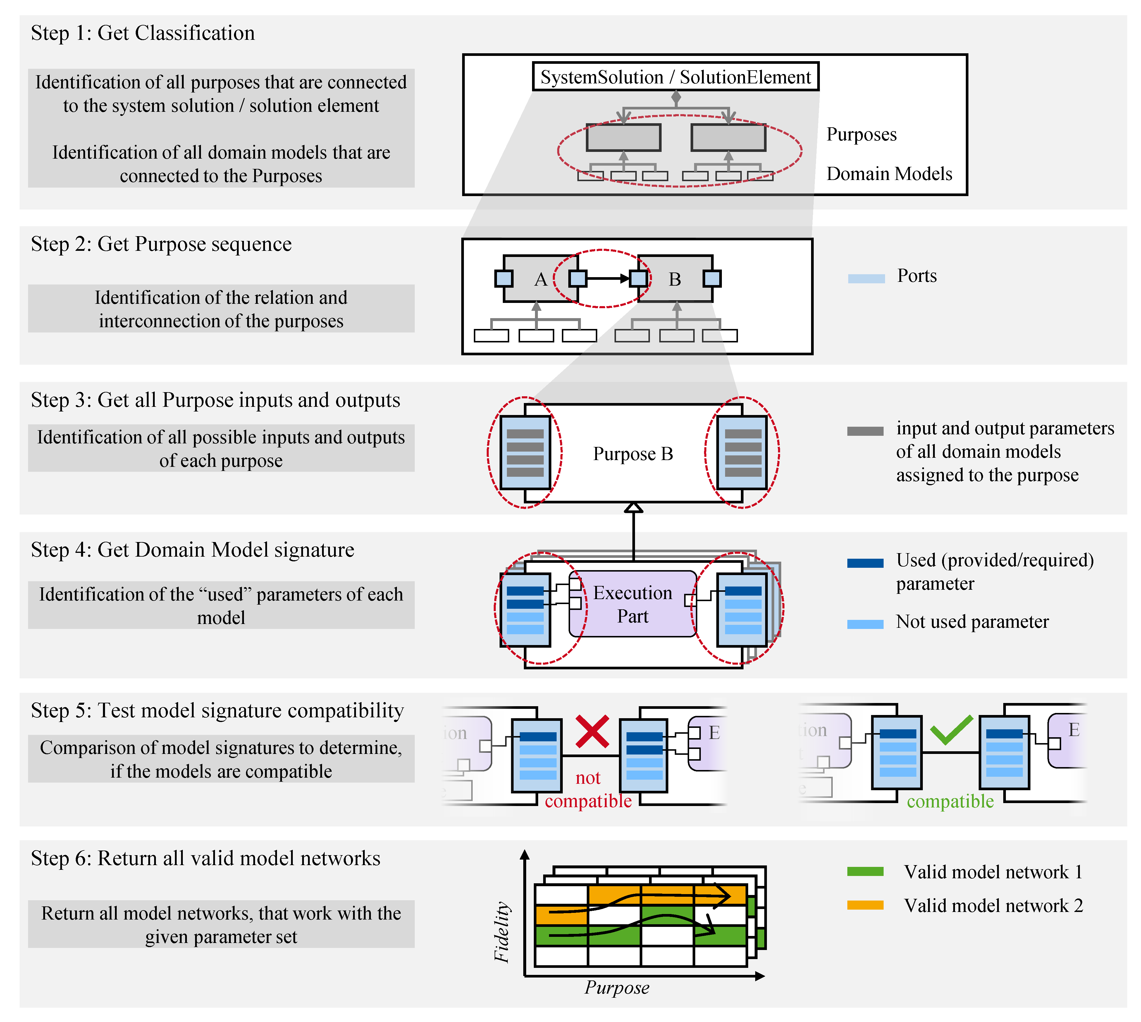
Figure 5.
First, all purposes of the
SystemSolution or SolutionElement are determined in step 1. The purposes are defined by applying the classification presented in
Section 2.2 and are connected to the
SystemSolution or
SolutionElement with a composition relationship. To do this, all parts are read from the
SystemSolution or
SolutionElement block that have the stereotype “purpose”. Then, it is determined how the purposes are related to each other to see which parameters are exchanged between the purposes (step 2). The relationship between the interconnected purposes is identified via the port connectors. Each purpose is checked to see which purpose the ports are connected to, and, thus, the purpose relationships can be easily determined.
The purposes contain the ports and, thus, the possible input and output parameters for the subordinated domain models. Therefore, for each purpose, the corresponding ports are identified. The inputs and outputs of the purposes are then determined with the flow properties that are contained in the ports (step 3). As previously described, the ports contain a union of all inputs and outputs that occur in the domain models’ signatures of each purpose, and each model inherits these input and output parameters.
Usually, the models only use a few of these input and output parameters, so they do not require all the input parameters or provide all the output parameters. As a result, the analysis of the purpose ports does not allow for a clear deduction of the model signatures and the effectively used inputs and outputs. Therefore, which inputs and outputs the domain models actually use is analyzed (step 4).
To determine the model signature from the given SystemSolution or SolutionElement, the connectors between the constraint parameters of the execution part and the flow properties of the ports are analyzed. If a constraint parameter is connected to a flow property, it is declared a used flow and is thus part of the model signature. Thus, whether it is an input or output parameter is determined by the direction of the port (conjugated or nonconjugated). A nonconjugated port indicates output parameters, and a conjugated (“reversed”) port indicates an input parameter, which is provided by another purpose.
Besides the input and output parameters, which exchange data between models, the model signature also defines the additional internal parameters that are required for the model to be able to function. These internal parameters can be, for example, the required model parameters, such as the thermal conductivity or capacity. Internal parameters are not directly provided by other models through flows. They can either be defined manually in the model itself or also be provided by an external database. In the system model, the internal parameters are not visible and, therefore, cannot be checked with the algorithm. For the integration of domain models into system models, it is, therefore, assumed that all internal parameters have been correctly defined by the corresponding model expert.
In step 5, all theoretically possible combinations are generated from all domain models of the purposes. The number of possible combinations, N
T, can be calculated using the product of the number of models per purpose, N
M:
This equation demonstrates that the manual validation of all model combinations might be very time-consuming and the length of this process increases with each additional domain model and purpose.
For all possible model combinations, whether the model signatures are compatible is then checked. First, the provided output parameters are compared with the required input parameters of the next model. If, for example, a model is not provided with all the necessary information by another model, this model combination is not valid.
Finally, the valid model networks are returned to the user and are displayed in the properties of the
SystemSolution or
SolutionElement (step 6,
Figure 5). Thus, the product developer is provided with valid model networks that can be executed with the currently given parameter set, from which he can select and, therefore, validate the product properties. When the purposes, domain models or model signatures are changed, the list of valid model networks is updated automatically.
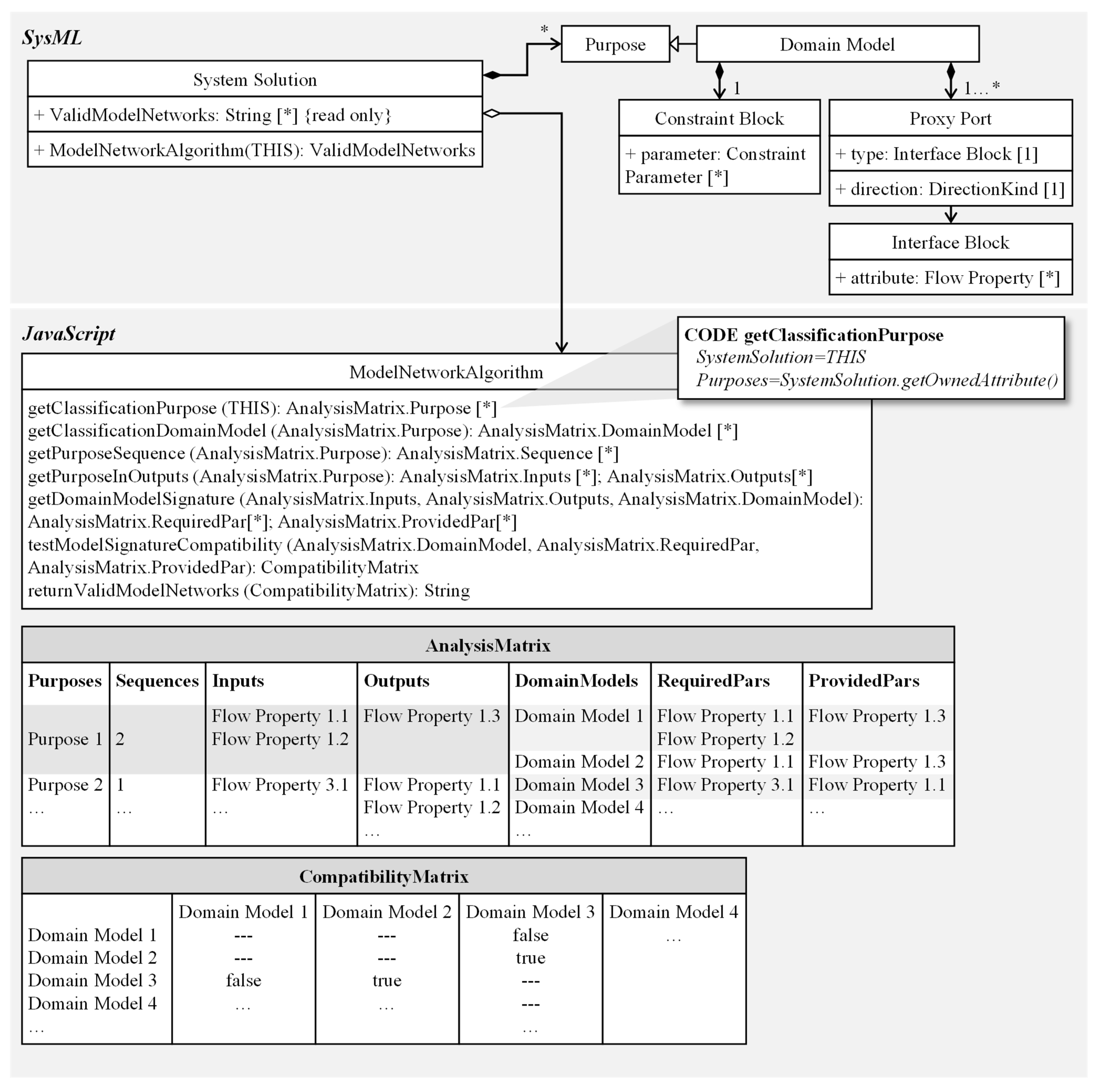
Figure 6 shows the methods implemented for each of the described steps of the algorithm in a class diagram, as well as the analyzed SysML classes. The
SystemSolution class is based on the SysML class block and is extended with the attribute
ValidModelNetworks and the method
ModelNetworkAlgorithm. The
ModelNetworkAlgorithm analyzes the elements implemented in SysML and returns a string value with a list of executable model networks in the
ValidModelNetwork property. The algorithm consists of seven sub-methods that represent each described process step in the algorithm (see
Figure 5). The figure shows the implementation of the first action of step 1 of the algorithm in detail with the corresponding JavaScript code. The input for this action is THIS, i.e., the
SystemSolution implemented in SysML. The composed purposes are determined for this
SystemSolution using get commands and returned as part of the
AnalysisMatrix. The subsequent steps are carried out in a similar way, and the analysis matrix is subsequently filled out. In the last step, we test which models are compatible with each other to form valid model networks. This test is performed by comparing the provided and required
FlowProperties of the
DomainModels. The results are listed in the compatibility matrix, which contains the different combinations of
DomainModels and their compatibility (true or false). As a final result, the valid model networks are converted into a readable string and returned to the SystemSolution’s
ValidModelNetwork attribute.
To ensure that the developed algorithm can be used in every SystemSolution and SolutionElement without repetitive implementation effort, this approach anchors the implementation with the so-called profile mechanisms of the UML. Profiles extend the SysML modeling language with method-specific notation and syntax.
Within the profile, stereotypes can be used to extend the SysML language notation and adapt it to method-specific wording. The attributes and syntax of the notation are additionally defined in the profile by so-called customizations. Customizations contain predefined attribute types, such as the derived property specification, which is taken advantage of here. Derived property specifications describe properties of the stereotype that can be derived from the relationships between existing model elements. A simple example of a derived property would be the collection of all elements that are connected to the SystemSolution with a generalization (derived property base classifier). The actual definition of the relationships that should be analyzed is achieved using so-called expressions. Expressions can be built with different tools, such as scripts or meta-chains. Meta-chains can be used to make predefined queries to model elements and their relationships. However, the capabilities of meta-chains are limited. Therefore, expressions can be implemented via scripts in various programming languages. The attributes implemented in the customizations are displayed to the system developer during modeling in the specification window of each element created with the assigned stereotype.
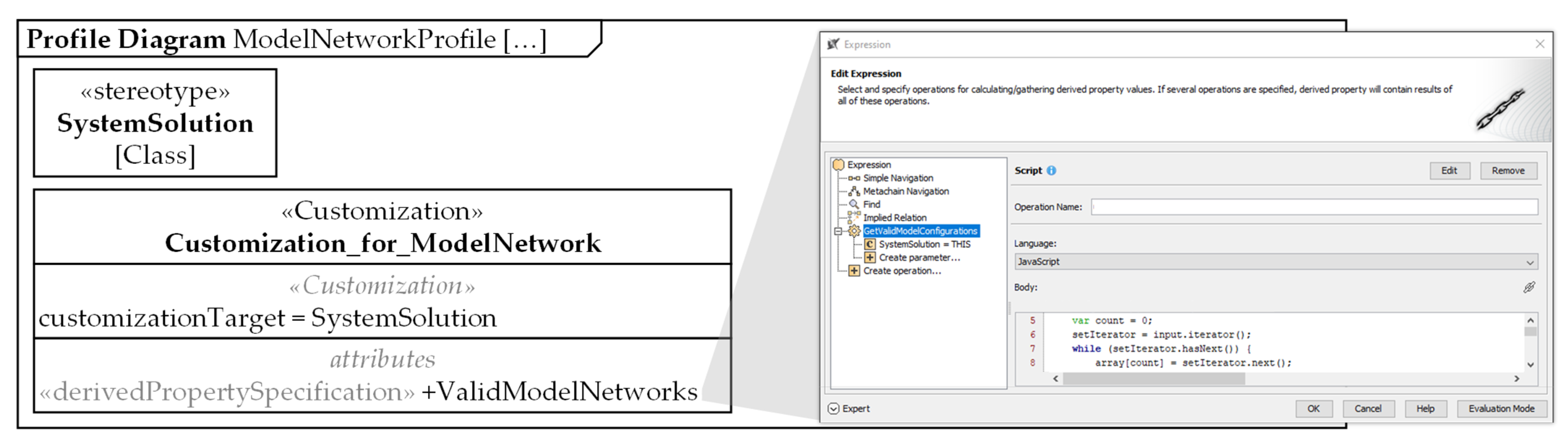
Figure 7 shows the implementation of the presented procedure of the model network algorithm in a profile for the Cameo Systems Modeler 19.0 (CSM) modeling environment [
32]. The model network profile consists of a
SystemSolution stereotype and the associated customization “Customization_for_ModelNetwork”. In the customization, an expression of the derived property “ValidModelNetworks” implements the procedure of the model chain algorithm, as shown in
Figure 5. For the implementation, the programming language JavaScript is used in combination with predefined analysis mechanisms of the CSM (see contextual variable THIS). This form of programming is chosen because the results of the algorithm are provided directly back into the specification window without any manual or additional programming efforts during the development of the system model. This means that the algorithm automatically returns possible model chains in the “ValidModelNetworks” attribute in the specification for each element that has been implemented with the
SystemSolution stereotype and linked to simulation models using the method according to ref. [
25]. The developer only has to load the language profile into his development environment and use it. Basically, the implementation of the model network algorithm based on the flowchart shown in
Figure 5 is also conceivable in other MBSE modeling environments or in other programming languages.
5. Demonstration and Discussion of the Solution Approach Using a Battery System
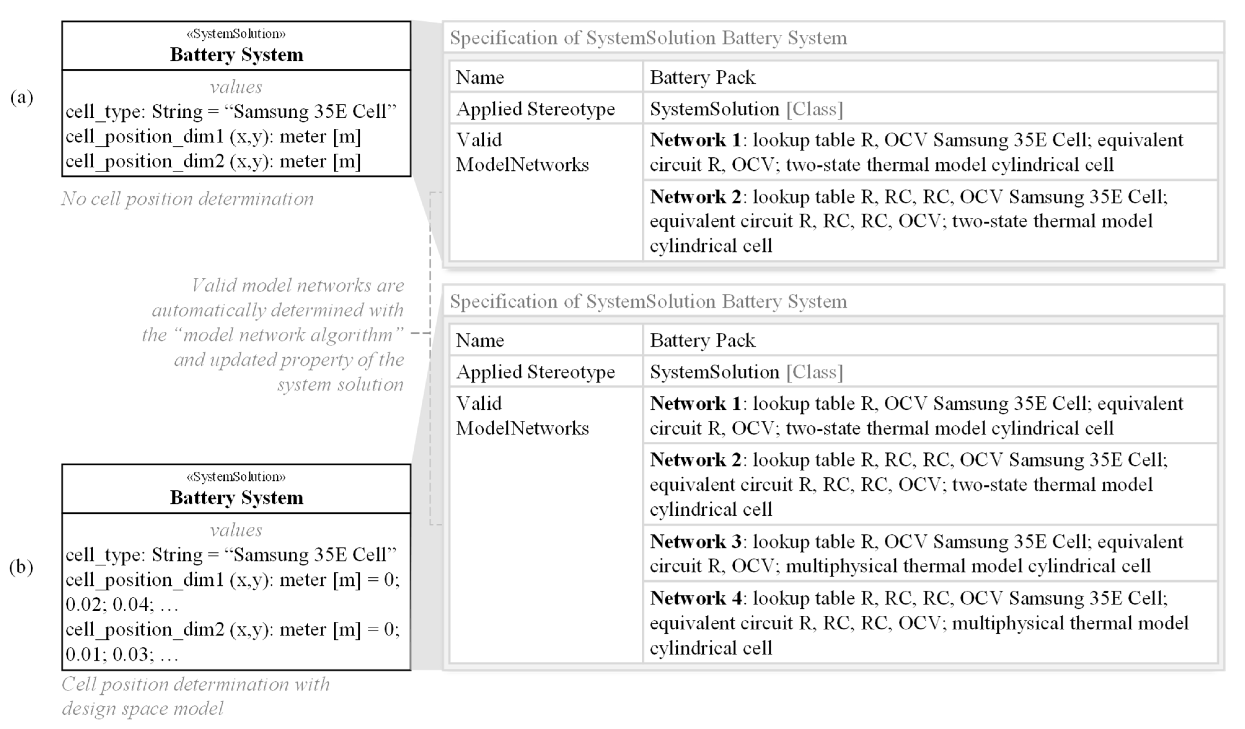
In the context of this model network, the effect of the implemented algorithm is shown using the example of two versions of a battery
SystemSolution with Samsung 35 E cells (see
Figure 8). The objective of the model network is to validate whether the Samsung 35 E cell is suitable for a given load profile. In the early stages of development, the positioning of the cells is usually not known (version a in
Figure 8). After an initial thermal simulation of single cells, the cooling system can be designed, and the positioning of the cells can be determined with the help of a design space model. This additional information in the second version of the battery system (version b in
Figure 8) results in different feasible model networks for the two
SystemSolution versions.
The executable model networks are limited, on the one hand, by the choice of the Samsung 35 E cell type. The choice of the cell type has a direct influence on the usable models of the electrical parameterization purpose, which, in turn, influences the choice of the models in the state of charge and temperature purpose. Furthermore, the available model network is limited by additional information (input parameters), such as the position of the battery cells. In order to use the temperature model with the highest fidelity (multiphysical thermal model cylindrical cell), the cell positions must be known.
For the two variants shown in
Figure 8, these restrictions result in different executable model networks, which are automatically determined by the implemented algorithm and returned in the derived property “Valid ModelNetwork”. For variant a of the battery system, only the two-state thermal model is executable for the “temperature” purpose. For the “electrical parametrization” purpose, the “lookup table R, OCV cylindrical Samsung 35 E Cell” and “lookup table R, RC, RC, OCV cylindrical Samsung 35 E Cell” models are executable. The executable models of the “electrical parametrization” purpose again predetermine that only the “equivalent circuit R, OCV” and “equivalent circuit R, RC, RC, OCV” models are executable. For variant b of the battery system, additionally, the temperature model “multiphysical thermal model cylindrical cell” is executable. This results in two more feasible model networks (see model networks 3 and 4 in
Figure 8). The two additional model networks are automatically added to the “Valid ModelNetwork” property in the specification as the cell positions are added to the
SystemSolution.
In the course of product development, system models are often modified or extended. For example, new
DomainModels can be added or new relationships between the models and system elements can be introduced. The presented approach handles changes in the system model by updating the
SystemSolution, which triggers the re-execution of the implemented algorithm and automatically performs the operations again. Within the specification of the
SystemSolution, the inputs of the model chain are determined by the underlying algorithm and the executable model networks are automatically returned in the derived property “ValidModelNetworks”. Whenever the inputs or other values change (cf. battery system version b), the information in the property “ValidModelNetworks” in the specification is automatically updated. For the user, the model networks are then updated as shown in
Figure 8 on the right by overwriting the previous information.
The identified model networks can now be implemented in the SystemSolution. To do this, the appropriate model is selected in the simulation for each purpose. The connections between the parameters are already provided by the model structure, so no further actions are necessary for the model to be executable. When multiple possible model networks are returned, the engineer must decide which model network is the most appropriate for his specific task. Possible decision criteria are, for example, the fidelity of the models and the expected runtime.
The automated calculation of valid model networks is fast even for complex system models and a high number of domain models because only the relationships between the models are compared. The models themselves never have to be executed. Without the presented approach, the engineer would have to test the executability of each model with all its parameters individually and then check the entire combinatorics of 4*3*2 = 24 model combinations each time parameters or models are changed. In large system models, the number of purposes and models can easily become very large. The manual processing of this task is then no longer feasible.
Therefore, the demonstration of the approach shows a high potential to supply the engineer with relevant development information continuously during development when a system model is used. Hence, the approach supports the model-based validation of the first- and second-life scenarios and, consequently, the continuing operation of batteries in order to further reduce their environmental impact.
6. Conclusions and Outlook
In order to enable the verification of first- and second-life scenarios for lithium-ion battery systems, it is essential to continuously know which models and model networks can be executed with the given set of parameters in different development phases. Currently, these valid model networks have to be identified manually in a time-consuming manner in system models.
Therefore, the goal of the presented approach is the automated identification of valid model networks in system models depending on the given input and internal parameter set. To achieve this goal, an algorithm is developed that automatically analyzes the given model structure of a SystemSolution. The algorithm is based on the utilization of an MBSE system model according to the “motego” modeling method. The model structure of the motego method enables the systematic analysis of the relationships between the models since models are integrated in a structured way according to the model classification. Furthermore, the input and output parameters of each model (i.e., model signatures) are clearly defined. Thus, the compatibility of the models can be checked unambiguously and automatically.
The model network algorithm is implemented using the profile mechanisms of the UML. The algorithm can thus be applied to any kind of SystemSolution and SolutionElement with any purpose, classified model or model signature. Thus, purposes as well as models, or even their model signatures, can be deleted, added or modified without affecting the functionality of the algorithm.
As a result, valid model networks are constantly updated and recommended to the product developer during the product development even when parameters change. The approach is demonstrated using the development models of second-life scenarios for lithium-ion battery systems. By using the approach, the valid model networks could be easily determined, thus constantly providing important information to the developer. The approach shows a high potential to enhance the efficiency for the verification of first- and second-life scenarios for battery systems using system models.
In future work, the identified valid model networks can be integrated into the system model in reusable workflows, as shown in [
13]. In those workflows, the selection of the desired model network can be performed automatically, e.g., in activity diagrams. The resulting predefined workflows can then be executed with just the push of a button. The desired parameters (e.g., state of charge during the lifecycle) can be calculated quickly. On the one hand, this offers the potential to easily perform data analyses (e.g., sensitivity analyses). In addition, the workflows can be extended and optimization algorithms can be applied with little effort.
During the development of the presented algorithm, several challenges were identified that need to be solved for broader applications and that shall be addressed in future research. Currently, only linear chains of purposes have been considered, as presented in the demonstration example. This means that a purpose is always connected to exactly one purpose. In the future, the algorithm will be extended for more complex chains of purposes. The compatibility of models depends not only on the temporal and spatial resolution of parameters but also on their ranges of validity. The previous approach to model signatures could be extended by this aspect.
To simplify the decision-making process when there are several possible model networks, additional decision criteria must be implemented. Using a mathematical rule with, for example, fidelity and execution time, engineers can be given additional assistance on how to choose the best model network.
In this paper, the approach was shown using a small-scale demonstration example. In the future, we plan to apply it to larger system models to further highlight the benefits of the approach. In this context, the management of model parameters and their connections will presumably be a central challenge. This requires an integrated database that efficiently supports model networks in product development. Another major challenge is deriving workflows that can optimally execute the model networks determined here in serial, parallel or iterative structures.
With these challenges in mind, the contribution presented here can be seen as the first step from classified model landscapes to partially automated, model-based systems engineering with continuously optimized model networks and workflows.


 ,
, 


