Article

Model Signatures for the Integration of Simulation Models into System Models

1
Institute for Machine Elements and Systems Engineering, RWTH Aachen University, Eilfschornsteinstr. 18, 52062 Aachen, Germany
2
Chair of Methods for Model-Based Development in Computational Engineering, RWTH Aachen University, Eilfschornsteinstr. 18, 52062 Aachen, Germany
3
Product and Systems Engineering Group, Technische Universität Ilmenau, Max-Planck-Ring 12, 98693 Ilmenau, Germany
4
Chair of Digital Engineering, Ruhr-University Bochum, Universitaetsstr. 150, 44801 Bochum, Germany
5
Chair of Software Engineering, RWTH Aachen University, Ahornstraße 55, 52074 Aachen, Germany
6
Institute of Mechatronic Design and Production, Johannes Kepler Universität Linz, Altenberger Straße 69, 4040 Linz, Austria
*
Author to whom correspondence should be addressed.
Systems 2022, 10(6), 199; https://doi.org/10.3390/systems10060199
Submission received: 15 September 2022 / Revised: 20 October 2022 / Accepted: 27 October 2022 / Published: 29 October 2022
(This article belongs to the Section Systems Engineering)

Abstract

:
Model-based systems engineering (MBSE) is an auspicious approach to the virtual development of cyber-physical systems. The behavior of the system’s elements is thus represented by specialized simulation models that are integrated into the descriptive SysML-based system model. Although many simulation models have been developed in research for the common system elements for various purposes and fidelities, their integration remains a major challenge: the parameter interfaces of the simulation models must be coupled with each other and with the parameters of the system elements in such a way that they are correctly parameterized. So far, this coupling can only be carried out by model experts in a time-consuming and error-prone manner. Therefore, in this paper, we first propose a concept that structures the system element parameters for targeted use in validation and design cases. Second, we propose a model signature for simulation models that differentiates its parameters by input, internal, output, and model parameters and specifies them with spatial and temporal dimensions as well as admissible ranges, among others. Based on the two contributions, domain models can be validly and automatable coupled and used for the virtual development of system elements in model-based systems engineering.

1. Introduction

Model-based systems engineering (MBSE) is a promising approach for the accelerated, virtual development of cyber physical systems (CPS) with reusable models [1]. Thereby, the system to be developed (e.g., a connected vehicle) is represented by a system model consisting of a hierarchical structure of system elements for the individual subsystems (e.g., top-down: mechatronic drive train, electric engine, bearing, cylindrical roller bearing, lubricated rolling contact) in accordance to [2]. Low-level system elements are also referred to as solution elements in [3,4]. Regardless the terminology, however, the modular and generic entities describe fundamental interrelationships, which are often reused in a wide variety of higher-level systems. Therefore, these low level system elements can be identified as enablers for accelerated virtual development of CPS [3,5].
Testing requirements and ensuring the functionality of the overall system concerning the mechanical domain, requires all system elements to be validated with regard to their behavior. To validate the behavior of a system element, different purposes (e.g., lifetime, friction losses, pressures, temperatures, lubrication conditions) have to be considered [3]. Since the behavior usually cannot be validated with a descriptive, SysML-based system model alone [6,7], a system element needs appropriate domain models to account for all the different purposes. A domain model is, by its nature, a representation of the original system that has been shortened or abstracted in terms of scale, detail and/or functionality [8] and typically a specialized simulation model that runs in an external software tool and needs to be integrated into the SysML-based system model [6,9,10,11,12,13]. One of the open challenges with such an integration is to provide a well-defined, modular and consistent interface between domain models and their system element counterparts, for instance to assure a correct parameter exchange. The term parameter is used in this paper analogously to [3] as a generic term for all quantitative attributes of the interfaces of domain models.
In the current state of research, numerous domain models for a specific purpose are published, which differ in terms of their used parameters, fidelity, model assumptions, computational effort, and other criteria. This leads to the challenge of selecting the most appropriate domain models, which in return requires that domain models must be identifiable with respect to relevant criteria in order to be able to clearly assign them to system elements [14]. To this end, suitable and efficient methods must be explored that enable the large variety of existing models to be sustainably utilized for model-based product development.
Another challenge is that many purposes of a system element are interdependent and coupled. As an example, pressure, temperature, and manufacturing accuracy result in certain lubrication conditions, which in turn affect service life. Neglecting these coupling effects via an isolated consideration of these purposes is not sufficient in the development process und would lead to significant errors in the system model [15,16]. Instead, it must be possible to couple the respective domain models in order to virtually represent and validate their feedback mechanisms. In doing so, it is crucial that the coupling of the domain models is consistent and correct for the specific validation question. Hence, this calls for novel research approaches to evaluate the compatibility of individual domain models in a systematic and potentially automated way. Methods for the latter are actively being worked on, yet proposed solutions are often restricted to specific simulation tools or data exchange standards.
While a decomposition of the system model into system elements is often used and common practice, low-level domain models are individually proposed and investigated in the literature, yet not analyzed in the context of a system model. Domain models are hence not systematically structured by an appropriate taxonomy that would be accessible from system models: Up to now, it has not been possible to standardize the descriptions of the numerous and often only gradually different domain models in terms of content and form. As a result, system engineers have not yet been able to identify domain models unambiguously and efficiently, assign them to associated system elements, and reuse them. Instead, system elements are usually modeled individually, often with considerable effort and expert knowledge, although they and their domain models are actually fundamentally known [14]. Since there are no standardized concepts or methods either for the parameter interfaces of the domain models or for the parameters of the system element, a great deal of effort is involved, especially in linking these parameters.
Furthermore, due to the poor documentation described above, it is not possible to clearly and efficiently evaluate if two domain models can be coupled in an automated way. As a result, system engineers either need a lot of time to reliably assess the compatibility or domain models are partially coupled incorrectly. Depending on when these errors become apparent, this leads to change costs in the development phase or, in the worst case, high recall costs in the use phase of the system.
Imagining an ideal development process, each system element and domain model would have an unambiguous and machine-readable interface description of its relevant model parameters, so that within the required time, cost and quality for the development of CPS
  • A clear and automated assignment of domain models to system elements is possible;
  • The compatibility of domain models can be automatically evaluated;
  • The most appropriate combination of domain models given a certain requirements-driven goal can be identified.
To reach this goal, we propose a parameter concept for system elements (cf. Section 4) as well as an unambiguous and machine-readable model signature for domain models (cf. Section 5). Finally, we discuss to what extent the parameter concept and model signatures help in combination to uniquely identify and correctly link domain models for system elements (cf. Section 6). For exemplary application and explanation of the results, in this paper we use the lubricated rolling contact as a typical machine element in mechanics: Two convex or convex/concave cylinder surfaces touch each other in a lubricated state at a narrow contact area where a thin lubricant film transfers mechanical forces from one surface to the other (Figure 1) [17].

2. State of the Art

Nowadays, and in the future, increasingly, CPS are being developed. CPS are characterized by interacting subsystems of the mechanical, electrical and software domain. The different subsystems and development processes of the domains lead to an immanent complexity in the development of CPS [18,19].

2.1. Function-Oriented Model-Based Systems Engineering

A promising approach to multidisciplinary CPS development is function-oriented model-based systems engineering whose key element is a cross-domain functional architecture typically modeled with the Systems Modeling Language (SysML) [7] or an advanced profile based on SysML [20]. This functional architecture is derived from the requirements and comprises functional flows as interfaces between the functions [20,21]. Based on this functional architecture, all involved domains develop system elements that realize the individual functions assigned to them. These system elements inherit the functional flows of the functions and can thus be developed modularly within the specific domains. Due to this encapsulation, the system elements have a low complexity and jointly represent the behavior of the superordinate system. As a rule, several function-oriented decomposition steps are necessary to reduce the typical CPS complexity within the system elements to a manageable level. This results in a system architecture consisting of system elements across multiple hierarchy levels. The elementary system elements at the lowest level describe very small and fundamental relationships (Figure 2) [3]. One example of such a function-oriented and model-based development approach is the motego method, which has already been applied in several research projects and is continuously being extended [4,22,23,24].
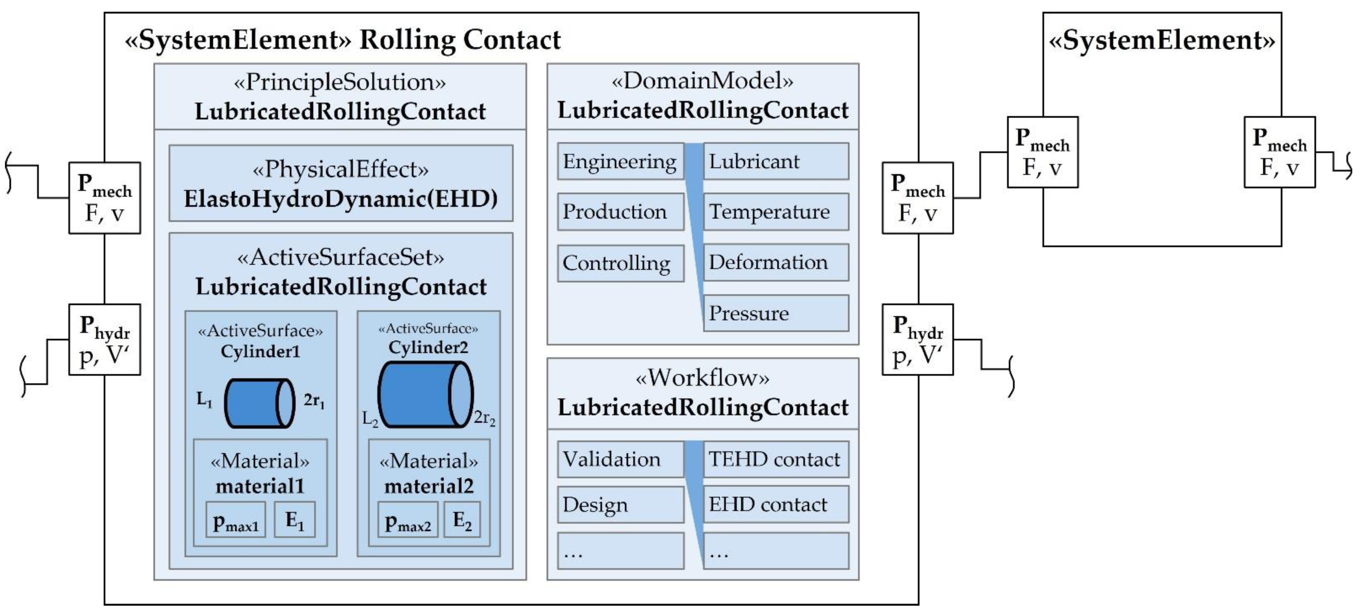
Figure 2 shows the system element lubricated rolling contact which comprises three main constituents: The principle solution, domain models and workflows [3].
The principle solution is an established concept in design methodology to describe solutions based on physical effects and active surfaces with certain geometric and material properties [21,25,26,27]. The physical effect is modeled as a constraint and typically establishes a mathematical relationship between active surfaces, material properties and functional flows. This means that the equation of the physical effect comprises, e.g., the length l, which is of course also a parameter of the two active surfaces (Figure 2). To avoid redundant or inconsistent parameters, these parameters must be linked. Even if system elements sometimes describe only a small scope of a technical system, the parametric description of the active surfaces including material properties, the physical effect, the incoming and outgoing functional flows as well as other relevant physical quantities quickly result in a large number of parameters, most of which must be linked together. When domain models are integrated into the system element, the number of parameters (to be linked) increases again significantly. Since there is no simplifying structuring for the parameters occurring in the system element so far, the linkage is complex, effortful and error-prone [3,21].
The domain model section in the system element contains and structures all models relevant for the development of the scope (e.g., Lubricated rolling contact). At the top level, a differentiation is made between engineering, production and controlling models, whereby only the engineering domain is considered in this publication which typically applicates models of analytical and numerical nature calculating the physical behavior of system elements. Here, the models are classified according to their computational purpose, such as the deformation of the active surfaces or the temperature in the lubricated rolling contact [3,4,14].
Workflows are the third area in the system element. Since domain models must be coupled for specific issues in the development process [14,24,28,29], these coupled models are also stored in a reusable manner and differentiated between validation, design and optimization workflows [3].
The joint storage of principle solution, domain models and workflows enables the specification of the system element (principle solution) to be reusable and consistently linked to the behavior description (domain models) and efficiently applicable in the development (workflows) [3].

2.2. Integration and Coupling of Simulation Models

The system model with the central functional structure and the system elements provides a descriptive representation of the system under development. In order to validate system elements against requirements or to design them with respect to requirements during development, domain models that describe the behavior of the system element need to be integrated and correctly linked to parameters of the other constituents of the system element [30].
Furthermore, typically not only one but several domain models of different purposes and suitable fidelities are necessary to test and design system elements during development. This results in the fact that several domain models must be coupled with each other [3,15,30]. In order for the coupled domain models to perform valid calculations, it is essential that the domain models themselves and their parameter interfaces must be compatible with each other.
Research on the design and of mechanical system elements has built up a large number of models over the last decades. Even within a certain scope (e.g., lubricated rolling contact) and purpose (e.g., lubrication), a large number of domain models of different fidelities can be found, resulting from different (empirical) approaches, boundary conditions and simplifications [31,32]. As a result, a high two- or even three-digit number of domain models is typically available for common system elements such as bearings, gears, shaft-hub connections, or fasteners, respectively. If several domain models have to be coupled with each other, e.g., for service life calculations and wear predictions, a simple combinatoric consideration results in a very large number of potential model configurations. The naive number of model combinations can be significantly reduced, when focusing on the model configurations that are physically compatible. To avoid manual efforts and to use the potential of existing domain models, an unambiguous and machine-processable description of the models and their parameter interfaces is necessary.
For this reason, several approaches for the interaction of system model and domain models have been developed in the past. A good overview of the basic strategies for data exchange between models in general is provided by [33] and with a focus on the parameter exchange between SysML-based system models and domain models by [9,34,35]. In some approaches, SysML profiles were developed to enable data exchange, e.g., for the model transformation between system models and Modelica-based simulation models [36] or for the automatic generation of analysis models from system models [10]. In this context, [9] states that the developed interfaces are often limited to specific simulation tools and compatibility issues frequently arise due to different versions of exchange standards (e.g., FMI [37,38]). Another approach is to orchestrate the data exchange between domain models and the system model by SysML diagrams [30,39].
Often, the approaches develop a specific interface and do not address the fundamental question of how the parametric interfaces of a domain model must be formalized generally in order to enable the valid coupling of domain models inside system elements.
Therefore, it makes sense to analyze the parameter and model definitions of data exchange standards such as Functional Mock-up Interface (FMI) [37], which among other things aim to integrate Modelica domain models into SysML-based system models [40]. The FMI standard requires in particular that each functional mock-up unit contains an XML file describing the model. In addition to their name and description, the parameters of the model are characterized by their causality and variability.
The causality specifies whether the parameter is an input or output parameter, a parameter that controls the model, or a calculated, independent or local parameter. The variability defines whether a parameter is constant, fixed after the initialization, tunable or discrete. Thereby, the FMI standard allows only certain combinations of the attributes ‘causality’ and ‘variability’. In addition, it is possible to specify start, nominal, minimum and maximum values for the different types of parameters [37]. Since the FMI standard is relatively advanced, the model signature developed in this contribution should ensure its logical compatibility to FMIs.
In addition to FMI as a cross-tool standard, there is also research on model classification or signatures for specific tools. [41] aims to improve the quality of Modelica models by adding information on traceability, uncertainty and calibration in a standardized way; [42] proposes a signature for Simulink subsystems as a generalization of the interface including input and output ports as well as data stores. [43] introduces a model identity card capturing classifiers of input and output parameters as well as the expectable quality. Preliminary work on validity and credibility exists in a fundamental nature by [44] and with a focus on software intense embedded systems by [45], who developed a framework to assess and formalize the validity range of simulation models. Many of the approaches mentioned contain classifiers that are very specifically adapted to the needs and possibilities of certain software tools and only partially offer generally valid methods for the lack of logical systematization of domain models in the context of system elements for model-based development described in the introduction.
Another important research approach that has been established in software engineering is contract-based design algebra. Here, system components can be combined to form systems on the basis of predefined sets of rules [46], for example in order to automatically generate consistent design variants that meet requirements [47]. A modeling approach for evaluating compatibility between SysML blocks was introduced in [48]. This approach considers the conformance and direction of data types as well as the compatibility of the value ranges of two parameter interfaces but not on domain model level.

3. Research Question

In the introduction (cf. Section 1), three challenges were described. First, the parameters occurring in system elements are not classified in such a way that parameter associations cannot be efficiently identified when integrating domain models and workflows. Secondly, it is not possible to assess without expert knowledge and high effort whether an existing simulation model is suitable for the calculation of certain properties of a system element. Third, multiple simulation models can only be coupled manually and with a certain error rate, which can potentially lead to high damages and costs [16].
These challenges have not yet been overcome by the current state of research (cf. Section 2). Therefore, the research question addressed in this publication is:
How can an unambiguous parameter relationship be established between system elements and domain models for their identification and coupling?
Two subordinate questions can be derived from this research question:
  • How can the parameters in the system element be structured for testing and design with domain models?
  • How can model signatures for domain models be defined unambiguously and machine-readable?
The following two sections address the two derived questions: In Section 4 a parameter concept for system elements is proposed and in Section 5 a model signature for domain models based on requirements from the development process is elaborated. In Section 6, research findings are discussed, concluded, and an outlook on necessary and possible future research directions are outlined.

4. System Element Parameter Concept

As described in Section 2.1, system elements which are typically used in function-oriented model-based development consist of inherited function ports, physical effects, active surfaces with material properties, domain models, and other physical parameters. All these constituents of the system element are formalized with parameters [3,21] resulting in a large number of parameters, which can complicate the integration of domain models with their parameter interfaces. Therefore, we propose the differentiation of the following three types of parameters:
Functional flow parameters are all parameters comprised in the functional flows entering and leaving the system element. These parameters are imposed on the system element by the environment or functionally dependent system elements and reflect operating and environmental conditions. Examples include the pressure of a fluid flow and the rotational speed of a mechanical energy flow.
Design parameters can be set directly by the engineer, written into the engineering drawing, and imposed on the real product via manufacturing. These parameters may also change over time due to operation (e.g., wear) or the environment (e.g., ambient temperature), but the initial value is set by the engineer and the manufacturing process. Examples might be the diameter of an active surface or the Young’s modulus of a material.
State variables cannot be set directly by the engineer. These parameters (e.g., tensile stress) adjust themselves depending on the functional flows from the environment and operation (e.g., force) as well as the design parameters (e.g., cross-sectional area) according to the laws of physics.
It is the engineer’s task to define the design parameters in such a way that the state variables are within certain value ranges in all relevant operational and environmental scenarios experienced by the system element via the functional flows.
The proposed differentiation of parameter types helps in the integration and coupling of domain models for validation and design of system elements. The validation of system elements with workflows [30] involves checking whether the behavior of the system element meets the requirements. These requirements can relate to state variables (e.g., a maximum permissible temperature) or to functional flow parameters (e.g., the minimum required torque of a drive system). In both cases the design parameters are already known or at least estimated. This means that such domain models have to be selected and coupled with each other, which take known design parameters as input and calculate the state variable or functional flow parameter to be validated as output (Figure 3, orange).
In the case of the design of a system element, it is the other way around. One or more design parameters are to be determined such that the state variables are within the ranges of validity and the functional flow parameters are generated as required by the operating case. Therefore, such domain models must be selected and coupled in a way that the desired functional flow parameters and limits of the state variables can be taken as input and the sought design parameters are calculated as output (Figure 3, green). Of course, in addition to the sought design parameter, there are also design parameters that are already fixed or at least should not be calculated in the design workflow under consideration. These subordinate design parameters may also be an input. Figure 3 only shows the flow directions of the main parameters considered in the respective workflow in a simplified way.
Thus, the parameters of the system element are meaningfully structured for validation and design. For the appropriate selection and coupling of the domain models, these still lack an unambiguous description of the parameter interfaces, which is proposed in the following section.

5. Model Signature for Domain Models

Model signatures are an approach to describe domain models and their interfaces unambiguously and in a machine-processable way, thus enabling the valid selection and combination of domain models within a system element. Since a large number of individually and inconsistently documented domain models is actively being used, our approach to tackle the research question is to consider a collection of well-known domain models for a specific example, and to derive requirements for model signatures based on their content and form (Section 5.1). From these requirements we propose an approach for model signatures (Section 5.2).

5.1. Domain Model Requirements for the Model Signature

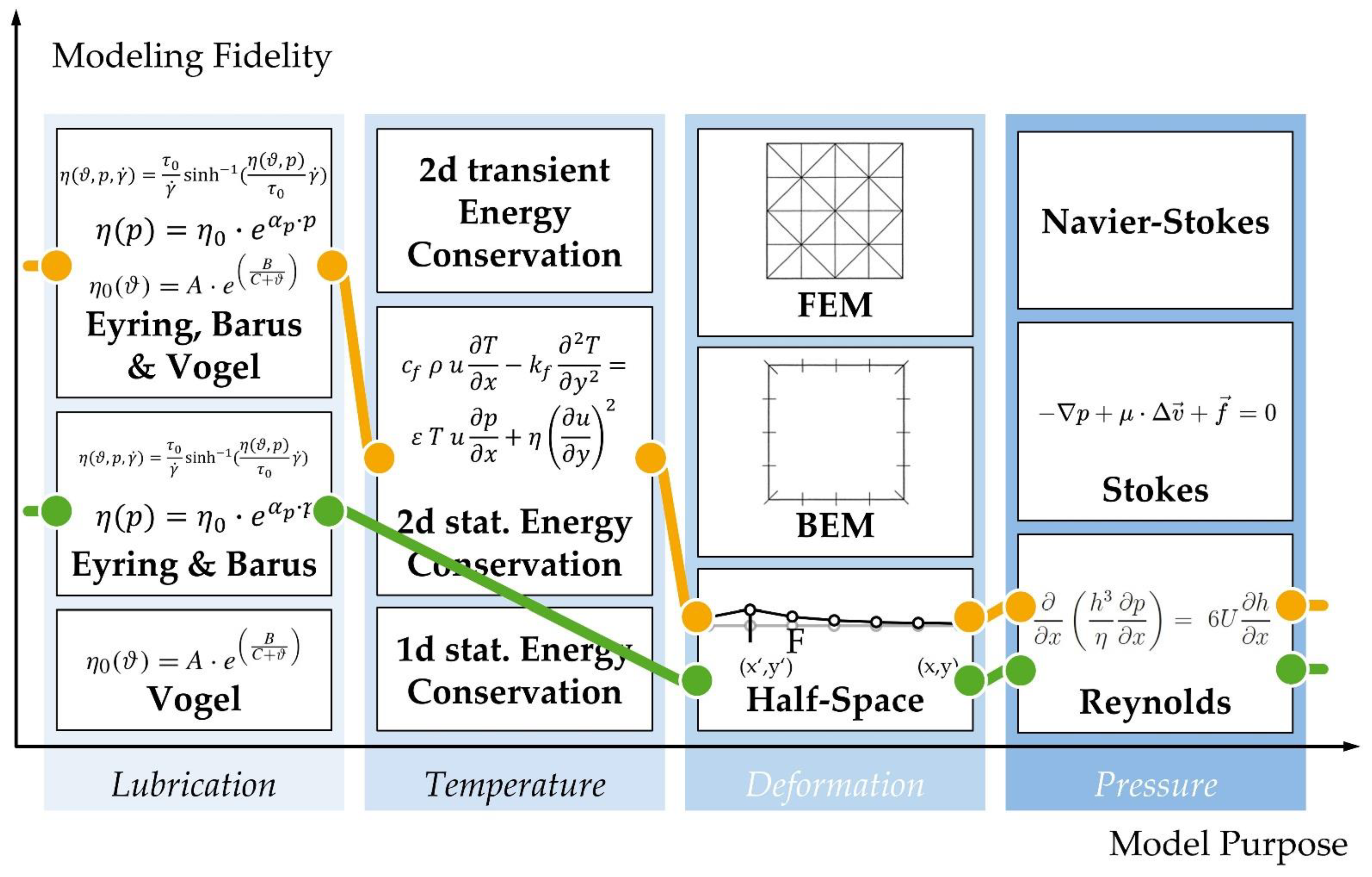
An extract of known domain models for the system element ‘lubricated rolling contact’ is shown in Figure 4. As already mentioned, they can be distinguished by purpose and fidelity [14] whereby the term fidelity is used here in the combined sense of validity and detail of [44]. In our example three domain models of various fidelity can be differentiated for the purpose ‘temperature calculation’ ranging from the assumption of a constant temperature to a fully spatially resolved, transient temperature evolution. Depending on the required modeling fidelity of (thermo-)elastohydrodynamic lubrication calculations in the lubricated rolling contact, different modeling strategies can be applied as demonstrated in Figure 4. For instance, in order to model the lubrication film, either temperature (represented by Barus equation) or pressure dependencies of the viscosity (represented by Vogel equation) in the lubrication film or the combination (represented by Eyring, Barus, and Vogel) can be considered to reach the desired fidelity levels in simulations. Analogously, different approaches for temperature, deformation and pressure calculations can be used [31,32,49]. Please note that the domain models shown are only a small excerpt. Both in the published research literature and in companies, such as a bearing manufacturer, a significantly higher number of models will be found. Based on the extent shown here, an elastohydrodynamic (EHD) calculation (Figure 4, green line) and a thermo-elastohydrodynamic (TEHD) calculation (Figure 4, yellow line) can be found as meaningful model configurations and performed as calculation.
The Assessment of the domain model compatibility requires expert knowledge or a formalized and evaluable domain model signature. Only the latter can later be utilized in automated validation tests.
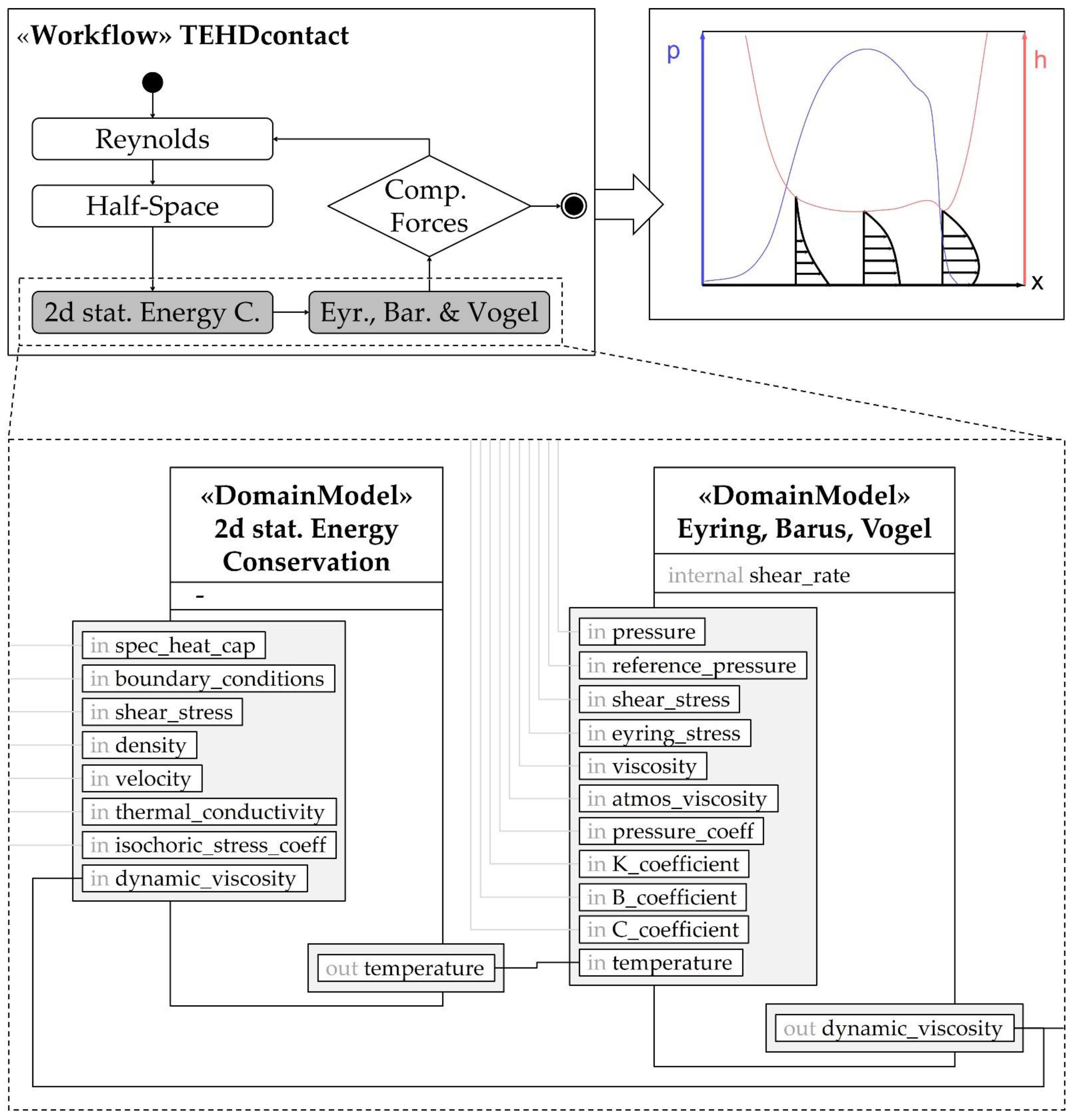
Figure 5 shows the parameters which are exchanged between the domain models if a TEHD calculation is executed. The depicted workflow (Figure 5, top left corner) combines the Reynolds equation, half-space theory, energy equation and fluid models for viscosity. After iteratively solving the equations for required parameters with given boundary conditions, the film thickness and pressure distribution in the contact area will be achieved as the result of the simulation model (Figure 5, top right corner).
Apparently, mainly state variables as well as design parameters are exchanged, which constitute input and output parameters of the domain model. Besides these input and output parameters, however, also internal parameters are needed within the individual domain models. These internal parameters only exist inside domain models, where they can be changed in the model’s code, and cannot be accessed from outside. This leads to the challenge of possible inconsistencies between invisible instances of the same internal parameter in two different domain models, which is still a common problem in system modeling. This consideration leads to the conclusion that the model signature of a domain model should not only contain input and output parameters, but also internal parameters explicitly.
Another challenge are undefined spatial and temporal resolutions of parameters. If a parameter occurs in several domain models, these instances must be linked together (e.g., the dynamic viscosity between both domain models in Figure 5) and match in particular with respect to their spatial and temporal resolutions as well as admissible physical or operational regimes. While, e.g., the spatial dimensions (x, y and z) of the parameters have to match completely, a partial match of the regimes can be sufficient to execute two coupled domain models. As a final point, it can be stated that also properties resulting from the model building must be compatible to each other. For instance, the computation times of coupled models should be harmonized in order to guarantee an efficient execution.
While input and output relations can be represented in today’s SysML the admissibility regimes require a linguistic extension of SysML. This is also the case if regime compatibility at higher hierarchical levels is to be tested with the system element parameter concept building on this contribution.
Another important aspect for the model signature is the variability of parameters. Depending on the validation and design question, the developer may want to specifically keep individual parameters constant or allow them to change. Therefore, when integrating a domain model, it must be transparent whether the model keeps the individual parameters constant or varies them partially during the calculation. Hence, the model signature for domain models should explicitly contain the variability of the parameters in addition to the classification according to input, internal and output, dimensions, regimes and execution times.

5.2. Proposal of a Model Signature for Domain Models

From the requirements identified based on domain models (cf. Section 5.1), the following proposal of a domain model signature is derived comprising four constituents (Figure 6).
Among the input parameters all parameters are collected, which are needed as input for the specific calculation purpose of the domain model. Similarly, the output parameters are also specified, which are result of the calculation purpose of the particular domain model. In addition to the input and output parameters, the internal parameters are also included as a third constituent, which are characterized by the fact that they cannot be specified or read out externally of the domain model calculation.
The domain model signature specifies all input, output and internal parameters, concerning their name, dimension, data type, physical quantity and unit, spatial and temporal resolution as well as admissible regimes (Figure 6). Additionally, it is indicated whether the parameter is fixed or tunable inside the model. For example, it is defined that the domain model ‘Eyring, Barus, Vogel’ needs an input parameter ‘pressure’ with unit ‘Pa’, which is resolved in x and y direction as well as in time. This parameter is fixed since it is not changed or optimized inside this particular domain model. This fluid model is valid for moderate temperatures [50] and low pressures [49]. To fix the admissible regimes in the proposed model signature, temperatures up to 100 °C and pressures of 100 kPa to about 1 GPa are assumed as an example. The parameter specification (Figure 6, right) is a suggested notation that allows an algorithm-based evaluation of parameter compatibilities. For example, the unit Pascal is expressed via the exponents of the power product of the seven standardized SI units [51].
As a last parameter group, the domain model signature also contains the model parameters. These model parameters have no equivalent on the modeled system, but arise from the way the model is built. These include, for example, the computation time, time steps or termination criteria.

6. Discussion, Conclusion and Outlook

In this section, we discuss and summarize the results and provide an outlook for future research.

6.1. Discussion

Besides the advantage of an unambiguous and machine-readable description, the model signature also offers the possibility to evaluate the formal compatibility of domain models. The domain models considered in this example for the system element ‘lubricated rolling contact’ can be combined theoretically to 81 different model chains (Figure 4). This example is still idealized, such that in reality many more combinations can be expected. Of course, not all of the model chains can be technical coupled. Even with in-depth knowledge of the domain models, it is not possible to reliably and reproducibly filter out incompatible model chains without error and with acceptable effort. The proposed model signatures allow to easily and unambiguously determine whether the respective coupled parameters match in terms of dimensions, data type, unit, spatial and temporal resolution, and regime.
In order to reduce the set of possible model configurations to compatible ones with the proposed model signature, it makes sense to implement the model signature as an extension of SysML in a language profile. For example, the mechanisms of structural expressions in system modeling environments such as Cameo could be used to automatically evaluate compatible domain models [52].

6.2. Conclusions

In function-oriented model-based system development, executable domain models must be integrated into the SysML-based descriptive system model in order to virtually validate and design its system elements. Since all constituents of a system element are formalized via parameters, the challenge arises on the one hand of how to structure these parameters in order to connect them in a meaningful way with the domain models. At the same time, a large number of domain models exist for typical mechanical system elements, which are not documented in a standardized manner, and therefore, on the other hand, can only be integrated into the system element and coupled with each other in a effortful and failure-prone manner. Therefore, we proposed a parameter concept for system elements and a domain model signature, which are harmonized with each other and allow the integration and unambiguous coupling of domain models inside system elements.
The parameter concept for system elements distinguishes its parameters into design parameters that need to be defined by engineers or models, state variables that cannot be set directly be engineers and adjust themselves according to the laws of physics, as well as functional flows that enter and leave the system element representing operating and environmental conditions.
The proposed notion of model signatures specifies domain models concerning the following attributes. All input, internal and output parameters are defined by their respective name and their physical quantity. Furthermore, the physical is indicated by the power of the seven standardized SI units. The admissible regime is specified by a basically unrestricted set of constraints. Thus, several disjoint ranges of validity can also be expressed by minimum and maximum values or a formulaic relationship. Furthermore, the spatial and temporal resolution as well as the variability are provided. The latter categorizes whether the value of a parameter is fixed or tunable through changes or optimizations inside the domain model. The domain model signature additionally includes the model parameters as a final parameter group. These model parameters are a result of how the model is constructed rather than having an equivalent in the modeled system.
This unambiguous and machine-processable description allows domain models to be validly coupled with each other. In combination with the parameter concept, the domain models can read and calculate parameters of the system element according to the certain validation and design cases.

6.3. Outlook

In this article, we motivated the necessity of model signatures and investigated its realization based on a specific example. The conceptual approach, however, is not restricted to system elements representing the lubricated rolling contact in a gearing box, but can be generalized to other system elements. In order to further develop and establish the concept of model signatures, it will therefore be important to apply it to additional, typical system elements in the course of further research. In this context, it makes sense to extend SysML with a possibility to specify resolutions and regimes in order to formulate model signatures with this language in the future. In preparation for application, it is also necessary to develop algorithms for automated compatibility checking and coupling of domain models.
The proposed notion of model signatures also reminds of software structures used in multi-physics software systems, that choose an object-oriented approach, in which ‘model classes’ exist that encapsulate a certain process model to facilitate hierarchical modeling [53], or reproducibility [54]. A specific simulation is then an object of class model with certain parameters (constraining the physical regime) and certain underlying mathematical and numerical methods (that define spatiotemporal resolution). Such an object-oriented software structure also helps to orchestrate high-throughput simulations such as needed for model-based uncertainty management. Additionally, ontologies could provide a way to semantically express and make usable the information needed to select and link simulation models from a model building perspective [55,56]. Combing these closely related concepts will offer new pathways towards a conceptual integration of system models with high-fidelity simulation models.

Author Contributions

Methodology, T.Z., G.J., J.K., S.H., D.G., B.R., K.Z., S.V., F.K. and G.H.; Writing—original draft, T.Z.; Writing—review and editing, T.Z., G.J., J.K., S.H., D.G., B.R., K.Z., S.V., F.K. and G.H. All authors have read and agreed to the published version of the manuscript.

Funding

This research received no external funding.

Conflicts of Interest

The authors declare no conflict of interest.

References

  1. INCOSE. Systems Engineering Vision. 2020. Available online: https://sdincose.org/wp-content/uploads/2011/12/SEVision2020_20071003_v2_03.pdf (accessed on 4 October 2022).
  2. Ropohl, G. Allgemeine Technologie: Eine Systemtheorie der Technik; KIT Scientific Publishing: Karlsruhe, Germany, 2009. [Google Scholar]
  3. Jacobs, G.; Konrad, C.; Berroth, J.; Zerwas, T.; Höpfner, G.; Spütz, K. Function-Oriented Model-Based Product Development. In Design Methodology for Future Products: Data Driven, Agile and Flexible, 1st ed.; Krause, D., Heyden, E., Eds.; Springer eBook Collection; Springer: Cham, Switzerland, 2022. [Google Scholar]
  4. Spütz, K.; Berges, J.; Jacobs, G.; Berroth, J.; Konrad, C. Classification of Simulation Models for the Model-based Design of Plastic-Metal Hybrid Joints. Procedia CIRP 2022, 109, 37–42. [Google Scholar] [CrossRef]
  5. Husung, S.; Weber, C.; Mahboob, A. Model-Based Systems Engineering: A New Way for Function-Driven Product Development. In Design Methodology for Future Products; Springer: Cham, Switzerland, 2022; pp. 221–241. [Google Scholar] [CrossRef]
  6. Chabibi, B.; Anwar, A.; Nassar, M. Towards an alignment of SysML and simulation tools. In Proceedings of the 2015 IEEE/ACS 12th International Conference of Computer Systems and Applications (AICCSA), Marrakech, Morocco, 17–20 November 2015; IEEE: Piscataway, NJ, USA, 2016; pp. 1–6. [Google Scholar]
  7. Object Management Group. OMG System Modeling Language Specification: Version 1.5. Available online: https://www.omg.org/spec/SysML/1.5 (accessed on 14 July 2022).
  8. Stachowiak, H. Allgemeine Modelltheorie; Springer: Wien, Austria, 1973. [Google Scholar]
  9. Nigischer, C.; Bougain, S.; Riegler, R.; Stanek, H.P.; Grafinger, M. Multi-domain simulation utilizing SysML: State of the art and future perspectives. Procedia CIRP 2021, 100, 319–324. [Google Scholar] [CrossRef]
  10. Kim, H.; Fried, D.; Menegay, P.; Soremekun, G.; Oster, C. Application of Integrated Modeling and Analysis to Development of Complex Systems. Procedia Comput. Sci. 2013, 16, 98–107. [Google Scholar] [CrossRef] [Green Version]
  11. Wilking, F.; Sauer, C.; Schleich, B.; Wartzack, S. Integrating Machine Learning in Digital Twins by utilizing SysML System Models. In Proceedings of the 2022 17th Annual System of Systems Engineering Conference (SOSE), Rochester, NY, USA, 7–11 June 2022; IEEE: Piscataway, NJ, USA, 2022; pp. 297–302. [Google Scholar] [CrossRef]
  12. Husung, S.; Weber, C.; Mahboob, A. Integrating Model-Based Design of Mechatronic Systems with Domain-Specific Design Approaches. Proc. Des. Soc. 2022, 2, 1895–1904. [Google Scholar] [CrossRef]
  13. Husung, S.; Gerhard, D.; Jacobs, G.; Kowalski, J.; Rumpe, B.; Zeman, K.; Zerwas, T. Model signatures for design and usage of simulation-capable model networks in MBSE. In Proceedings of the IFIP 19th International Conference on Product Lifecycle Management, Grenoble, France, 7–13 July 2022. [Google Scholar]
  14. Hoepfner, G.; Kowalski, J.; Faustmann, C.; Zerwas, T.; Kranabitl, P.; Vafaei, S.; Jacobs, G.; Hick, H. A Classification Method for the Systematic Identification of Models and Workflows in MBSE. In DS 119: Proceedings of the 33rd Symposium Design for X (DFX2022), Hamburg, Germany, 22–23 September 2022; The Design Society: Glasgow, UK, 2022; pp. 1–10. [Google Scholar] [CrossRef]
  15. Torres, W.; Brand, M.V.D.; Serebrenik, A. Model Management Tools for Models of Different Domains: A Systematic Literature Review. In Proceedings of the 13th Annual IEEE International Systems Conference, Hyatt Grand Cypress Hotel, Orlando, FL, USA, 8–11 April 2019; pp. 1–8. [Google Scholar] [CrossRef]
  16. Torres, W.; Brand, M.G.J.V.D.; Serebrenik, A. A systematic literature review of cross-domain model consistency checking by model management tools. Softw. Syst. Model. 2021, 20, 897–916. [Google Scholar] [CrossRef]
  17. Haberhauer, H.; Bodenstein, F. Maschinenelemente; Springer: Berlin/Heidelberg, Germany, 2009. [Google Scholar]
  18. Broy, M. Challenges in automotive software engineering. In Proceedings of the 28th International Conference on Software Engineering, Shanghai China, 20–28 May 2006; Osterweil, L.J., Ed.; Association for Computing Machinery: New York, NY, USA, 2006; pp. 33–42. [Google Scholar]
  19. France, R.; Rumpe, B. Model-driven Development of Complex Software: A Research Roadmap. In Proceedings of the Future of Software Engineering, Minneapolis, MN, USA, 23–25 May 2007; Briand, L.C., Ed.; IEEE: Los Alamitos, CA, USA, 2007; pp. 37–54. [Google Scholar] [CrossRef]
  20. Drave, I.; Rumpe, B.; Wortmann, A.; Berroth, J.; Hoepfner, G.; Jacobs, G.; Spuetz, K.; Zerwas, T.; Guist, C.; Kohl, J. Modeling mechanical functional architectures in SysML. In Proceedings of the 23rd ACM/IEEE International Conference on Model Driven Engineering Languages and Systems, Virtual Event, Canada, 16–23 October 2020; Syriani, E., Ed.; Association for Computing Machinery: New York, NY, USA, 2020; pp. 79–89. [Google Scholar]
  21. Zerwas, T.; Jacobs, G.; Spütz, K.; Höpfner, G.; Drave, I.; Berroth, J.; Guist, C.; Konrad, C.; Rumpe, B.; Kohl, J. Mechanical concept development using principle solution models. IOP Conf. Series: Mater. Sci. Eng. 2021, 1097, 012001. [Google Scholar] [CrossRef]
  22. Menninger, B.; Wiechel, D.; Rackow, S.; Höpfner, G.; Oleff, C.; Berroth, J.; Gräßler, I.; Jacobs, G. Modellierung und Analyse funktionaler Varianz komplexer technischer Systeme. In Proceedings of the 33nd Symposium Design for X, Hamburg, Germany, 22–23 September 2022. [Google Scholar]
  23. Börner, M.F.; Frieges, M.H.; Späth, B.; Spütz, K.; Heimes, H.H.; Sauer, D.U.; Li, W. Challenges of second-life concepts for retired electric vehicle batteries. Cell Rep. Phys. Sci. 2022, 3, 19. [Google Scholar] [CrossRef]
  24. Zhang, Y.; Roeder, J.; Jacobs, G.; Berroth, J.; Hoepfner, G. Virtual Testing Workflows Based on the Function-Oriented System Architecture in SysML: A Case Study in Wind Turbine Systems. Wind 2022, 2, 599–616. [Google Scholar] [CrossRef]
  25. Koller, R. Konstruktionslehre für den Maschinenbau. Grundlagen zur Neu- und Weiterentwicklung Technischer Produkte mit Beispielen, 4th ed.; Springer eBook Collection Computer Science and Engineering; Springer: Berlin/Heidelberg, Germany, 2013. [Google Scholar]
  26. Pahl, G.; Beitz, W.; Feldhusen, J.; Grote, K.-H. Engineering design. In A Systematic Approach, 3rd ed.; Springer: London, UK, 2007. [Google Scholar]
  27. Koller, R.; Kastrup, N. Prinziplösungen zur Konstruktion Technischer Produkte, 2., Neubearb. Aufl.; Springer: Berlin, Germany, 1998. [Google Scholar]
  28. Zhang, Y.; Hoepfner, G.; Berroth, J.; Pasch, G.; Jacobs, G. Towards Holistic System Models Including Domain-Specific Simulation Models Based on SysML. Systems 2021, 9, 76. [Google Scholar] [CrossRef]
  29. Habermehl, C.; Höpfner, G.; Berroth, J.; Neumann, S.; Jacobs, G. Optimization Workflows for Linking Model-Based Systems Engineering (MBSE) and Multidisciplinary Analysis and Optimization (MDAO). Appl. Sci. 2022, 12, 5316. [Google Scholar] [CrossRef]
  30. Höpfner, G.; Jacobs, G.; Zerwas, T.; Drave, I.; Berroth, J.; Guist, C.; Rumpe, B.; Kohl, J. Model-Based Design Workflows for Cyber-Physical Systems Applied to an Electric-Mechanical Coolant Pump. IOP Conf. Series: Mater. Sci. Eng. 2021, 1097, 012004. [Google Scholar] [CrossRef]
  31. Fischer, D.; von Goeldel, S.; Jacobs, G.; Stratmann, A.; König, F. Investigation of lubricant supply in rolling point contacts under starved conditions using CFD simulations. IOP Conf. Ser. Mater. Sci. Eng. 2021, 1097, 012007. [Google Scholar] [CrossRef]
  32. Feldermann, A.; Neumann, S.; Jacobs, G. CFD simulation of elastohydrodynamic lubrication problems with reduced order models for fluid–structure interaction. Tribol.-Mater. Surf. Interfaces 2017, 11, 30–38. [Google Scholar] [CrossRef]
  33. Paskaleva, G.; Mazak-Huemer, A.; Wimmer, M.; Bednar, T. Leveraging integration facades for model-based tool interoperability. Autom. Constr. 2021, 128, 103689. [Google Scholar] [CrossRef]
  34. Reilley, K.A.; Edwards, S.; Peak, R.; Mavris, D. Methodologies for Modeling and Simulation in Model-Based Systems Engineering Tools. In Proceedings of the AIAA SPACE 2016, Long Beach, California, 13–16 September 2016; American Institute of Aeronautics and Astronautics: Reston, VA, USA, 2016. [Google Scholar] [CrossRef]
  35. Nikolaidou, M.; Kapos, G.-D.; Tsadimas, A.; Dalakas, V.; Anagnostopoulos, D. Challenges in SysML Model Simulation. Adv. Comput. Sci. 2016, 5, 49–56. Available online: http://www.acsij.org/acsij/article/view/544 (accessed on 13 July 2022).
  36. Cao, Y.; Liu, Y.; Fan, H.; Fan, B. SysML-based uniform behavior modeling and automated mapping of design and simulation model for complex mechatronics. Comput.-Aided Des. 2013, 45, 764–776. [Google Scholar] [CrossRef]
  37. Modelica Association. Functional Mock-up Interface Specification. Available online: https://fmi-standard.org/docs/3.0/ (accessed on 12 July 2022).
  38. Blochwitz, T.; Otter, M.; Arnold, M.; Bausch, C.; Clauss, C.; Elmqvist, H.; Junghanns, A.; Mauss, J.; Monteiro, M.; Neidhold, T.; et al. The Functional Mockup Interface for Tool independent Exchange of Simulation Models. In Proceedings of the 8th International Modelica Conference, Technical Univeristy, Dresden, Germany, 20–22 March 2011; Linköping University Electronic Press: Linköping, Sweden, 2011; pp. 105–114. [Google Scholar]
  39. Kaslow, D.; Soremekun, G.; Kim, H.; Spangelo, S. Integrated model-based systems engineering (MBSE) applied to the Simulation of a CubeSat mission. In Proceedings of the 2014 IEEE Aerospace Conference, Big Sky, MT, USA, 1–8 March 2014; IEEE: Piscataway, NJ, USA, 2014; pp. 1–14. [Google Scholar] [CrossRef]
  40. Cawasji, K.A.; Baras, J.S. SysML Executable Model of an Energy-Efficient House and Trade-Off Analysis. In Proceedings of the 4th IEEE International Symposium on Systems Engineering, Rome Marriott Park Hotel, Roma, Italy, 1–3 October 2018; IEEE: Piscataway, NJ, USA, 2018. [Google Scholar]
  41. Otter, M.; Reiner, M.; Tobolář, J.; Gall, L.; Schäfer, M. Towards Modelica Models with Credibility Information. Electronics 2022, 11, 2728. [Google Scholar] [CrossRef]
  42. Bender, M.; Laurin, K.; Lawford, M.; Pantelic, V.; Korobkine, A.; Ong, J.; Mackenzie, B.; Bialy, M.; Postma, S. Signature required: Making Simulink data flow and interfaces explicit. Sci. Comput. Program. 2015, 113, 29–50. [Google Scholar] [CrossRef]
  43. Sirin, G.; Paredis, C.J.J.; Yannou, B.; Coatanea, E.; Landel, E. A Model Identity Card to Support Simulation Model Development Process in a Collaborative Multidisciplinary Design Environment. IEEE Syst. J. 2015, 9, 1151–1162. [Google Scholar] [CrossRef]
  44. Zeigler, B.P. Theory of modeling and simulation. In Discrete Event and Iterative System Computational Foundations, 3rd ed.; Academic Press: Cambridge, MA, USA, 2018. [Google Scholar]
  45. Van Acker, B.; De Meulenaere, P.; Denil, J.; Durodie, Y.; Van Bellinghen, A.; Vanstechelman, K. Valid (Re-)Use of Models-of-the-Physics in Cyber-Physical Systems Using Validity Frames. In Proceedings of the 2019 Spring Simulation Conference (SpringSim), Tucson, AZ, USA, 9 April–2 May 2019; IEEE: Piscataway, NJ, USA, 2019; pp. 1–12. [Google Scholar]
  46. Benveniste, A.; Caillaud, B.; Nickovic, D.; Passerone, R.; Raclet, J.-B.; Reinkemeier, P.; Sangiovanni-Vincentelli, A.; Damm, W.; Henzinger, T.; Larsen, K.G. Contracts for Systems Design: Theory. Res. Rep. 2015, 1, 1–86. [Google Scholar]
  47. Ribeiro dos Santos, C.A.; Hany Saleh, A.; Schrijvers, T.; Nicolai, M. CONDEnSe: Contract Based Design Synthesis. In Proceedings of the 2019 ACM IEEE 22nd International Conference on Model Driven Engineering Languages and Systems (MODELS), Munich, Germany, 15–20 September 2019; Staff, I., Ed.; IEEE: Piscataway, NJ, USA, 2019; pp. 250–260. [Google Scholar]
  48. Feldmann, S.; Kernschmidt, K.; Vogel-Heuser, B. Combining a SysML-based Modeling Approach and Semantic Technologies for Analyzing Change Influences in Manufacturing Plant Models. Procedia CIRP 2014, 17, 451–456. [Google Scholar] [CrossRef] [Green Version]
  49. Houpert, L. New Results of Traction Force Calculations in Elastohydrodynamic Contacts. J. Tribol. 1985, 107, 241–245. [Google Scholar] [CrossRef]
  50. Bader, N.F. Traction in EHL-Contacts: The influence of local fluid rheology and temperatures. 2018. Available online: https://www.repo.uni-hannover.de/handle/123456789/4499?locale-attribute=en (accessed on 28 October 2022).
  51. DIN EN ISO 80000-1. Größen und Einheiten. Teil 1: Allgemeines. 2013. Available online: https://dx.doi.org/10.31030/2007309 (accessed on 25 August 2022).
  52. No Magic. Cameo Systems Modeler Documentation. Available online: https://docs.nomagic.com/display/CSM190SP4/Cameo+Systems+Modeler+Documentation (accessed on 14 July 2022).
  53. Kowalski, J.; Torrilhon, M. Moment Approximations and Model Cascades for Shallow Flow. Commun. Comput. Phys. 2019, 25, 669–702. [Google Scholar] [CrossRef]
  54. Zimmerman, A.G.; Kowalski, J. Monolithic Simulation of Convection-Coupled Phase-Change: Verification and Reproducibility. In Recent Advances in Computational Engineering: Proceedings of the 4th International Conference on Computational Engineering (ICCE 2017) in Darmstadt, Darmstadt, Germany, 28–29 September 2017; Schäfer, M., Behr, M., Mehl, M., Wohlmuth, B., Eds.; Lecture Notes in Computational Science and Engineering; Springer Nature: Cham, Switzerland, 2018; pp. 177–197. [Google Scholar]
  55. Turnitsa, C.; Padilla, J.J.; Tolk, A. Ontology for Modeling and Simulation. In Proceedings of the Winter Simulation Conference, Baltimore, MD, USA, 5–8 December 2010; IEEE Press: Orlando, FL, USA, 2010; pp. 643–651. [Google Scholar]
  56. Staab, S.; Studer, R. (Eds.) Handbook on Ontologies; International Handbooks on Information Systems; Springer: Berlin/Heidelberg, Germany, 2009. [Google Scholar]
Figure 1. Cylindrical roller bearing and lubricated rolling contact with the formation of a hydrodynamic oil film (right).
Systems 10 00199 g001
Figure 2. Extract of two system elements linked via functional flows from a function-oriented system architecture.
Systems 10 00199 g002
Figure 3. Schematic representation of the parameter flows in validation and design case.
Systems 10 00199 g003
Figure 4. Engineering domain models of the system element “lubricated rolling contact” classified by their purposes and fidelities (in accordance with [13,14]).
Systems 10 00199 g004
Figure 5. TEHD workflow and result (top) as well as the parametric coupling of the domain models “Eyring, Barus, Vogel” and “2d stationary Energy Conservation” (bottom; in accordance with [13]).
Systems 10 00199 g005
Figure 6. Model signature of the domain model ‘Eyring, Barus, Vogel’ (partly based on data from [49,50]).
Systems 10 00199 g006
Publisher’s Note: MDPI stays neutral with regard to jurisdictional claims in published maps and institutional affiliations.