Article

Study of Low-Velocity Impact Damage in Composite Laminates Based on Crack Energy

1
School of Materials Science and Engineering, Tianjin University of Technology, Tianjin 300384, China
2
School of Integrated Circuit Science and Engineering, Tianjin University of Technology, Tianjin 300384, China
*
Author to whom correspondence should be addressed.
Fibers 2025, 13(9), 115; https://doi.org/10.3390/fib13090115
Submission received: 24 June 2025 / Revised: 2 August 2025 / Accepted: 12 August 2025 / Published: 26 August 2025

Abstract

In this paper, the overall mechanical response of composite laminates with different structural orientations in low-velocity impacts is discussed using a combination of finite element simulations and experiments. In this process, the crack dissipation energy combined with absorbed energy is proposed as the damage index to evaluate the degree of the plate’s impact damage. Both the impact energy and the crack energy calculated from the experimental primary damage energy are verified. The results show that with the increase in the impact energy, the primary damage mode changes, which changes the crack-absorbed energy accordingly as well as the stiffness and load-bearing capacity of the plate structure during the impact process. This index can not only be used to characterize the performance of cracks in the overall damage but can also predict the damage state of the plate and plain weave fabric.

Graphical Abstract

1. Introduction

Composites are the best material available today due to their high specific stiffness and strength ratio. They are widely used in various industries, such as the aerospace industry [1,2], automotive [3], maritime [4], the energy sector [5], and so on. However, the problem with composites is that they are very susceptible to out-of-plane mechanical loads, especially impact loads. During use, components experience various load conditions, leading to complex stress states that promote the development of several damage mechanisms and their coupling. Low-velocity impacts may be the most critical load type, causing internal damage within the structure without visible damage to the surface [6]. These composite structures may be subjected to repeated impacts such as hail impacts and debris impacts during use [7,8], which are some forms of low-speed impacts. Although a single low-velocity impact may not cause significant external damage, it will inevitably deteriorate the mechanical properties of the composite structure to some extent. In particular, inspectors often overlook low-speed shocks when performing routine visual inspections, which can lead to structural failure. Furthermore, the anisotropy of unidirectional laminates and woven composites, along with the complex geometry and mixed damage mechanisms under impact loading, makes it challenging to predict their impact resistance and damage behavior [9,10]. Further exacerbating the damage problem, polymer composites are frequently subjected to fluctuating cycles of temperature and humidity and have a propensity to absorb environmental moisture [11,12]. Therefore, the fracture behavior and morphological characterization of polymer composites are very important. In this regard, scholars had adopted a variety of research methods to solve this problem. At present, most researchers choose experimental methods for their research [13,14,15].
But with the advancement of technology, numerical methods have been proposed to predict damage models for composite laminates subjected to low-velocity impacts [16,17,18]. Nian [19] formulated a constitutive relation between intact and damaged materials by using a combination of continuum damage mechanics (CDM) and cohesive zone modeling (CZM) methods in order to describe intralaminar damage and interfacial delamination in composite laminates. Ximing [20] developed a low-velocity impact finite element model with a mixed-mode damage criterion for laminates and the hyperelastic model for rubber, which revealed the relation between the relative volume of the rubber protective layer with a negative Poisson’s ratio and its impact resistance. Yuting Zhao and Xia Zhou [21] simulated a single normal impact and multiple impacts on CFRP composite laminates with two different stacking sequences. Further, the mechanical properties of laminates such as energy absorption, contact force, and delamination under low-velocity impacts of different forms were discussed, which provide some guidance for the application of unidirectional CFRP composite laminates. Guowen [22] proposed a generative surrogate model based on the efficient autoencoder to perform high-accuracy and real-time damage forecast of the composite laminates subjected to LVIs. And the real-time and high-precision prediction of full-field LVI damages of composite laminates is realized for the first time.
Numerous studies have been conducted to develop damage characterization techniques for polymer composites, but existing technologies do not excel in terms of accuracy, financial viability, or flexibility. Therefore, this paper introduces the damage index R to try to evaluate the internal damage degree of composite parts without damaging the plate by the proportion of crack damage energy in the impact energy process after impact.
In the process of research, we found that numerical simulation plays an increasingly important role in the research of composite laminates, so this paper adopts the combination of experiments and numerical simulations to conduct research. When selecting the laminate study object, we chose a plain woven structure as well as a unidirectional lay-up structure, noting the different stacking sequences: The stacking sequence is well known; compared to the corresponding cross-ply composite [0/90/0/90]s, the composite with a structure of [0/90/45/−45]s exhibits more damage impact cycles (Nf) and a larger ultimate damage area [23]. This is attributed to the differences in the angles of the layers and the role of the 45° layer within it. Therefore, two unidirectional laminated composites, [45/0/−45/90]3s and [45/0/90/45]2s, and a plain-woven structure were selected as the research objects.
Based on the above, in this paper, the maximum stress criterion is used to characterize the damage initiation of the carbon fibers and matrix, while damage evolution is described by a fracture toughness-based damage degradation model. Based on the damage model above, the unidirectional laminate parameters of the T300 carbon fiber and the 7901 epoxy resin matrix were substituted, and the equivalent mechanical parameters of the carbon fiber bundle were used instead of the plain-woven plate to bring in the material parameters in the impact model. The impact response and damage state as well as the energy absorption were obtained and analyzed.

2. Materials and Methods

2.1. Failure Initiation Criterion

The Hashin failure criterion is one of the most common failure constructs in composite material analysis at present, and its specific criteria are as follows [24,25,26]:
Fiber tensile failure (σ11 > 0):
e f 2 = σ 11 / X t 2 + τ 12 / S 12 2 + τ 13 / S 13 2 1 ,
Fiber compressive failure (σ11 < 0):
e f 2 = σ 11 / X c 2 1 ,
Matrix tensile failure (σ22 + σ33 ≥ 0):
e m 2 = σ 22 + σ 33 / Y t 2 + τ 22 σ 23 σ 33 / S 23 2 + τ 12 / S 12 2 + τ 13 / S 13 2 1 ,
Matrix compressive failure (σ22 + σ33 ≤ 0):
e m 2 = 1 / Y C ( Y c / 2 S 12 ) 2 1 2 σ 22 + σ 33 + σ 22 + σ 33 / 2 S 12 2 2 + τ 23 2 σ 22 σ 33 / S 23 2 + τ 12 / S 12 2 + τ 13 / S 13 2 1 ,
Fiber matrix shear failure (σ11 > 0):
e m 2 = σ 33 / Y c 2 + τ 12 / S 12 2 + τ 13 / S 13 2 1 ,
where σii is the normal stress in the direction I, where I = 1, 2, and 3; τij is the shear stress in the plane ij, where i and j = 1, 2, and 3. In the analysis, direction 1 is usually defined as the fiber direction, direction 3 is the thickness direction of the composite material, and direction 2 is the lateral direction. Xt is the tensile strength value in the direction of 1. Xc is the compressive strength value in the direction of 1. Yt is the tensile strength value perpendicular to the direction of 1. Yc is the compressive strength value perpendicular to the direction of 1. Sij is the shear strength value in the plane of ij.

2.2. Cohesive Zone Model

The cohesive zone model is based on three different types of fractures of materials, namely open, slip, and tear. For each crack type, there exists a corresponding tensile separation curve, where Nmax, Knn, δn0, and δnf are the ultimate fracture stress value of the open fracture, the stiffness value of the open fracture, the initial failure displacement of the open fracture, and the complete failure displacement of the open crack; Smax, Kss, δs0, and δsf are the fracture limit stress value of the sliding crack, the fracture stiffness value of the sliding crack, the initial failure displacement of the sliding crack, and the final failure displacement of the sliding crack; and Tmax, Ktt, δt0, and δtf are the ultimate fracture stress value, the stiffness value, the initial failure displacement, and the final failure displacement of the tearing crack corresponding to the tearing crack [27,28,29]. Its system is as follows:
σ = σ n σ s σ t = E n n E n s E n t E n s E s s E s t E n t E s t E t t ε n ε s ε t ,
The above formula is in the coupling form, which is relatively complex and usually adopts the decoupling form in practical use, namely
σ = σ n σ s σ t = E n n E s s E t t ε n ε s ε t ,
where ε n = δ n / T 0 , ε s = δ s / T 0 , and ε t = δ t / T 0 . T0 is the initial thickness of the cohesive unit layer, and δ n , δ s , and δ t , respectively, are the displacements of crack opening, crack sliding, and crack tearing. According to the tension–separation criterion, T is related to K, with
K n n = E n n / T 0 ,   K s s = E s s / T 0 , K t = E t t / T 0 ,
where substituting K = E / T 0 and ε = δ / T 0 into the matrix results in the following matrix:
σ n σ s σ t = E n n E s s E t t ε n ε s ε t = K n n K s s K t t ε n ε s ε t ,
ABAQUS [30] provides a variety of failure initiation criteria for cohesive behavior, including the maximum stress criterion, the secondary stress criterion, the maximum strain criterion, and the secondary strain criterion. Specific determination methods are as follows:
Maximum stress criterion
M a x σ n / N m a x , σ s / S m a x , σ t / T m a x = 1 ,
Secondary stress criterion
σ n / N m a x 2 + σ s / S m a x 2 + σ t / T m a x 2 = 1 ,
Maximum strain criterion
ε n / ε n m a x 2 + ε s / ε s m a x 2 + ε t / ε t m a x 2 = 1 ,
When the stiffness of the material is reduced by material fracture, the damage state variable is introduced to measure the failure state of the material point, and the calculation formula of the material damage state variable is
D = δ f δ δ 0 / δ δ f δ 0 ,
where δ is the displacement in the fracture process, δ 0 is the corresponding displacement when the material starts to fail, and δ f is the corresponding failure displacement when the material completely fails. When δ = δ 0 , the damage state variable of the material is 0, and the material just starts to fail. When δ = δ f , the material damage state variable is 1, and the material fails to degrade completely. This equation is the calculation method of material damage state variables when only the growth of a single crack is considered. When considering the mixed modes of three fracture behaviors, the calculation formula of damage state variables is as follows:
D = δ m f δ m m a x δ m 0 / δ m m a x δ m f δ m 0 ,
The concept of equivalent displacement δ m is introduced into the above equation, and the calculation formula of δ m is as follows:
δ m = δ n 2 + δ s 2 + δ t 2 ,
where δ m 0 is the initial failure displacement of the three crack mixing modes when equivalent displacement is used and δ m f is the corresponding total failure displacement of the three crack mixing modes when equivalent displacement is used. δ m m a x is the larger value of the equivalent failure displacement and the single failure displacement. When δ in the single-failure mode is larger than δ m , calculated based on the equivalent displacement formula, δ m m a x in the damage state variable in the mixed mode is the corresponding δ in the single-failure mode. When δ in a single-failure mode is less than δ m , calculated based on the equivalent displacement formula, δ m m a x is δ m (calculated based on equivalent displacement formula); then δ m m a x can be calculated as follows:
δ m m a x = M a x ( δ m m a x , δ m 0 ) ,
For mixed-mode material stiffness degradation, there are two forms, displacement-based stiffness degradation and energy-based stiffness degradation. Displacement-based stiffness degradation is determined by defining the material failure in the form of failure displacement, while energy-based stiffness degradation is based on the area of the triangle formed by the load curve and the X-axis in the tensile-separation curve, and the size of the triangle area is the fracture energy, expressed as GIC. In energy-based stiffness degradation, the composite mode can be divided into the Power–Lawer criterion and the BK criterion. In this paper, the BK criterion is used to simulate the failure behavior of carbon fiber composites between layers:
G C = G I C + G I I C G I C G s h e a r / G T η ,
G s h e a r = G I I + G I I I ,
G T = G I + G s h e a r ,
where η is the material constant, which takes the value of 1.45.
In this paper, the cohesive zone is used to model the adhesive layer between the carbon fiber layers. That is, a new layer with a cohesive element is created in the middle of the two-layer fiber model, and then the connection properties of the adhesive layer to the upper and lower layers of the fibers are realized through the binding constraints in the contact definition, as shown in Figure 1.

2.3. Finite Element Simulation

2.3.1. Geometrical Parameters and Boundary Conditions

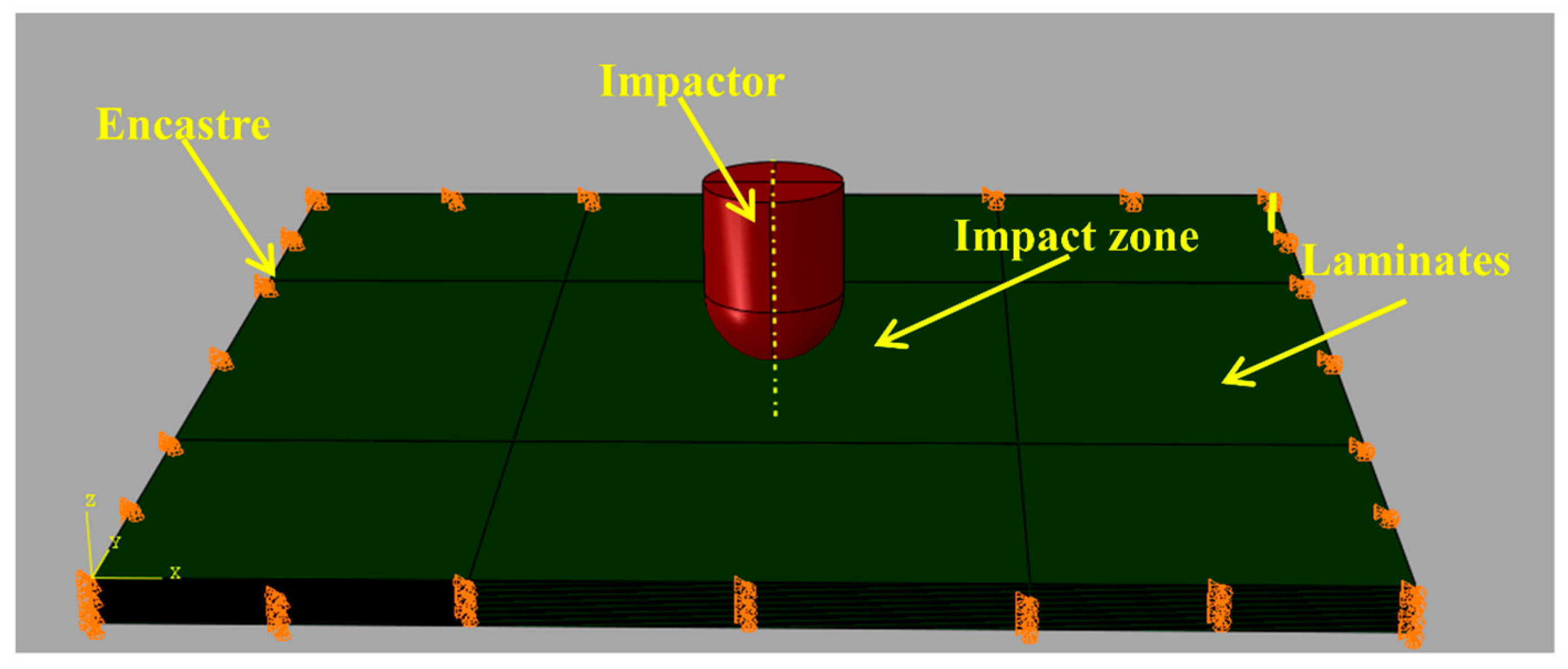
The ABAQUS 6.14 finite element analysis software was used to create a flat plate model and a punch model to simulate the low-velocity impact behavior of the composite plate. As shown in Figure 2, a flat plate with dimensions of 100 mm × 100 mm × 3.71 mm was created, with a carbon fiber layer thickness of 0.145 mm and a cohesive unit layer thickness of 0.01 mm [31]. A total of three material properties are included in the model, namely the carbon fiber layer material properties, the carbon fiber interlayer material properties, and the punch material properties, where the punch is a constrained rigid body and the carbon fiber layer is a homogeneous material. In addition to the properties assigned to the carbon fiber layers, a reference coordinate system is established for the material orientation of the carbon fiber layers, and a right-angle coordinate system is used to define the material orientation of the layers.
The entire model consists of 24 layers of carbon fiber and 23 layers of cohesive cells. The order of each fiber layer of unidirectional laminated laminate is [45/0/−45/90]3s and [±45/0/90/±45]2s, respectively, and then the plain weave is woven through the TEXGEN 3.12.2 software, and the corresponding equivalent material parameters are calculated in ABAQUS, and the plate is given this parameter to realize the impact simulation of the braided structure. The center area of the plate is divided into 20 mm × 20 mm squares for easy encryption in subsequent grids. The impact area of the grid is 1.5, and the area for the rest of the grids is 4. The interlayer cohesion element specifies its element type as COH3D8, and the carbon fiber layer mesh attribute is a fully integral mesh type.

2.3.2. Contact Definition and Material Properties

Carbon fiber is selected from T300. The properties of the materials are given in Table 1. The fiber structure of the carbon fiber sheets is divided into two types: woven and unidirectional carbon fiber lay-up. The thickness of the sheets is the same. The woven structure is plain weave, the non-woven structure has [45/0/−45/90]3s and [±45/0/90/±45]2s. Equivalent fiber bundle material parameters and equivalent fiber bundle material parameters [32] are given in Table 2.

2.4. Low-Velocity Impact Test

The carbon fiber of choice is T300, and the resin is 7901 epoxy resin. The fiber structure of the carbon fiber sheets is a woven structure and a carbon fiber unidirectional lay-up structure. The fiber volume fraction was 60%; the woven structure was plain woven; the non-woven structure was [45/0/−45/90]3s and [±45/0/90/±45]2s for three laminate specimens. The specimen size is 100 × 150 mm, with two unidirectional ply structures. The thickness of each layer of fiber is 0.125 mm, and the total thickness after making the laminate is about 3.7 mm, which is made by a molding process, and 4.44 mm for the plain-woven structure.
The impact test in this article refers to the ASTMD 7136 standard impact test method [33]. The instrument used in the test is the American Instron Dynatup 9250 HV drop weight testing machine, which is mainly equipped with specimen fixtures, operating platforms, and anti-secondary impact devices. The clamped specimen is fixed onto the rigid support. The test was conducted with a hemispherical steel punch with a diameter of 12.5 mm and a mass of 7.17 kg. The impact point is located at the center of the impacted specimen. The test operation, data acquisition, and analysis are carried out through the Impulse v4.x software, and the output test results include impact force time history curves, energy curves, etc. In this paper, the punch under different plates and different impact energies is consistent. According to the kinetic energy formula, the impact energy is controlled by controlling the impact speed of the punch, and the impact velocity corresponding to different impact energies is as follows: 2 J—0.75 m/s, 4 J—1.06 m/s, 6 J—1.30 m/s, and 8 J—1.50 m/s.

3. Results and Discussion

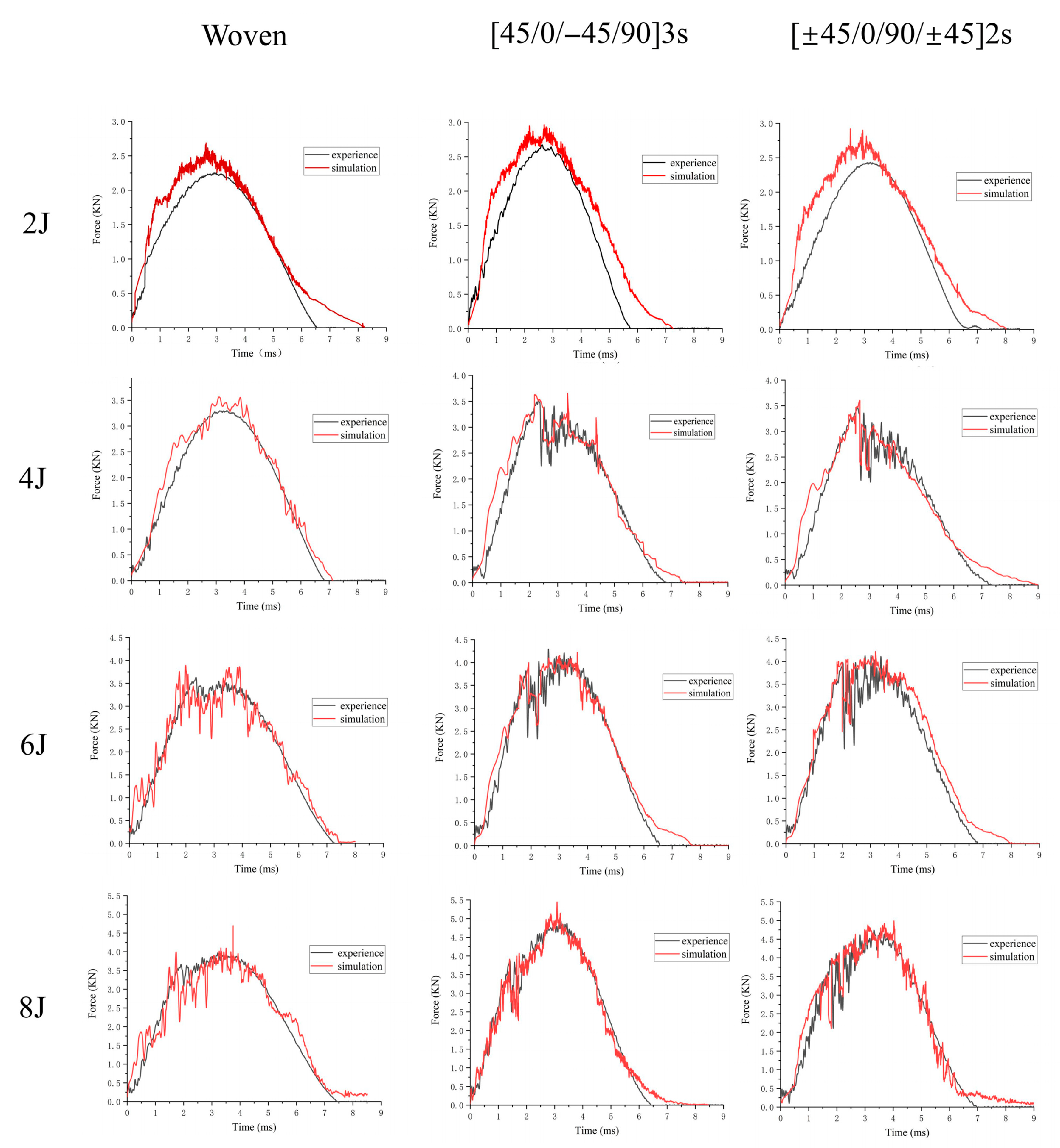
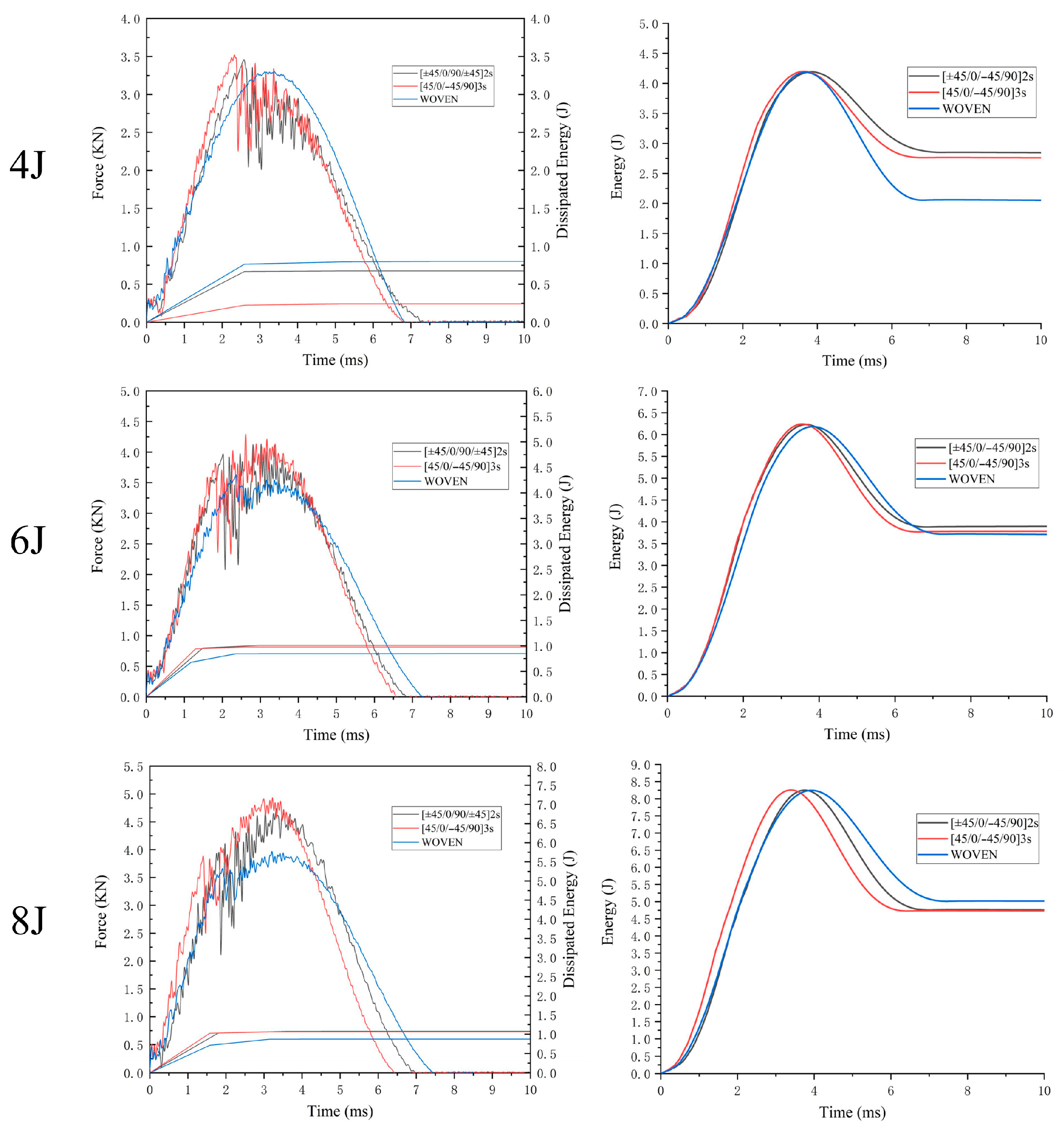
As shown in Figure 3, the curve fluctuation is obviously gentler at impact energy levels of 2 J and 4 J, while the curve displays obvious waveform vibrations at increased impact energy levels of 6 J and 8 J. At the 4 J energy impact of [45/0/−45/90]3s and [±45/0/90/±45]2s, the plain-woven plate will first shown an obvious steep decline trend in the contact force. That is, the phenomenon of obvious fiber fracture occurs [33], so the plate’s stiffness is reduced. Less force is required to maintain the subsequent deformation. The peak load is reached when the fiber break point appears with a lot of energy dissipated, after which the punch starts to bounce back and the contact force decreases. At the 6 J impact, however, the fiber break point is advanced to the maximum contact force before the fiber break point dissipates energy, after which the contact force continues to increase, the lower sheet continues to deform, and the number of matrix fiber cracks increases. The contact force reaches its maximum and then decreases to zero, where no new fiber fracture points appear.
The plain-woven structure only shows this phenomenon at 6 J because when the impact head is in contact with the specimen, the fibers around the impact point in all directions will be involved in the force, and the specimen will show high impact resistance. The fiber break point is obvious only when the impact load is high.
Comparing the impact contact force versus time for each ply structure at different impact energies, the curve trends are basically consistent with the finite element simulation results; i.e., the selected damage failure criterion and the degradation criterion are more reasonable. When comparing the laminates with the unidirectional paving structure, both show that the overall mechanical properties are stronger at [45/0/−45/90]3s than at [±45/0/90/±45]2s, and the curve fluctuations are smaller, which, when combined with the actual damage, means that fewer microcracks are produced during impact than at [±45/0/90/±45]2s, which is consistent with the increase in 45° paving mentioned in the literature [34], thereby increasing the stiffness of the plates. During high-energy impacts, the impact energy of [45/0/−45/90]3s is absorbed by most of the remaining various matrix fibers, and interface damage occurs at the same contact force, resulting in less damage to the lower layer, which is reflected in the more severe back bulge of [±45/0/90/±45]2s and longer and wider cracks than [45/0/−45/90]3s.
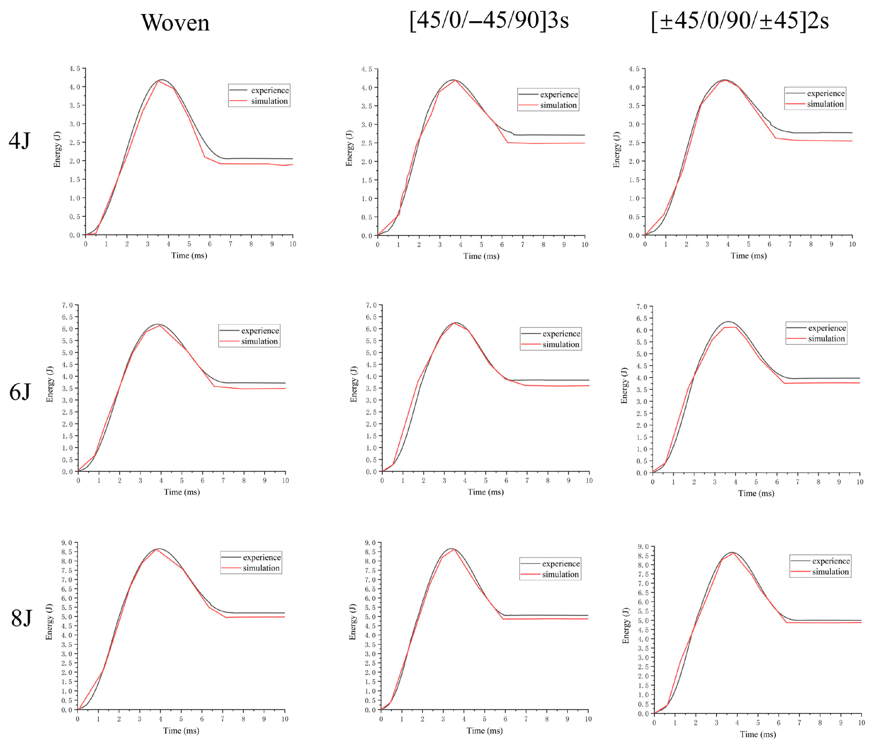
The experimental data on energy absorption is also in general agreement with the simulated data from Figure 4, with the actual energy absorbed in the experiment being slightly greater than that in the simulation due to heat and friction consumption. The impact energy–time curve shows that the energy absorption process of the specimen during impact is relatively low at the beginning when the transverse impact load makes the dent and deformation along the thickness direction relatively small. Afterwards the contact area between the impactor and the specimen increases, and the deflection increases or even causes internal damage with the rapid increase in energy. Finally the rebound of the punch ends, and the absorbed energy is constant. Generally the composite damage process defines the absorbed energy and the impact energy as Ea and Ei, respectively, and the degree of damage to the sheet after impact is assessed by comparing the damage variable DI (the ratio of absorbed energy (Ea) to impact energy (Ei)), which also reveals how the total impact energy starts and propagates energy through the specimen [35].
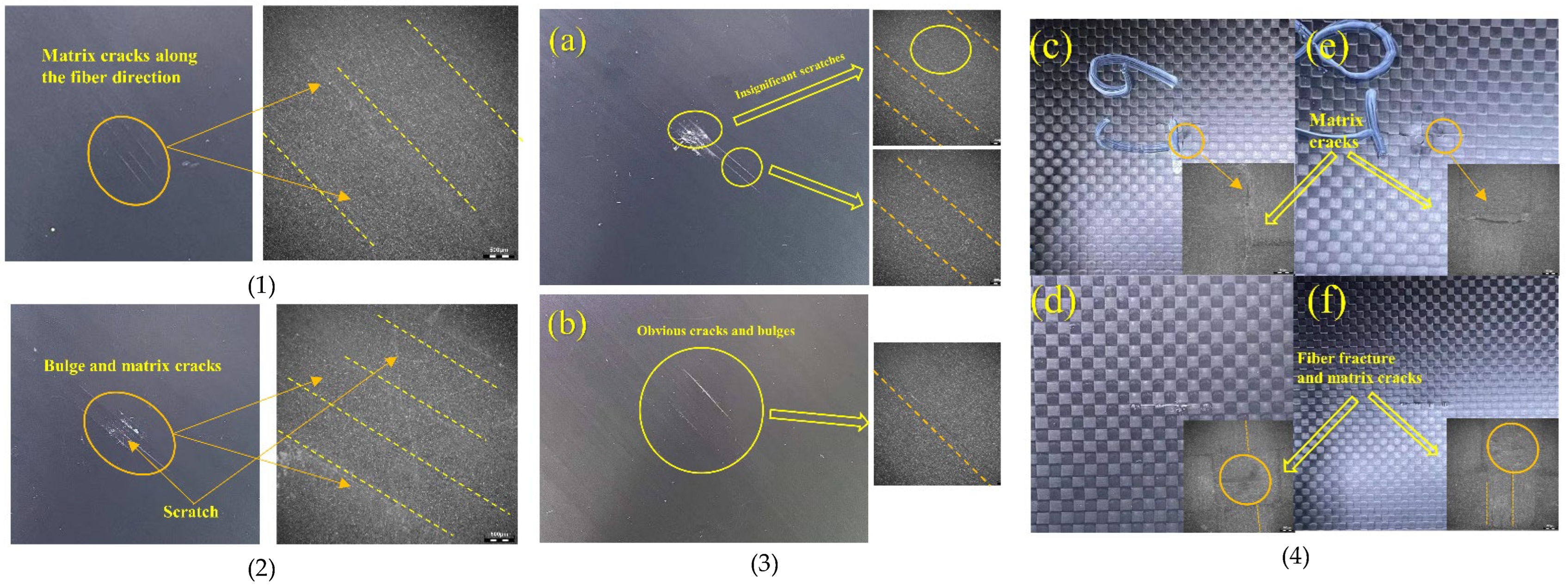
As shown in Figure 5, the damage is in the form of fractures of the fibers in the impact area and cracking of the matrix between the layers. The interweaving of the carbon fibers in each of the upper and lower layers of the plain fabric ply specimens is perpendicular to each other, and the warp and weft carbon fibers in each layer are interwoven with each other, with the interwoven mesh structure of each layer impeding the downward movement of the punch. Cracks are produced along the thickness direction and part of the delamination crack, indicating the occurrence of fracture of the fibers.
The unidirectional pavement specimens produced only a little crater on the impact surface compared to the plain pavement, and no obvious damage cracks were observed. The back bulge and crack width were more pronounced for [±45/0/−45/90]2s than for [45/0/−45/90]3s.
Regarding the unidirectional fabric laminate in the impact process, the fibers are not interwoven, the fibers are not constrained to each other, and the sub-ply located below is subject to greater tensile stress than the sub-ply above. So the side subjected to greater tensile stress causes inter-ply damage along the direction of expansion, resulting in a greater damage size, and the main damage is tensile damage, also known as matrix cracking. The cracking direction is basically parallel to the direction of the fibers; that is, the stiffness of the resin matrix between the fibers and strength is lower, as shown by the larger matrix tensile damage.
Let the braided structure be A, the [45/0/−45/90]3s structure be B, and the [±45/0/90/±45]2s structure be C.
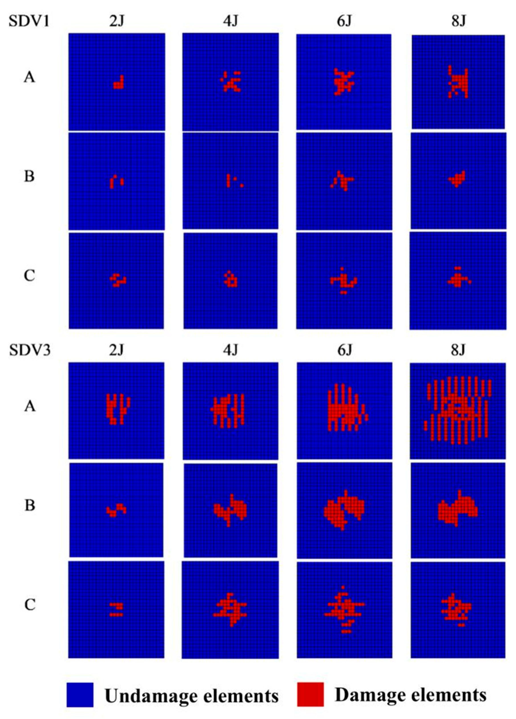
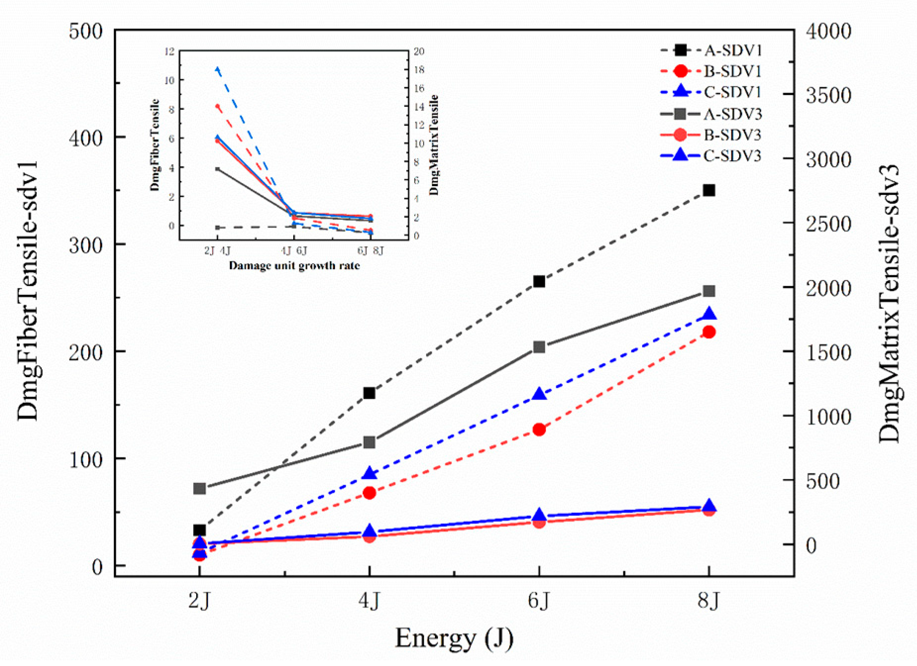
The damage of the laminate during the impact process is mainly caused by the compression damage of the matrix on the top of the plate and the tensile damage of the fibers on the back. And due to the different stress states of different layers, the failure forms are different. Therefore, the back fiber tensile damage unit (SDV1) and the surface matrix compression damage unit (SDV3) were selected for damage display; the tensile damage of the matrix in Figure 6 and Figure 7 accounts for the main body of the matrix damaged, and the number of damage units is also larger, and the matrix compression damage unit of B and C on the upper surface increases slightly with the increase in impact energy, while the fiber tensile damage and matrix compression damage of A increase significantly, and at 4−6 J, the damage units of the three plates increase significantly.
It is worth noting that we can see from Figure 6 that some of the damaged cells are not continuous, which is mainly due to the division of the cell grid and the complex damage mechanism of the composite laminate itself, which does not affect our use to discuss the change trend of damage. In addition, it is clear that there is more damage to A than to B and C. There is no visible damage at the 2 J impact; visual damage starts to appear at the 4 J impact; more visible macroscopic damage growth occurs at the 6 J impact, and damage growth slows down at the 8 J impact energy level. According to the contact force–time curves for both B and C unidirectional laminates, B is stronger than C in resisting fiber tensile fractures and matrix damage because the 45° angle plies are better able to disperse the contact forces during impact, thus allowing the internal fibers and matrix to reduce damage more effectively, while the plain-woven structure has a higher number of failed cells than the unidirectional laminate. The contact forces are dispersed by the interweaving of the fibers, resulting in significant damage to the matrix fibers.
However, the growth rate of damage cells is much lower in plain fabric laminates than in unidirectional laminates as the impact energy rises, indicating higher ductility and yielding, and also because they have higher inter- and intra-ply damage impedance relative to crossed unidirectional laminates, with the inherent interwoven structure being particularly significant in limiting crack propagation [36,37,38].
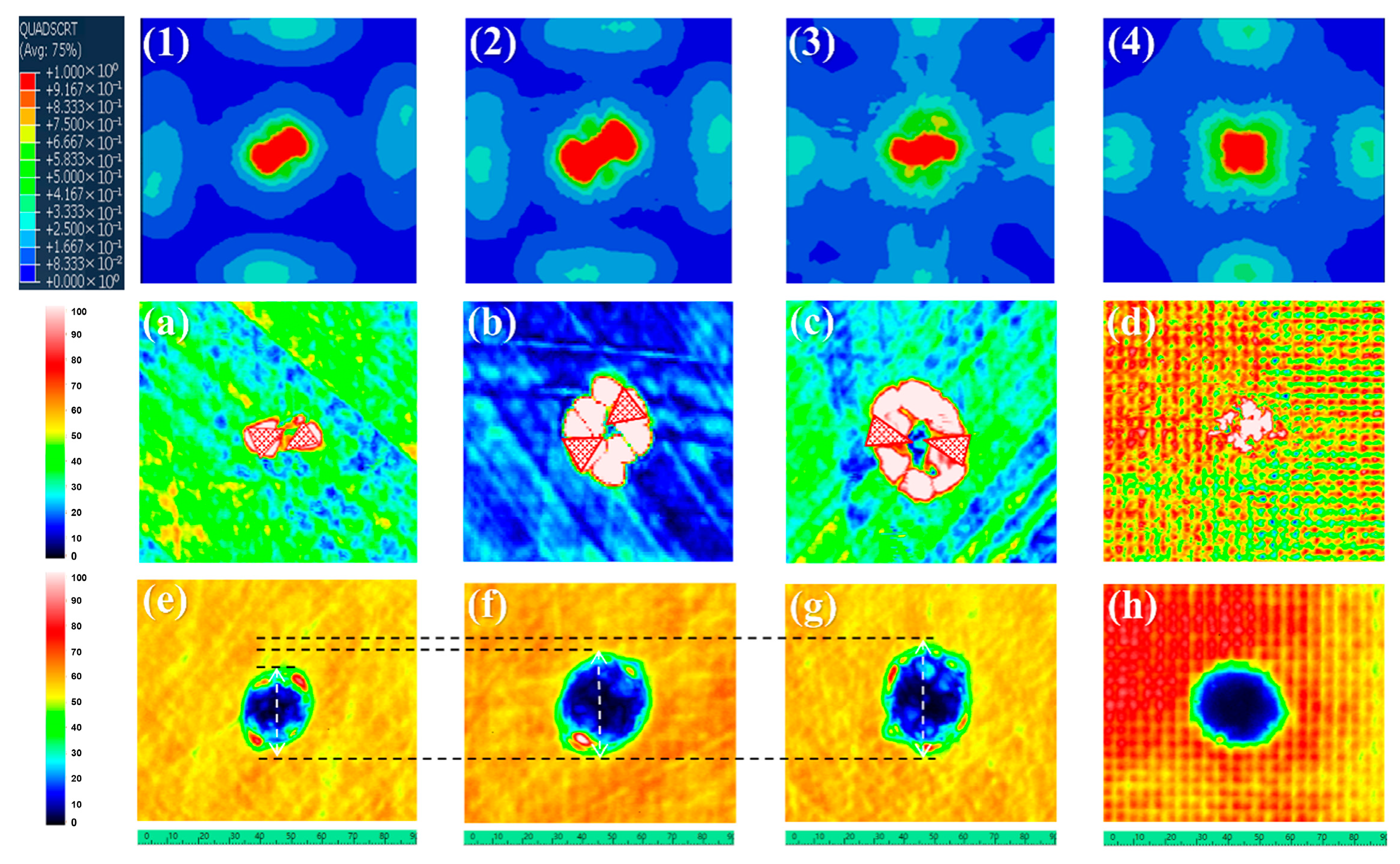
To observe the damage to the internal delamination of the composite laminate after low-speed impact, we used an ultrasonic C-scanner to scan. In this paper, an ultrasonic flaw detector from Beijing Polaris Company is used, model BSN-C0505, and the probe frequency is 5 MHz. The testing process refers to GB/T 18694-2002 [39] and other relevant test standards, the results are shown in Figure 8.
The damage surface shapes of the [45/0/−45/90]3s and [±45/0/90/±45]2s structures after impact were diamond-shaped or cross-shaped, extended in the direction of each angle, and were concentrated around the centerline of the impact point, while according to Figure 8 (the delamination damage clouds and C-scan images), the greater the impact energy, the greater the delamination area, and the growth of the delamination range from 4 J to 6 J in impact energy is significantly greater than that from 6 J to 8 J. The delamination damage of the plain-woven laminate has a more uniform circular shape, and the delamination damage of the plain-woven structure is smaller and more concentrated.
The impact damage of composite materials with plain fabric plies shows that the damage is concentrated in the center of the impact area and that the damage area is small, while the damage in the impact area inside the laminate is mostly fiber fractures and resin cracking. The impact damage of unidirectional fabric laminates is characterized by smaller impact damage on the impact surface but a larger internal damage area, with the internal impact area of the laminate mostly being the interlayer delamination crack damage near the impact surface.
Comparing the energy absorption conditions of the three structural plates under different impact energies, it can be seen that the value of the plain-woven structure after energy absorption stabilization is significantly smaller than the remaining two unidirectional ply plates at the 4 J energy impact, but according to its actual macroscopic damage, the upper surface is similar to the upper surface of the remaining two plates, and there are only a few small cracks around the crater and no obvious damage to the back, which is less damaged compared to the unidirectional ply plates, indicating energy absorption. The results of the comparison curves are the same, while the energy absorption values of [45/0/−45/90]3s are greater than [±45/0/90/±45]2s at different energy impacts, which is related to the angle of lay-up. At 4 J, the crack failure energy curve reflects that there may be more invisible cracks in their plain-woven panels, but at the 6 and 8 J energy impacts, there are fewer cracks in the plain-woven panel structure. The stable values of crack failure energy for [±45/0/90/±45]2s at different energy impacts are significantly greater than [45/0/−45/90]3s; i.e., it is assumed that the number of cracks in the plates differs due to their lay-up angle and lay-up structure, affecting the damage state and energy absorption, thus making the crack energy values different.
Based on the comparison in Figure 9, the damage starts to appear from the time the punch touches the laminate and when the crack failure energy of the three structures is dissipated at a steady rate. The three mechanical response curves gradually stabilize the failure energy dissipation rate after the fiber break point is reached, after which if the contact force curve continues to rise, the crack failure energy curve also rises slightly and is basically completely stable after the maximum contact force.
In addition, the crack failure energy curves of laminates with different lay-up structures under the same energy impact show different degrees of increase, and the higher the impact energy, the greater the slope of the curve increase; i.e., the crack failure energy is dissipated faster, which is related to the structural differences in the laminate, leading to different degrees of damage to the matrix fibers and delamination damage. The failure energy proposed in this paper can therefore describe to a certain extent the extent of damage within the composite plate and the effect of some microcracks on the plate, which are not easily observed, making the assessment of plate damage more accurate.
Fracture energy is an inherent property of the material and is consistent with fracture toughness. The energy release rate is the actual crack expansion parameter and is a dynamically evolving variable that indicates the amount of energy required to advance the crack a certain length. EDE is defined as the energy loss due to crack damage and to some extent characterizes the energy absorbed by the damage.
The transformation and absorption of energy in CFRP laminates during impact can be divided into three phases according to the characteristics of the forces and displacements, namely the laminate deformation phase, the laminate damage phase, and the impact rebound phase. The absorbed energy corresponds to the elastic specific energy Ee, the damage absorbed energy Ed, and the punch rebound energy Er, while in the impact process, there are also other energy absorption methods such as microcracks Ev, etc. Energy dissipation in the inelastic process is mainly manifested in the composite laminate in the actual impact process due to delamination, matrix cracking, and the absorbed energy, so E e + E d = E 0 . Energy dissipation in the composite laminate during the actual impact is mainly due to delamination and matrix cracking, where
E a = E e + E d + E v = E 0 + E v .
E v = E a E 0 .
Calculation of Ev: Assuming that the absorbed energy is negative, the friction energy is not counted, and the failure mechanism is uniform throughout the thickness, each layer of fibers acts independently. The failure of fibers in one layer does not affect the other layers, and the material properties remain unchanged during the impact, and the strain rate is constant. According to the range of crater section damage in the literature [40,41], the energy absorbed in the layers can be calculated using the following formula:
E D L = π R C 2 G I I C h .
The energy equation for matrix cracking is expressed by calculating the following:
E M C = π R C 2 E m t l V m .
In addition the fibers break mainly in the tensile mode, so for the entire failure area of the unidirectional pavement, the energy absorbed by the fibers in tensile damage can be expressed as follows:
E T F = π R C 2 h / 4 E C .
However, in a plain-woven structure, there is a transfer of released elastic strain energy around the crater due to the breakage of the primary yarn, assuming that the strain from the center of the laminate to the boundary of the delamination zone is R = 2 Rc. The strain within the secondary yarn varies linearly, and the primary load is tensile. The equation for the energy absorbed in the elastic deformation of the second yarn per unit area is as follows:
E E D = π 2 r 2 σ f 2 / E f 0 2 R C r h d r = π 2 r 2 σ f 2 / E f R c 2 h E C .
The energy equation for matrix cracking of woven structures is expressed as
E M C = 1 / 3 · π R C 2 E m t l V m .
The energy absorption equation for a unidirectional ply structured laminate is as follows:
E 0 = E D L + E M C + E T F = π R c 2 G I I C + E C / 4 h + E m t V m l ,
Woven structures are expressed as follows:
E 0 = E D L + E M C + E T F + E E D = π R c 2 G I I C + E C / 4 + π r 2 σ f 2 / E f h + 1 / 3 · E m t V m l ,
where R C is the crater radius, h is the crater depth, d is the punch diameter, l is the laminate width, Vm is the matrix volume fraction of the composite, Emt is the matrix cracking energy per unit volume of the composite, EC is the energy required to damage the fibers under tensile loading, G I I C is the crack fracture toughness, E f is the tensile modulus, σ f is the tensile strength, and r is the fiber radius.
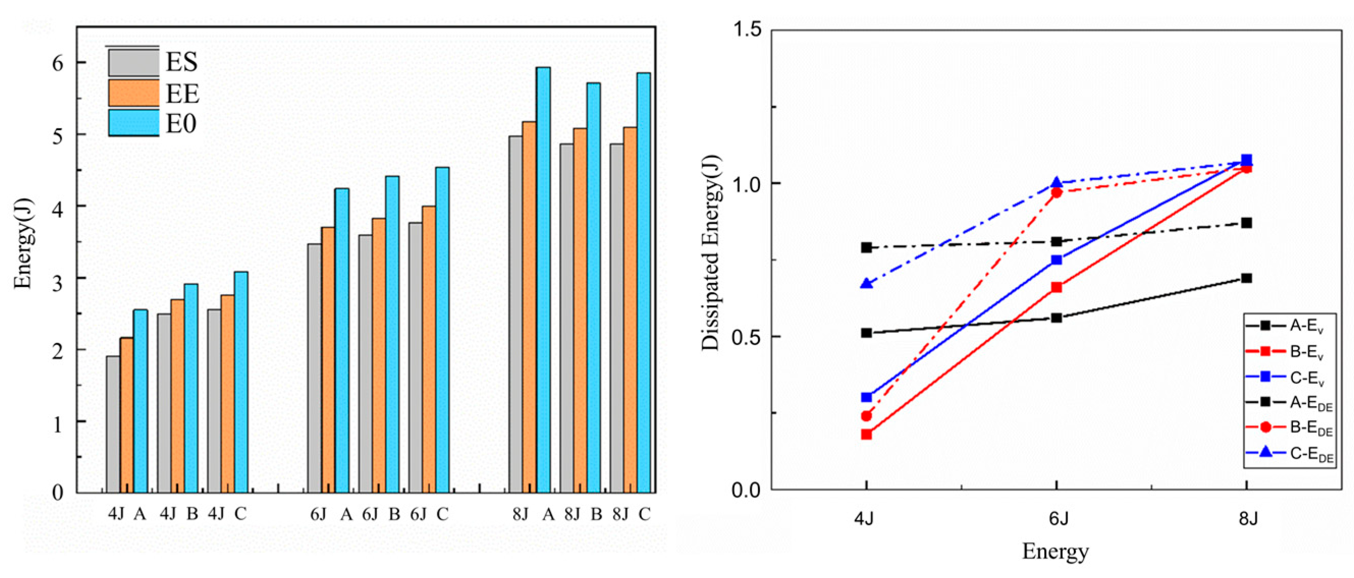
In Figure 10, ES is the value of E0 obtained from the simulation results, EE is the value of E0 obtained from the experimental results, and E0 is calculated from the above equation, where the calculated value of E0 is reasonably accurate to the value obtained from the experiment; i.e., the equation is consistent with the actual energy situation and can be used as a reference for inference.
In contrast, the crack failure energy of the plain-woven structure was greater than that of the large unidirectional pavement structure at an impact energy of 4 J. The contact force–time curve showed that there was no obvious damage to the plain-woven structure during the impact, but there were many invisible microcracks in the matrix and fibers [42]. As the impact energy increases, the fracture of the fiber matrix becomes the main damage at 6 J and 8 J. The crack failure energy of the plain-woven structure is slightly less than that of the unidirectional pavement structure, while the energy absorption curve shows that the energy absorption of the plain-woven structure is similar to or slightly greater than that of the unidirectional pavement structure, which is also due to the fact that some of the energy transferred from the punch to the plain-woven structure starts to transfer to the surrounding at a slower rate, causing the energy to be concentrated and resulting in more fracture damage to the matrix fibers. The energy absorbed by the cracks will be less than that of the unidirectional laminate structure.
For unidirectional laminate structures, the greater the impact energy, the smaller the difference between the change in crack failure energy and the change in energy absorption due to the angle of the pavement. However, the increase in the ±45° angle of the pavement for unidirectional laminate structures causes a corresponding change in crack failure energy dissipation due to the homogenization of stress transfer, leaving a strong influence on the delamination damage.
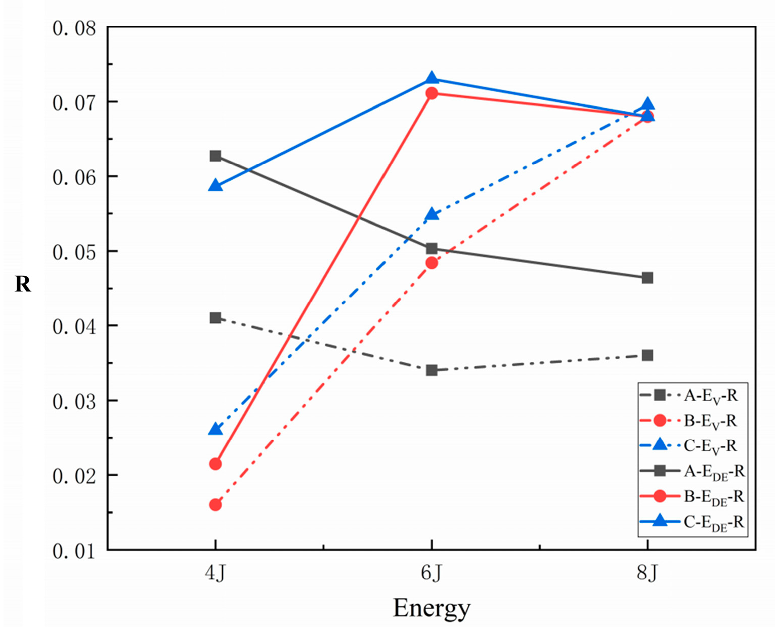
To illustrate the crack damage during fractures and to assess the damage state, this paper proposes the use of a combination of crack damage energy levels to characterize the degree of damage to the sheet in some way. The higher the crack failure energy, the more obvious the damage to the fiber matrix and the more obvious the damage state. As the impact energy increases, the rate of change in crack damage energy becomes smaller while the damage resistance becomes better. The variable R = E D E / E I × D i / D P e n e t r a t i o n is proposed. A larger R-value leads to a greater proportion of cracks in the matrix. A smaller R-value leads to a worse damage state of the laminate when compared to the crack failure energy graph. The use of R-value characterization can take into account the effect of impact displacement and can amplify the change in crack energy in relation to the different structures as the impact energy changes, thus making the damage assessment using crack failure energy more obvious and accurate. The change in R-value for the three composites at different impact energies is shown in Figure 11 and is consistent with the curve change for the sudden increase in damage between 4 J and 6 J described in the simulations above.
In combination with the above simulations and experiments, changes in stress conduction and energy distribution due to the addition of unidirectional plies at ±45° angles or changes to the plain-woven structure of the unidirectional plies are important reasons for the corresponding changes in failure energy dissipation.
The stiffness and load-bearing capacity of each structure during impact and the ability of the matrix fibers to absorb energy have a certain influence on the effect of the crack dissipation energy on the characterization of the damage. In the case of unidirectional paving, changing the paving angle has little effect on the characterization effect, and the change in paving angle can also be reflected by the response of the crack dissipation energy. Changing the structure of the plate has a greater impact, making the inflection point of the characterization effect less obvious.

4. Conclusions

In this paper, the changes in dynamic energy absorption capacity and damage failure behavior of the T300/7901 epoxy resin laminate in different structures, including the plain weave structure, [45/0/−45/90]3s, and [45/0/90/45]2s, after being subjected to low-speed impacts were investigated to provide some reference for composite design and damage determination in practical engineering applications. In this paper, the feasibility verification of using crack energy as an internal damage criterion is verified by combining the test with the finite element method and the ultrasonic C-scan detection method. The main conclusions are as follows:
1.
The impact of obtaining carbon fiber laminates with three different structures is as follows:
The two tables below are the main research conclusions of this paper, and the content of Table 3 helps us choose the application scheme of composite materials with better impact resistance in engineering problems, and the role of the 45° angle ply is described, providing guidance for our future composite ply design. The characterization or predictive performance indicators proposed in Table 4 have been scientifically and reliably verified in this paper, allowing us to study the damage problem of the plate without damaging the inside of the plate and reduce the cost of damage detection, as this paper has high accuracy, financial viability, and flexibility; has the potential for a wide range of applications; and can play a huge role in the engineering problem of damage detection of fiber composite structures to ensure engineering safety.
2.
The following representation methods are proposed:
Table 4. The characterization method proposed in this paper.
IndexCharacterization
The increase in cracks based on the crack dissipation energyThe performance of cracks in the overall damage.
The damage state of the plate can be predicted to some extent.
The change in failure energyA reference to describe the impact of damage deformation on the unidirectional ply and woven structured panels.
R-value combined with crack energyPredict the impact damage resistance of each structural laminate (more accurately).
This paper also has certain limitations. Firstly, this paper mainly simulates the change in the overall crack dissipation energy during the macroscopic impact process, and the germination and propagation process of cracks is more complex with the occurrence of the impact process at the microscopic level, so the microscopic manifestations of cracks can be considered in the future. In addition, this paper mainly studies the situation of a single impact; in fact, components often face the problem of multiple impacts in engineering problems, so it is of great significance to study the damage problem under multiple impacts, which is also our future research direction.

Author Contributions

Conceptualization, X.M.; methodology, X.M.; software, X.M. and Y.S.; validation, C.F.; formal analysis, Y.S.; investigation, Y.S.; resources, X.M.; data curation, Y.S.; writing—original draft preparation, Y.S.; writing—review and editing, Y.D.; visualization, C.F.; supervision, X.M.; project administration, K.M.; funding acquisition, X.M. All authors have read and agreed to the published version of the manuscript.

Funding

This research was funded by [the National Science Foundational of China] grant number [21703153] And The APC was funded by [Tianjin Key Laboratory of Fastening Joint Technology Enterprise].

Data Availability Statement

Data will be made available upon request.

Acknowledgments

The authors would like to thank the technical and academic staff of the Tianjin Engineering Center of Near-Net-Shape Forming Technology for Metallic Materials for their support of the work. The authors acknowledge the financial support provided by Tianjin Key Laboratory of Fastening Joint Technology Enterprise.

Conflicts of Interest

The authors declare that they have no known competing financial interests or personal relationships that could have appeared to influence the work reported in this paper.

References

  1. Liu, H.; Falzon, B.G.; Tan, W. Experimental and numerical studies on the impact response of damage-tolerant hybrid unidirectional/woven carbon-fibre reinforced composite laminates. Compos. Prart. B Eng. 2018, 136, 101–118. [Google Scholar] [CrossRef]
  2. Marsh, G. Aero engines lose weight thanks to composites. Reinf. Plast. 2012, 56, 32–35. [Google Scholar] [CrossRef]
  3. Yan, L.; Xu, H. Lightweight composite materials in automotive engineering: State-of-the-art and future trends. Alex. Eng. J. 2025, 118, 1–10. [Google Scholar] [CrossRef]
  4. Islami, D.P.; Muzaqih, A.F.; Adiputra, R.; Prabowo, A.R.; Firdaus, N.; Ehlers, S.; Braun, M.; Jurkovič, M.; Smaradhana, D.F.; Carvalho, H. Structural design parameters of laminated composites for marine applications: Milestone study and extended review on current technology and engineering. Results Eng. 2024, 24, 103195. [Google Scholar] [CrossRef]
  5. Alam, M.J.; Abedin, M.J.; Rahman, M.Z. Nanoparticles, nanocomposites, green/eco-composites, and hybrid composites and their applications in energy sectors. In Comprehensive Materials Processing, 2nd ed.; Hashmi, S., Ed.; Elsevier: Amsterdam, The Netherlands, 2024; pp. 321–339. [Google Scholar]
  6. Yang, F.; Cantwell, W. Impact damage initiation in composite materials. Compos. Sci. Technol. 2010, 70, 336–342. [Google Scholar] [CrossRef]
  7. Wang, M.; Shi, L.; Pan, Z.; Wu, Z. Mechanical response and damage mechanism of carbon/Kevlar hybrid braiding composite laminates under quasi-static indentation and low-velocity impact loading. Thin-Walled Struct. 2025, 213, 113291. [Google Scholar] [CrossRef]
  8. Zheng, K.; Cao, D.; Hu, H.; Chen, H.; Cai, W.; Li, S. Comprehensive investigation on modelling of low-velocity impact damage response of composite laminates—Experimental correlation and assessment. Compos. Struct. 2024, 345, 118412. [Google Scholar] [CrossRef]
  9. Faggiani, A.; Falzon, B. Predicting low-velocity impact damage on a stiffened composite panel. Compos. Part A Appl. Sci. Manuf. 2010, 41, 737–749. [Google Scholar] [CrossRef]
  10. Gliszczynski, A.; Kubiak, T.; Wawer, K. Barely visible impact damages of GFRP laminate profiles—An experimental study. Compos. Part B Eng. 2019, 158, 10–17. [Google Scholar] [CrossRef]
  11. Ellis, T.S.; Karasz, F.E. Interaction of epoxy resins with water: The depression of glass transition temperature. Polymer 1984, 25, 664–669. [Google Scholar] [CrossRef]
  12. Guha, R.D.; Rahmani, F.; Berkowitz, K.; Pasquinelli, M.; Grace, L.R. Temporal evolution of the behavior of absorbed moisture in a damaged polymer-quartz composite: A molecular dynamics study. Comput. Mater. Sci. 2022, 214, 111690. [Google Scholar] [CrossRef]
  13. Ibekwe, S.; Li, G. Low Velocity Impact Damage on Laminated Polymer Composites. In Encyclopedia of Materials: Plastics and Polymers; Hashmi, M.S.J., Ed.; Elsevier: Amsterdam, The Netherlands, 2022; pp. 241–266. [Google Scholar]
  14. Zheng, X.; Wu, Y.; Zheng, C.; Bai, H.; Liu, R. Quasistatic and low-velocity impact properties of entangled metallic wire material–silicone rubber composites. J. Mater. Res. Technol. 2023, 23, 3856–3868. [Google Scholar] [CrossRef]
  15. Luo, Z.; Wang, H.; Ng, C.-T.; Fu, J.; Zhang, Z.; Wang, C. On the low-velocity impact properties of CFRP/HAFRP interlayer hybrid fibre composite laminates. Eng. Struct. 2024, 315, 118387. [Google Scholar] [CrossRef]
  16. Chen, X.; Peng, Y.; Wang, K.; Wang, X.; Liu, Z.; Huang, Z.; Zhang, H. Experimental and simulation study on bonded repaired low-velocity impact of carbon fiber reinforced plastic laminates for rail vehicles. J. Mater. Res. Technol. 2023, 28, 446–458. [Google Scholar] [CrossRef]
  17. Lyu, Q.; Wang, B.; Guo, Z. Predicting post-impact compression strength of composite laminates under multiple low-velocity impacts. Compos. Part A Appl. Sci. Manuf. 2023, 164, 107322. [Google Scholar] [CrossRef]
  18. Jing, K.; Zhou, H.; Wang, H.; Yan, H.; Xie, S. Multiscale damage and low-velocity impact study of three-dimensional woven composites. Thin-Walled Struct. 2024, 202, 112132. [Google Scholar] [CrossRef]
  19. Li, N.; Du, J.; Lee, H.M.; Liu, W.; Zheng, Y.; Lee, H.P. Damage characterization and modelling of FRP laminated composites subjected to external edge-on impact. Compos. Part B Eng. 2024, 287, 111819. [Google Scholar] [CrossRef]
  20. Li, X.; Liu, P.; Cheng, H.; Liu, C.; Zhu, Y.; Zhang, K. Experimental and numerical analysis of low-velocity impact damage of CFRP laminates with negative Poisson ratio (NPR) rubber protective layer. Thin-Walled Struct. 2023, 191, 111066. [Google Scholar] [CrossRef]
  21. Zhao, Y.; Zhou, X. Numerical analysis of unidirectional carbon-fibre/epoxy composite laminates under low velocity impacts of different forms. Comput. Mater. 2024, 231, 112611. [Google Scholar] [CrossRef]
  22. Wang, G.; Zhang, L.; Xuan, S.; Fan, X.; Fu, B.; Xue, X.; Yao, X. An efficient surrogate model for damage forecasting of composite laminates based on deep learning. Compos. Struct. 2024, 331, 117863. [Google Scholar] [CrossRef]
  23. David-West, O.; Nash, D.; Banks, W. An experimental study of damage accumulation in balanced CFRP laminates due to repeated impact. Compos. Struct. 2008, 83, 247–258. [Google Scholar] [CrossRef]
  24. Yao, T.; Li, D.; Jiang, L. Parametric theoretical prediction of elastic properties and strength of fine weave pierced C/C composites. Compos. Struct. 2023, 325, 117614. [Google Scholar] [CrossRef]
  25. Russo, A.; Palumbo, C.; Riccio, A. The role of intralaminar damages on the delamination evolution in laminated composite structures. Heliyon 2023, 9, e15060. [Google Scholar] [CrossRef]
  26. Shao, M.; Cai, D.A.; Yu, Q.; Xing, D.; Hu, F.; Kuang, N.; Zhou, G. On mechanical properties of double-sided-loop 2D woven laminated composites. Compos. Struct. 2023, 312, 116874. [Google Scholar] [CrossRef]
  27. Kim, H.B.; Naito, K.; Oguma, H. Mode II fracture toughness of two-part acrylic-based adhesive in an adhesively bonded joint: End-notched flexure tests under static loadinG. Fatigue Fract. Eng. Mater. Struct. 2017, 40, 1795–1808. [Google Scholar] [CrossRef]
  28. Barile, C.; Casavola, C.; Gambino, B.; Mellone, A.; Spagnolo, M. Mode-I Fracture Behavior of CFRPs: Numerical Model of the Experimental Results. Materials 2019, 12, 513. [Google Scholar] [CrossRef]
  29. Han, J.; Lei, L.; Liu, S.; Zhang, J. Fatigue damage analysis and life prediction of 3D braided SiC/SiC composites with multi-scale approach. Compos. Struct. 2024, 349–350, 118447. [Google Scholar] [CrossRef]
  30. SIMULIA ABAQUS, Version 6.14-5; Dassault Systèmes: Providence, RI, USA, 2014.
  31. Zhang, T. Research on Repair Performance of T300/7901 Carbon Fiber Composite Laminate. Master’s Thesis, Tianjin University of Technology, Tianjin, China, 2023. [Google Scholar] [CrossRef]
  32. Zhao, Q.L.; Hou, Y.L.; Liu, Z.; Li, C. Multi-scale modeling of the low-velocity impact and compression after impact behaviors of plain woven carbon-fiber-reinforced composites. China Mech. Eng. 2021, 32, 1732–1742. [Google Scholar]
  33. ASTM D7136/D7136M-20; Standard test method for measuring the damage resistance of a fiber-reinforced polymer matrix composite to a drop-weight impact event. ASTM International: West Conshohocken, PA, USA, 2020.
  34. Hongkarnjanakul, N.; Bouvet, C.; Rivallant, S. Validation of low velocity impact modelling on different stacking sequences of CFRP laminates and influence of fibre failure. Compos. Struct. 2013, 106, 549–559. [Google Scholar] [CrossRef]
  35. Cao, Y.; Cai, Y.; Zhao, Z.; Liu, P.; Han, L.; Zhang, C. Predicting the tensile and compressive failure behavior of angle-ply spread tow woven composites. Compos. Struct. 2020, 234, 111701. [Google Scholar] [CrossRef]
  36. Khashaba, U.A. A comprehensive study of low-velocity impact behavior and damage evaluation of angle-ply thin woven GFRP composites under elevated temperatures. Compos. Sci. Technol. 2024, 252, 110608. [Google Scholar] [CrossRef]
  37. Xiao, J.; Bathias, C. Fatigue behaviour of unnotched and notched woven glass/epoxy laminates. Compos. Sci. Technol. 1994, 50, 141–148. [Google Scholar] [CrossRef]
  38. Curtis, P.T.; Bishop, S.M. An assessment of the potential of woven carbon fibre-reinforced plastics for high performance applications. Composites 1984, 15, 259–265. [Google Scholar] [CrossRef]
  39. GB/T 18694-2002; Chinese Standard. Non-destructive testing--Ultrasonic inspection--Characterization of search unit and sound field. State General Administration of the People’s Republic of China for Quality Supervision and Inspection and Quarantine: Beijing, China, 2002.
  40. Liu, M.; Pan, Q.; Gao, M.; Luo, C.; Tang, Z.; Sun, Z. Experimental study of the impact damage pattern of carbon fiber reinforced resin matrix composite laminates. Failure Anal. Prev. 2016, 11, 283–288+299. [Google Scholar] [CrossRef]
  41. Hongbo, H. Investigation of Constituents Damage and Interface Strength of Laminate Made of Carbon Fiber Woven Fabrics. Master’s Thesis, Tianjin University of Technology, Tianjin, China, 2019. [Google Scholar]
  42. Yuan, K.; Shen, L.; Xiong, W.; Yao, S.; He, J.; Wang, Z. The impact and post-impact flexural behaviors of CFRP/aluminum-honeycomb sandwich. Int. J. Impact Eng. 2023, 174, 104507. [Google Scholar] [CrossRef]
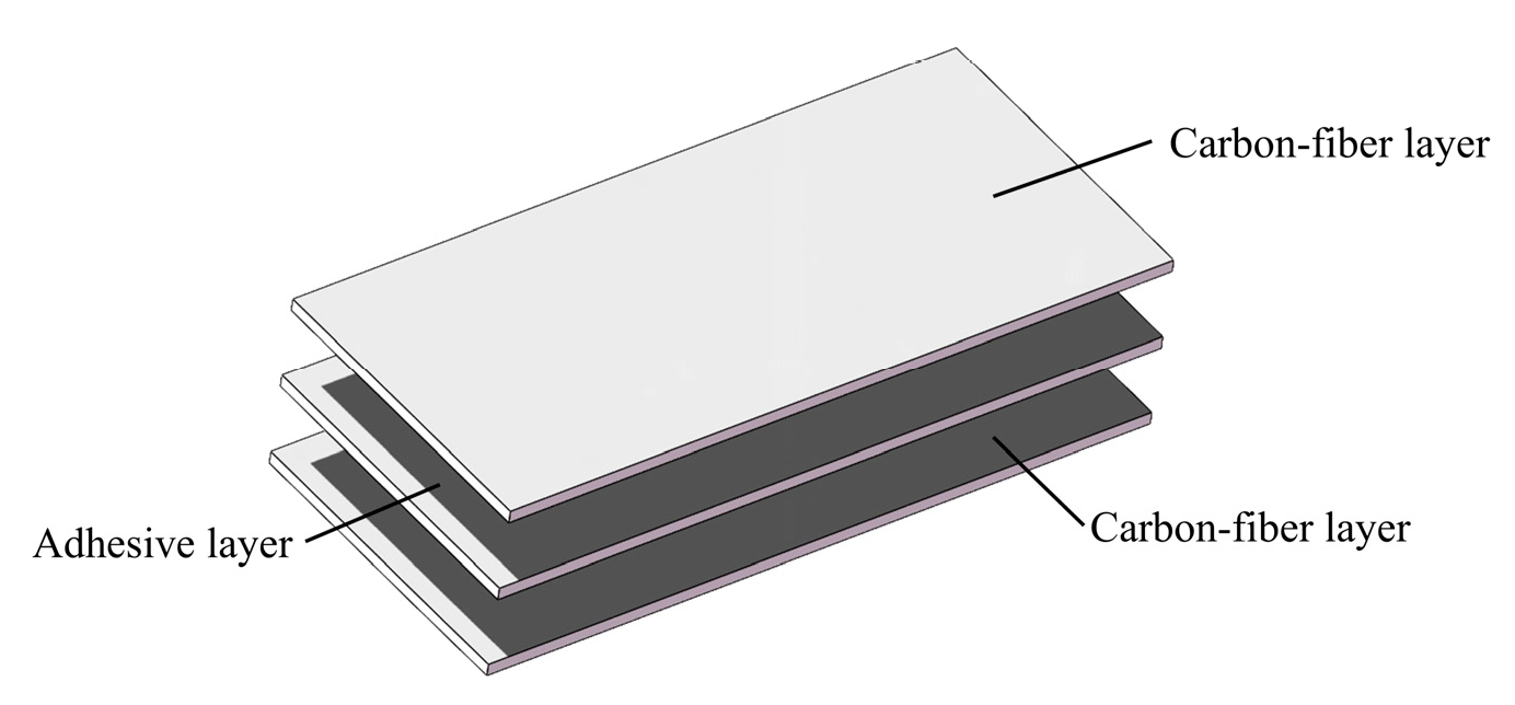
Figure 1. Schematic diagram of laminate layering.
Fibers 13 00115 g001
Figure 2. Schematic diagram of finite element model.
Fibers 13 00115 g002
Figure 3. Comparison diagram of experimental and simulated contact forces under four energy shocks.
Fibers 13 00115 g003
Figure 4. Experimental and simulated energy comparison diagrams for four energy shocks.
Fibers 13 00115 g004
Figure 5. The macroscopic damage and microscopic matrix fiber damage images after the impact test, where (1) and (2) are the images of [45/0/−45/90]3s under the 4 J and 6 J impacts, respectively; (a,b) in (3) are the images of [45/0/−45/90]3s and [±45/0/−45/90]2s under the 8 J impact, respectively; and (4) is the front and back sides of the damage images of the woven fiber under the 6 J (c,d) and 8 J (e,f) impacts on the plate, (c,e) show the impact pit, (d,f) show the back crack.
Fibers 13 00115 g005
Figure 6. The diagrams show the simulated matrix damage and fiber damage after each energy impact.
Fibers 13 00115 g006
Figure 7. Matrix fiber damage unit count variation table.
Fibers 13 00115 g007
Figure 8. Panels (13) show the delamination damage of [45/0/−45/90]3s at the 4 J, 6 J, and 8 J impact energy levels, and (4) shows the delamination damage of the woven structure at the 8 J impact energy level; (ad) show the corresponding C-scan slice scans at the same depth, and (eh) show their overall bottom wave field images, where (14) are the results of simulation, and (ah) are the results of the ultrasound C-scan.
Fibers 13 00115 g008
Figure 9. Failure energy versus contact force–time graphs and energy–time graphs for three different structures with different energy impacts.
Fibers 13 00115 g009
Figure 10. Comparison of energy absorption from simulations, analytical calculations, and experimental results and comparison of EV and EDE. EDE is the crack dissipation energy reading in the impact simulation, and EV is the dissipation energy of the crack in the experiment; it is calculated by bringing Equations (27) and (28) into Equation (21).
Fibers 13 00115 g010
Figure 11. The graph shows the change in R-value for the 4 J, 6 J, and 8 J shocks.
Fibers 13 00115 g011
Table 1. T300 unidirectional carbon fiber lay-up structure material parameters and interlaminar parameters.
Carbon Fiber LayerCohesive
E1/GPa138E11 = 100,000
E2/GPa9.31
E3/GPa9.31
G12/GPa4.81E22 = 100,000
G13/GPa4.81
G23/GPa5
υ120.32E33 = 100,000
υ130.32
υ230.45
Table 2. Equivalent fiber bundle material parameters and equivalent fiber bundle material parameters.
Elastic ConstantsStrength Parameters
Ey11/G Pa184.771tensile strength XyT/MPa2890
Ey22 = Ey33/GPa19.172Compression strength XyC/MPa2065
Gy12 = Gy13/GPa8.462tensile strength YyT/MPa92
Gy23/GPa6.760Compression strength YyC/MPa187
υ12 = υ130.28Shear strength Sy12 = Sy13/MPa107
υ230.42Shear strength Sy23/MPa61
Table 3. Impact performance of carbon fiber laminates with three different structures.
Plain Woven[45/0/−45/90]3s[±45/0/90/±45]2s
The number of failed cellsmaxminmid
The growth rate of damage cellslowerhigher
Delamination damagesmaller and more
concentrated.
diamond-shaped or cross-shaped
Impact damagesmaller area and more
concentrated.
a smaller impact damage
a larger internal damage area
Macroscopic damagea few small cracks around the crater and no obvious damage to
the back
more damage
Crack dissipation energy4 J: The woven structure was greater.
6 J 8 J: The woven structure is slightly smaller.
Resistance to impact damagemaxmidmin
Major reasons1. The interwoven mesh structure of each layer impeding the downward movement of the punch.
2. The ±45° angle of unidirectional lay-up causes the uniformity of stress transfer to affect delamination damage.
Disclaimer/Publisher’s Note: The statements, opinions and data contained in all publications are solely those of the individual author(s) and contributor(s) and not of MDPI and/or the editor(s). MDPI and/or the editor(s) disclaim responsibility for any injury to people or property resulting from any ideas, methods, instructions or products referred to in the content.