Article

The Effect of Carbon Nanotubes and Carbon Microfibers on the Piezoresistive and Mechanical Properties of Mortar

by
Irene Kanellopoulou
1,*,
Ioannis A. Kartsonakis
1,2,*,
Athanasia I. Chrysanthopoulou
1 and
Costas A. Charitidis
1
1
Research Unit of Advanced, Composite, Nano-Materials and Nanotechnology, School of Chemical Engineering, National Technical University of Athens, 9 Heroon Polytechniou St., Zographos, GR-15773 Athens, Greece
2
Physical Chemistry Laboratory, School of Chemistry, Aristotle University of Thessaloniki, GR-54124 Thessaloniki, Greece
*
Authors to whom correspondence should be addressed.
Fibers 2024, 12(8), 62; https://doi.org/10.3390/fib12080062
Submission received: 12 June 2024 / Revised: 27 July 2024 / Accepted: 29 July 2024 / Published: 31 July 2024
(This article belongs to the Collection Feature Papers in Fibers)

Abstract

:
Sustainability, safety and service life expansion in the construction sector have gained a lot of scientific and technological interest during the last few decades. In this direction, the synthesis and characterization of smart cementitious composites with tailored properties combining mechanical integrity and self-sensing capabilities have been in the spotlight for quite some time now. The key property for the determination of self-sensing behavior is the electrical resistivity and, more specifically, the determination of reversible changes in the electrical resistivity with applied stress, which is known as piezoresistivity. In this study, the mechanical and piezoresistive properties of mortars reinforced with carbon nanotubes (CNTs) and carbon micro-fibers (CMFs) are determined. Silica fume and a polymer with polyalkylene glycol graft chains were used as dispersant agents for the incorporation of the CNTs and CMFs into the cement paste. The mechanical properties of the mortar composites were investigated with respect to their flexural and compressive strength. A four-probe method was used for the estimation of their piezoresistive response. The test outcomes revealed that the combination of the dispersant agents along with a low content of CNTs and CMFs by weight of cement (bwoc) results in the production of a stronger mortar with enhanced mechanical performance and durability. More specifically, there was an increase in flexural and compressive strength of up to 38% and 88%, respectively. Moreover, mortar composites loaded with 0.4% CMF bwoc and 0.05% CNTs bwoc revealed a smooth and reversible change in electrical resistivity vs. compression loading—with unloading comprising a strong indication of self-sensing behavior. This work aims to accelerate progress in the field of material development with structural sensing and electrical actuation via providing a deeper insight into the correlation among cementitious composite preparation, admixture dispersion quality, cementitious composite microstructure and mechanical and self-sensing properties.

1. Introduction

Cementitious-based materials are widely used in the construction engineering field due to their low cost, rich resources and high compressive strength. These materials are very popular because they can easily be produced and used locally and have good environmental adjustability [1,2]. However, such constructions are subjected to deterioration due to erosion and corrosion processes. Therefore, cement composite materials are reinforced using several fillers such as carbon nanotubes (CNTs), carbon nanofibers (CNFs) and microfibers (CMFs), inorganic nanoparticles, graphene oxides, etc. The incorporation of these fillers aims to improve the mechanical as well as electrical and thermal properties of the produced composite materials [3]. The enhancement of mechanical properties leads to constructions with increased mechanical integrity, whereas the enhancement of electrical properties renders them with self-sensing properties. As a result, smart and sustainable infrastructures with improved service life, reliability and durability are developed [4].
CNTs attain exceptional properties, which are attributed to their unique structure, namely their enhanced mechanical properties (high tensile strength (11–63 GPa), elastic modulus (270–950 GPa), stiffness) combined with their low density (2.1 g/cm3) and extremely elevated surface area. Additionally, they have high electrical (106–107 S/m) and thermal conductivity (3000–3500 W/m·K) while being chemically stable in most aggressive mediums and thus being corrosion-resistant [5]. Carbon nanotubes are widely used as cement-reinforcing materials because of their enhanced mechanical properties, as mentioned earlier, and carrying capacities due to the presence of sp2 hybrid orbitals in their covalently bonded C atoms, along with their high aspect ratio and fiber-like structure. Their high electrical conductivity, which is attributed to their π C-C bonds on the z-plane, can potentially reinforce the piezoresistive properties of cementitious materials containing them [6]. According to the literature, CNTs embedded into concrete act as bridges across voids and cracks, forming interfacial bonds with cement, thus resulting in compressive strength improvement [7,8,9]. Similar outcomes have been observed in studies by Haddad et al. [10], Li et al. [11] and Wang et al. [12]. The direct fabrication of CNTs on clinker so as to be employed in cement-based materials is also mentioned in the literature by Calixto’s research group [13]. In the work of Moon et al. [14], it is stated that the effective dispersion of CNTs in ultra-high-performance concrete leads to, on the one hand, a remarkable enhancement in electrical conductivity and, on the other hand, the formation of a denser structure with improved mechanical properties with respect to stiffness.
Carbon fibers are also widely used as fillers for cement composites due to their unique properties such as fatigue, creep, corrosion and high temperature resistance. Moreover, their chemical stability and electrical conductivity, along with their light weight and high specific strength, enable the usage of CMFs as fillers in concrete. The work of Gao et al. reported that the mechanical properties of cement-based composites with respect to flexural strength are enhanced and the resistivity is decreased after the incorporation of CMFs [15]. Chuang et al. stated that the CMF concentration influences the conductivity of cement-based composites [16]. The work of Diaz et al. indicated that the incorporation of short CMFs in cement paste results in a reduction in resistance [17]. In the research of Wang et al., it was revealed that both the bending strength and conductivity of cement-based composites are improved with better CMF distribution [18].
Over the last few years, both CNTs and CMFs have received increasing interest as fillers. Lee et al.’s research group found that both CMF and CNT incorporation in cementitious composites improves the stability of the electrical resistivity of the composites [19]. The embedment of them into cementitious-based materials imparts improvement in their final mechanical properties with respect to flexural and compressive strength. Moreover, the electrical resistivity of the materials varies during a loading–unloading procedure, indicating the material’s sensing capability. In the work of Yoon et al., the synergistic effect of CMFs and CNTs that were added into cement composites was investigated with respect to their electromagnetic wave shielding properties [20].
However, an important factor that influences the final behavior of cementitious-based materials is the dispersion quality of the CNTs and CMFs in the matrix. More specifically, pristine CNTs do not exhibit sufficient dispersion when incorporated into different matrices [5,21,22,23,24]. Agglomerates of CNTs and CMFs are formed during the dispersion process due to their intrinsic hydrophobic surfaces, their high rigidity and their chemical inert behavior, all due to π-π bonds between the carbon atoms of their lattices, which are very strong. The π-π bond strength is also affected by the specific structure of CNTs. Namely, according to their synthesis techniques/methodologies, single-wall CNTs (SWCNTs) or multi-wall CNTs (MWCNTs) can be produced. SWCNTs are considered hollow cylinders that are produced by rolling a single graphite sheet in such a way that their ends meet. Their diameter and length are approximated as 2 nm and 2 μm, respectively, while their bandgap ranges between 0 and 2 eV. MWCNTs comprise 2–10 coaxial graphene layers so that their diameter and length are >10 nm and 0.5–50 μm, respectively. Consequently, it can be deduced that the overall efficiency of CNT incorporation in composite materials is highly dependent on several morphological characteristics, such as size, shape and classification, according to their structure, namely if they are SWCNTs or MWCNTs [5]. Thus, many attempts have been made to improve the dispersibility of CNTs and CMFs in cement composites. In the literature, there are several studies reporting on the employment of silica fume as a dispersing agent for cement fillers such as CNTs and CMFs [25,26]. Silica fume can enhance the strength of concrete because of its chemical composition. It has been proven that concrete that contains silica fume can preserve its strength for a long time. The positive effect of silica fume is attributed to its spherical-shaped particles that penetrate into the cementitious composites and increase the distance between the fillers [27,28]. Kim et al. found that the incorporation of silica fume in concrete led to the enhancement of its mechanical and electrical properties because of the improvement in CNT dispersion [29]. Stynoski et al. showcased that the use of silica fume enhanced the mechanical properties of mixtures containing CNTs and CMFs, denoting a stronger frictional bond between the reinforcement agent and the matrix [30]. In the work of Chuang et al., it was revealed that the addition of silica fume into cement-based composites positively affected the CMF dispersion and was correlated with an increase in the electrical conductivity of the composites [16]. Furthermore, several other studies have proven that the addition of silica fume to either mortar or concrete results in an increase in the dispersion of CNTs and CMFs, which subsequently leads to improved electrical and mechanical properties for the composites [31,32]. In the work of Song et al., it was revealed that CNTs’ dispersibility in mortar was improved by increasing the replacement ratio of silica fume [27]. The use of polycarboxylate-based stabilizers additionally provides a positive effect on the dispersibility of CNTs and CMFs in the cement paste without deteriorating or destroying their structures [33,34,35,36]. This type of stabilizer acts as an effective dispersion agent because of its long lateral ether chains, which impart steric repulsion between the fillers in cement-based composites [37].
Moreover, since in the case of CNTs, their reactivity, solubility, dispersion and overall performance depend highly on their surface properties, as CNTs interact interfacially via their surfaces with any potential mediums, different approaches to CNT surface modifications have been examined extensively in the literature. These surface modifications via the introduction of functional groups onto the external (exohedral) or internal (endohedral) walls of CNTs are introduced with the term “functionalization”. At this time, there are a vast variety of methodologies for the functionalization of CNTs, which have been thoroughly examined. More specifically, there is covalent and non-covalent functionalization, which act as the two subcategories of exohedral functionalization and endohedral functionalization. In the covalent functionalization of CNTs, chemical groups are either directly attached onto their surface (e.g., fluorination, hydrogenation and 1,3-dipolar cycloadditions, electrophilic addition, etc.) or via the derivatization of already existing functional groups. In covalent functionalization, chemical groups are incorporated onto CNTs’ surfaces via chemical reactions that change sp2 carbon bonds to sp3 bonds, thus affecting the core properties of CNTs, while in non-covalent functionalization, hydrogen bonding, π-π stacking and Van der Waals forces are the dominant forces developed as part of the physical reactions between CNTs and substances like the polymeric dispersants of surfactants. The latter scenario is realized without affecting the stricture of the CNTs. The use of dispersants is considered a case of non-covalent CNT functionalization [38,39,40]. Endohedral functionalization has attracted considerable research interest since the interior tube, bounded by CNT walls, constitutes an area where different substances can be incorporated and bind strongly (with high binding energy) and where chemical reactions that do not take place elsewhere can take place. Up to now, metals, fullerenes and other substances such as halogens have been reported to be encapsulated into CNTs [39,41].
The motivation behind the present work is the development of cementitious-based composite materials with structural sensing and electrical actuation along with enhanced mechanical properties. The aim of this work is to identify structural changes in mortar and determine how properties can be enhanced by the incorporation of CNTs and CMFs together with silica fume. More specifically, their effect on the mechanical properties and electrical conductivity of the cementitious matrix as a function of their concentration is estimated. Mortar test specimens were prepared, comprising a range of CNT and CMF concentrations by weight of cement (bwoc). The surface morphology of the prepared and fractured cement specimens was evaluated via SEM, while an elemental analysis was performed via energy-dispersive X-ray analysis. The macro-mechanical integrity was investigated with respect to flexural and compressive strength (EN 196-1 [42]). The results revealed that the CNTs, CMFs and dispersing agent content influenced the mechanical properties and electrical conductivity of the mortar specimens. Finally, it may be remarked that the added value of this work resides in the fact that the presented results shed light on current and future opportunities to accelerate progress in the field of material development with structural sensing and electrical actuation.

2. Materials and Methods

2.1. Materials

Analytical reagent-grade chemicals were used. Portland Cement CEM I 52.5 N was used as cementitious material; its physical properties and chemical composition are summarized in Table 1. Sand (NORMENSAND CEN-Standard Sand DIN EN 196-1 [42]) and silica fume (Sika® Silicoll P) were used as aggregates, whereas SIKA SI100 (a polymer with polyalkylene glycol polymer graft chains) was used as a stabilizer. Multi-walled carbon nanotubes (CNTs) were fabricated through the catalytic thermal chemical vapor deposition method (CT-CVD), according to our previous works [43,44]. Finally, the CMFs were received from R&G Faserverbundwerkstoffe GmbH (chopped carbon fiber strands 3 mm).

2.2. Synthesis of Reinforced Mortars

Mortar samples including CNTs and CMFs were fabricated according to the EN 196-1 standard [42] using Portland Cement CEM I 52.5 N [45] as cementitious material. Regarding the piezoresistivity tests, prismatic test samples 40 mm × 40 mm × 160 mm in size with electrodes embedded into them were fabricated (in triplicate) (Figure 1). Concerning the conductivity tests, prismatic test samples 40 mm × 40 mm × 160 mm in size were prepared (in triplicate).
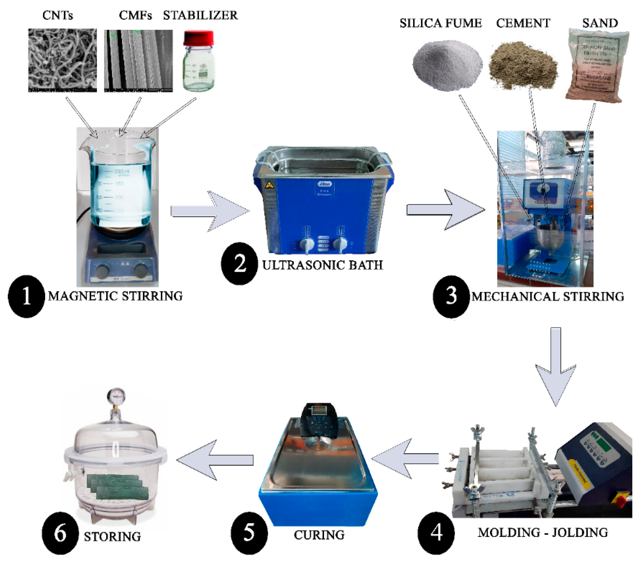
The CNTs were incorporated into the aforementioned mixture as additives at several concentrations bwoc. Based on ground work and preliminary tests that have been conducted by the authors, CNTs were dispersed in water prior to their incorporation in mortars with the aid of the SIKA SI100 stabilizer. In the aforementioned preliminary tests, using a stabilizer proved to give rise to more stable suspensions of CNTs in water vs. time. In detail, the methodology followed entails the addition of CNTs in a beaker containing the desired amount of water (total w/c must remain at 0.5) and SIKA SI100 stabilizer (max. conc. 0.3% bwoc) under vigorous stirring with a magnetic stirrer. Subsequently, the suspension was subjected to ultrasonic treatment for 45 min and then added into the stirring bowl together with cement powder, sand and silica fume. Prior to the preparation of the composite samples, the surface of the CNTs was functionalized by chemical modification, introducing oxygen-containing groups such as hydroxyl (–OH), carboxyl (–COOH) and carbonyl (C=O) groups. The functionalization of CNTs is described in detail in our previous work [44]. Briefly, the surface of the fabricated CNTs was functionalized with –COOH groups via the use of an acid solution mixture of sulfuric acid and nitric acid (H2SO4:HNO3 3:1). The CNT–acid solution mixture underwent vigorous stirring for 5 h, and then the mixture was centrifuged, and the obtained functionalized CNTs were rinsed with water and acetone and left to dry. This modification promoted the wettability of the CNTs and the bonding between their surfaces with the hydration products. The mortar was prepared by mechanical mixing and was compacted in a Teflon mold using a jolting apparatus. The specimens in the mold were kept at room temperature conditions for 24 h, and then the demolded specimens were placed under water for a curing period of 28 days. Figure 2 illustrates the aforementioned synthetic procedure. According to the aforementioned procedure, CNT-reinforced mortar specimens, CMF-reinforced mortar specimens and CNT/CMF-reinforced mortar specimens were fabricated using the parameters tabulated in Table 2, Table 3 and Table 4, respectively.
The aim was to evaluate the influence of both CNTs and CMFs together with silica fume in the mortar specimens with respect to their mechanical and piezoresistive properties. Silica fume, which was selected to be incorporated into the mortar specimens, improved the mechanical properties of the mortar due to the increase in the secondary hydrated reactions with Ca(OH)2, resulting in the formation of C-S-H gel [25,27,46]. The chosen concentration of CMFs for the fabrication of the CNT/CMF-reinforced mortar specimens was 0.4% bwoc (Table 4) because the Mortar-0.4% CMF specimen demonstrated the best flexural strength value of all the CMF-reinforced mortar specimens (as it is discussed in detail in Section 3.2. Mechanical Properties).

2.3. Characterization

The morphology of the additives and the mortar specimens was estimated via scanning electron microscopy (SEM) using a Hitachi Electron Microscope TM3030 coupled with an Ultra-High-Resolution Scanning Electron Microscope (UHR-SEM) and a NOVA NANOSEM 230 (FEI Company, Hillsboro, OR, USA, 2009) equipped with an Energy-Dispersive X-ray Spectrophotometer (EDS) (QUANTAX 70, BRUKER, Billerica, MA, USA, 2016).
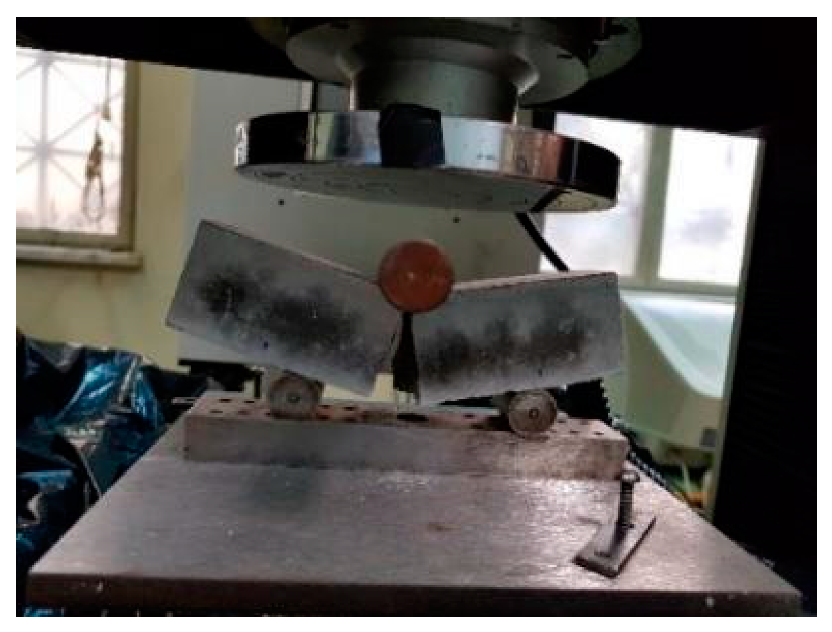
The macro-mechanical integrity was investigated by means of flexural strength (EN 196-1 [42]) using a material testing machine to apply loads (Instron 1121, load accuracy: ±0.5% of the reading) with a displacement rate (speed) of 1 mm/min (Figure 3) and by means of compressive strength (EN 196-1 [42]) using an INSTRON 300DX-B1-C4-G6C (load accuracy: ±0.5% of the reading) with a displacement rate (speed) of 5 mm/min (Figure 4). It is mentioned that for the compressive strength tests, the specimens that were used were the prism halves from the flexural strength tests [47].
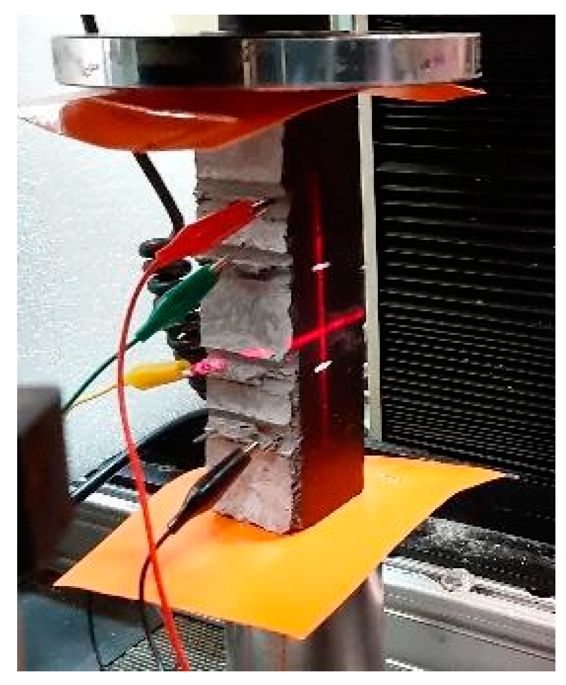
The piezoresistive response properties of the aforementioned CNT-reinforced mortar specimens, CMF-reinforced mortar specimens and CNT/CMF-reinforced mortar specimens were evaluated using a data acquisition system via the four-probe method. The dimensions of the prismatic samples were 40 mm × 40 mm × 160 mm, with stainless steel mesh electrodes embedded into them. The resistivity was measured as a function of the cyclic load in order to evaluate the self-sensing properties of the produced mortar samples. The aim of using relative resistance measurements under cyclic loading is to monitor the material’s sensing capability during a loading–unloading procedure. The electrical measurements were obtained using a Keithley Source-Meter 2400 (0.012% basic measure accuracy with 6½-digit resolution), together with a material testing machine applying loads (Instron 1121). In each measurement, a fixed direct current (DC) of 1 mA was applied to the outer two electrical contacts, while the voltage drop between the inner electrical contacts was measured (Figure 5). The displacement rate (speed) was 1 mm/min, the cyclic load ranged from 0.2 kN to 9.5 kN (a pre-stress was applied equal to 0.2 kN), and a laser extensometer, Fielder Optoelektronik Κ-100, was used to accurately measure the displacement. Then, the relative change in the electrical resistance, Δ R R ο (fractional change in resistance, FCR), as a function of time was recorded under repeated compressive loading, where R0 is the initial electrical resistance of the specimens, with a compressive loading equal to 0.2 kN at the beginning of the experiment. The results can be depicted as either a function of load or as a function of stress. In order to eliminate the effect of the electric polarization and depolarization of cement-based materials on the compressive sensitivity testing results, enough time was left to pass until the voltage value became stable. The resistivity, ρ , of the modified mortar sample was calculated by Equation (1):
ρ = R S l
where S is the effective area of the voltage pole (the cross-sectional area), l is the space between the two voltage poles (the length of the material being tested in the direction of the resistance, R), and R is the electrical resistance [or volume (bulk) resistance].
Then, the FCR is given by Equation (2):
F C R = Δ R R ο = Δ ρ ρ ο + Δ l l o ( 1 + v 1 + v 2 )
where Δ l l o is the compressive strain, and v 1 and v 2 are the values of the Poisson’s ratio in the two transverse directions [34]. According to Equation (2), ΔR depends on both Δρ and Δl. It is assumed that the resistance change is a indication of the piezoresistivity; therefore, Δ ρ ρ ο >> Δ l l o , and, subsequently, Equation (2) becomes the following:
F C R = Δ R R ο = Δ ρ ρ ο
The effect of sensing on the inherent piezoresistivity (an evaluation indicator of the sensitivity of the strain sensor) is described by the gauge factor (GF), which is defined as the FCR per unit strain (Equation (4)). The GF constitutes a means of evaluating the inherent piezoresistivity of a material, having exemplified the irreversible resistivity changes due to impairment or permanent microstructure alterations. In this work, the GF is determined via the four-probe method, which, as indicated in the literature, constitutes a safer and more accurate approach compared to the two-probe method [48,49].
G F = Δ R R ο Δ l l o = Δ ρ ρ ο Δ l l o

3. Results

3.1. Morphological and Structural Characterization

SEM images of the produced CNTs and the utilized CMFs are illustrated in Figure 6a,b, respectively. In the case of the produced CNTs, the SEM image reveals that they are tangled and distributed randomly. They appear in varying sizes, and their diameter ranges between 14 and 45 nm. In the case of the CMFs, the SEM image depicts that their diameter is roughly 6.9 ± 0.2 μm.
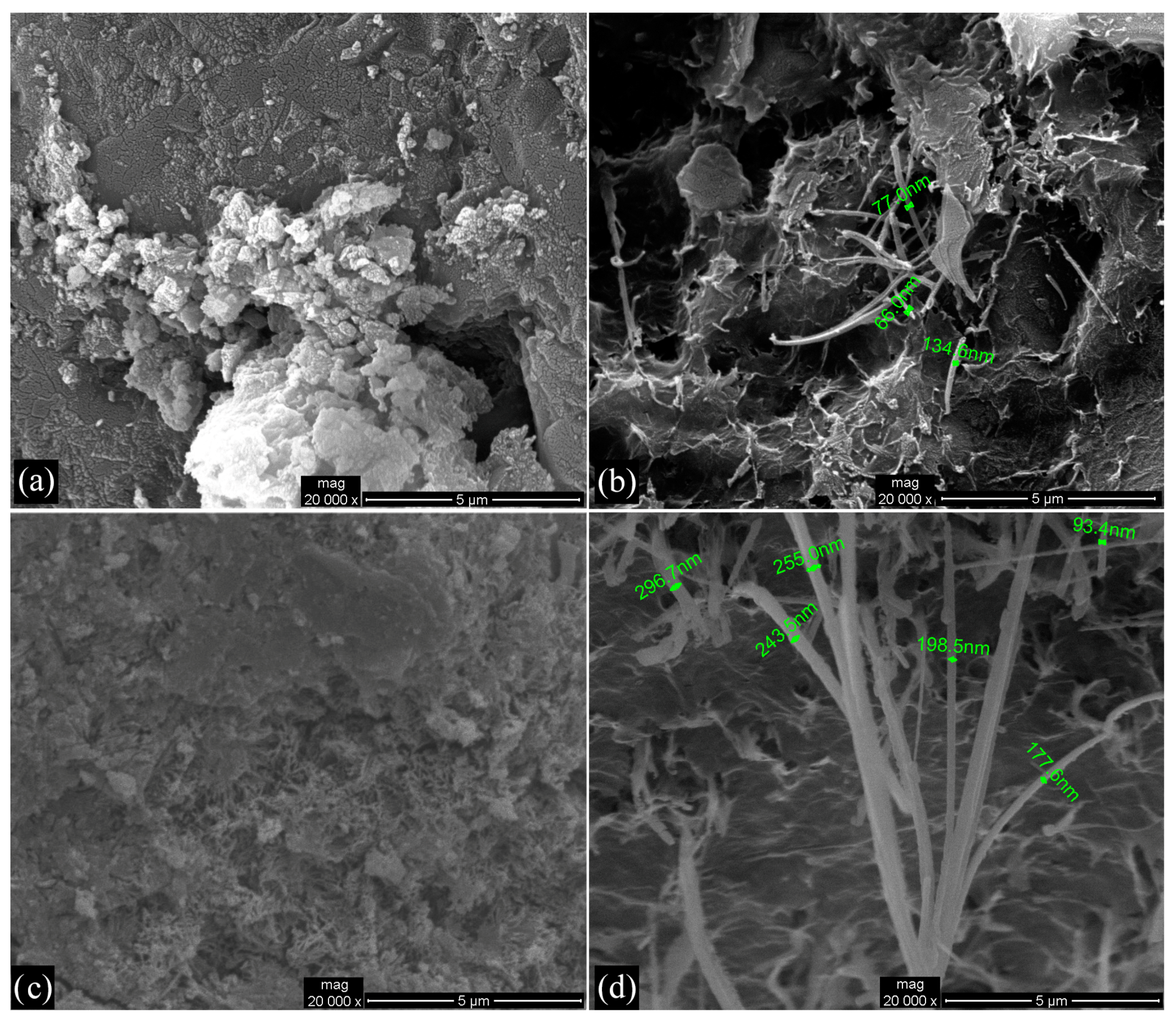
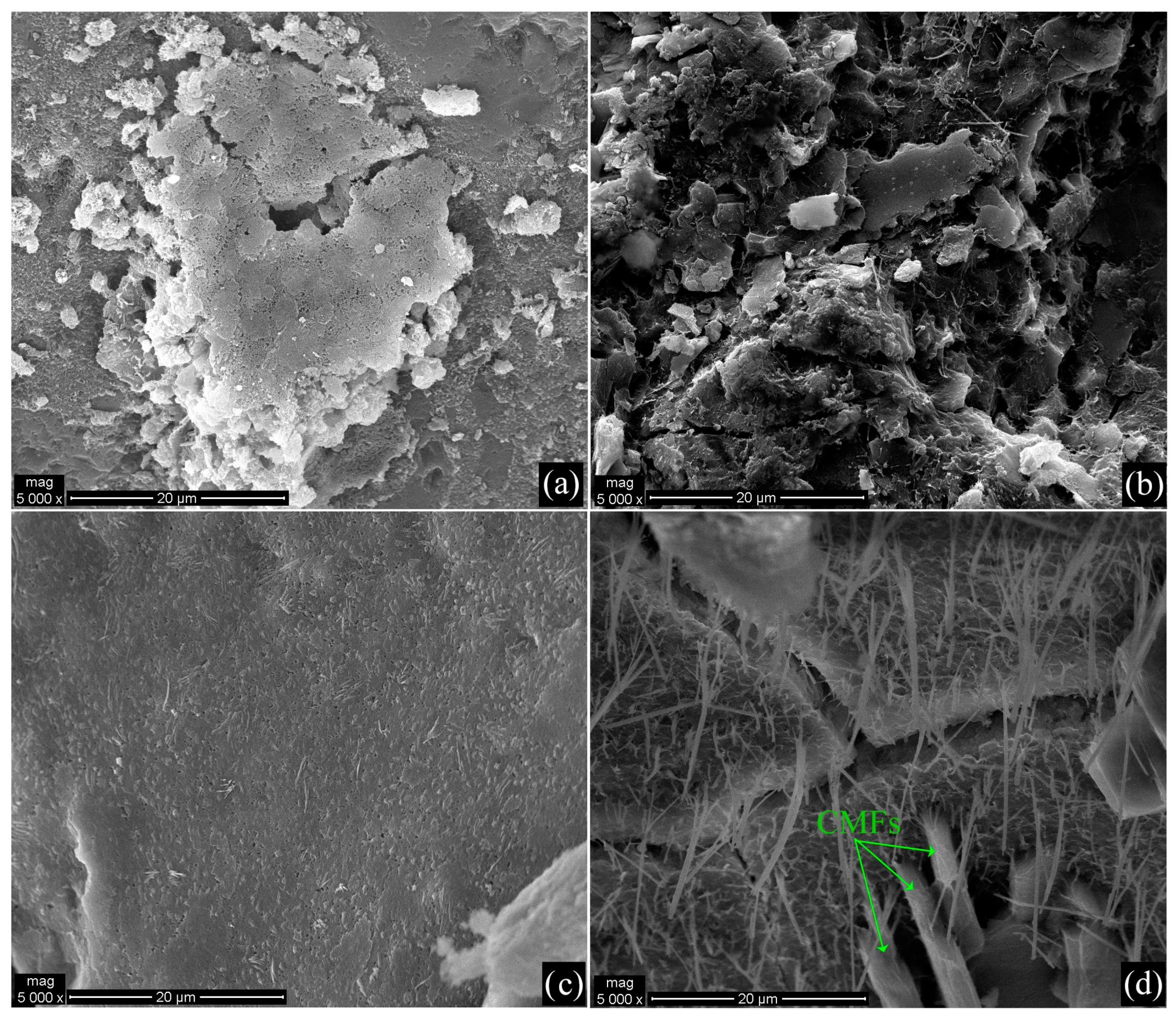
Moreover, SEM images of the mortars with incorporated CNTs and CMFs are depicted in Figure 7 and Figure 8. The SEM images illustrated in Figure 7 and Figure 8 are 20,000×-magnified and 20,000×-magnified, respectively. The presence of CMFs can only be seen in the specimen labeled Mortar-0.4%CMFs+0.1%CNTs (Figure 7d). Taking into account that the diameter of CMFs is roughly 7 μm and that the scale bars in Figure 7 and Figure 8 are 5 μm and 20 μm, respectively, it may be remarked that it is difficult to obtain representative samples including CMFs. On the other hand, the presence of CNTs is clearly observed in all the specimens including CNTs (Figure 7b–d and Figure 8b–d). Taking into consideration the aforementioned figures, it can be stated that in the sample labeled Mortar-0.4%CMFs+0.05%CNTs, the dispersion of CNTs is not as good compared to the rest of the samples. Therefore, it can be concluded that in the sample labeled Mortar-0.4%CMFs+0.05%CNTs, the CNTs are tangled and randomly distributed within the bulk mortar specimen, showing relatively poor dispersion in the cementitious matrix and random orientations. Finally, it can clearly be seen from the SEM images in Figure 7d and Figure 8d that the presence of CNTs in the sample labeled 0.4%CMFs+0.1%CNTs is higher compared to the other samples.

3.2. Mechanical Properties

The obtained values for the flexural and compressive strengths of the reference specimens, as well as the CNT-, CMF- and CNT/CMF-reinforced mortar specimens, are depicted in Figure 9, Figure 10 and Figure 11. All the specimens were evaluated after 28 days of curing in water.
Figure 9 demonstrates the flexural and compressive strength of CNT-reinforced mortar specimens. Taking into account these results, it may be noted that the highest flexural strength and compressive strength values are demonstrated for the sample with 0.05% CNTs bwoc.
Figure 10 demonstrates the flexural and compressive strength measurements of the CMF-reinforced mortar specimens. Taking into account these results, it may be noted that the incorporation of CMFs into the mortar does not enhance the flexural strength properties of the composites. However, the best flexural strength value was depicted for the sample with 0.4% CMFs bwoc. On the other hand, the incorporation of CMFs into the mortar enhances the compressive strength properties of the composites for all CMF concentrations. The sample with 0.2% CMFs bwoc demonstrated the highest compressive strength value.
Figure 11 demonstrates the flexural and compressive strength measurements of the CNT/CMF-reinforced mortar specimens. Taking into account these results, it can be seen that the incorporation of both CNTs and CMFs into the mortar influences the flexural strength of the composites. Moreover, the sample with 0.4% CMFs and 0.05% CNTs bwoc exhibits the highest flexural strength values. On the other hand, it is clear that the incorporation of both CNTs and CMFs into the mortar enhances the compressive strength of the composites. Furthermore, the sample with 0.4% CMFs and 0.05% CNTs bwoc exhibits the highest compressive strength value.
Taking into account all of the above-mentioned results, it can be seen that the incorporation of both CNTs and CMFs into the mortar influences the flexural strength of the composites. The maximum flexural strength was reported in the case of the mortar reinforced with 0.4% CMFs and 0.05% CNTs bwoc, which showed an increment of 36.57% compared to the control specimens. Another specimen that showed improved flexural strength by 30.44% compared to the reference mortar was the mortar reinforced with 0.4% CMFs and 0.02% CNTs bwoc. In the cases of the mortars reinforced with only CNTs or with only CMFs, their flexural strength was degraded compared to the reference mortar samples. In the case of mortars reinforced with only CNTs, this behavior is attributed to the poor dispersion of CNTs in the cementitious matrix. On the other hand, in the case of mortars reinforced with only CMFs, the flexural strength degradation, aside from poor CMF dispersion, is probably owed to the fact that CMFs’ short length leads to failure in load transfer [49,50]. According to the literature, the incorporation of CMFs in the cementitious matrix is expected to enhance their flexural strength, provided that their orientation is favorable and their dispersion in the matrix is homogeneous and of good quality. Otherwise, the mechanical strength of the carbon fiber-reinforced cementitious composites may not exhibit the expected results, as in the case of the flexural strength in this work. In Figure 10, the poor dispersion of CMFs in the mortars is shown since CMFs are shown to form small clusters locally. In several research articles, poor CMF dispersion has been directly correlated with CMF clustering and air bubble formation, thus altering the cementitious matrix microstructure and having a negative impact on both the mechanical and electrical properties. CMF dispersion improvement has been approached by different methodologies, including using longer mixing times, altering the order of addition for the different admixtures in the cement slurry, and using additives such as ultra-fine silicon fume, which can help in keeping CMFs apart from each other, improving their dispersion quality, as well as by practicing surface treatments on the CMFs in order to enhance their chemical and physical affinity to the cementitious matrix [15,16,18,51,52]. On the contrary, when mortars are reinforced with both CNTs and CMFs, the increment in flexural strength suggests better CNT dispersion in the cementitious matrix owed to the presence of the CMFs.
As is also indicated by these results, the compressive strength of mortars is also affected by the presence of CNTs and CMFs. Again, as in the case of the flexural strength surface treatment of CMFs, their mass fraction and, of course, their dispersion quality in the cementitious matrix play a crucial role regarding their impact on the compressive strength of the cementitious composite [51]. C. Wang et al., in their work, proved that poor dispersion of CMF in mortars can lead to a severe decrement in compressive strength, whereas when the dispersion quality is controlled via all the approaches mentioned before, the values for the compressive strength of the corresponding composites are actually improved [51]. The mortar specimens reinforced with only CMFs and CNTs/CMFs showed improved compressive strength for all CMF and CNT/CMF concentrations compared to the reference mortar specimen, even though their dispersion was poor, as discussed earlier (Figure 10 and Figure 11). This behavior is attributed to the incorporation of silica fume in the mortars. It is reported that silica fume can improve the cement microstructure by enhancing the bond between the aggregates and the cementitious paste, which is correlated with the enhancement of specific mechanical properties of the cementitious composites [53]. In the case of the mortars reinforced with CMFs and CNTs/CMFs, this mechanism prevails over the poor dispersion of the carbonaceous admixtures, and their compressive strength is enhanced. The maximum compressive strength was reported in the case of the mortar reinforced with 0.2% CMFs bwoc, which showed an increment of 88.65% compared to the control specimens. CMFs, due to their low specific surface area, do not absorb water during the mixing procedure, thus not negatively influencing the cement paste’s workability.
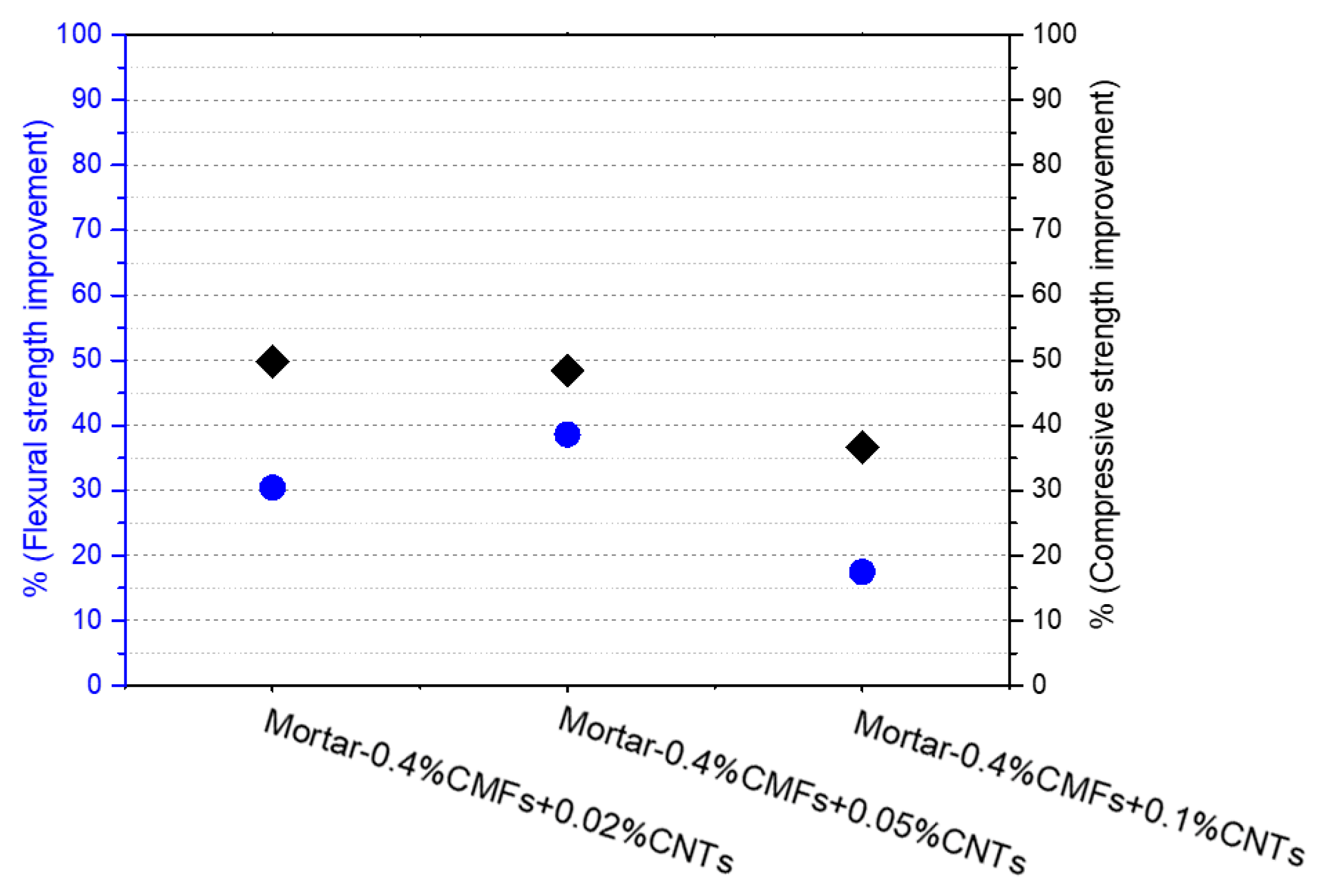
Moreover, their high flexibility prevents the fibers from interlocking, something that is common for stiff reinforcement bars such as steel bars. As a result, the CMF-reinforced mortars show improved compressive strength compared to the reference specimens. On the other hand, the mortar specimens with only CNTs incorporated in them revealed degradation in their compressive strength. This is attributed to poor CNT dispersion in the cementitious matrix, as also mentioned earlier in the evaluation of the corresponding mortars’ flexural strength. Finally, it can be noted that the maximum compressive strength was reported in the case of the mortar reinforced with 0.4% CMFs and 0.02% CNTs bwoc, which demonstrated an increment of 49.81% compared to the control specimens. Figure 12 illustrates the % improvement in the flexural and compressive strength values of the specimens labeled Mortar-0.4%CMFs+0.02%CNTs, Mortar-0.4%CMFs+0.05%CNTs and Mortar-0.4%CMFs+0.1%CNTs.
Finally, it must be mentioned that the compressive strength of the reference samples was determined to be below the expected 52.5 MPa because of the poorly controlled curing conditions and, more specifically, the low temperature and humidity during the first day of curing and the low temperature during the rest of the curing days.

3.3. Self-Sensing Capacity

Taking into account the optimum mechanical performance of the CNT/CMF-reinforced mortar composites with regard to flexural and compressive strength, the cases of Mortar-0.4%CMFs+0.02%CNTs and Mortar-0.4%CMFs+0.05%CNTs were chosen to be examined for their self-sensing capacity.
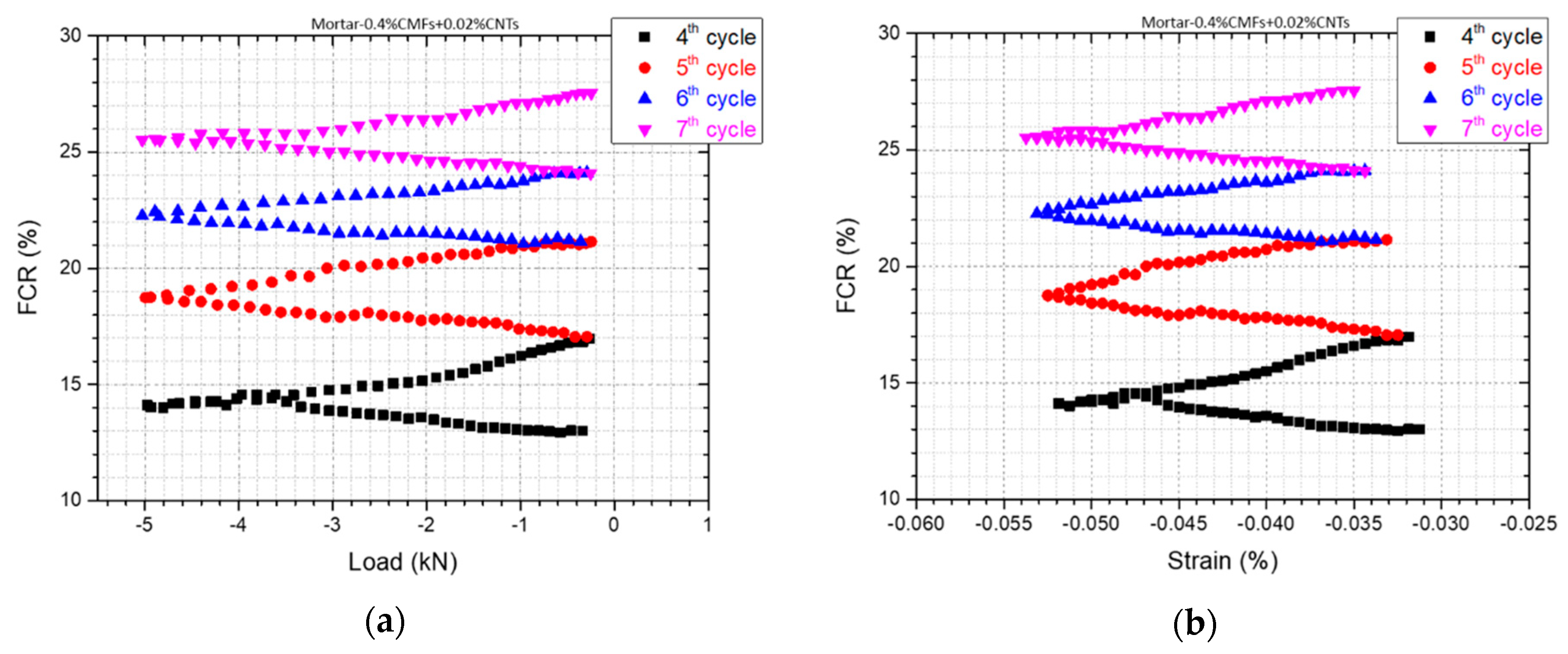
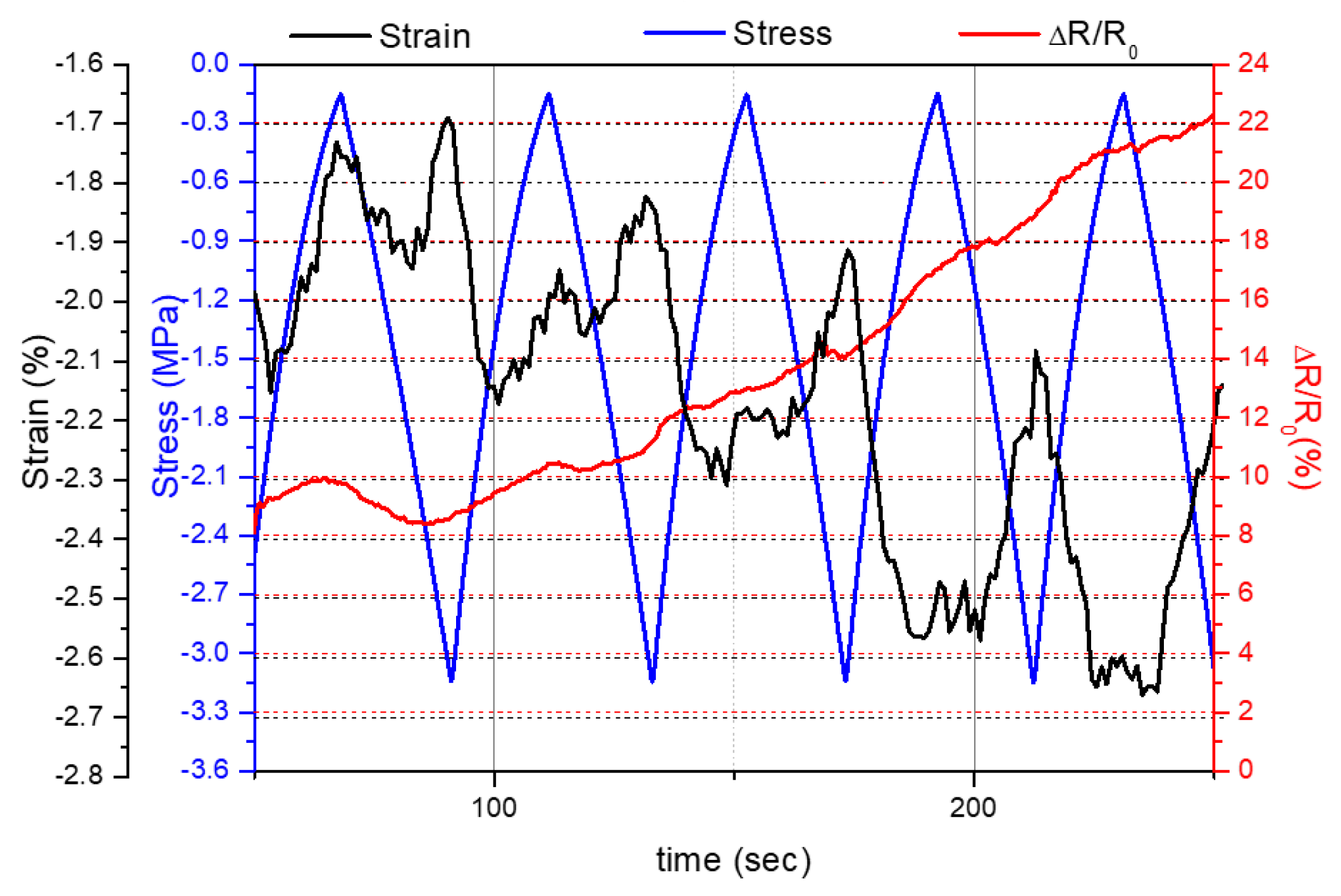
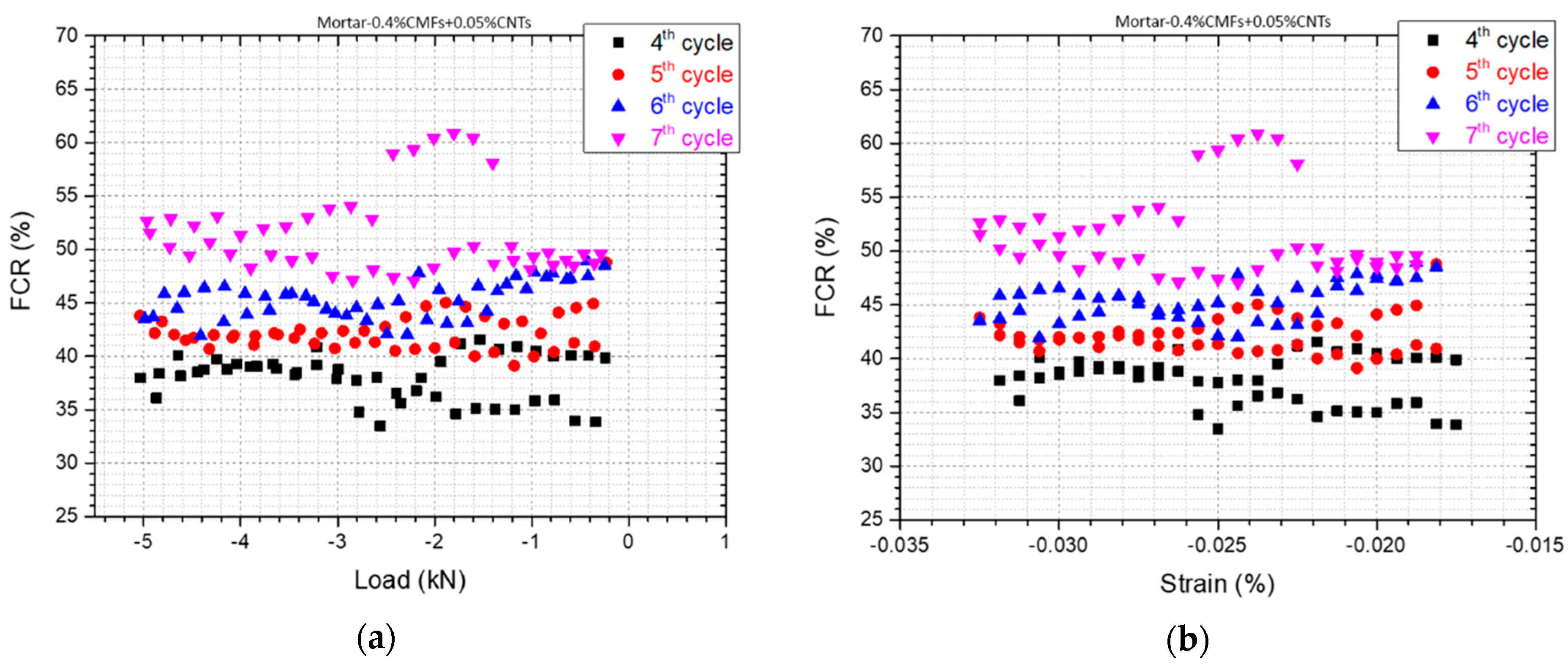
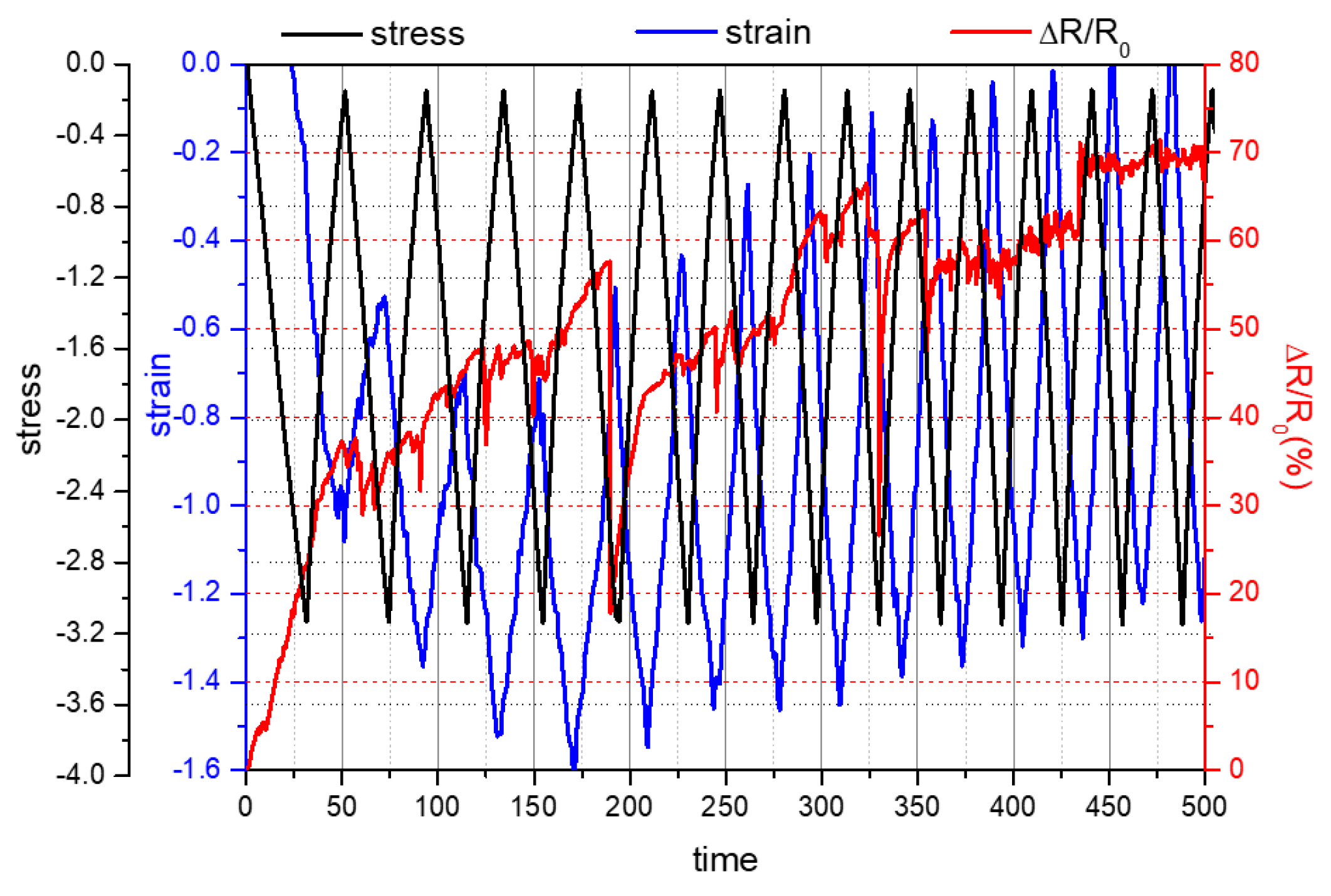
The results for the piezoresistive response of the reference mortar and the above-mentioned mortar composite specimens are illustrated in Figure 13, Figure 14, Figure 15, Figure 16, Figure 17 and Figure 18. Piezoresistivity is a means of evaluating the sensing of changes in stress and/or strain via the measurement of electrical resistance.
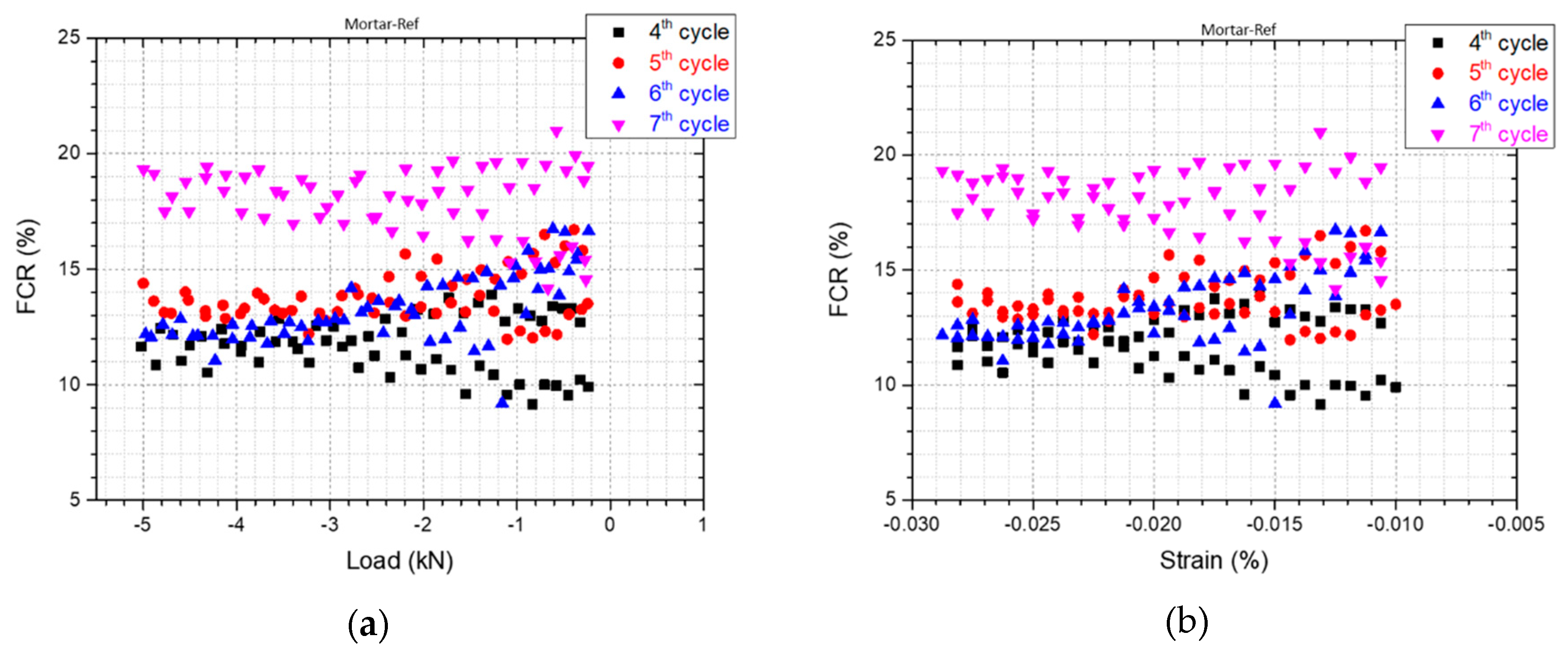
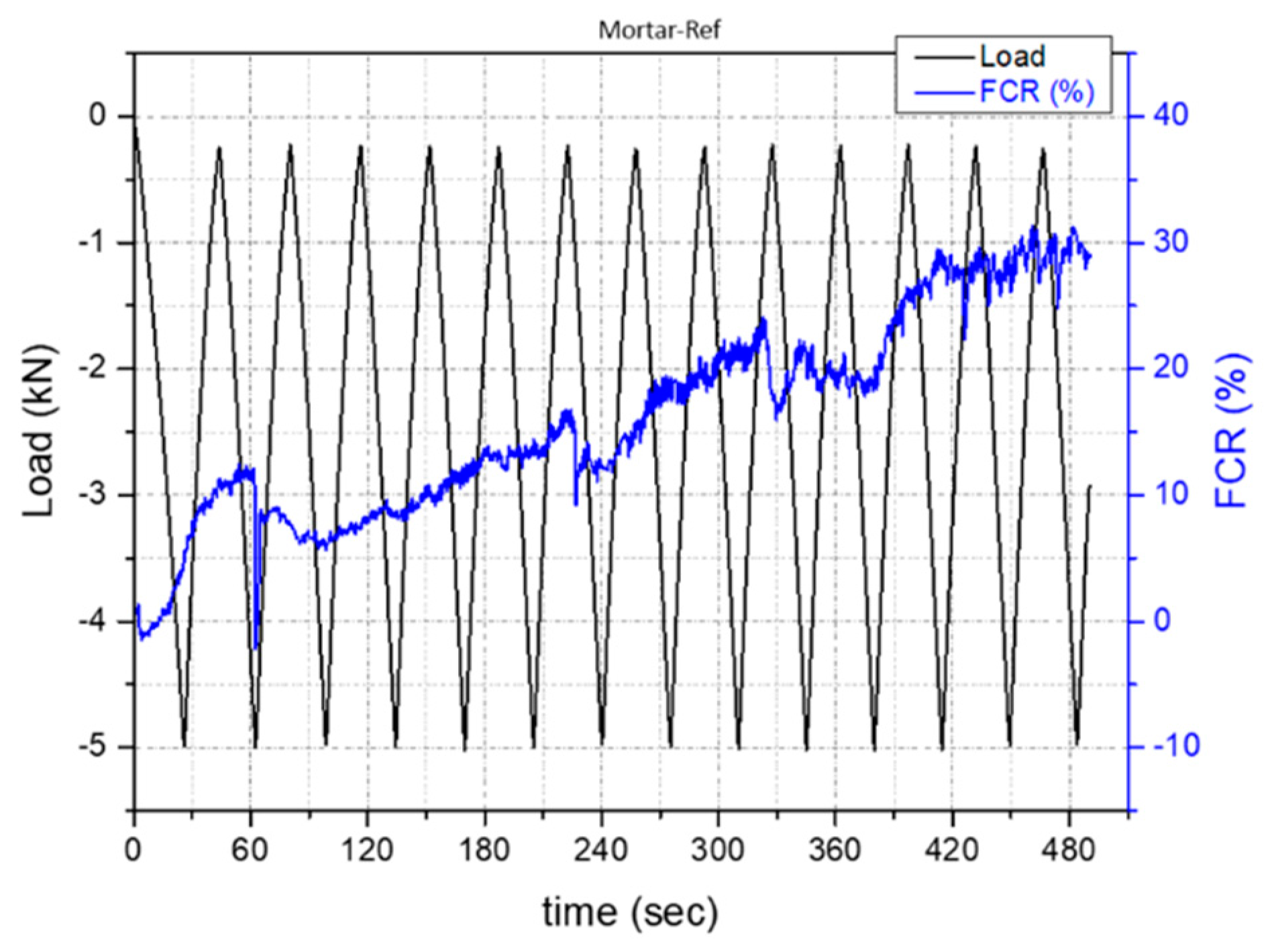
The graphs reflect the compression loading–unloading cycles and the corresponding FCR under the infliction of DC. The loading and strain are negative since the mortar specimens are compressed during the tests. It can clearly be seen from the above diagrams depicting the piezoresistivity response of the obtained specimens that the DC used causes a severe polarization effect since there is a constant increase in the resistivity/resistance over time. This phenomenon has also been thoroughly highlighted and discussed in the literature [54]. The electrical polarization caused by the movement and aggregation of ions changes the electrical conduction mechanism, which is dominated, in this case, by ionic conduction. As a result, the measured resistance is extremely increased, making it difficult to determine changes in resistance during cyclic compressive loading during DC measurement. To overcome this pitfall, the DC is applied for some time before the infliction of the compression loading. In this way, the system’s total resistance becomes stable, and the polarization effect is neutralized [4].
Moreover, it should be mentioned that the gradual increase in baseline resistance as stress cycling progressed can be attributed to irreversible damage in the mortar specimens. The increase in the amplitude of resistance variation as cycling progresses is attributed to the effect of damage on the extent of defect dynamics. The greater the damage, the greater the extent of defect healing during loading and the greater the extent of defect aggravation during unloading [55]. In the regime of elastic deformation, the damage does not affect the strain permanently, as shown by the total reversibility of the strain during cyclic loading. Nevertheless, damage occurs while the stress increases, causing a damage-induced resistance increase. The damage-induced resistance increase is a sensitive indicator of minor damage (without a change in the modulus), in addition to being a sensitive indicator of major damage (with a decrease in the modulus). In contrast, the intense and abrupt baseline resistance increase is an indicator of major damage only, which is not apparent here [55]. It should also be noted that the strain does not return to zero at the end of each cycle, denoting that the specimen is subjected to plastic deformation and subsequent crack formation.
Based on the analysis above and taking into consideration Figure 14, Figure 16 and Figure 18, the fractional change in resistivity for the reference mortar and the samples labeled Mortar-0.4%CMFs+0.02%CNTs, respectively, exhibits a steep increase, which is attributed to damages induced to the mortar specimens during loading–unloading cycles, owing to the inherent brittleness of the material. On the contrary, a smoother increase in the fractional change in resistivity as well as the fact that this change seems to be reversible upon loading (increase in stress), as depicted in the case of the samples labeled Mortar-0.4%CMFs+0.05%CNTs (Figure 18), comprise strong indications that the composites with the specific loads of CMFs and CNTs attained self-responsive behavior.
The changes in the electrical resistivity values due to the incorporation of CMFs and CNTs into mortar with silica fume before performing load tests (a pre-stress was already applied equal to 0.2 kN) are tabulated in Table 5. This table depicts how much the presence of carbonaceous material within the composite affects the electrical resistivity. The calculation of electrical resistivity was conducted taking into account that in each measurement, a fixed direct current (DC) of 1 mA was applied to the outer two electrical contacts and that the prismatic test samples were 40 mm × 40 mm × 160 mm in size. Taking into account the obtained results, it can clearly be seen that the carbonaceous material incorporation into the composites reduced the electrical resistivity prior to the load tests. However, it should be mentioned that the decrease in electrical resistivity is not inversely proportional to the increase in the presence of carbonaceous material in the composites. This outcome can be attributed to the poor dispersion of the CNTs, resulting in the creation of voids in the composites. This assumption is also confirmed by the reduction in the corresponding compressive strength values (Figure 9).
The maximum value of the GF determined during the loading–unloading cycles for the mortar composite samples (0.4%CMFs+0.02%CNTs and 0.4%CMFs+0.05%CNTs) is shown in Table 6 below. The GF was obtained from the slope of the initial, approximately linear part of the curve of resistivity versus strain in the elastic regime.
In the literature, GF values for cementitious materials are reported to be below 500 and even below 100 in cases including the incorporation of nanofillers and/or continuous fibers [49]. On the contrary, the GF values determined in this work fall under the category of “giant piezoresistivity” since they are greater than 500. This behavior is attributed to two separate mechanisms, the first one due to the incorporation of CNTs as conductive nanoparticulates and the second one due to the incorporation of CMFs, which are discontinuous fibers and, more specifically, discontinuous carbon fibers, which are also conductive. As far as the first mechanism is concerned, when compression is induced, the proximity of CNT nanoparticles is improved in the cementitious composite, thus reducing its resistivity and consequently increasing its GF value. In the case of improving the proximity of nanoparticles to the extent of creating a continuous conductive path, the reduction in the resistivity is greatly enhanced, as is the increase in the GF value, while the concentration of nanoparticles in the composite is acknowledged as the percolation threshold. As for the second mechanism, the incorporation of discontinuous carbon fibers (CMFs) tends to bridge microcracks formed in the brittle cementitious matrix. Upon applying compression to the fibers, the width of microcracks becomes smaller, thus leading to a resistivity decrease and a subsequent GF increase. On the contrary, when the compression seizes to exist, the pull-out effect is reversed, and, as a result, the composite resistivity is reduced and the GF value is increased [49,56].

4. Conclusions

Structural materials with self-sensing- and electrical actuation-related properties have attracted considerable scientific attention over the past few decades since such materials can contribute to sustainability in the construction sector and enhance safety within the lifespan of constructions. This work aims to contribute to accelerating the progress of these materials. The results obtained constitute solid groundwork in this direction. More specifically, it is shown that when CNTs and CMFs are incorporated as admixtures in mortars, the composite materials show improved mechanical strength. Different concentrations of CNTs and CMFs were evaluated, while the composites containing 0.4% bwoc CMFs together with 0.02% and 0.05% bwoc CNTs stood out as the optimum ones in terms of flexural and compressive strength. The maximum flexural strength was reported in the case of the mortar reinforced with 0.4% CMFs and 0.05% CNTs bwoc, which demonstrated an increment of 36.57% compared to the control specimens. Furthermore, the maximum compressive strength was reported in the case of the mortar reinforced with 0.4% CMFs and 0.02% CNTs bwoc, which presented an increment of 49.81% compared to the control specimens. These two cases of mortar composites, 0.4%CMFs+0.02%CNTs and 0.4%CMFs+0.05%CNTs, were then evaluated in terms of piezoresistivity, which serves as a means of evaluating the effect of strain on materials’ microstructure and electrical resistivity and whether this effect is reversible or not. Piezoresistivity renders self-sensing properties in materials. The results demonstrate that the percolation threshold of CMFs/CNTs is 0.4%CMFs+0.05%CNTs since this is the case with the highest GF value (65,696) and the FCR presents a smooth and reversible increase over time during loading and unloading cycles. As discussed previously in this work, the mechanism via which CNTs affect piezoresistivity comprises that they come closer when tension is applied, thus leading to the formation of conductive paths within the cementitious composite and a reduction in the corresponding resistivity values measured. Additionally, the mechanism that describes the effect of CMF incorporation in cementitious materials’ piezoresistivity comprises the reversible effect they have on the composite microstructure and the bridging of cracks, thus improving the formation of conductive pathways within the cementitious composite. Smart, self-sensing constructions are expected to enhance sustainability in this sector with great economic, societal, environmental and safety impacts. Further exploring materials in this direction appears promising for future work.

Author Contributions

Conceptualization, I.A.K.; methodology, I.A.K., I.K. and A.I.C.; software, I.A.K. and I.K.; validation, I.A.K. and A.I.C.; formal analysis, I.A.K. and I.K.; investigation, I.A.K. and A.I.C.; resources, I.A.K. and A.I.C.; data curation, I.A.K.; writing—original draft preparation, I.A.K. and I.A.K.; writing—review and editing, I.A.K. and C.A.C.; visualization, I.A.K. and C.A.C.; supervision, C.A.C.; project administration, C.A.C.; funding acquisition, C.A.C. All authors have read and agreed to the published version of the manuscript.

Funding

These results are part of a project that has received funding from the European Unions’ HORIZON 2020 research and innovation program under grant agreement no. 685445 (LORCENIS).

Data Availability Statement

Data is unavailable due to privacy.

Conflicts of Interest

The authors declare no conflicts of interest.

References

  1. Yang, G.; Zhao, J.; Wang, Y. Durability properties of sustainable alkali-activated cementitious materials as marine engineering material: A review. Mater. Today Sustain. 2021, 17, 100099. [Google Scholar] [CrossRef]
  2. Kanellopoulou, I.A.; Kartsonakis, I.A.; Charitidis, C.A. The Effect of Superabsorbent Polymers on the Microstructure and Self-Healing Properties of Cementitious-Based Composite Materials. Appl. Sci. 2021, 11, 700. [Google Scholar] [CrossRef]
  3. Ramezani, M.; Dehghani, A.; Sherif, M.M. Carbon nanotube reinforced cementitious composites: A comprehensive review. Constr. Build. Mater. 2022, 315, 125100. [Google Scholar] [CrossRef]
  4. Han, B.; Ding, S.; Yu, X. Intrinsic self-sensing concrete and structures: A review. Measurement 2015, 59, 110–128. [Google Scholar] [CrossRef]
  5. Ali, Z.; Yaqoob, S.; Yu, J.; D’Amore, A. Critical review on the characterization, preparation, and enhanced mechanical, thermal, and electrical properties of carbon nanotubes and their hybrid filler polymer composites for various applications. Compos. Part C Open Access 2024, 13, 100434. [Google Scholar] [CrossRef]
  6. Mittal, G.; Rhee, K.Y. Chemical vapor deposition-based grafting of CNTs onto basalt fabric and their reinforcement in epoxy-based composites. Compos. Sci. Technol. 2018, 165, 84–94. [Google Scholar] [CrossRef]
  7. Hamzaoui, R.; Bennabi, A.; Guessasma, S.; Khelifa, R.; Leklou, N. Optimal Carbon Nanotubes Concentration Incorporated in Mortar and Concrete. Adv. Mater. Res. 2012, 587, 107–110. [Google Scholar] [CrossRef]
  8. Silvestro, L.; Jean Paul Gleize, P. Effect of carbon nanotubes on compressive, flexural and tensile strengths of Portland cement-based materials: A systematic literature review. Constr. Build. Mater. 2020, 264, 120237. [Google Scholar] [CrossRef]
  9. Abu Al-Rub, R.K.; Tyson, B.M.; Yazdanbakhsh, A.; Grasley, Z. Mechanical Properties of Nanocomposite Cement Incorporating Surface-Treated and Untreated Carbon Nanotubes and Carbon Nanofibers. J. Nanomech. Micromech. 2012, 2, 1–6. [Google Scholar] [CrossRef]
  10. Evangelista, A.C.J.; de Morais, J.F.; Tam, V.; Soomro, M.; Torres Di Gregorio, L.; Haddad, A.N. Evaluation of Carbon Nanotube Incorporation in Cementitious Composite Materials. Materials 2019, 12, 1504. [Google Scholar] [CrossRef]
  11. Li, X.; Rafieepour, S.; Miska, S.Z.; Takach, N.E.; Ozbayoglu, E.; Yu, M.; Mata, C. Carbon nanotubes reinforced lightweight cement testing under tri-axial loading conditions. J. Pet. Sci. Eng. 2019, 174, 663–675. [Google Scholar] [CrossRef]
  12. Chen, S.J.; Collins, F.G.; Macleod, A.J.N.; Pan, Z.; Duan, W.H.; Wang, C.M. Carbon nanotube–cement composites: A retrospect. IES J. Part A Civ. Struct. Eng. 2011, 4, 254–265. [Google Scholar] [CrossRef]
  13. de Souza, T.C.; Pinto, G.; Cruz, V.S.; Moura, M.; Ladeira, L.O.; Calixto, J.M. Evaluation of the rheological behavior, hydration process, and mechanical strength of Portland cement pastes produced with carbon nanotubes synthesized directly on clinker. Constr. Build. Mater. 2020, 248, 118686. [Google Scholar] [CrossRef]
  14. Jung, M.; Lee, Y.-s.; Hong, S.-G.; Moon, J. Carbon nanotubes (CNTs) in ultra-high performance concrete (UHPC): Dispersion, mechanical properties, and electromagnetic interference (EMI) shielding effectiveness (SE). Cem. Concr. Res. 2020, 131, 106017. [Google Scholar] [CrossRef]
  15. Gao, J.; Sha, A.; Wang, Z.; Hu, L.; Yun, D.; Liu, Z.; Huang, Y. Characterization of carbon fiber distribution in cement-based composites by Computed Tomography. Constr. Build. Mater. 2018, 177, 134–147. [Google Scholar] [CrossRef]
  16. Chuang, W.; Geng-sheng, J.; Bing-liang, L.; Lei, P.; Ying, F.; Ni, G.; Ke-zhi, L. Dispersion of carbon fibers and conductivity of carbon fiber-reinforced cement-based composites. Ceram. Int. 2017, 43, 15122–15132. [Google Scholar] [CrossRef]
  17. Díaz, B.; Guitián, B.; Nóvoa, X.R.; Pérez, C. Analysis of the microstructure of carbon fibre reinforced cement pastes by impedance spectroscopy. Constr. Build. Mater. 2020, 243, 118207. [Google Scholar] [CrossRef]
  18. Tong, Z.; Guo, H.; Gao, J.; Wang, Z. A novel method for multi-scale carbon fiber distribution characterization in cement-based composites. Constr. Build. Mater. 2019, 218, 40–52. [Google Scholar] [CrossRef]
  19. Kim, G.M.; Park, S.M.; Ryu, G.U.; Lee, H.K. Electrical characteristics of hierarchical conductive pathways in cementitious composites incorporating CNT and carbon fiber. Cem. Concr. Compos. 2017, 82, 165–175. [Google Scholar] [CrossRef]
  20. Yoon, H.N.; Jang, D.; Lee, H.K.; Nam, I.W. Influence of carbon fiber additions on the electromagnetic wave shielding characteristics of CNT-cement composites. Constr. Build. Mater. 2021, 269, 121238. [Google Scholar] [CrossRef]
  21. Ijaz, H.; Mahmood, A.; Abdel-Daim, M.M.; Sarfraz, R.M.; Zaman, M.; Zafar, N.; Alshehery, S.; Salem-Bekhit, M.M.; Ali, M.A.; Eltayeb, L.B.; et al. Review on carbon nanotubes (CNTs) and their chemical and physical characteristics, with particular emphasis on potential applications in biomedicine. Inorg. Chem. Commun. 2023, 155, 111020. [Google Scholar] [CrossRef]
  22. Gamboa, A.; Fernandes, E.C. Resistive hydrogen sensors based on carbon nanotubes: A review. Sens. Actuators A Phys. 2024, 366, 115013. [Google Scholar] [CrossRef]
  23. Tundwal, A.; Kumar, H.; Binoj, B.J.; Sharma, R.; Kumari, R.; Yadav, A.; Kumar, G.; Dhayal, A.; Yadav, A.; Singh, D.; et al. Conducting polymers and carbon nanotubes in the field of environmental remediation: Sustainable developments. Coord. Chem. Rev. 2024, 500, 215533. [Google Scholar] [CrossRef]
  24. Dipta, I.K.R.A.; Lee, C.W. Recent advances and perspectives in carbon nanotube production from the electrochemical conversion of carbon dioxide. J. CO2 Util. 2024, 82, 102745. [Google Scholar] [CrossRef]
  25. Fang, Y.; Wang, J.; Ma, H.; Wang, L.; Qian, X.; Qiao, P. Performance enhancement of silica fume blended mortars using bio-functionalized nano-silica. Constr. Build. Mater. 2021, 312, 125467. [Google Scholar] [CrossRef]
  26. Chen, H.; Chen, Q.; Xu, Y.; Lawi, A.S. Effects of silica fume and Fly ash on properties of mortar reinforced with recycled-polypropylene. Constr. Build. Mater. 2022, 316, 125887. [Google Scholar] [CrossRef]
  27. Song, C.; Hong, G.; Choi, S. Effect of dispersibility of carbon nanotubes by silica fume on material properties of cement mortars: Hydration, pore structure, mechanical properties, self-desiccation, and autogenous shrinkage. Constr. Build. Mater. 2020, 265, 120318. [Google Scholar] [CrossRef]
  28. Kim, G.M.; Nam, I.W.; Yang, B.; Yoon, H.N.; Lee, H.K.; Park, S. Carbon nanotube (CNT) incorporated cementitious composites for functional construction materials: The state of the art. Compos. Struct. 2019, 227, 111244. [Google Scholar] [CrossRef]
  29. Kim, H.K.; Nam, I.W.; Lee, H.K. Enhanced effect of carbon nanotube on mechanical and electrical properties of cement composites by incorporation of silica fume. Compos. Struct. 2014, 107, 60–69. [Google Scholar] [CrossRef]
  30. Stynoski, P.; Mondal, P.; Marsh, C. Effects of silica additives on fracture properties of carbon nanotube and carbon fiber reinforced Portland cement mortar. Cem. Concr. Compos. 2015, 55, 232–240. [Google Scholar] [CrossRef]
  31. Lee, S.J.; You, I.; Zi, G.; Yoo, D.Y. Experimental Investigation of the Piezoresistive Properties of Cement Composites with Hybrid Carbon Fibers and Nanotubes. Sensors 2017, 17, 2516. [Google Scholar] [CrossRef] [PubMed]
  32. Garg, M.; Das, C.S.; Gupta, R. Use of silica particles to improve dispersion of -COOH CNTs/carbon fibers to produce HyFRCC. Constr. Build. Mater. 2020, 250, 118777. [Google Scholar] [CrossRef]
  33. Kim, G.M.; Yoon, H.N.; Lee, H.K. Autogenous shrinkage and electrical characteristics of cement pastes and mortars with carbon nanotube and carbon fiber. Constr. Build. Mater. 2018, 177, 428–435. [Google Scholar] [CrossRef]
  34. Zhan, M.; Pan, G.; Zhou, F.; Mi, R.; Shah, S.P. In situ-grown carbon nanotubes enhanced cement-based materials with multifunctionality. Cem. Concr. Compos. 2020, 108, 103518. [Google Scholar] [CrossRef]
  35. Zhou, Z.; Xie, N.; Cheng, X.; Feng, L.; Hou, P.; Huang, S.; Zhou, Z. Electrical properties of low dosage carbon nanofiber/cement composite: Percolation behavior and polarization effect. Cem. Concr. Compos. 2020, 109, 103539. [Google Scholar] [CrossRef]
  36. Ding, S.; Ruan, Y.; Yu, X.; Han, B.; Ni, Y.-Q. Self-monitoring of smart concrete column incorporating CNT/NCB composite fillers modified cementitious sensors. Constr. Build. Mater. 2019, 201, 127–137. [Google Scholar] [CrossRef]
  37. Collins, F.; Lambert, J.; Duan, W.H. The influences of admixtures on the dispersion, workability, and strength of carbon nanotube–OPC paste mixtures. Cem. Concr. Compos. 2012, 34, 201–207. [Google Scholar] [CrossRef]
  38. Punetha, V.D.; Rana, S.; Yoo, H.J.; Chaurasia, A.; McLeskey, J.T.; Ramasamy, M.S.; Sahoo, N.G.; Cho, J.W. Functionalization of carbon nanomaterials for advanced polymer nanocomposites: A comparison study between CNT and graphene. Prog. Polym. Sci. 2017, 67, 1–47. [Google Scholar] [CrossRef]
  39. Dubey, R.; Dutta, D.; Sarkar, A.; Chattopadhyay, P. Functionalized carbon nanotubes: Synthesis, properties and applications in water purification, drug delivery, and material and biomedical sciences. Nanoscale Adv. 2021, 3, 5722–5744. [Google Scholar] [CrossRef]
  40. Lavagna, L.; Nisticò, R.; Musso, S.; Pavese, M. Functionalization as a way to enhance dispersion of carbon nanotubes in matrices: A review. Mater. Today Chem. 2021, 20, 100477. [Google Scholar] [CrossRef]
  41. Meskher, H.; Ghernaout, D.; Thakur, A.K.; Jazi, F.S.; Alsalhy, Q.F.; Christopher, S.S.; Sathyamurhty, R.; Saidur, R. Prospects of functionalized carbon nanotubes for supercapacitors applications. Mater. Today Commun. 2024, 38, 108517. [Google Scholar] [CrossRef]
  42. EN 196-1:2016; Methods of Testing Cement—Part 1: Determination of Strength. European Committee for Standardization: Brussels, Belgium, 2016.
  43. Goulis, P.; Kartsonakis, I.A.; Mpalias, K.; Charitidis, C. Combined effects of multi-walled carbon nanotubes and lignin on polymer fiber-reinforced epoxy composites. Mater. Chem. Phys. 2018, 218, 18–27. [Google Scholar] [CrossRef]
  44. Trompeta, A.-F.A.; Koumoulos, E.P.; Kartsonakis, I.A.; Charitidis, C.A. Advanced characterization of by-product carbon film obtained by thermal chemical vapor deposition during CNT manufacturing. Manuf. Rev. 2017, 4, 7. [Google Scholar] [CrossRef]
  45. Environmental Product Declarartion for Portland Cement C, CEM I 42.5R & CEM I 52.5N, Programme: The International EPD® System; EPD registration number: S-P-03612; Valid until: 2026-06-02; EPD International AB: Stockholm, Sweden, 2021.
  46. Luo, T.; Hua, C.; Sun, Q.; Tang, L.; Yi, Y.; Pan, X. Early-Age Hydration Reaction and Strength Formation Mechanism of Solid Waste Silica Fume Modified Concrete. Molecules 2021, 26, 5663. [Google Scholar] [CrossRef]
  47. Kanellopoulou, I.; Karaxi, E.K.; Karatza, A.; Kartsonakis, I.A.; Charitidis, C.A. Effect of submicron admixtures on mechanical and self-healing properties of cement-based composites. Fatigue Fract. Eng. Mater. Struct. 2019, 42, 1494–1509. [Google Scholar] [CrossRef]
  48. Chung, D.L.D. Functional Materials: Electrical, Dielectric, Electromagnetic, Optical and Magnetic Applications (Engineering Materials for Technological Needs); World Scientific: Singapore; Hackensack, NJ, USA, 2010. [Google Scholar]
  49. Chung, D.D.L. A critical review of piezoresistivity and its application in electrical-resistance-based strain sensing. J. Mater. Sci. 2020, 55, 15367–15396. [Google Scholar] [CrossRef]
  50. Cwirzen, A.; Habermehl-Cwirzen, K. The Effect of Carbon Nano- and Microfibers on Strength and Residual Cumulative Strain of Mortars Subjected to Freeze-Thaw Cycles. J. Adv. Concr. Technol. 2013, 11, 80–88. [Google Scholar] [CrossRef]
  51. Wang, C.; Li, K.-Z.; Li, H.-J.; Jiao, G.-S.; Lu, J.; Hou, D.-S. Effect of carbon fiber dispersion on the mechanical properties of carbon fiber-reinforced cement-based composites. Mater. Sci. Eng. A 2008, 487, 52–57. [Google Scholar] [CrossRef]
  52. Lu, Z.; Hanif, A.; Sun, G.; Liang, R.; Parthasarathy, P.; Li, Z. Highly dispersed graphene oxide electrodeposited carbon fiber reinforced cement-based materials with enhanced mechanical properties. Cem. Concr. Compos. 2018, 87, 220–228. [Google Scholar] [CrossRef]
  53. Badalyan, M.M.; Muradyan, N.G.; Shainova, R.S.; Arzumanyan, A.A.; Kalantaryan, M.A.; Sukiasyan, R.R.; Yeranosyan, M.; Laroze, D.; Vardanyan, Y.V.; Barseghyan, M.G. Effect of Silica Fume Concentration and Water–Cement Ratio on the Compressive Strength of Cement-Based Mortars. Buildings 2024, 14, 757. [Google Scholar] [CrossRef]
  54. Han, B.; Yu, X.; Ou, J. Measurement of Sensing Signal of Self-Sensing Concrete. In Self-Sensing Concrete in Smart Structures; Butterworth-Heinemann: Oxford, UK, 2014; pp. 67–93. [Google Scholar] [CrossRef]
  55. Chung, D. Damage in cement-based materials, studied by electrical resistance measurement. Mater. Sci. Eng. R Rep. 2003, 42, 1–40. [Google Scholar] [CrossRef]
  56. Dang, N.; Tao, J.; Zeng, Q.; Zhao, W. May the Piezoresistivity of GNP-Modified Cement Mortar Be Related to Its Fractal Structure? Fractal Fract. 2021, 5, 148. [Google Scholar] [CrossRef]
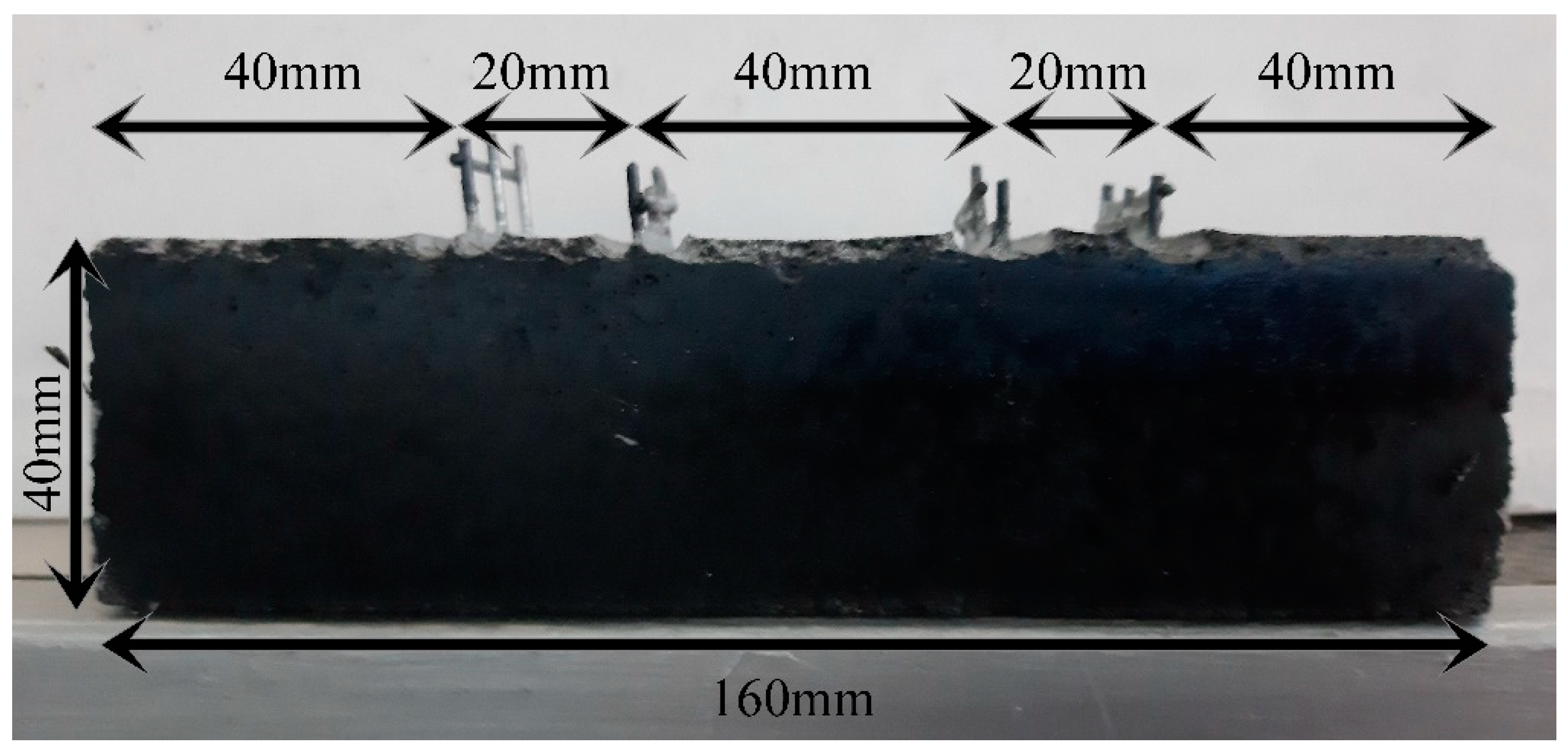
Figure 1. Indicative photo of prismatic test samples 40 mm × 40 mm × 160 mm in size with electrodes embedded into them.
Fibers 12 00062 g001
Figure 2. Schematic representation of the synthetic process for the fabrication of prismatic test samples: 40 mm × 40 mm × 160 mm in size.
Fibers 12 00062 g002
Figure 3. Flexural strength measurements.
Fibers 12 00062 g003
Figure 4. Compressive strength measurements.
Fibers 12 00062 g004
Figure 5. Indicative photo of the experimental setup for measuring the electrical resistance under the compressive load of the prismatic test samples, which are 40 mm × 40 mm × 160 mm in size.
Fibers 12 00062 g005
Figure 6. SEM images of (a) the produced MWCNTs (×300,000); (b) the utilized CMFs (×5000).
Fibers 12 00062 g006
Figure 7. The SEM images, 20,000×-magnified, of (a) Mortar-Reference; (b) Mortar-0.4%CMFs+0.02%CNTs; (c) Mortar-0.4%CMFs+0.05%CNTs; (d) Mortar-0.4%CMFs+0.1%CNTs.
Fibers 12 00062 g007
Figure 8. The SEM images, 5,000x-magnified, of (a) Mortar-Reference; (b) Mortar-0.4%CMFs+0.02%CNTs; (c) Mortar-0.4%CMFs+0.05%CNTs; (d) Mortar-0.4%CMFs+0.1%CNTs.
Fibers 12 00062 g008
Figure 9. The flexural strength and compressive strength of CNT-reinforced mortar specimens.
Fibers 12 00062 g009
Figure 10. The flexural strength and compressive strength of CMF-reinforced mortar specimens.
Fibers 12 00062 g010
Figure 11. The flexural strength and compressive strength of CNT/CMF-reinforced mortar specimens.
Fibers 12 00062 g011
Figure 12. The % improvement in the flexural () and compressive (♦) strength of the mortar specimens.
Fibers 12 00062 g012
Figure 13. Fractional change in resistivity vs. (a) inflicted load and (b) inflicted strain for mortar reference specimens.
Fibers 12 00062 g013
Figure 14. Fractional changes in resistivity for mortar reference specimens.
Fibers 12 00062 g014
Figure 15. Fractional change in resistivity vs. (a) inflicted load and (b) inflicted strain for specimens labeled Mortar-0.4%CMFs+0.02%CNTs.
Fibers 12 00062 g015
Figure 16. Fractional changes in resistivity for specimens labeledMortar-0.4%CMFs+0.02%CNTs.
Fibers 12 00062 g016
Figure 17. Fractional change in resistivity vs. (a) inflicted load and (b) inflicted strain for specimens labeled Mortar-0.4%CMFs+0.05%CNTs.
Fibers 12 00062 g017
Figure 18. Fractional changes in resistivity for specimens labeled Mortar-0.4%CMFs+0.05%CNTs.
Fibers 12 00062 g018
Table 1. Chemical compositions and physical properties of cementitious materials *, **.
CompositionSiO2Al2O3Fe2O3CaOMgOSO3Na2OK2O
% (mass) cement19.474.753.4363.161.432.680.280.62
* Loss on Ignition: 3.26. ** Specific surface area (cm2/g): 3635.
Table 2. Tabulated parameters for the fabrication of CNT-reinforced mortar specimens using silica fume.
SamplesCement (g)Silica Fume (g)Sand (g)Ratio w/cH2O (mL)Concentration CNTs
(% bwoc)
Sika®Stabilizer-100
(g)
Mortar-Ref4054513500.5225--
Mortar-0.02%CNT4054513500.52250.020.25
Mortar-0.05%CNT4054513500.52250.050.625
Mortar-0.1%CNT4054513500.73150.11.25
Mortar-0.2%CNT4054513500.73150.22.5
Mortar-0.5%CNT4054513500.73150.56.25
Table 3. Tabulated parameters for the fabrication of CMF-reinforced mortar specimens using silica fume.
SamplesCement (g)Silica Fume (g)Sand (g)Ratio w/cH2O (mL)Concentration CMFs (%bwoc)Sika®Stabilizer-100 (g)
Mortar-Ref4054513500.5225--
Mortar-0.05%CMF4054513500.52250.050.405
Mortar-0.2%CMF4054513500.52250.20.405
Mortar-0.25%CMF4054513500.73150.250.405
Mortar-0.3%CMF4054513500.73150.30.405
Mortar-0.4%CMF4054513500.73150.40.405
Mortar-1%CMF4054513500.731510.405
Table 4. Tabulated parameters for the fabrication of CNT/CMF-reinforced mortar specimens. For each sample, 405 g of cement, 45 g of silica fume and 1350 g of sand were used, respectively.
SamplesRatio w/cH2O (mL)Concentration CNTs
(%bwoc)
Concentration CMFs
(%bwoc)
Sika®Stabilizer-100
(g)
Mortar-Ref0.5225---
Mortar-0.4%CMFs+0.02%CNTs0.52250.020.040.225
Mortar-0.4%CMFs+0.05%CNTs0.52250.050.040.562
Mortar-0.4%CMFs+0.1%CNTs0.52250.10.041.125
Table 5. Electrical resistivity values prior to load tests.
Electrical Resistivity (Ohm m)
Mortar-Ref531.1
Mortar-0.4%CMFs+0.02%CNTs254.3
Mortar-0.4%CMFs+0.05%CNTs462.9
Table 6. Maximum GF for self-sensing additive content.
CMFs + CNTs (%)GF (Maximum)
0.4 + 0.02182
0.4 + 0.0565,696
Disclaimer/Publisher’s Note: The statements, opinions and data contained in all publications are solely those of the individual author(s) and contributor(s) and not of MDPI and/or the editor(s). MDPI and/or the editor(s) disclaim responsibility for any injury to people or property resulting from any ideas, methods, instructions or products referred to in the content.