Article

Coaxial Electrospinning of PCL-PVA Membranes Loaded with N-Heterocyclic Gold Complex for Antitumoral Applications

by
Raffaele Longo
1,*,
Luigi Vertuccio
2,
Francesca Aliberti
1,
Annaluisa Mariconda
3,
Marialuigia Raimondo
1,
Pasquale Longo
4 and
Liberata Guadagno
1,*
1
Department of Industrial Engineering, University of Salerno, Via Giovanni Paolo II, 132, 84084 Fisciano, Italy
2
Department of Engineering, University of Campania “Luigi Vanvitelli”, Via Roma 29, 813031 Aversa, Italy
3
Department of Basic and Applied Sciences, University of Basilicata, Via Dell’Ateneo Lucano 10, 85100 Potenza, Italy
4
Department of Chemistry and Biology, University of Salerno, Via Giovanni Paolo II, 132, 84084 Fisciano, Italy
*
Authors to whom correspondence should be addressed.
Fibers 2024, 12(12), 101; https://doi.org/10.3390/fib12120101
Submission received: 4 October 2024 / Revised: 2 November 2024 / Accepted: 19 November 2024 / Published: 21 November 2024

Highlights

  • Coaxial electrospun membranes containing an antitumoral active agent were developed.
  • The synthetic antitumoral agent was chosen due to its effective activity against melanoma.
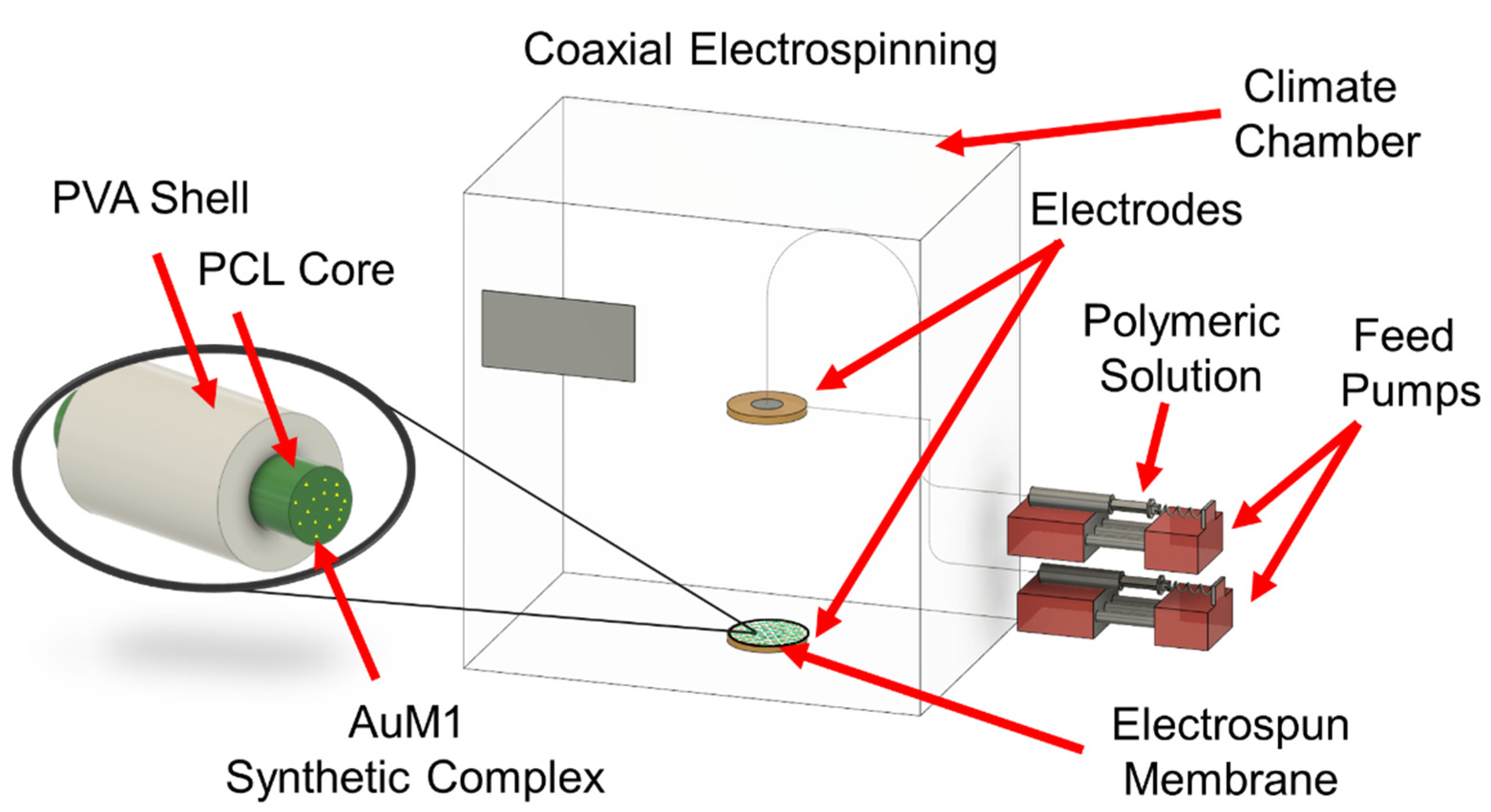
  • The antitumoral complex was loaded inside the core section of the coaxial fibers.
  • The control of the parameters and modality of the electrospinning process facilitates tailoring of the release of the antitumoral agent.

Abstract

:
Coaxial electrospun membranes made of polycaprolactone (PCL) and polyvinylalcohol (PVA) were produced and filled with a promising synthetic gold complex (AuM1) for antitumoral applications. Coaxial nanofibers characterized by a PVA shell and PCL + AuM1 core were made to design a multi-step release in a physiological environment. The coaxial structure can sensitively limit the burst effect, allowing the release of 90% of the active substance AuM1 in about three days. By comparison, the PCL membrane loaded with AuM1 produced via uniaxial electrospinning releases 90% of the drug in about 1 h. The correlation of release kinetic data with the morphological evolution and the spectroscopic investigation highlighted how coaxial electrospinning is a promising process for designing drug delivery systems to control the release of active substances over time. The proper design of core–shell systems could be of great interest for prolonged therapies, such as antitumoral therapy.

1. Introduction

The research on drug delivery devices mainly focuses on two directions: the development of stimuli-responsive devices [1,2] and the design of biocompatible, biomimetic devices with slow drug release kinetics that can be applied for antibacterial [3,4], antiviral [5], or antitumoral applications [6,7,8,9].
The possibility of designing functional biomaterials that can provide topical treatments to patients with oncological diseases would be a significant step forward because this route of administration can sensitively decrease side effects [10] or patient resistance to the therapy [11].
In this scenario, the electrospinning process allows great attention to be paid to developing topical drug delivery systems, allowing the easy loading of substances and nanoparticles [12] inside the polymeric matrices [13] to mimic human tissue in controlling drug delivery.
In these nanofibrous systems, drug release can be sustained for up to about three days, and this result is mainly achieved by favoring the diffusive mechanism [14], having stimuli-responsive systems [15], and, indeed, correctly selecting the matrix–filler system [6].
However, further studies have also deeply analyzed the potentialities of the coaxial electrospinning process [16]. This process allows for obtaining bilayer nanofibers, making it possible to tune the drug release kinetics [17,18] properly.
The obtained bilayer nanofibers can be made of two polymers with different functions. For example, the shell can increase biocompatibility/wettability [19], whereas the core enhances mechanical performance and durability in the physiological environment [20].
The drug release slows when the active substance is loaded in the core, obtaining a multi-step release process through a single biomedical device. Coaxial electrospinning allows for the meshing of the characteristics of hydrophilic (such as PVA, gelatin, etc.) and hydrophobic (such as PCL, PLA, and so on) biopolymers, combining the desired properties of the two different polymers. For example, hydrophilic biopolymers generally guarantee a better adhesion of the medical device to the human tissue [21], whereas hydrophobic biopolymers are usually preferable to maintain their structure over time during the application [22].
In recent studies, research articles conducted by Guadagno et al. [6,7] proved that it is possible to tailor the release kinetic of active agents from electrospun nanofibers by properly varying the chemical interaction between active fillers and hosting matrices.
The current research paper analyses the possibility of modifying the release profile of an antitumoral electrospun membrane by exploiting the potentialities of the coaxial electrospinning process.
Different types of antitumoral agents are now designed [23,24], and several active agents have been successfully used in electrospun membranes (e.g., 5-fluorouracil [25], Paclitaxel [26], Doxorubicin [27]). However, it is undoubtedly of great interest to test new promising active molecules, proposing completely innovative systems. For this purpose, the organometallic complex AuM1 was selected. This gold-based complex is stabilized by an N-heterocyclic carbene ligand asymmetrically substituted on the nitrogen atoms. AuM1 demonstrated significant antiproliferative activity against several cancer cell lines (e.g., MCF-7 and MDA-MB-231) [28]. Generally, metal complexes exert their effects by inducing oxidative stress and causing DNA lesions, which lead to apoptosis and cell death [29].
Nevertheless, a relevant number of parameters must be handled to obtain membranes properly through coaxial electrospinning. For this reason, it is still necessary to study the process to understand its potential fully.
In this research work, coaxial electrospun membranes made of PVA (shell) and PCL loaded with the synthetic agent AuM1 (core), which is active against melanoma tumoral cells, are produced. The bilayer nanofibrous structure allows the tuning of the release kinetic, the evolution of which was analyzed over time from the morphological and chemical points of view.

2. Materials and Methods

2.1. Materials

The materials used in the current study are reported in Table 1.

2.2. AuM1 Synthesis and Characterization

AuM1 was synthesized through 4 reaction steps, reported in Figure 1 [30]. The first two steps led to forming the imidazolium salt S1 in its racemic form (Steps 1 and 2). The nitrogen atoms were asymmetrically alkylated with 2-hydroxy-2-phenylethyl and methyl group, respectively. The gold complex was obtained by first synthesizing the silver complex (Step 3), followed by transmetalation (Step 4), which is a simple method for synthesizing gold-based metal complexes that avoid using strong bases. All synthesized compounds were characterized by NMR and mass spectral studies, and the results are reported in the section “Supplementary Materials”. The characterizations performed are consistent with the data reported in the literature [30].

2.3. Coaxial Electrospinning Process

The nanofibrous membranes were obtained using EC-CLI electrospinning equipment purchased from IME Technologies (Spaarpot 147, 5667 KV, Geldrop, The Netherlands). An injector diameter of 0.8 mm was used for uniaxial electrospinning, whereas for the coaxial shell injector, the diameter was 1.2 mm. The climate chamber was set at 25 °C and 35% relative humidity. The schematization of the coaxial electrospinning process is reported in Figure 2. PCL with 1%AuM1 in HFIP was used as a core polymeric solution, whereas PVA in HFIP was used as the shell polymeric solution.
Uniaxial electrospun membranes of PCL and PVA alone were also produced for comparison.
Electrospinning is a process that requires the management of different parameters: solution parameters (type of solvent, type of polymer, polymer concentration, dielectric constant, viscosity, etc.), processing parameters (flow rate, injector–collector distance, and applied potential difference), and environmental parameters (temperature and relative humidity) [31,32]. By appropriately varying these different parameters, it is possible to obtain nanofibers with different characteristics, dimensions, etc. [33]. In this case, process parameters have been optimized to reach a steady state condition in which the electrospinning process was stable for several hours, obtaining a homogeneous membrane with a thickness of hundreds of microns.
Generally, by using a higher flow rate, it is necessary to increase the intensity of the electric field, reduce the injector–collector distance, or apply higher potential differences [34,35]. Similarly, in the case of coaxial electrospinning, where there are two polymeric solutions to electrospin parallelly, the total flow rate increases, so it may be necessary to apply higher potential differences.
Table 2 reports the process parameters for producing PVA (alone), PCL (alone), and a coaxial membrane loaded with 1%AuM1.
Given the fact that the cytotoxic activity against melanoma cell lines has been proven to be extremely high, at between 5 and 10 μM [7], 1%AuM1-loaded membranes were considered suitable to obtain nanofibrous membranes that could be effective against melanoma cell lines, considering that the biomedical tests generally require a membrane with a mass of around 1 mg and a volume of culture of 1 mL. Moreover, similar percentages of AuM1 have been adopted in previous group research papers, confirming good antitumoral activities [6,7].

2.4. Production and Characterization of the Material

The methods used in the current study are reported in Table 3.

3. Results

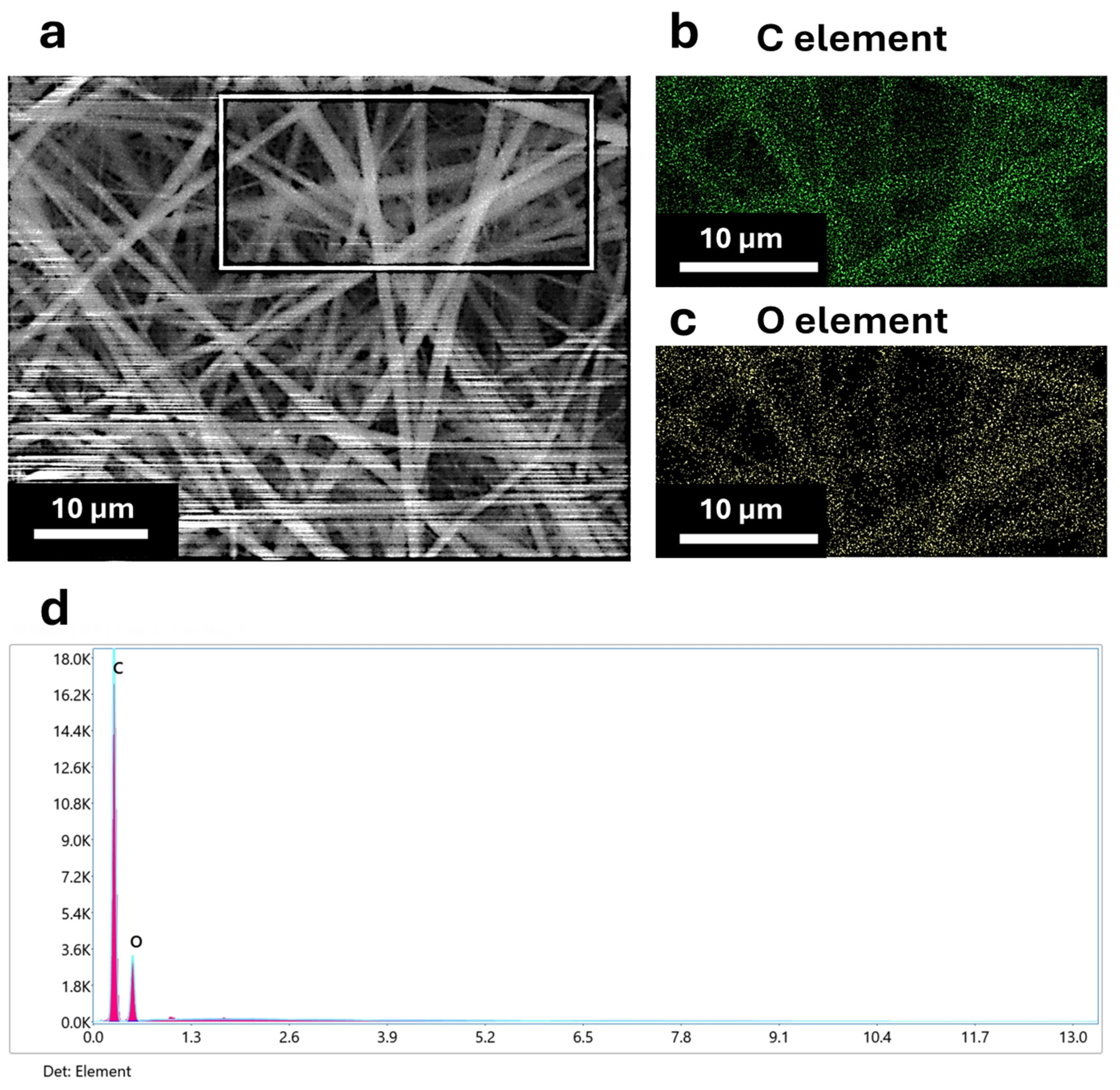
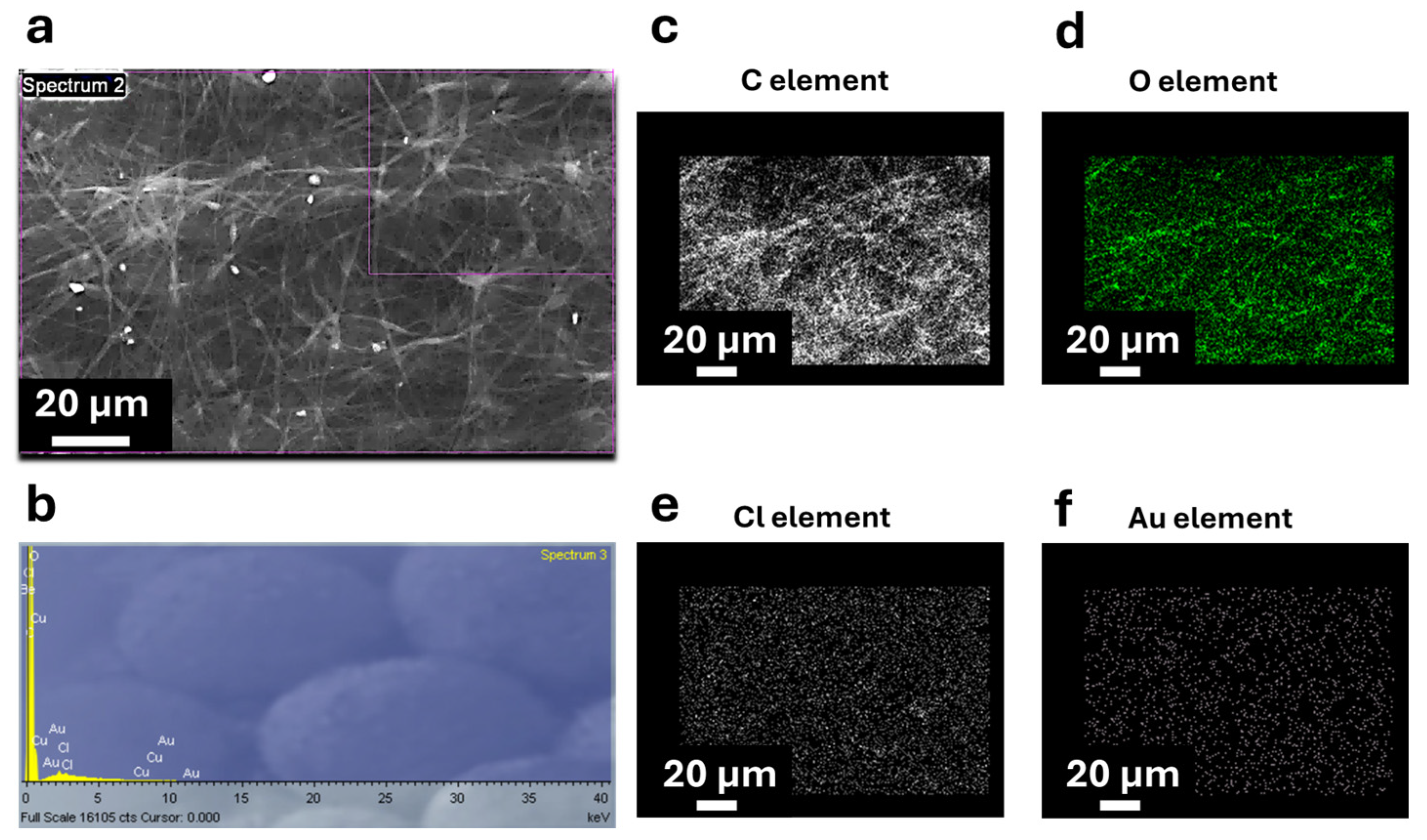
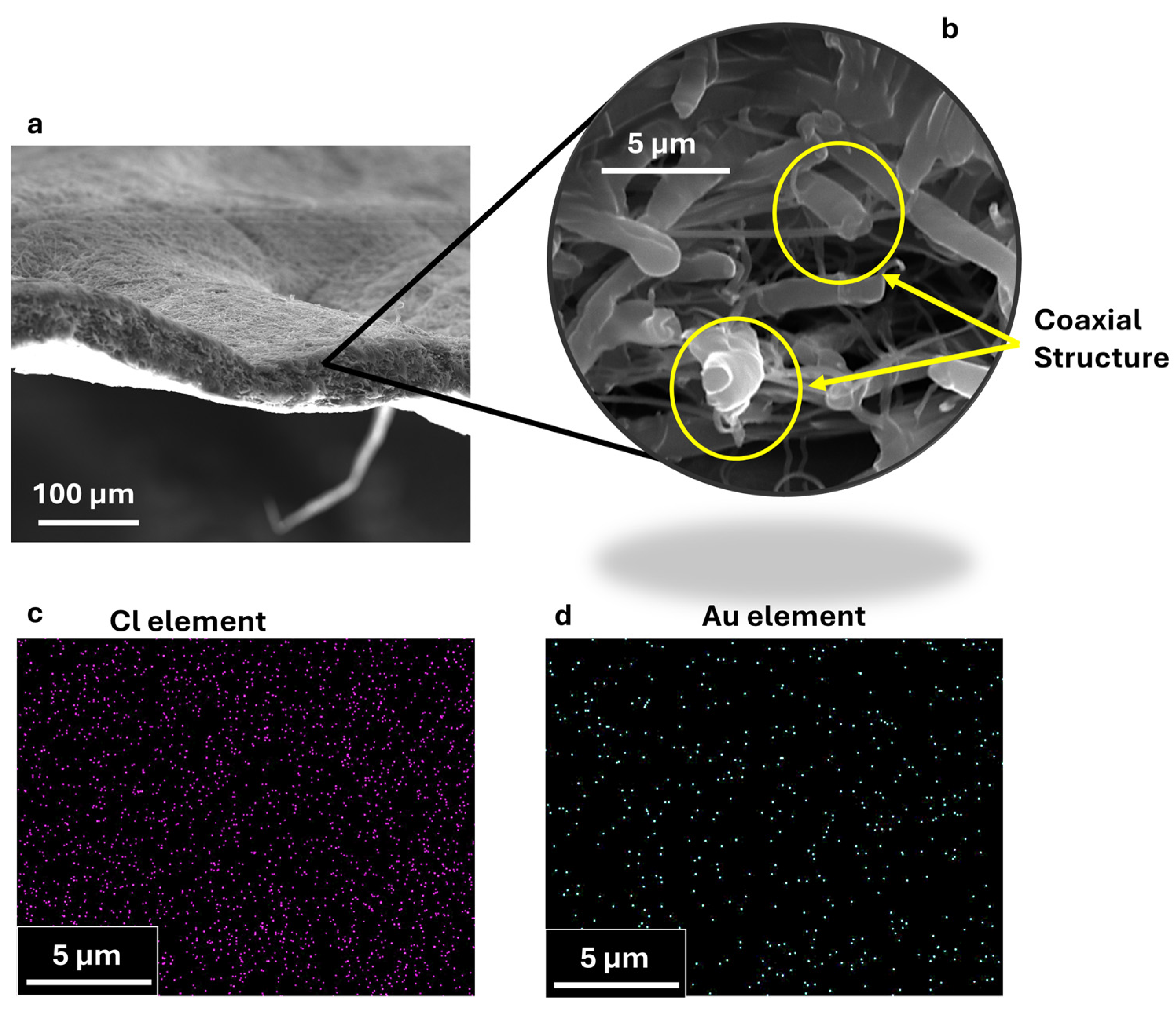
3.1. Morphological and Elemental Characterization of Coaxial Nanofibers

The coaxial electrospun membrane was characterized via SEM coupled with EDX to analyze the morphological and elemental composition. To ensure that the penetration factor of the X-ray could track the presence of AuM1 characteristic elements (Au and Cl) in EDX analysis, the nanofibers morphologies in top-view have been studied on non-metalized samples. In Figure 3, the top-view SEM-EDX of the 1%AuM1-Coax membrane is reported.
It is possible to notice that the only elements detected are carbon (C) and oxygen (O), which are characteristics of the PVA shell. If the coaxial structure had not been successfully produced, Au and Cl should also be present in the nanofibers (including the surface). The successful inclusion of AuM1 into the core of the coaxial membrane is confirmed by comparing the SEM-EDX results of 1%AuM1-Coax with the SEM-EDX analysis performed on uniaxial membranes of PCL loaded with 1%AuM1 (reported by the authors in a recent publication [7]). The results are reported in Figure 4.
In uniaxial electrospinning (no coaxial structure), Au and Cl peaks are detectable via EDX and are well distributed throughout the sample surface (the traces of Cu are probably due to the metallic collector used during the electrospinning). For this reason, comparing the top-views SEM-EDX of uniaxial and coaxial membranes loaded with AuM1 clearly shows that the gold complex must be in the nanofibers’ core.
Lastly, the cross-section SEM-EDX analysis was performed on 1%AuM1-Coax samples to analyze the section of the nanofibers. The SEM-EDX images are reported in Figure 5.
From the cross section (see Figure 5a,b), it is possible to recognize the nanofibers’ coaxial morphology, confirming their successful production during the coaxial electrospinning. Moreover, whereas in the top-view image of 1%AuM1-Coax (see Figure 3), the presence of Au and Cl are not detectable, in the cross-section images of Figure 5 (where the core of the nanofibers is exposed), it is possible to determine a uniform distribution of Cl and Au in the image, confirming that AuM1 was successfully included in the membrane and is in the core of the nanofibers.

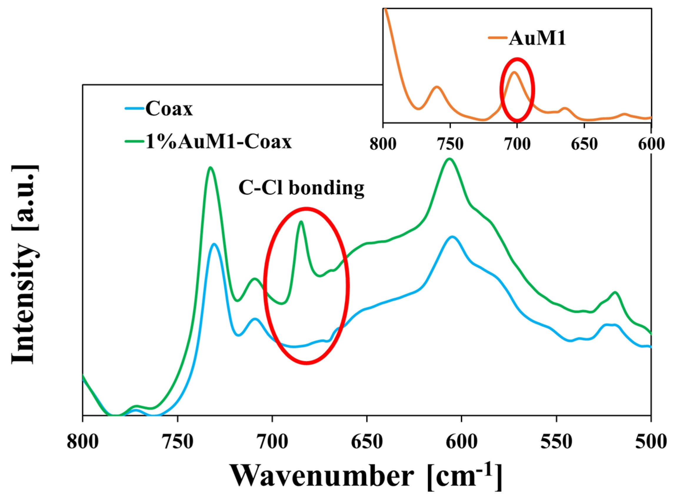
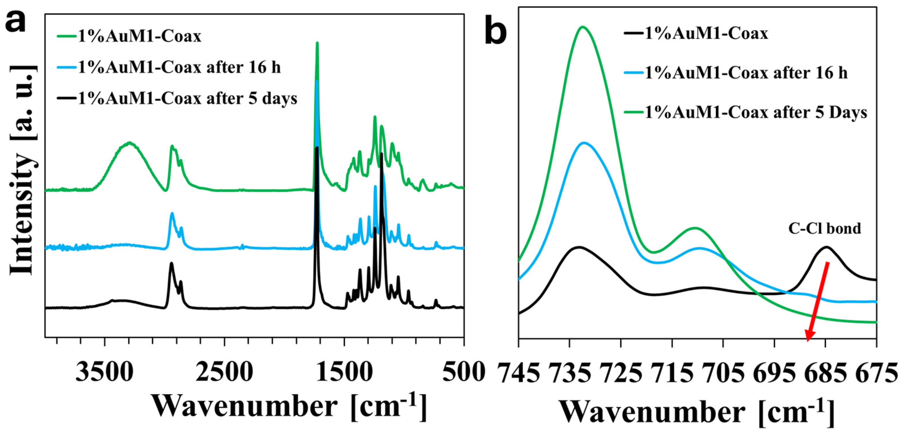
3.2. Fourier-Transform Infrared (FT-IR) Spectroscopy

FT-IR spectroscopy was performed on the various produced membranes to verify the presence of the typical groups of PCL and PVA in the 1%AuM1-Coax system, together with the FT-IR spectrum of AuM1. The obtained spectra are reported in Figure 6.
In Figure 6, it is possible to detect the typical peaks of the PCL (C-O-C stretching around 1200 cm−1, carbonyl group around 1735 cm−1 [38]) and of the PVA (-OH broad band around 3300 cm−1 [39], C-C at 839 cm−1 [40]). Both PCL and PVA signals are visible in the 1%AuM1-Coax spectrum. This confirms that the coaxial electrospinning of PCL-PVA membranes was successfully obtained. Regarding AuM1, the characteristic peaks of the phenyl group (1586 cm−1) [41] and the -OH broad band are observed [39]. Figure 7 shows the spectra of the unloaded coaxial membrane (Coax), the membrane loaded with the Au complex (1%AuM1-Coax), and the Au complex (AuM1, in the inset).
This signal at 685 cm−1 (slightly shifted with respect to the AuM1 complex) is due to the inclusion of AuM1 active substance in the PCL core. This is due to the two C-Cl bonds [42] (see Figure 1). The slight shift observed for this signal in the spectrum of the membrane is probably due to intermolecular interactions with polymeric matrices (PCL, PVA). This signal is absent from the FTIR spectrum of the unloaded coaxial membrane. This proves, together with other characterizations discussed below, the successful encapsulation of AuM1 in the coaxial membrane via FT-IR.

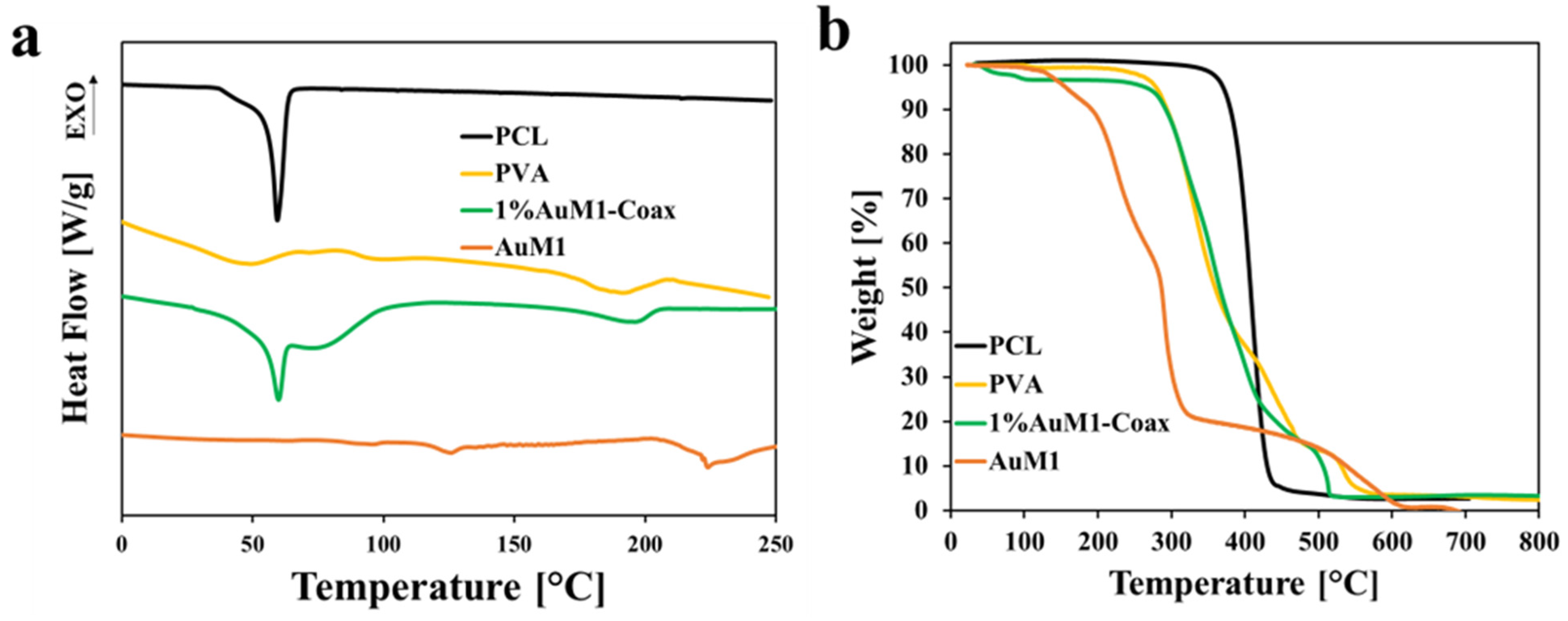
3.3. Thermal Characterization

Thermal characterizations of the membrane were performed to determine the thermal transitions and the crystallinity of the obtained membranes (see Figure 8).
The thermogravimetric analyses (see Figure 8b) show that the thermal degradation of the PVA and 1%AuM1-Coax start at similar temperatures [43]. In particular, Figure 8a compares the thermograms of PCL, PVA, 1%AuM1-Coax, and AuM1 samples. The comparison shows that the 1%AuM1-Coax sample manifests both the melting endotherms of PCL and PVA, confirming the presence of crystalline domains of both polymers in the nanofibers.
The 5% loss in weight (T5%WL) of 1%AuM1-Coax, defined as the temperature at which the weight decreases by 5% compared to the weight at room temperature, is around 270 °C. Moreover, no relevant thermal transitions or thermal degradations of AuM1 are determined up to around 150 °C, indicating that the complex is suitable for application in the biomedical field from a thermal point of view. This proves that these systems are thermally stable, considering the biomedical applications proposed in this research work.
In particular, Figure 8a compares the thermograms of PCL, PVA, 1%AuM1-Coax, and AuM1 samples. The comparison shows that 1%AuM1-Coax sample manifests both the melting endotherms of PCL and PVA, confirming the presence of crystalline domains of both polymers in the nanofibers.
Following previous research [44,45], coaxial electrospinning can affect the crystalline structure of the polymeric chains because of the two different polymeric solution flows and the changes in the evaporation conditions of the solvents with the environment (the core solvent evaporation being hindered by the presence of the shell). For this reason, the variations in crystallinity were determined by taking into account the mass fraction of each polymer. The equations used for the evaluation of the crystallinity are reported in Equations (1) and (2), where X P C L is the crystallinity of PCL, Δ H m P C L is the melting enthalpy of the PCL (evaluated by taking in consideration endothermic event between 20 °C and 80 °C), α P C L is the fraction of PCL, and Δ H 100 % m P C L is the melting enthalpy of 100% crystalline PCL (136.1 J/g) [46]. Similarly, X P V A is the crystallinity of PVA, Δ H m P V A is the melting enthalpy of the PVA (evaluated by taking in consideration the endothermic event between 150 °C and 230 °C), αPVA is the fraction of PVA, and Δ H 100 % m P V A is the melting enthalpy of 100% crystalline PVA (138.0 J/g) [47].
X P C L = Δ H m P C L α P C L Δ H 100 % m P C L 100
X P V A = Δ H m P V A α P V A Δ H 100 % m P V A 100
In this case, α P V A and α P C L were evaluated by dissolving the coaxial system in water for 24 h (ensuring the complete dissolution of PVA). By the gravimetric difference before and after the dissolution of PVA, it was found that the PCL fraction was 0.438 in wt., whereas the PVA fraction was 0.562 in wt.
In this way, the crystallinity of PCL and PVA was evaluated by the DSC analysis according to Enayati et al. [48] (see Table 4).
In agreement with previous results [49], the crystallinity of PVA and PCL slightly increases in coaxial electrospinning. This is probably due to the changes in the evaporation rate during the process. However, the melting temperatures of the polymers (60 °C and 197 °C for PCL and PVA, respectively) are substantially unchanged.

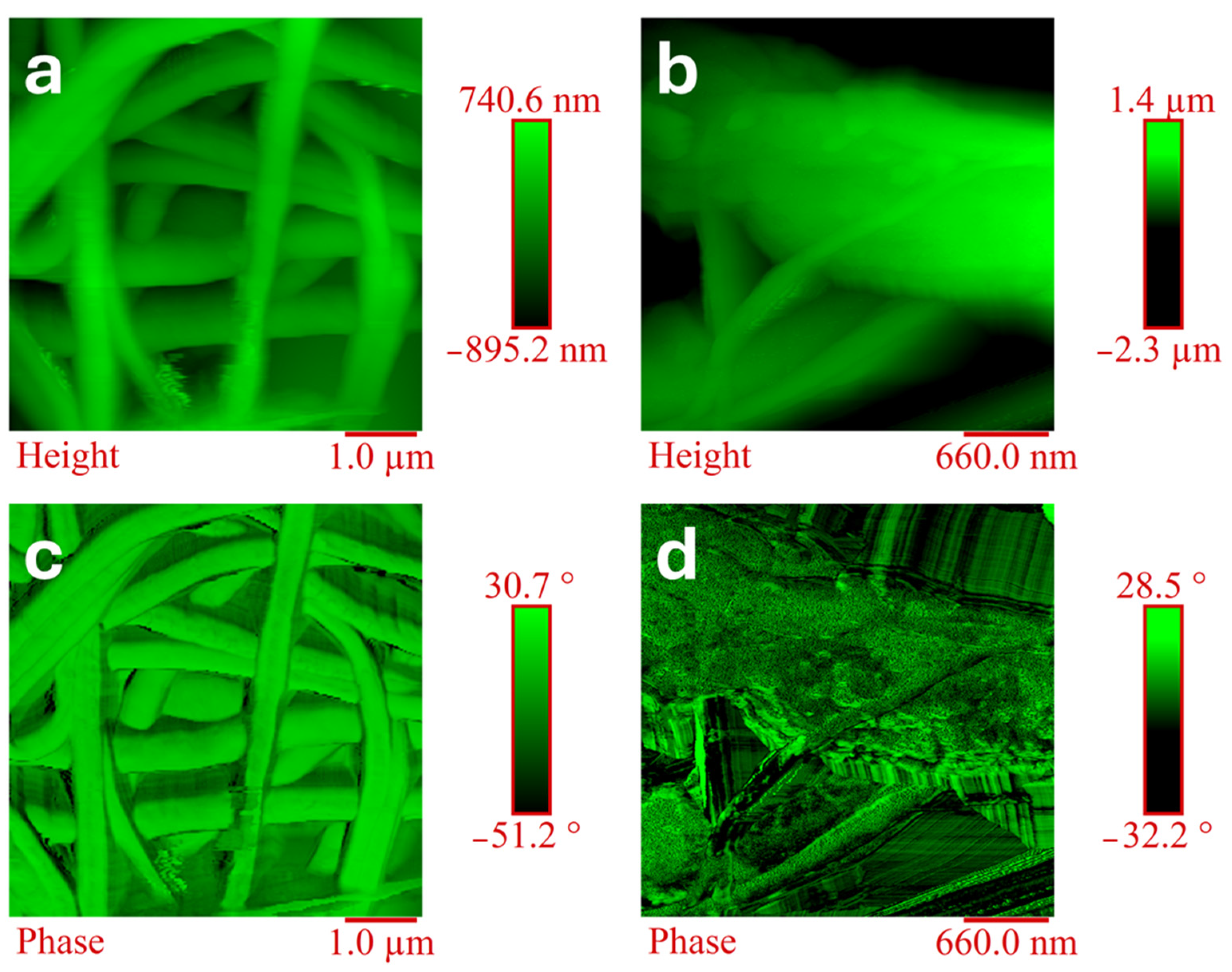
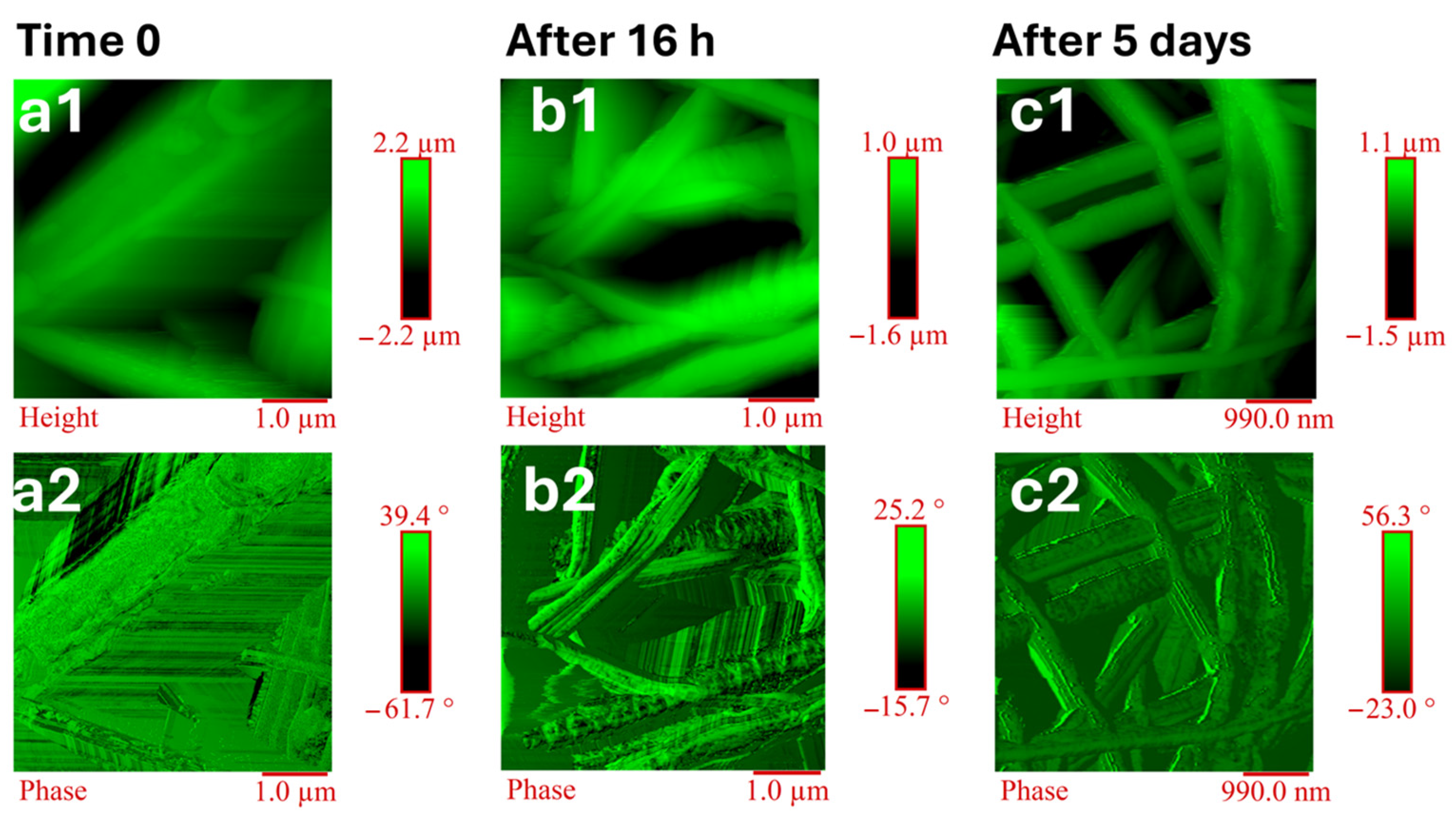
3.4. Morphological Analysis: Atomic Force Microscopy (AFM)

The superficial morphology of the coaxial nanofibers was accurately characterized via AFM investigation. The morphology of the 1%AuM1-Coax is sensitively different from the PCL uniaxial membrane (see Figure 9).
The surface of 1%AuM1-Coax shows the presence of polymeric bulges, and the fibers are generally thicker than the PCL uniaxial system. This is probably because the PVA shell covers the PCL core. In fact, as is evident in Figure 9c,d, the phase AFM image of the fiber surface is highly smooth in the case of PCL, contrary to the coaxial system. Moreover, 1%AuM1-Coax also shows lamellar structures, which are probably characteristics of the PVA crystalline structure.

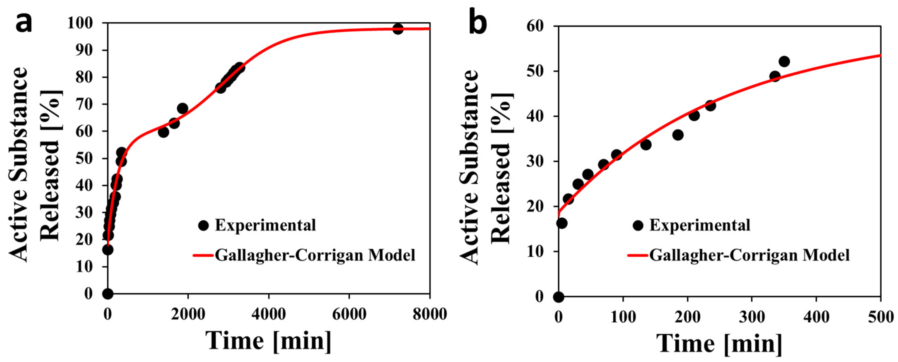
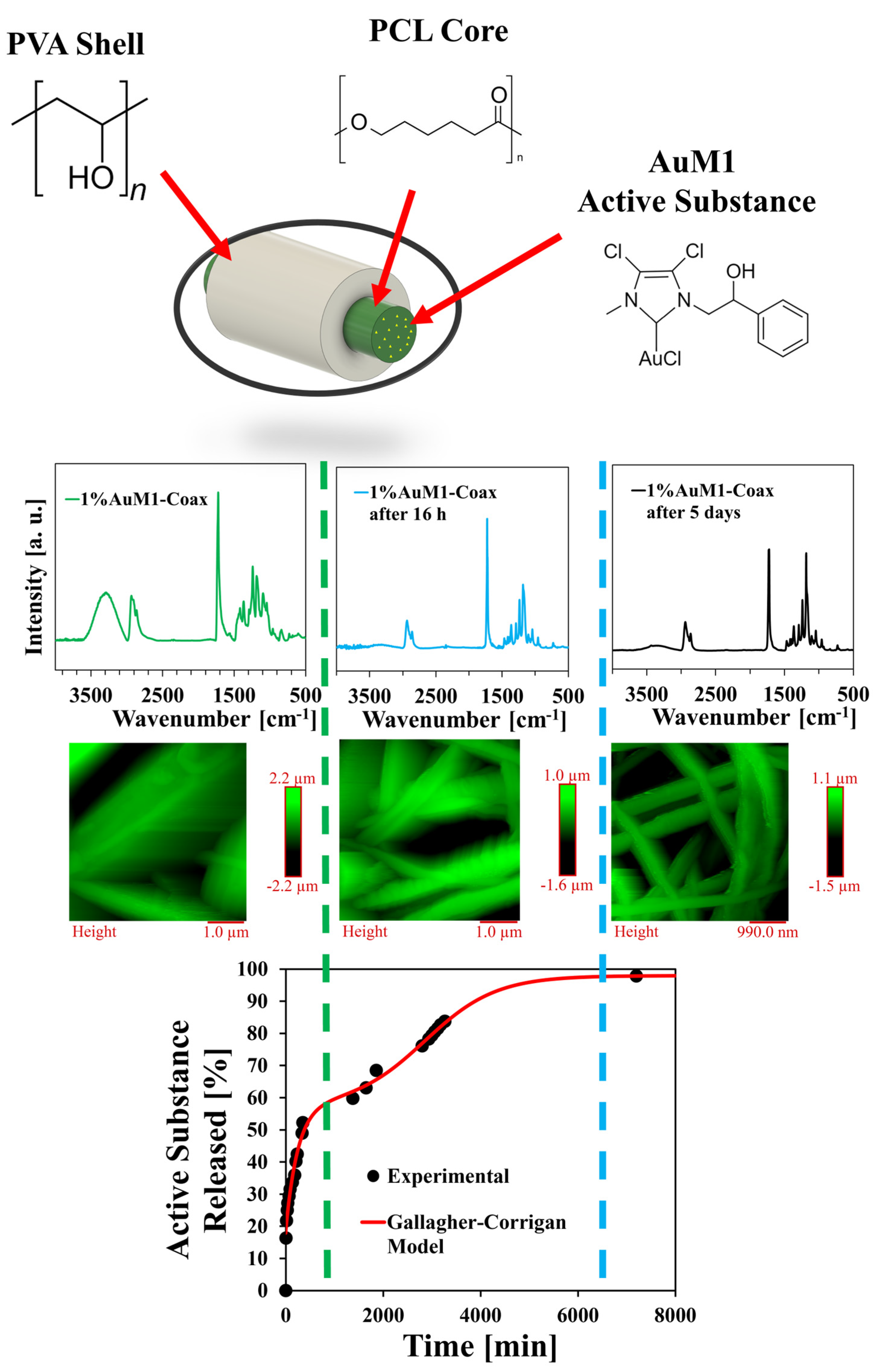
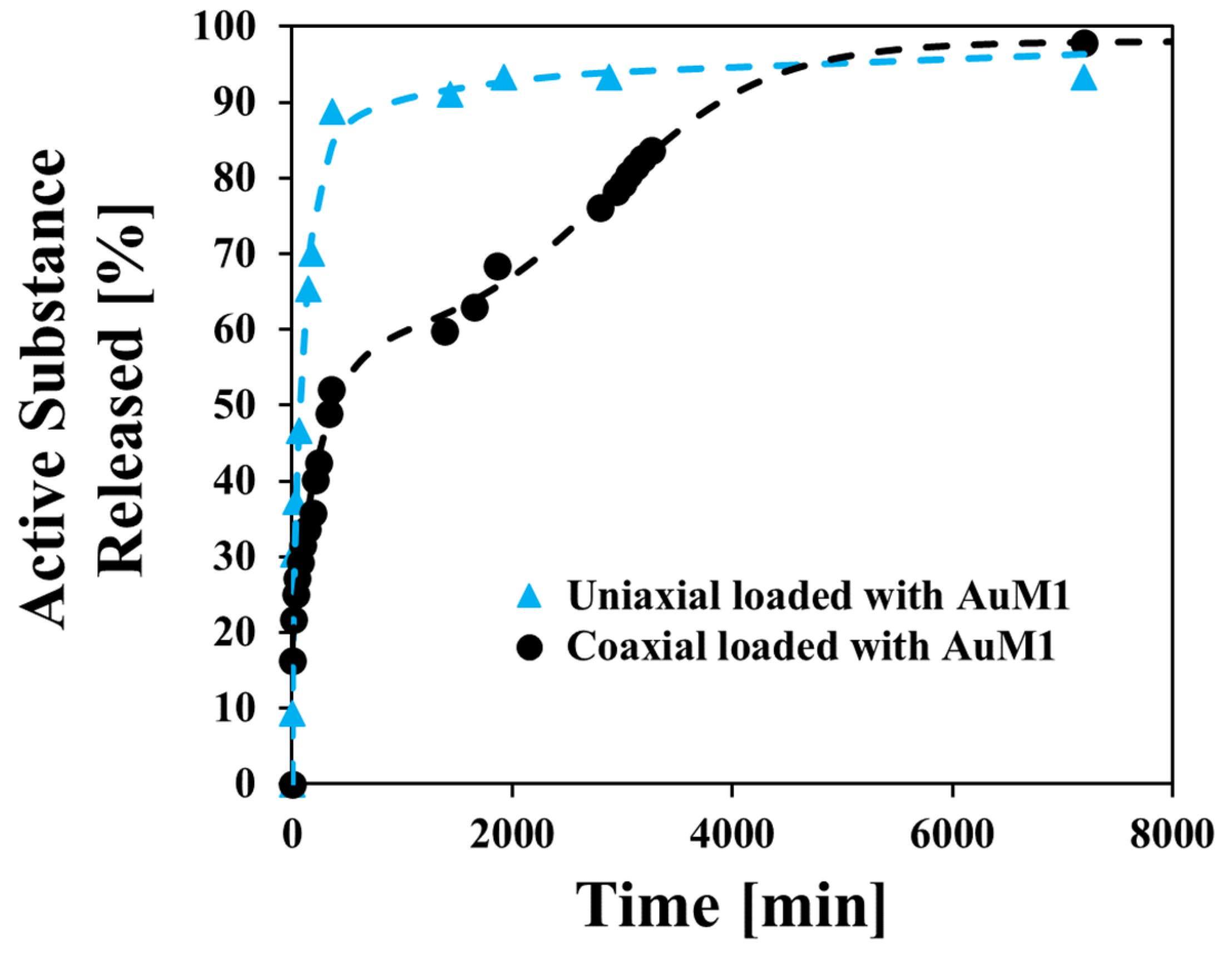
3.5. Release Kinetics

The presence of a PVA shell (soluble in water) in 1%AuM1-Coax sensitively affects the release kinetics in physiological solutions because its erosion occurs during the hours of release and slows the release of the active substance. However, it is reasonable that during the first hours, when the erosion occurs, there is a simultaneous swelling of the hydrophilic PVA [50], with the consequent absorption of PBS from the membrane, which causes an initial release of the active substance into the core. Then, when the PVA is dissolved, the AuM1 diffusion phenomenon from the PCL to the surrounding environment becomes predominant. For this reason, the release kinetics of 1%AuM1-Coax in physiological conditions are multi-step, as observed in Figure 10a.
Different mathematical models have been proposed in the literature for fitting multi-step curves. The Gallagher–Corrigan model is very efficient in describing release kinetics, including the erosion and simultaneous diffusion of the active substance [51,52]. Furthermore, recent research papers have proposed this model for electrospun membranes [53] made of hydrophobic/hydrophilic polymers [54]. The model is reported in Equation (3).
X t = A + X 1 1 e C 1 t   + X 2 e C 2 t m a x t 1 + e C 2 t m a x t
In this case, X(t) is the fraction of active substance that was released over time, A is the burst, X1 and X2 are the fraction step contribution, C1 and C2 are the first order kinetic factors, and tmax is the time at which the maximum drug release rate is observed (referred to the second step) [55].
Table 5 reports the fitting parameters of the Gallagher–Corrigan Model. Following the literature, the model reports that the erodible shell’s presence sensitively limits the burst. Moreover, the maximum drug release rate of the second step is around 48 h (2880 min), indicating that this nanofiber design guarantees control of the release kinetics for a more extended period.
The PVA shell erosion occurs during the release tests in the PBS solution. This phenomenon was confirmed morphologically (see Figure 11) and spectroscopically (see Figure 12) over time. As reported in Figure 11, several morphological differences exist between the membrane at time 0 and after 16 h of release. It is possible to notice that the membranes, after 16 h of release, have smoother fibers and the bulges disappear on their surface. This suggests that the PVA shell was eroded; after 16 h, the fiber morphology is highly similar to the one reported in Figure 9a–c (PCL uniaxial system). Moreover, the lamellar structure (probably characteristic of the PVA shell) was replaced by the smooth structure of PCL. The erosion of the PVA after 16 h is confirmed by FTIR spectra, observing a strong reduction in the peculiar peaks of PVA (e.g., -OH band around 3300–3400 cm−1). At the same time, the C-Cl peak due to the presence of AuM1 (see Figure 12b) starts to decrease since its release in the PBS. In fact, after 16 h, it is possible to observe a shoulder around 685 cm−1, which disappears after 5 days of release, indicating its full release in the physiological environment.
The images reported in Figure 11 clearly show that the fibers’ diameters are reduced after the drug release test, as evident by comparing the images at time 0 (shell-core structure) and the images acquired after 5 days of the test (shell-eroded structure), indicating that shell erosion leaves an integer insoluble core. AFM and FTIR analyses prove that the release kinetic profile is a consequence of the coaxial nanofiber membranes’ morphology and chemical nature. Figure 13 proposes a scheme for interpreting the correlation among morphology, spectroscopy, and release kinetic data.
Figure 13 summarizes the innovative approach of monitoring the steps detectable in the drug release curves by tracking the evolution of morphology. The evolution of the morphology is strictly linked to the evolution of the chemical structure of the nanofibers due to the PVA dissolution in water. In this way, a comprehensive study of the mechanisms that rule the drug release can be performed.
In a previous study [7], the research group obtained membranes of PCL filled with 1%AuM1 (analogous to the “core” of 1%AuM1-Coax membrane). The results obtained for the coaxial system with the results obtained in the uniaxial configuration were compared (where AuM1 tended to be released in a few hours because of its aggregation on the nanofiber surface, causing the relevant burst effect [7]). The different behavior between the uniaxial and coaxial loaded samples is visible in Figure 14.
The coaxial electrospinning process, with the proper design of the nanofiber architecture (biodegradable shell and hydrophobic core filled with the active substance), is an effective strategy for greatly tuning the release kinetic of chemotherapy agents from electrospun membranes.

4. Conclusions

In the current research paper, coaxial electrospun membranes containing the antitumoral active agent (AuM1) were developed. The synthetic antitumoral agent was chosen for its activity against melanoma. During electrospinning, membranes made of coaxial nanofibers with a PVA (water soluble) shell and a PCL (hydrophobic) core were produced. The active agent was loaded inside the core section, and its drug release was monitored in a physiological environment. Interestingly, the design of coaxial nanofibers allows for sustained release for about 3 days. By comparison, similar PCL membranes loaded with AuM1 and obtained via uniaxial electrospinning manifest a burst release of 90% of AuM1 in about 1 h. The nanofibrous membrane’s morphology and chemical structure were monitored over the release time via AFM and FTIR, respectively, revealing the various steps in which the drug release occurs. This study highlights efficient ways of producing polymeric devices for sustained release to apply for the better control of antitumoral treatments.

Supplementary Materials

The following supporting information can be downloaded at: https://www.mdpi.com/article/10.3390/fib12120101/s1.

Author Contributions

Conceptualization, R.L. and L.G.; methodology, L.V., F.A., A.M. and M.R.; software, L.V., F.A., A.M. and M.R.; validation, R.L., F.A., M.R., P.L. and L.G.; formal analysis, R.L., L.V., F.A. and A.M.; investigation, R.L., M.R. and A.M.; resources, P.L. and L.G.; data curation, R.L., L.V., F.A., A.M., M.R. and L.G.; writing—original draft preparation, R.L. and L.G.; writing—review and editing, R.L. and L.G.; visualization, R.L., L.V., P.L. and L.G.; supervision, P.L. and L.G.; project administration, P.L. and L.G.; funding acquisition, P.L. and L.G. All authors have read and agreed to the published version of the manuscript.

Funding

This research received no external funding.

Data Availability Statement

Data are contained within the article and Supplementary Materials.

Acknowledgments

The authors kindly thank Maria Sarno, Claudia Cirillo, and Mariagrazia Iuliano for their support in performing SEM-EDX analysis on the coaxial membranes.

Conflicts of Interest

The authors declare no conflicts of interest.

References

  1. Rahim, M.A.; Jan, N.; Khan, S.; Shah, H.; Madni, A.; Khan, A.; Jabar, A.; Khan, S.; Elhissi, A.; Hussain, Z.; et al. Recent Advancements in Stimuli Responsive Drug Delivery Platforms for Active and Passive Cancer Targeting. Cancers 2021, 13, 670. [Google Scholar] [CrossRef] [PubMed]
  2. Ziegler, R.; Ilyas, S.; Mathur, S.; Goya, G.F.; Fuentes-García, J.A. Remote-Controlled Activation of the Release through Drug-Loaded Magnetic Electrospun Fibers. Fibers 2024, 12, 48. [Google Scholar] [CrossRef]
  3. Catauro, M.; D’Angelo, A.; Fiorentino, M.; Pacifico, S.; Latini, A.; Brutti, S.; Vecchio Ciprioti, S. Thermal, Spectroscopic Characterization and Evaluation of Antibacterial and Cytotoxicity Properties of Quercetin-PEG-Silica Hybrid Materials. Ceram. Int. 2023, 49, 14855–14863. [Google Scholar] [CrossRef]
  4. Catauro, M.; D’errico, Y.; D’angelo, A.; Clarke, R.J.; Blanco, I. Antibacterial Activity and Iron Release of Organic-inorganic Hybrid Biomaterials Synthesized via the Sol-gel Route. Appl. Sci. 2021, 11, 9311. [Google Scholar] [CrossRef]
  5. Balasubramaniam, B.; Prateek; Ranjan, S.; Saraf, M.; Kar, P.; Singh, S.P.; Thakur, V.K.; Singh, A.; Gupta, R.K. Antibacterial and Antiviral Functional Materials: Chemistry and Biological Activity toward Tackling COVID-19-like Pandemics. ACS Pharmacol. Transl. Sci. 2021, 4, 8–54. [Google Scholar] [CrossRef]
  6. Longo, R.; Raimondo, M.; Vertuccio, L.; Ciardulli, M.C.; Sirignano, M.; Mariconda, A.; Della Porta, G.; Guadagno, L. Bottom-Up Strategy to Forecast the Drug Location and Release Kinetics in Antitumoral Electrospun Drug Delivery Systems. Int. J. Mol. Sci. 2023, 24, 1507. [Google Scholar] [CrossRef]
  7. Guadagno, L.; Raimondo, M.; Vertuccio, L.; Lamparelli, E.P.; Ciardulli, M.C.; Longo, P.; Mariconda, A.; Della Porta, G.; Longo, R. Electrospun Membranes Designed for Burst Release of New Gold-Complexes Inducing Apoptosis of Melanoma Cells. Int. J. Mol. Sci. 2022, 23, 7147. [Google Scholar] [CrossRef]
  8. Longo, R.; Guadagno, L.; Lamberti, P. Electromagnetic Characterization of Polycaprolactone Electrospun Nanofibers Filled with Fe3O4 Nanoparticles. In Proceedings of the 2020 4th International Symposium on Multidisciplinary Studies and Innovative Technologies (ISMSIT), Istanbul, Turkey, 22 October 2020; pp. 1–5. [Google Scholar]
  9. Wang, Z.; Zhao, Y.; Shen, M.; Tomás, H.; Zhou, B.; Shi, X. Antitumor Efficacy of Doxorubicin-Loaded Electrospun Attapulgite–Poly(Lactic-co-glycolic Acid) Composite Nanofibers. J. Funct. Biomater. 2022, 13, 55. [Google Scholar] [CrossRef]
  10. Leppert, W.; Malec-Milewska, M.; Zajaczkowska, R.; Wordliczek, J. Transdermal and Topical Drug Administration in the Treatment of Pain. Molecules 2018, 23, 681. [Google Scholar] [CrossRef]
  11. Affaitati, G.; Costantini, R.; Tana, C.; Lapenna, D.; Schiavone, C.; Cipollone, F.; Adele Giamberardino, M. Effects of Topical vs Injection Treatment of Cervical Myofascial Trigger Points on Headache Symptoms in Migraine Patients: A Retrospective Analysis. J. Headache Pain 2018, 19, 104. [Google Scholar] [CrossRef]
  12. Li, D.; Xu, K.; Niu, Z.; Zhang, C. Annealing and Plasma Effects on the Structural and Photocatalytic Properties of TiO2 Fibers Produced by Electrospinning. Catalysts 2022, 12, 1441. [Google Scholar] [CrossRef]
  13. Luraghi, A.; Peri, F.; Moroni, L. Electrospinning for Drug Delivery Applications: A Review. J. Control. Release 2021, 334, 463–484. [Google Scholar] [CrossRef] [PubMed]
  14. Wu, J.; Zhang, Z.; Gu, J.; Zhou, W.; Liang, X.; Zhou, G.; Han, C.C.; Xu, S.; Liu, Y. Mechanism of a Long-Term Controlled Drug Release System Based on Simple Blended Electrospun Fibers. J. Control. Release 2020, 320, 337–346. [Google Scholar] [CrossRef] [PubMed]
  15. Chen, K.; Li, Y.; Li, Y.; Tan, Y.; Liu, Y.; Pan, W.; Tan, G. Stimuli-Responsive Electrospun Nanofibers for Drug Delivery, Cancer Therapy, Wound Dressing, and Tissue Engineering. J. Nanobiotechnol. 2023, 21, 237. [Google Scholar] [CrossRef]
  16. Han, D.; Steckl, A.J. Coaxial Electrospinning Formation of Complex Polymer Fibers and Their Applications. Chempluschem 2019, 84, 1453–1497. [Google Scholar] [CrossRef]
  17. Coimbra, P.; Santos, P.; Alves, P.; Miguel, S.P.; Carvalho, M.P.; de Sá, K.D.; Correia, I.J.; Ferreira, P. Coaxial Electrospun PCL/Gelatin-MA Fibers as Scaffolds for Vascular Tissue Engineering. Colloids Surf. B Biointerfaces 2017, 159, 7–15. [Google Scholar] [CrossRef]
  18. Lan, X.; Liu, Y.; Wang, Y.; Tian, F.; Miao, X.; Wang, H.; Tang, Y. Coaxial Electrospun PVA/PCL Nanofibers with Dual Release of Tea Polyphenols and ε-Poly (L-Lysine) as Antioxidant and Antibacterial Wound Dressing Materials. Int. J. Pharm. 2021, 601, 120525. [Google Scholar] [CrossRef]
  19. Lu, Y.; Huang, J.; Yu, G.; Cardenas, R.; Wei, S.; Wujcik, E.K.; Guo, Z. Coaxial Electrospun Fibers: Applications in Drug Delivery and Tissue Engineering. WIREs Nanomed. Nanobiotechnol. 2016, 8, 654–677. [Google Scholar] [CrossRef]
  20. Duan, G.; Jin, M.; Wang, F.; Greiner, A.; Agarwal, S.; Jiang, S. Core Effect on Mechanical Properties of One Dimensional Electrospun Core-Sheath Composite Fibers. Compos. Commun. 2021, 25, 100773. [Google Scholar] [CrossRef]
  21. Schulte, V.A.; Díez, M.; Möller, M.; Lensen, M.C. Surface Topography Induces Fibroblast Adhesion on Intrinsically Nonadhesive Poly(Ethylene Glycol) Substrates. Biomacromolecules 2009, 10, 2795–2801. [Google Scholar] [CrossRef]
  22. Schmidt, B.V.K.J. Hydrophilic Polymers. Polymers 2019, 11, 693. [Google Scholar] [CrossRef] [PubMed]
  23. Wen, J.; Wang, S.; Guo, R.; Liu, D. CSF1R Inhibitors Are Emerging Immunotherapeutic Drugs for Cancer Treatment. Eur. J. Med. Chem. 2023, 245, 114884. [Google Scholar] [CrossRef] [PubMed]
  24. Fan, K.; Xi, J.; Fan, L.; Wang, P.; Zhu, C.; Tang, Y.; Xu, X.; Liang, M.; Jiang, B.; Yan, X.; et al. In Vivo Guiding Nitrogen-Doped Carbon Nanozyme for Tumor Catalytic Therapy. Nat. Commun. 2018, 9, 1440. [Google Scholar] [CrossRef] [PubMed]
  25. Zhang, J.; Wang, X.; Liu, T.; Liu, S.; Jing, X. Antitumor Activity of Electrospun Polylactide Nanofibers Loaded with 5-Fluorouracil and Oxaliplatin against Colorectal Cancer. Drug Deliv. 2016, 23, 794–800. [Google Scholar] [CrossRef]
  26. Mcdonald, M.; Oktaria, S.; Konstantinov, K. Coaxially Electrospun 5-Fluorouracil-Loaded PLGA/PVP Fibrous Membrane for Skin Tumor Treatment. Biomed. Mater. 2021, 16, 065014. [Google Scholar] [CrossRef]
  27. Ignatova, M.; Yossifova, L.; Gardeva, E.; Manolova, N.; Toshkova, R.; Rashkov, I.; Alexandrov, M. Bioactive and Comaptible Polymers Antiproliferative Activity of Nanofibers Containing Quaternized Chitosan and/or Doxorubicin against MCF-7 Human Breast Carcinoma Cell Line by Apoptosis. J. Bioact. Compat. Polym. 2011, 26, 539–551. [Google Scholar] [CrossRef]
  28. Iacopetta, D.; Rosano, C.; Sirignano, M.; Mariconda, A.; Ceramella, J.; Ponassi, M.; Saturnino, C.; Sinicropi, M.S.; Longo, P. Is the Way to Fight Cancer Paved with Gold? Metal-Based Carbene Complexes with Multiple and Fascinating Biological Features. Pharmaceuticals 2020, 13, 91. [Google Scholar] [CrossRef]
  29. Ghosh, S. Cisplatin: The First Metal Based Anticancer Drug. Bioorg. Chem. 2019, 88, 102925. [Google Scholar] [CrossRef]
  30. Mariconda, A.; Sirignano, M.; Costabile, C.; Longo, P. New NHC-Silver and Gold Complexes Active in A3-Coupling (Aldehyde-Alkyne-Amine) Reaction. Mol. Catal. 2020, 480, 110570. [Google Scholar] [CrossRef]
  31. Haider, A.; Haider, S.; Kang, I.K. A Comprehensive Review Summarizing the Effect of Electrospinning Parameters and Potential Applications of Nanofibers in Biomedical and Biotechnology. Arab. J. Chem. 2018, 11, 1165–1188. [Google Scholar] [CrossRef]
  32. Zhou, H.; Shi, Z.; Wan, X.; Fang, H.; Yu, D.G.; Chen, X.; Liu, P. The Relationships between Process Parameters and Polymeric Nanofibers Fabricated Using a Modified Coaxial Electrospinning. Nanomaterials 2019, 9, 843. [Google Scholar] [CrossRef] [PubMed]
  33. Abdulhussain, R.; Adebisi, A.; Conway, B.R.; Asare-Addo, K. Electrospun Nanofibers: Exploring Process Parameters, Polymer Selection, and Recent Applications in Pharmaceuticals and Drug Delivery. J. Drug Deliv. Sci. Technol. 2023, 90, 105156. [Google Scholar] [CrossRef]
  34. Zargham, S.; Bazgir, S.; Tavakoli, A.; Rashidi, A.S.; Damerchely, R. The Effect of Flow Rate on Morphology and Deposition Area of Electrospun Nylon 6 Nanofiber. J. Eng. Fiber Fabr. 2012, 7, 42–49. [Google Scholar] [CrossRef]
  35. Keirouz, A.; Wang, Z.; Reddy, V.S.; Nagy, Z.K.; Vass, P.; Buzgo, M.; Ramakrishna, S.; Radacsi, N. The History of Electrospinning: Past, Present, and Future Developments. Adv. Mater. Technol. 2023, 8, 2201723. [Google Scholar] [CrossRef]
  36. Guadagno, L.; Sorrentino, A.; Longo, R.; Raimondo, M. Multifunctional Properties of Polyhedral Oligomeric Silsesquioxanes (POSS)-Based Epoxy Nanocomposites. Polymers 2023, 15, 2297. [Google Scholar] [CrossRef]
  37. Hopkins, E.; Sanvictores, T.; Sharma, S. Physiology, Acid Base Balance. Urolithiasis 2022, 19–22. [Google Scholar] [CrossRef]
  38. Phillipson, K.; Hay, J.N.; Jenkins, M.J. Thermal Analysis FTIR Spectroscopy of Poly(ε-Caprolactone). Thermochim. Acta 2014, 595, 74–82. [Google Scholar] [CrossRef]
  39. Mansur, H.S.; Sadahira, C.M.; Souza, A.N.; Mansur, A.A.P. FTIR Spectroscopy Characterization of Poly (Vinyl Alcohol) Hydrogel with Different Hydrolysis Degree and Chemically Crosslinked with Glutaraldehyde. Mater. Sci. Eng. C 2008, 28, 539–548. [Google Scholar] [CrossRef]
  40. Kharazmi, A.; Faraji, N.; Hussin, R.M.; Saion, E.; Yunus, W.M.M.; Behzad, K. Structural, Optical, Opto-Thermal and Thermal Properties of ZnS-PVA Nanofluids Synthesized through a Radiolytic Approach. Beilstein J. Nanotechnol. 2015, 6, 529–536. [Google Scholar] [CrossRef]
  41. Şen, P.; Hirel, C.; Andraud, C.; Aronica, C.; Bretonnière, Y.; Mohammed, A.; Ågren, H.; Minaev, B.; Minaeva, V.; Baryshnikov, G.; et al. Fluorescence and FTIR Spectra Analysis of Trans-A2B2-Substituted Di- and Tetra-Phenyl Porphyrins. Materials 2010, 3, 4446–4475. [Google Scholar] [CrossRef]
  42. De Lorenzi, A.; Giorgianni, S.; Bini, R. High-Resolution FTIR Spectroscopy of the C—Cl Stretching Mode of Vinyl Chloride. Mol. Phys. 1999, 96, 101–108. [Google Scholar] [CrossRef]
  43. Peng, Z.; Kong, L.X. A Thermal Degradation Mechanism of Polyvinyl Alcohol/Silica Nanocomposites. Polym. Degrad. Stab. 2007, 92, 1061–1071. [Google Scholar] [CrossRef]
  44. Luo, H.; Huang, Y.; Wang, D.; Shi, J. Coaxial-Electrospinning as a New Method to Study Confined Crystallization of Polymer. J. Polym. Sci. B Polym. Phys. 2013, 51, 376–383. [Google Scholar] [CrossRef]
  45. Ero-Phillips, O.; Jenkins, M.; Stamboulis, A. Tailoring Crystallinity of Electrospun Plla Fibres by Control of Electrospinning Parameters. Polymers 2012, 4, 1331–1348. [Google Scholar] [CrossRef]
  46. Longo, R.; Vertuccio, L.; Speranza, V.; Pantani, R.; Raimondo, M.; Calabrese, E.; Guadagno, L. Nanometric Mechanical Behavior of Electrospun Membranes Loaded with Magnetic Nanoparticles. Nanomaterials 2023, 13, 1252. [Google Scholar] [CrossRef]
  47. Reguieg, F.; Ricci, L.; Bouyacoub, N.; Belbachir, M.; Bertoldo, M. Thermal Characterization by DSC and TGA Analyses of PVA Hydrogels with Organic and Sodium MMT. Polym. Bull. 2020, 77, 929–948. [Google Scholar] [CrossRef]
  48. Enayati, M.S.; Behzad, T.; Sajkiewicz, P.; Bagheri, R.; Ghasemi-Mobarakeh, L.; Łojkowski, W.; Pahlevanneshan, Z.; Ahmadi, M. Crystallinity Study of Electrospun Poly (Vinyl Alcohol) Nanofibers: Effect of Electrospinning, Filler Incorporation, and Heat Treatment. Iran. Polym. J. 2016, 25, 647–659. [Google Scholar] [CrossRef]
  49. Longo, R.; Catauro, M.; Sorrentino, A.; Guadagno, L. Thermal and Mechanical Characterization of Complex Electrospun Systems Based on Polycaprolactone and Gelatin. J. Therm. Anal. Calorim. 2022, 147, 5391–5399. [Google Scholar] [CrossRef]
  50. Pant, B.; Park, M.; Park, S.J. Drug Delivery Applications of Core-Sheath Nanofibers Prepared by Coaxial Electrospinning: A Review. Pharmaceutics 2019, 11, 305. [Google Scholar] [CrossRef]
  51. Gallagher, K.M.; Corrigan, O.I. Mechanistic Aspects of the Release of Levamisole Hydrochloride from Biodegradable Polymers. J. Control. Release 2000, 69, 261–272. [Google Scholar] [CrossRef]
  52. Potseleev, V.; Uspenskii, S.; Trofimchuk, E.; Bolshakova, A.; Kasatova, A.; Kasatov, D.; Taskaev, S. Nanocomposite Materials Based on Polylactide and Gold Complex Compounds for Absorbed Dose Diagnostics in BNCT. Int. J. Mol. Sci. 2023, 24, 16492. [Google Scholar] [CrossRef] [PubMed]
  53. Lamarra, J.; Calienni, M.N.; Rivero, S.; Pinotti, A. Electrospun Nanofibers of Poly(Vinyl Alcohol) and Chitosan-Based Emulsions Functionalized with Cabreuva Essential Oil. Int. J. Biol. Macromol. 2020, 160, 307–318. [Google Scholar] [CrossRef] [PubMed]
  54. Soleimani, F.; Pellerin, C.; Omidfar, K.; Bagheri, R. Engineered Robust Hydrophobic/Hydrophilic Nanofibrous Scaffolds with Drug-Eluting, Antioxidant, and Antimicrobial Capacity. ACS Appl. Bio Mater. 2024, 7, 3687–3700. [Google Scholar] [CrossRef] [PubMed]
  55. Balcerzak, J.; Mucha, M. Analysis of model drug release kinetics from complex matrices of polylactide-chitosan. Prog. Chem. Appl. Chitin Deriv. 2010, 15, 117–126. [Google Scholar]
Figure 1. Schematization of AuM1 synthesis steps.
Fibers 12 00101 g001
Figure 2. Coaxial electrospinning scheme.
Fibers 12 00101 g002
Figure 3. (a) SEM-EDX of 1%AuM1-Coax in top-view (the box indicates the area in which the elemental analysis is performed); (b) elemental mapping of carbon; (c) elemental mapping of oxygen; (d) EDX spectrum of the analyzed region.
Fibers 12 00101 g003
Figure 4. (a) SEM-EDX of the uniaxial membrane made of PCL loaded with 1% AuM1 in top-view view (the box indicates the area in which the elemental analysis is performed); (b) EDX spectrum of the analyzed region; (c) elemental mapping of carbon; (d) elemental mapping of oxygen; (e) elemental mapping of chlorine; (f) elemental mapping of gold.
Fibers 12 00101 g004
Figure 5. SEM-EDX of 1%AuM1-Coax in the cross section at lower (a) and higher (b) magnitude; (c) elemental mapping of chlorine; (d) elemental mapping of gold.
Fibers 12 00101 g005
Figure 6. FTIR spectra of the membranes and AuM1.
Fibers 12 00101 g006
Figure 7. FTIR spectra of the unloaded coaxial membrane (Coax), the membrane loaded with the Au complex (1%AuM1-Coax), and the Au complex (AuM1, in the inset).
Fibers 12 00101 g007
Figure 8. (a) DSC of electrospun membranes; (b) TGA of electrospun membranes.
Fibers 12 00101 g008
Figure 9. Height (a,b) and phase (c,d) AFM images of the 1%AuM1-Coax (on the right side) and PCL (on the left side) systems, respectively.
Fibers 12 00101 g009
Figure 10. Release kinetic test of 1%AuM1-Coax system (a) during the duration of the test and (b) during the first 500 min.
Fibers 12 00101 g010
Figure 11. Height (a1,b1,c1) and phase (a2,b2,c2) AFM images of 1%AuM1-Coax after various times of release.
Fibers 12 00101 g011
Figure 12. (a) FTIR of the coaxial system loaded with AuM1 at time 0, after 16 h, and after 5 days of release; (b) FTIR spectra between 675 and 745 cm−1.
Fibers 12 00101 g012
Figure 13. Evolution over time of the morphology (via AFM) and chemical structure (via FT-IR) of 1%AuM1-Coax during release kinetic tests.
Fibers 12 00101 g013
Figure 14. Release kinetic of AuM1 in uniaxial PCL compared to 1%AuM1-Coax.
Fibers 12 00101 g014
Table 1. Materials used in the current study.
Polymeric Materials [Matrix]SolventsActive Agent [Filler]
PCL (CAS N° 24980-41-4) with an average molecular weight of 80 kDa is provided from Perstorp (Malmö, Sweden)Ethanol (EtOH) provided by Carlo Erba Reagents (Cornaredo, MI, Italy) with a purity ≥ 99.9%.AuM1 was synthesized according to [30].
PVA (CAS N° 9002-89-5) with an average molecular weight of 30–70 kDa provided by Sigma-Aldrich (Saint Louis, MO, USA)Hexafluoro-isopropanol (HFIP) provided by Apollo Scientific Limited (Whitefield Rd Bredbury, Stockport, Cheshire, UK) with a purity ≥ 99%.
Table 2. Process parameters coaxial systems.
#MaterialConcentration [%]SolventFlow
Rate
[mL/h]
Injector–Collector Distance
[cm]
Applied Potential Difference [kV]Loading
PVAPVA16.5H2O-EtOH (1:1)0.51516-
PCLPCL6HFIP122.513-
1%AuM1-CoaxCore: PCL5HFIP117.5251%AuM1
Shell: PVA6HFIP1-
Table 3. Methods used in the current study.
Characteristics of the Instrumentation
Atomic Force Microscopy
(AFM)
The materials’ morphology was examined using Bruker NanoScope V multimode AFM (Digital Instruments, Santa Barbara, CA, USA) in room conditions. The characteristics of the nominal spring constant, resonance frequencies, and tip radius were used in previous research [7]. The software used for image processing is Nanoscope Analysis 1.80 (Bruker Corporation, Billerica, MA, USA), which is widely used for these types of analysis [36].
Scanning Electron Microscopy (SEM)SEM analysis (TESCAN-VEGA LMH, Brno, Czech Republic) coupled with an energy dispersive X-ray spectroscopy (EDX) probe has been performed to evaluate the morphology of the coaxial membranes and the elemental distribution, both over the plane surface (so-called top view) and into the cross section. In this last case, membrane samples have been cut in liquid nitrogen to have a fragile fracture and preserve the internal structure of the nanofibers.
To ensure that the penetration factor of the X-ray could track the presence of AuM1 characteristic elements (Au and Cl) in EDX analysis, the nanofiber morphologies were studied on non-metalized samples. The samples analyzed in the cross section were metalized using a sputter coater (QUORUM 150 T, Judges House, Lewes Road, Laughton, UK) with a thin layer of chromium (≈50 Å).
Thermogravimetric Analysis
(TGA)
The thermal stability of the obtained membranes was evaluated via TGA by using Mettler Toledo TC-10 thermobalance (Mettler-Toledo, Columbus, OH, USA) with an airflow rate of 50 mL/min and a heating rate of 10 °C/min heating rate from 30 to 800 °C.
Differential Scanning Calorimetry (DSC)The thermal transitions of the obtained membranes were evaluated using Mettler Toledo DSC 822e (Mettler-Toledo, Columbus, OH, USA) with an N2 flow rate of 50 mL/min and a heating rate of 10 °C /min heating rate from 0 to 250 °C.
Fourier Transform Infrared spectrophotometry (FT-IR)The chemical interactions of the obtained materials were evaluated using a Bruker Vertex 70 FTIR-spectrophotometer (Bruker Optics Inc., Billerica, MA, USA). All the spectroscopic analyses were performed in absorbance by setting a resolution of 4 cm−1 and 16 scans per point in the range 4000–400 cm−1 on thin membranes (thickness around ≈ 40 μm) to avoid the saturation of the signals.
UV-Vis SpectrophotometryThe release kinetics of the active substance from the membranes were obtained by monitoring the presence of the phenyl group of AuM1 in the phosphate buffer solution (PBS, pH = 7.3) that was used to simulate the physiological environment [37] following previous research studies [6,7]. The solutions in which the membranes were kept were analyzed by using the Spectrometer UV-2401 PC (Shimadzu, Kyoto, Japan). The physical characteristics of the vessels (exposed area, lightpath) and the calibration curves of AuM1 in PBS are reported in previous research papers of the research group [6].
Table 4. Crystallinity of the systems.
SampleCrystallinity [%]
PCL50.7
PVA22.7
1%AuM1-CoaxPCL: 62.1
PVA: 33.3
Table 5. Parameters of the Gallagher–Corrigan Model.
A [-]X1 [-]C1 [h−1]X2 [-]C2 [h−1]tmax [h−1]R2
0.1790.3940.2380.4070.08247.60.995
Disclaimer/Publisher’s Note: The statements, opinions and data contained in all publications are solely those of the individual author(s) and contributor(s) and not of MDPI and/or the editor(s). MDPI and/or the editor(s) disclaim responsibility for any injury to people or property resulting from any ideas, methods, instructions or products referred to in the content.

