Abstract
This paper aims to investigate the effect of using different configurations of near-surface mounted carbon-fiber-reinforced polymer (NSM-CFRP) strips on the shear strength of strengthened and rehabilitated reinforced concrete (RC) T-beams with different internal shear stirrup spacing. The internal shear stirrup spacing was 50 and 150 mm. The NSM-CFRP strips were at an inclination of 45° and spaced at 75 and 150 mm. A total of eight beams were tested in this study: two beams without NSM-CFRP as control beams for the purpose of comparison; three beams were strengthened by NSM-CFRP; and three beams were rehabilitated by NSM-CFRP. The experimental shear capacities were compared with the theoretical values predicted by the ACI 440.2R-17. The results indicated that the use of NSM-CFRP strips enhanced the shear capacity for all beams compared to their corresponding control beams. The enhancements in the shear capacity increased with the decrease in the spacing of the internal shear stirrups and NSM-CFRP strips. The ACI 440.2R-17 was conservative in predicting the theoretical shear capacities.
1. Introduction
When the reinforced concrete (RC) beams begin to resist external loads, the internal stresses start to take place, and the beam strength starts to deteriorate with time. As a result, the need to find an effective way to retrofit preloaded beams and strengthen underperforming beams has become essential to allow these elements to sustain additional loads and avoid sudden failure. Carbon-fiber-reinforced polymer (CFRP) composites have proven their efficiency as a method of restoring the beam strength and significantly increasing serviceability and ductility [1]. The strengthening and rehabilitation process by attaching CFRP was used in different structural elements [2,3,4,5].
CFRP sheets or laminates are attached to the RC beams externally or inside precut grooves using epoxy resin in different configurations and locations. Several studies were conducted on the behavior of RC beams strengthened [6,7,8,9,10,11,12,13,14,15,16,17,18,19,20,21,22,23,24,25,26,27,28,29,30,31] and rehabilitated [32] using externally bonded (EB) CFRPs. The main conclusions from these studies revealed that the strengthening and rehabilitating process using EB CFRP composites have proven their efficiency by increasing the load carrying capacity compared to beams without CFRP. For strengthened beams, the 45° inclined strips recorded the best enhancement compared to other schemes. However, premature failure can take place due to CFRP de-bonding and rupture. Additionally, the influence of elevated temperatures and fire on CFRP performance was investigated by many researchers to improve their behavior and bonding [33,34]. The issue of CFRP de-bonding and rupture was addressed by installing the CFRP into precut grooves filled with epoxy resin. This approach increased the interface between the concrete and CFRP and delayed the de-bonding failure [35]. This technique is called near-surface mounted carbon-fiber-reinforced polymer (NSM-CFRP).
A lot of research was conducted to study the effect of strengthening RC beams in shear using NSM-CFRP [35,36,37,38,39,40,41,42,43,44]. The main findings showed that the strengthening of RC beams using NSM-CFRP was effective and changed the failure from brittle to ductile with no CFRP de-bonding. In 2010, Dias and Barros [39] conducted a study to investigate the effect of strengthening RC T-beams with NSM-CFRP laminates on the shear strength and compare the results with T-beams strengthened with EB-CFRP sheets. Three inclinations were used in the NSM technique: 45°, 60°, and 90°, with three percentages of CFRP for each inclination. The results proved that the NSM-CFRP method was more effective in terms of the maximum failure load and the load capacity after the appearance of the shear cracks. Moreover, the shear strength increased with the increase in the NSM-CFRP laminates percentage, and this influenced the failure modes of beams. Al Rjoub et al. [40] assessed the effect of changing the side concrete cover depth (20, 30, and 40 mm), NSM-CFRP orientation (0° and 45°), and the strip length on the shear behavior of strengthened RC beams with NSM-CFRP. The authors concluded that inclined strips were better than the horizontal ones, and the longer the strips are, the higher the shear capacity. In addition, the side concrete cover detachment can be delayed by increasing its value. Saadah et al. [41] investigated the effect of using NSM-CFRP laminates and ropes on the shear strengthening of RC beams. Different laminate orientations (45° and 90°), strip spacings (50, 70, and 90 mm), and rope schemes were considered. The findings of this research revealed that NSM-CFRP ropes are efficient in the strengthening process, and both the laminates and ropes changed the failure mode from brittle shear to flexural shear failure. Moreover, the shear capacity increased with the decrease in the stirrup spacings. Ebead and Wakjira [43] investigated experimentally the effect of using a near-surface embedded (NSE) technique for fabric-reinforced cementitious matrix (FRCM) on the shear strength of RC beams. The authors reported that the FRCM system was very effective where the shear strength was increased by 62%. Additionally, it was revealed that the carbon FRCM improved the shear strength by 22.5% compared to the glass FRCM. This paper aims to investigate the effect of using different configurations of near-surface mounted carbon-fiber-reinforced polymer (NSM-CFRP) strips on the shear strength of strengthened and rehabilitated reinforced concrete (RC) T-beams with different internal shear stirrup spacings. The internal shear stirrup spacings were 50 and 150 mm. The NSM-CFRP strips were at an inclination of 45° and spacing of 75 and 150 mm. A total of eight beams were tested in this study: two beams without NSM-CFRP as control beams for the purpose of comparison; three beams were strengthened by NSM-CFRP; and three beams were rehabilitated by NSM-CFRP. The experimental shear capacities were compared with the theoretical values predicted by the ACI 440.2R-17 [45].
2. Experimental Investigation
2.1. Materials
2.1.1. Concrete
The concrete used in this study was ready mix concrete, supplied from the manufacturer, with an average compressive strength of 22.5 MPa at 28 days of curing. The compressive strength was tested using six (150 mm × 150 mm × 150 mm) cubes that were cast from the mix and cured for 28 days. The cement used in all mixes is Portland cement Type 1. The specific gravity of the cement is 3.10 g/cm3. The fine aggregate used in this study is natural sand. The fineness modulus of fine aggregate was calculated to be 1.74. The natural coarse aggregate used is crushed limestone. The maximum size for all the natural coarse aggregate used was 20 mm.
2.1.2. Steel
The steel reinforcement used in this study was high yield strength deformed bars. The yield and ultimate strength were 550 and 680 MPa, respectively.
2.1.3. NSM-CFRP
The carbon fiber used was supplied by the manufacturer with the dimensions of 15 mm width and 2.5 mm thickness, and the fibers’ layup was unidirectional. The length was cut as required because the carbon was supplied in rolls. Table 1 illustrates the properties of the NSM-CFRP used as provided by the manufacturer.

Table 1.
Technical Data of CFRP.
2.1.4. Epoxy Resin
Two-part thixotropic epoxy resin was used, in which the resin is called type A and the hardener is called type B. The resin and hardener were mixed in specific proportions as specified by the manufacturer to get the required bond and strength. Table 2 illustrates the technical data of the epoxy resin as provided by the manufacturer.

Table 2.
Technical Data of the Epoxy Resin.
2.2. Beams Geometry and Reinforcement Details
A total of eight beams all with a length of 2000 mm, total height of 400 mm, flange width of 500 mm, flange height of 50 mm, and web width of 150 mm were used. All beams were designed according to ACI 318M-19 [46] to fail in shear. The main bottom reinforcements were 2 Φ25 + 1 Φ20, and the top reinforcements were 4 Φ8. The concrete cover was 13 mm to accommodate the NSM-CFRP easily. Two different internal shear stirrup spacings were adopted to study the effect of internal shear stirrup spacing on the strengthening and rehabilitating by NSM-CFRP. Accordingly, the specimens were divided into two groups: group (A) is the beams reinforced with stirrups of Φ10@50 mm, and group (B) is the beams reinforced with stirrups Φ10@150 mm. This approach was used in this paper to simulate practical cases available usually in the beams in our RC structures in real life. Figure 1 illustrates the beam’s geometry and reinforcement details.
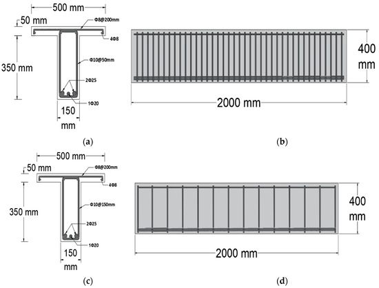
Figure 1.
Beams geometry: (a) cross section of group (A); (b) longitudinal section of group (A); (c) cross section of group (B); (d) longitudinal section of group (B).
2.3. Details of Specimens
As mentioned earlier, the specimens were divided into groups (A) and (B) according to the internal shear stirrup spacing used. Group A reinforced with internal stirrups of Φ10@50 mm consists of four beams: one control beam with no NSM-CFRP as a control beam for comparison; two strengthened beams with NSM-CFRP strips attached in an inclination of 45° and spacing at 75 and 150 mm; and one rehabilitated beam loaded up to 60% of its capacity before attaching the NSM-CFRP strips in an inclination of 45° and at a spacing of 75 mm. Group B reinforced with internal stirrups of Φ10@150 mm consists of four beams: one control beam with no NSM-CFRP as a control beam for comparison; one strengthened beam with NSM-CFRP attached in an inclination of 45° and at a spacing of 75 mm; and two rehabilitated beams loaded up to 60% of their capacity before attaching the NSM-CFRP in an inclination of 45° and at spacings of 75 and 150 mm. The inclination of 45° is adopted in this study because it was reported in the literature that this inclination provided the best results among other inclinations [39,40,41]. Figure 2 illustrates the details of NSM-CFRP configurations.
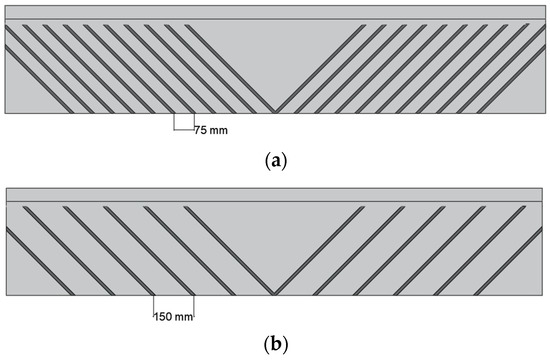
Figure 2.
Details of CFRP configurations: (a) beams with 75 mm carbon spacing; (b) beams with 150 mm carbon spacing.
Beams are named in order of (group symbol—strengthening or rehabilitating with the spacing of the NSM-CFRP). For the first term, A is designated for group A, B is for group B, and C is for the control beam. For the second term, S is designated for strengthening, and R is for rehabilitating. For the third term, 75 and 150 are for NSM-CFRP strip spacing of 75 and 150 mm, respectively. For example, specimen B-R75 refers to a beam from group B, rehabilitated by loading up to 60% of its capacity before attaching the NSM-CFRP at a spacing of 75 mm. Table 3 provides an illustration of all specimens used.

Table 3.
Details of Specimens.
2.4. Construction of Beams
2.4.1. Concrete Casting and Curing
Steel reinforcement was prepared and tied together using steel wires. The main reinforcement steel was then placed in a steel mold made of 6 mm steel sheets that were welded together to obtain a T-shape mold. Stiffeners were used and fixed along the mold length to avoid any local buckling that might occur during concrete pouring. After the molds were removed, a smooth surface was obtained with no treatment needed. Six cubes were also cast to determine the actual compressive strength of the concrete at 28 days of casting.
2.4.2. CFRP Installation
Several grooves of 20 mm width and 8 mm thickness were made using an electric saw at their predefined locations. The grooves were then cleaned from the dust using an air blower to ensure that the epoxy bonded perfectly with the concrete. The epoxy was mixed in specific proportions as recommended by the manufacturer to achieve the best strength. Specimens were tested after 7 days after installing the carbon fiber to provide enough time for the epoxy to harden and reach its strength. Figure 3 shows the preparation of the grooves.
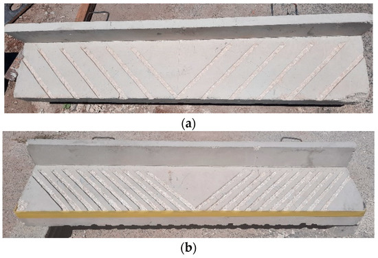
Figure 3.
Preparation of grooves for: (a) 150 mm spacing; (b) 75 mm spacing.
2.5. Test Setup
A three-point loading test was conducted using a 700 kN MFL Prüf-systeme Universal Testing Machine. All beams were placed on two steel rods located at 100 mm from both ends of the beam; hence, the beams were treated as simply supported ones. The deflection of the beams was measured using a dial gage placed at the mid span. The tests were performed under load control. The load was applied at a constant rate of 10 kN/min increments. Figure 4 shows the test setup of this study.
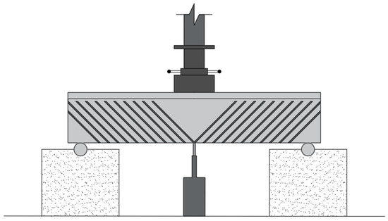
Figure 4.
Test Setup.
3. Theoretical Capacity According to the ACI 440.2R-17 [45]
The ACI 440.2R-17 [45] was used to predict the shear capacity for all beams. The code obtains the shear capacity by adding the contributions of the concrete, steel, and the CFRP altogether. The ACI 440.2R-17 defines the theoretical shear capacity by the equation:
where is a reduction factor (equals to 0.75 for shear calculations), Vn is the nominal shear strength of the beam, Vc is the nominal shear strength provided by concrete with steel flexural reinforcement, Vs is the nominal shear strength provided by steel stirrups, is a strength reduction factor for CFRP, and Vf is the nominal shear strength provided by CFRP.
The ACI 440.2R-17 refers to the ACI 318-19 [46] when calculating the terms Vc and Vs.
4. Results and Discussion
4.1. General Behavior and Failure Modes
All beams failed in shear as anticipated. Flexural hair cracks started to appear at the mid span of the beams while the load was between 40 and 50 kN. After that, shear cracks started to appear near the supports where there was no NSM-CFRP strips attached. However, the crack propagation was hard to notice and track during the test due to the existence of the NSM-CFRP and epoxy resin with small spacings. Near the failure, the flexural cracks started to get wider and propagated vertically. In addition, flange and concrete side cover separation started to happen at the edges. When the load was increased up to failure, the flange collapsed in some beams, and the concrete side cover separated from the beam. It should be noted that no NSM-CFRP de-bonding or rupture was observed during the test. However, the epoxy resin cracked in some places. After the concrete cover was removed, shear cracks were noticed behind the NSM-CFRP strips that extended from near the support up to the loading point. Figure 5 and Figure 6 illustrate the failure mode of groups A and B, respectively.
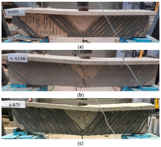
Figure 5.
Failure modes of group A specimens. (a) A-S75 (b) A-S150 (c) A-R75.
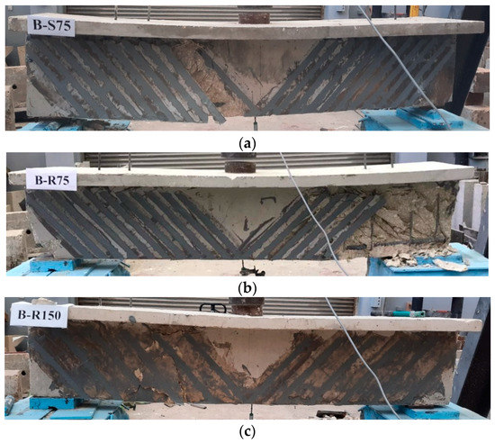
Figure 6.
Failure modes of group B specimens. (a) B-S75 (b) B-R75 (c) B-R150.
4.2. Experimental Load–Deflection Behavior
Figure 7a,b show the experimental load–deflection curves for all tested beams for groups A and B, respectively. It can be noted that all beams strengthened or rehabilitated with NSM-CFRP showed higher deflections than their corresponding control samples. Moreover, it can be seen that the beams rehabilitated with NSM-CFRP showed higher deflection with small increments in the load near the failure.
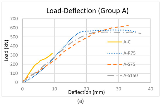
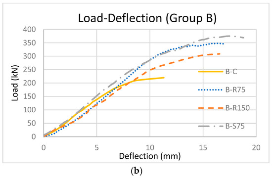
Figure 7.
Experimental load–deflection curves for: (a) group A; (b) group B.
Figure 8 illustrates the deflection of all beams along their length. All the beams with NSM-CFRP showed higher deflection values than all the control beams in all groups. This is an indication that using NSM-CFRP strips for strengthening or rehabilitating processes increased the ductility of beams. Moreover, it can be noticed that group A beams showed higher deflection values than group B beams.
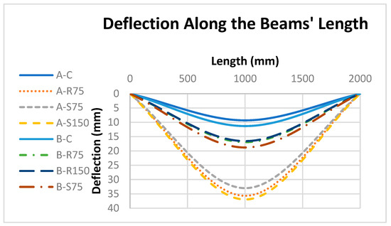
Figure 8.
Deflection along the beam length.
Accordingly, it can be stated clearly that using NSM-CFRP improved the ductility of the beams and enhanced the deflection compared to the control beams that did not use NSM-CFRP.
4.3. Experimental Ultimate Loads
Table 4 shows the experimental ultimate load capacities for all specimens.

Table 4.
Experimental Load Results.
All beams in both groups, strengthened and rehabilitated, reached higher failure loads than their corresponding control beams. For group A, the use of NSM-CFRP enhanced the capacities by 73% to 95% compared to the control beam A-C, while for group B, the enhancement was in the range of 40% to 71%.
For the beams strengthened in group A, the shear capacity increased with the decrease in the spacing between the NSM-CFRP strips, i.e., beam A-S75 recorded a capacity 95% higher than the control beam, whereas beam A-S150 recorded an enhancement of 73%. This agrees well with the results of Saadah et al. [41] as they concluded that the strength increased by decreasing the spacing between the NSM-CFRP strips. Additionally, for the beams strengthened in group B, the shear capacity increased with the decrease in the spacing between the NSM-CFRP strips, i.e., beam B-R75 recorded a capacity 58% higher than the control beam, whereas beam B-R150 recorded an enhancement of 40%.
Additionally, it can be noticed that the strengthened beams showed higher shear capacities than the rehabilitated beams with the same NSM-CFRP strip spacing regardless of the internal stirrup spacing. For group A, the beam A-S75 recorded an enhancement of 95%, while the beam A-R75 reached a capacity 80% higher than the control beam. This is also observed in group B by comparing the samples B-S75 and B-R75, in which an enhancement of 71% and 58% was recorded for both beams, respectively. This does not agree with the findings of Jayaprakash et al. [32] as the authors stated that precracked-repaired beams achieved better performance compared to the initially strengthened beams. The reason behind that could be attributed to the fact that the rehabilitated beams were loaded up then the NSM-CFRP was added to the beams. The loading up affected the whole strength of the beams and weakened them compared to the strengthened beams that were not loaded up. Accordingly, it is expected that the enhancements in the shear strength will be better in the strengthened beams compared to the rehabilitated beams as the experimental results revealed.
From Table 4, and by comparing the beams across groups, it is concluded that the enhancement in shear capacity increased by decreasing the spacing of the internal shear stirrups for control, strengthened, and rehabilitated beams. The percent enhancement for beams in group A is around 22% higher than their corresponding beams in group B. This is clearly seen by comparing the beam A-R75 with B-R75, and the beam A-S75 with B-S75, in which for both cases the capacities of beams in group A are higher than the beams in group B. This can be attributed to the fact that the steel stirrups interrupt the shear cracks and delay the failure; thus, by increasing the number of steel stirrups, i.e., decreasing the spacing between the stirrups, the shear capacity increases.
These results showed clearly that using NSM-CFRP improves the shear capacity of the beams whether strengthened or rehabilitated and regardless of the transverse reinforcements inside the beams. Additionally, it was noticed that no de-bonding or rupture was observed at failure which makes this technique more attractive than using external CFRP.
4.4. Theoretical Results
The ACI 440.2R-17 [45] was used to predict the theoretical capacity for all beams. Table 5 provides a comparison between the experimental and theoretical results.

Table 5.
Experimental and Theoretical Capacity Results.
The ACI 440.2R-17 [45] predicted lower shear capacities than the experimental ones for both groups. The difference between the experimental and theoretical results increased with the decrease in the internal stirrup spacing. For the beams strengthened or rehabilitated by NSM-CFRP strips, the experimental results were higher than the theoretical capacities by a range of (35% to 40%) and (22% to 28%) for groups A and B, respectively.
The ACI 440.2R-17 [45] does not consider the effect of preloading of beams in the rehabilitation process and deals with it the same as the strengthening process. Thus, the theoretical capacities are the same for the beams strengthened or rehabilitated using NSM-CFRP. However, this does not agree with the experimental results as the beams strengthened with NSM-CFRP reached higher capacities than their corresponding beams rehabilitated with the same NSM-CFRP scheme because the loading up in the rehabilitated beams affected the whole strength of the beams and weakened them compared to the strengthened beams that were not loaded up.
In general, the ACI 440.2R-17 code [45] was conservative in predicting the theoretical shear capacities.
5. Conclusions
This study presents an experimental and analytical investigation of strengthening and rehabilitating RC T-beams with different NSM-CFRP configurations for different internal stirrup spacing. From this study, it can be concluded that:
- Regardless of the internal shear stirrup spacing, all beams exhibited pure shear failure in which the dominated failure mode was side concrete cover separation with shear cracks propagated behind the NSM-CFRP from near the supports up to the loading point. The flange collapsed in some beams; however, no NSM-CFRP de-bonding or rupture was noticed.
- The use of NSM-CFRP enhanced the shear capacities for all beams in the range of 40% to 95%. However, the enhancement in the strengthened beams was higher than that in the rehabilitated beams with the same NSM-CFRP scheme.
- The shear capacity increased with the decrease in the internal stirrup spacing and NSM-CFRP strip spacing.
- The ACI 440.2R-17 code was found to be conservative in predicting the theoretical shear capacity of the beams using NSM-CFRP inclined strips. However, the code does not distinguish between the strengthening and rehabilitating of beams.
The results showed clearly that the NSM-CFRP technique was very promising in improving the shear strength of strengthened and rehabilitated beams regardless of the number of transverse reinforcements used inside beams, and the de-bonding or rupture of NSM-CFRP was not noticed. This could be considered the main significance of the research work since most of the time the external CFRP would de-bond or rupture at failure.
Author Contributions
Conceptualization, M.A.-J. (Mu’tasim Abdel-Jaber); methodology, H.K.; validation, N.S.; formal analysis, M.A.-J. (Ma’en Abdel-Jaber); investigation, R.E.-N. and A.S.; resources, M.A.-J. (Mu’tasim Abdel-Jaber); data curation, A.S. and R.E.-N.; writing—original draft preparation, R.E.-N.; writing—review and editing, H.K.; visualization, H.K. and N.S.; supervision, M.A.-J. (Ma’en Abdel-Jaber); project administration, M.A.-J. (Mu’tasim Abdel-Jaber). All authors have read and agreed to the published version of the manuscript.
Funding
This research received no external funding.
Data Availability Statement
The article includes all the research data.
Conflicts of Interest
The authors declare no conflict of interest.
References
- Zhang, Z.; Hsu, C.T. Shear Strengthening of Reinforced Concrete Beams Using Carbon-Fiber-Reinforced Polymer Laminates. J. Compos. Constr. 2005, 9, 158–169. [Google Scholar] [CrossRef]
- Dong, J.; Wang, Q.; Guan, Z. Structural Behavior of RC Beams with External Flexural and Flexural–Shear Strengthening by FRP Sheets. Compos. Part B 2013, 44, 604–612. [Google Scholar] [CrossRef]
- Hassan, S.K.H.; Abdel-Jaber, M.S.; Alqam, M. Rehabilitation of Reinforced Concrete Deep Beams Using Carbon Fiber Reinforced Polymers (CFRP). Mod. Appl. Sci. 2018, 12, 179–194. [Google Scholar] [CrossRef]
- Abed, D.J.; Abdel- Jaber, M.S.; Shatarat, N.K. Behavior of Square Reinforced- Concrete Columns Strengthened with Carbon Fiber Reinforced Polymers (Cfrp) Under Eccentric Loading. Int. J. Civ. Eng. Technol. 2018, 9, 532–547. [Google Scholar]
- Al-Zu’Bi, H.; Abdel-Jaber, M.; Katkhuda, H. Flexural Strengthening of Reinforced Concrete Beams with Variable Compressive Strength Using Near-Surface Mounted Carbon-Fiber-Reinforced Polymer Strips [NSM-CFRP]. Fibers 2022, 10, 86. [Google Scholar] [CrossRef]
- Abdel Hafez, A.M. Shear Behavior of RC Beams Strengthened Externally with Bonded CFRP–U Strips. J. Eng. Sci. 2007, 35, 361–379. [Google Scholar] [CrossRef]
- Abdel-Jaber, M.S.; Walker, P.R.; Hutchinson, A.R. Shear Strengthening of Reinforced Concrete Beams Using Different Configurations of Externally Bonded Carbon Fibre Reinforced Plates. Mater. Struct. 2003, 36, 291–301. [Google Scholar] [CrossRef]
- Abdel-Jaber, M. Shear Strengthening of Reinforced Concrete Beams Using Externally Bonded Carbon Fibre Reinforced Plates. Ph.D. Thesis, Oxford Brookes University, Oxford, UK, 2001. [Google Scholar]
- Abdel-Jaber, M.; Shatanawi, A.S.; Abdel-Jaber, M.S. Guidelines for Shear Strengthening of Beams Using Carbon Fiber-Reinforced Polymer (FRP) Plates. Jordan J. Civ. Eng. 2007, 1, 327–335. [Google Scholar]
- Adhikary, B.B.; Mutsuyoshi, H. Shear Strengthening of Reinforced Concrete Beams Using Various Techniques. Constr. Build. Mater. 2006, 20, 366–373. [Google Scholar] [CrossRef]
- Al-Ghanim HAl-Asi AAbdel-Jaber, M.; Alqam, M. Shear and Flexural Behavior of Reinforced Concrete Deep Beams Strengthened with CFRP Composites. Mod. Appl. Sci. 2017, 10, 110–122. [Google Scholar]
- Alsayed, S.H.; Siddiqui, N.A. Reliability of Shear-Deficient RC Beams Strengthened with CFRP-Strips. Constr. Build. Mater. 2013, 42, 238–247. [Google Scholar] [CrossRef]
- Alsayed, S.H. Effect of Fiber Parameters and Concrete Strength on Shear Behavior of Strengthened RC Beams. Constr. Build. Mater. 2013, 44, 15–24. [Google Scholar]
- Barros, J.A.; Dias, S.J.; Lima, J.L. Efficacy of CFRP-based Techniques for the Flexural and Shear Strengthening of Concrete Beams. Cem. Concr. Compos. 2007, 29, 203–217. [Google Scholar]
- Bousselham, A.; Chaallal, O. Shear Strengthening Reinforced Concrete Beams with Fiber-Reinforced Polymer: Assessment of Influencing Parameters and Required Research. ACI Struct. J. 2004, 101, 219–227. [Google Scholar]
- Bukhari, I.; Vollum, R.; Ahmad, S.; Sagaseta, J. Shear Strengthening of Reinforced Concrete beams with CFRP. Mag. Concr. Res. 2010, 62, 65–77. [Google Scholar] [CrossRef]
- Chajes, M.J.; Januska, T.F.; Mertz, D.R.; Thomson, T.A.; Finch, W.W. Shear Strengthening of Reinforced Concrete Beams Using Externally Applied Composite Fabrics. ACI Struct. J. 1995, 92, 295–303. [Google Scholar]
- Chen, J.F.; Tengb, J.G. Shear Capacity of FRP-Strengthened RC Beams: FRP Debonding. Constr. Build. Mater. 2003, 17, 27–41. [Google Scholar] [CrossRef]
- Godat, A.; Qu, Z.; Lu, Z.X.; Labossiere, P.; Ye, L.P.; Neale, K.W. Size Effects for Reinforced Concrete Beams Strengthened in Shear with CFRP Strips. J. Compos. Constr. 2010, 14, 260–271. [Google Scholar] [CrossRef]
- Ibrahim, A.M.; Mansor, A.A.; Hameed, M. Structural Behavior of Strengthened RC Beams in Shear using CFRP Strips. Open Civ. Eng. J. 2017, 11, 205–215. [Google Scholar] [CrossRef]
- Mhanna, H.H.; Hawilehb, R.A.; Abdallac, J.A. Shear Strengthening of Reinforced Concrete Beams Using CFRP Wraps. Procedia Struct. Integr. 2019, 17, 214–221. [Google Scholar] [CrossRef]
- Mostofinejad, D.; Hosseini, S.A.; Razavi, S.B. Influence of Different Bonding and Wrapping Techniques on Performance of Beams Strengthened in Shear Using CFRP Reinforcement. Constr. Build. Mater. 2016, 116, 310–320. [Google Scholar] [CrossRef]
- Teng, J.G.; Smith, S.T.; Yao, J.; Chen, J.F. Intermediate Crack-induced De-bonding in RC Beams and Slabs. Constr. Build. Mater. 2003, 17, 447–462. [Google Scholar] [CrossRef]
- Triantafillou, T. Shear Strengthening of Reinforced Concrete Beams Using Epoxy-Bonded FRP Composites. ACI Struct. J. 1998, 95, 107–115. [Google Scholar]
- Imran MShafiq, N.; Akbar, I. Strengthening Techniques & Failure Modes of RC Beam Strengthened Using Fibre Reinforced Polymer. A Review. GSTF J. Eng. Technol. 2013, 2, 93–98. [Google Scholar]
- Bae, W.; Belarbi, A.; Brancaccio, A. Shear strengthening of full-scale RC T-Beams using externally bonded CFRP sheets. In Proceedings of the First Middle East Conference on Smart Monitoring, Assessment and Rehabilitation of Civil Structures, Dubai, United Arab Emirates, 8–10 February 2011. [Google Scholar]
- Kim, Y.; Quinn, K.; Ghannoum, W.M.; Jirsa, J.O. Strengthening of Reinforced Concrete T-Beams Using Anchored CFRP Materials. ACI Struct. J. 2012, 111, 1027. [Google Scholar] [CrossRef]
- Soliman, J. General behavior of T–section RC beams strengthened with epoxy–bonded carbon strands. MOJ Civil Eng. 2018, 4, 213–217. [Google Scholar] [CrossRef]
- El-Saikaly, G.; Godat, A.; Chaall, O. New Anchorage Technique for FRP Shear-Strengthened RC T-Beams Using CFRP Rope. J. Compos. Constr. 2015, 19, 04014064. [Google Scholar] [CrossRef]
- Tanarslan, H.M.; Altin, S. Behavior of RC T-section beams strengthened with CFRP strips, subjected to cyclic load. Mater. Struct. 2009, 43, 529–542. [Google Scholar] [CrossRef]
- Khalifa, A.; Nanni, A. Improving shear capacity of existing RC T-section beams using CFRP composites. Cem. Concr. Compos. 2000, 22, 165–174. [Google Scholar] [CrossRef]
- Jayaprakash, J.; Samad, A.A.; Ashrabov, A.A.; Chong, K.K. Experimental Investigation on Shear Resistance Behaviour of RC Precracked and Non Precracked T-Beams using Discrete CFRP Strips. Int. J. Integr. Eng. 2009, 1, 1–5. [Google Scholar]
- Williams, B.; Kodur, V.; Green, M.F.; Bisby, L. Fire Endurance of Fiber-Reinforced Polymer Strengthened Concrete T-Beams. ACI Struct. J. 2009, 105, 60–67. [Google Scholar]
- Rosa, I.C.; Firmo, J.P.; Correia, J.R.; Mazzuca, P. Influence of elevated temperatures on the bond behaviour of GFRP bars to concrete—Pull-out tests. In Proceedings of the IABSE Symposium 2019 Guimarães: Towards a Resilient Built Environment—Risk and Asset Management, Guimarães, Portugal, 27–29 March 2019. [Google Scholar]
- Darain, K.M.; Jumaat, M.Z.; Shukri, A.A.; Obaydullah, M.; Huda, M.N.; Hosen, M.A.; Hoque, N. Strengthening of RC Beams Using Externally Bonded Reinforcement Combined with Near-Surface Mounted Technique. Polymers 2016, 8, 261. [Google Scholar] [CrossRef] [PubMed]
- De Lorenzis, L.; Teng, J.G. Near-Surface Mounted FRP Reinforcement: An emerging technique for strengthening structures. Compos. Part B 2007, 38, 119–143. [Google Scholar] [CrossRef]
- Rizzo, A.; De Lorenzis, L. Behavior and capacity of RC beams strengthened in shear with NSM FRP reinforcement. Constr. Build. Mater. 2009, 23, 1555–1567. [Google Scholar] [CrossRef]
- Sena-Cruz, J.M.; Barros, J.A.O. Bond between near-surface mounted CFRP laminate strips and concrete. J. Compos. Constr. ASCE 2004, 8, 519–527. [Google Scholar] [CrossRef]
- Dias, S.; Barros, J. Performance of reinforced concrete T beams strengthened in shear with NSM CFRP laminates. Eng. Struct. 2010, 32, 373–384. [Google Scholar] [CrossRef]
- Al Rjoub, Y.S.; Ashteyat, A.M.; Obaidat, Y.T.; Bani-Youniss, S. Shear strengthening of RC beams using near-surface mountedcarbon fibre-reinforced polymers. Aust. J. Struct. Eng. 2019, 20, 54–62. [Google Scholar] [CrossRef]
- Saadah, M.; Ashteyat, A.; Murad, Y. Shear strengthening of RC beams using side near surface mounted CFRP ropes and strips. Structures 2021, 32, 380–390. [Google Scholar] [CrossRef]
- Abdel-Jaber, M.; Abdel-Jaber, M.; Katkhuda, H.; Shatarat, N.; El-Nimri, R. Influence of Compressive Strength of Concrete on Shear Strengthening of Reinforced Concrete Beams with Near Surface Mounted Carbon Fiber-Reinforced Polymer. Buildings 2021, 11, 563. [Google Scholar] [CrossRef]
- Ebead, U.; Wakjira, T.G. Behaviour of RC beams strengthened in shear using near surface embedded FRCM. IOP Conf. Ser. Mater. Sci. Eng. 2018, 431, 072001. [Google Scholar] [CrossRef]
- Bencardino, F.; Nisticò, M. A Theoretical Model for Debonding Prediction in the RC Beams Externally Strengthened with Steel Strip and Inorganic Matrix. Materials 2021, 14, 4961. [Google Scholar] [CrossRef] [PubMed]
- Bakis, C.E.; Ganjehlou, A.; Kachlakev, D.I.; Schupack, M.; Balaguru, P.; Gee, D.J.; Karbhari, V.M.; Scott, D.W.; Ballinger, C.A.; Gentry, T.R.; et al. ACI 440.2R-17: Guide for the Design and Construction of Externally Bonded FRP Systems for Strengthening Concrete Structures; ACI Committee: Farmington Hills, MI, USA, 2017. [Google Scholar]
- American Concrete Institute. Building Code Requirements for Reinforced Concrete and Commentary; ACI 318: 318M–19; American Concrete Institute: Indianapolis, IN, USA, 2019; p. 261. [Google Scholar]
Publisher’s Note: MDPI stays neutral with regard to jurisdictional claims in published maps and institutional affiliations. |
© 2022 by the authors. Licensee MDPI, Basel, Switzerland. This article is an open access article distributed under the terms and conditions of the Creative Commons Attribution (CC BY) license (https://creativecommons.org/licenses/by/4.0/).