Article

Flexural Strengthening of Reinforced Concrete Beams with Variable Compressive Strength Using Near-Surface Mounted Carbon-Fiber-Reinforced Polymer Strips [NSM-CFRP]

by
Hebah Al-zu’bi
2,
Mu’tasim Abdel-Jaber
1,2,*,† and
Hasan Katkhuda
3
1
Faculty of Engineering, Department of Civil Engineering, Al-Ahliyya Amman University, Amman 19328, Jordan
2
Faculty of Engineering, Department of Civil Engineering, The University of Jordan, Amman 11942, Jordan
3
Faculty of Engineering, Department of Civil Engineering, The Hashemite University, Zarqa 13133, Jordan
*
Author to whom correspondence should be addressed.
On sabbatical leave from Department of Civil Engineering, The University of Jordan, Amman 11942, Jordan.
Fibers 2022, 10(10), 86; https://doi.org/10.3390/fib10100086
Submission received: 12 September 2022 / Revised: 7 October 2022 / Accepted: 10 October 2022 / Published: 13 October 2022

Abstract

:
An experimental and analytical investigation was conducted on reinforced concrete (RC) beams strengthened in flexure using the near-surface mounted carbon-fiber-reinforced polymers (NSM-CFRPs) technique. A total of 11 full-scale RC rectangular beams were cast and tested under a monotonic three-point bending test, up to failure. The main test variables adopted in this study were the concrete compressive strength (high, medium, and low), the number of CFRP strips, and the strip length. The results indicated that the use of NSM-CFRPs strips in different configurations efficiently increased the load-carrying capacity of the strengthened RC beams, in which all these beams exhibited a higher moment resistance than the corresponding un-strengthened beam. Results also showed that all strengthening schemes were successful in increasing the flexural capacity of the specimens tested. Such increases ranged between 10.36% and 52.28%. Notably, a significant improvement in the ultimate load ratio was observed with beams having a low compressive strength of 17-MPa, then followed by the beams with medium strength (32-MPa), and finally beams with high compressive strength (47-MPa). The NSM technique reduced the occurrence possibility of the CFRP de-bonding failure mode. Furthermore, the test results were compared with theoretical predictions using the ACI 440.2R17 guidelines and showed a good agreement between these results.

1. Introduction

Due to its high durability, fire resistance, and ability to resist weather conditions, concrete is considered a widely used material in building reinforced-concrete (RC) structures. However, with the massive increase in the RC structure construction and the increase in their lifespans, it is expected that these structures will deteriorate over time because of the exposure to several natural effects such as high-temperature conditions, humidity, chemical attacks, and additional loadings. Moreover, RC members in the structures could fail due to human-made errors such as design errors, poor maintenance, increases in live loads caused by the change in the facility type, and wars or terrorist attacks [1,2,3,4].
It is difficult to demolish and rebuild the damaged buildings due to their high costs, long durations for completion, and physical efforts. Therefore, the strengthening and rehabilitation process was introduced through different methods to ensure that the required strength is achieved and the service life of a structure is, in turn, extended. Furthermore, strengthening the deteriorated RC slabs, beams, columns, and bridges has become a prime approach to meet the updated design codes and achieve the strength requirements [5,6,7,8,9,10,11,12,13,14]. Thus, the overall goals of strengthening techniques are to enhance the structure behavior by improving the flexural or shear capacity, ductility behavior, and durability under different loading conditions, thereby extending their service life. Nowadays, experts pay increasing attention to RC structures and develop advanced solutions for their strengthening and retrofitting [15,16,17].
Fiber reinforcement polymers (FRP) were considered one of the most popular strengthening materials, which can withstand conditions and provide good enhancement results. Various fiber types were used in the RC structure strengthening systems, such as carbon, glass, aramid, and basalt fibers [18,19,20]. The use of FRPs material has grown over the past decades because of its exceptional features such as its light weight, high strength, non-corrosive nature, excellent fatigue response, and installation simplicity [15,16,21,22,23].
Several techniques were investigated in strengthening and rehabilitating using FRPs composites. The external-bonded technique (EB) and near-surface-mounted (NSM) technique were viewed as the promising strengthening systems since they improve the shear and flexural capacity of the RC structures. To this end, numerous research studies have been performed on RC members’ strengthening using externally bonding fiber-reinforced polymers (EB-FRPs) materials laminates and sheets [24,25,26,27,28,29,30,31]. This technique has been introduced in a variety of practical worldwide projects. The base of the EB-FRPs technique is to affix the FRPs to the external concrete surface of RC members using a proper adhesive [32,33]. In spite of the commonness of this technique, de-bonding failure occurs out of the concrete surface at a low strain level of the FRPs. That means the system’s ultimate strength is not yet reached. The EB, additionally, needs extensive work implementation on-site, such as plaster removal. Additionally, FRPs are, however, unprotected from exposure to environmental conditions. More recently, and because of the earlier-mentioned EB drawbacks, the NSM reinforcement using FRPs bars/strips has been an attractive appropriate alternative technique [34,35,36,37,38,39,40].
Near-surface-mounted reinforcement (NSM), also called “embedded reinforcement” or “grout reinforcement” [41], is among the most cutting-edge and attractive strengthening systems for RC structures. NSM was developed in the early 1950s in Europe, particularly in Sweden, where it was used to strengthen a concrete bridge using embedded steel bars. This technique implies placing strengthening materials into grooves previously formed into the concrete cover and then bonded with a suitable bonding agent, typically using epoxy adhesives or cement grout as filler. According to the literature, these strengthening materials studied were in the form of bars or strips (rectangular bars). Although this technique requires extra work for groove formation, it proved its effectiveness in protecting the RC structures from the previously mentioned deterioration factors [1,42]. Additionally, the NSM-FRPs system has several advantages over the EB-FRPs system, for instance, (a) minimizing the site implementation works other than groove preparation; (b) the FRPs are attached inside the concrete and then covered with epoxy, which contributes to protecting FRPs from environmental influences and vandalism; and (c) it is less prone to separation from the concrete surface (de-bonding failure) [34,35,36,37,38].
Recently, Abdel-Jaber et al. [8] investigated experimentally and analytically the effect of using NSM-CFRP on the shear behavior of rectangular RC beams having different compressive strengths (low, medium, and high). A total of 12 simply-supported RC beams were strengthened using NSM-CFRP technique in different configurations and then tested under monotonic three-point loading until failure. The test results demonstrated the effectiveness of using the NSM-CFRP strips as a strengthening technique in enhancing the beams shear capacity by 4% to 66%. Moreover, the investigation concluded that when the compressive strengths increase, the shear capacities also increase for all beams. On the other hand, the failure mode was confined to pure-shear failure in all beams without rupture or de-bonding in the CFRP strips. More importantly, the experimental results demonstrated a good agreement with the results from the finite element analysis and the ACI 440.2R-17 guidelines.
In 2016, Khalifa [43] experimentally investigated the flexural performance of RC beams strengthened using CFRP strips with the NSM and EBR techniques. Numbers of two and four CFRP strips distributed in one or two grooves were also studied. The study revealed that the ultimate load was increased when distributing the same amount of NSM-CFRPs strips in two grooves rather than one groove. Furthermore, increasing the strip number does not always imply an improvement in flexural strength, and more importantly, the NSM technique showed a better enhancement in the flexural capacity than the EBR, about 12% to 18%.
Similarly, Sharaky et al. [44] examined RC rectangular beams strengthened partially and fully-bonded lengths using the NSM-CFRP technique. The effect of FRP characteristics, and reinforcement bond length were investigated, and different shapes of FRP were used. The test results proved that the strengthening using NSM-FRP fully-bonded length had greater bearing capacity and stiffness than partially-bonded NSM-FRP, and the deflection for fully-bonded strengthened beams was lower than partially-bonded strengthened beams.
In this paper, the flexural capacity of 11 simply-supported rectangular RC beams was strengthened using NSM-CFRP strips in different arrangements: (1) two NSM-CFRP strips were used along the entire beam span, (2) NSM-CFRP two strips were extended along the middle half of the span at the area of the maximum moment, and (3) two NSM-CFRP strips were extended along the entire span length from support to support. This research is dealing with these types of arrangements for low, medium, and high concrete-compressive strength with constant reinforcement ratios 0.5 ρmax, where the practical design of most RC beams takes place, in order to simulate the real behavior. There was a lack of literature that investigated such criteria. Therefore, this combination of ideas that simulates reality has never been conducted before as per the author’s knowledge. In addition to that, the flexural capacity was predicted in accordance with the provisions of ACI 440.2R-17 [45], and then it was compared to the experimental results.

2. Materials and Methods

2.1. Material Properties

2.1.1. Concrete

In order to investigate the influence of varying compressive strength on the RC strengthened beams, three different normal-weight concrete mixes were designed to achieve three different compressive strengths; high compressive strength (Class H, 47 MPa), medium compressive strength (Class M, 32 MPa), and low compressive strength (Class L, 17 MPa). The compressive strengths were classified based on the range between each other. Since the 47 MPa is considered high compared to 17 MPa and the 32 MPa is considered in the middle between 17 MPa and 47 MPa. All batches were ready-mix concrete. Standard concrete cubes of 150 mm × 150 mm × 150 mm were taken from the concrete mixes to conduct the compressive strength after 28 days. A total of eighteen cubes, six for each batch were cured then tested. The average cylindrical compressive strength for class H, M, and L were 42.62 MPa, 31.55 MPa, and 15.62 MPa, respectively. Table 1 shows the component proportion used in each batch from the manufactured company.

2.1.2. Steel Reinforcement

The types of internal reinforcement steel in the experimental program were deformed steel bars with high yield strength grade 60 ksi. The average yield strength and ultimate strength for longitudinal reinforcement bars were 420 MPa and 680 MPa, respectively. For the transverse reinforcement bars, 10 mm diameter stirrups with average yield strength of 420 MPa were used.

2.1.3. Carbon-Fiber-Reinforced Polymer (CFRP) Strips

The type of CFRPs strip used in this experimental program was SikaCarboDur® S1.525. This material is characterized as a unidirectional and high-performance strengthening system. Table 2 provides the mechanical and physical properties of the NSM-CFRP strips as per the manufacturing company.

2.1.4. Epoxy Resin

Sikadur®-330 was the epoxy used to bond the NSM-CFRPs strip with the concrete. This epoxy has two-components: Part A (Resin-white) and Part B (Hardener-gray). These Two parts were blended together with a ratio of 4:1 by weight to produce a light grey composite mixture. Table 3 provides the properties of Sikadur®-330 resin.

2.2. Test Specimens

2.2.1. Test Matrix

Eleven simply supported RC beams were categorized into three main test groups based on three concrete classes: class H, class M, and class L that have compressive strengths of 47 MPa, 32 MPa, and 17 MPa, respectively. Eight beams were strengthened at the bottom face with NSM-CFRP strips utilizing various schemes, while three un-strengthened beams were considered as reference (control) specimens. Figure 1 shows the longitudinal details of the strengthened specimens.
Beam designation for the compressive strength was as follows: L for low-, M for medium-, and H for high-strength concrete. Unstrengthened beams (control) were referred to by the letter C., while for the NSM-strengthened beams, the letter S was taken as the second term. Lastly, the numbering order was given for each of the strengthening schemes. Table 4 summarizes the details of all the tested beams.

2.2.2. Beams Geometrical and Reinforcement Details

All specimens had a rectangular cross-section, with a total length of 2000 mm and a clear span length of 1800 mm. The depth of the beam was 300 mm, and the width was 200 mm. The beams were designed to fail in flexure. The reinforcement ratio was kept constant for all beams at 0.5 ρmax to simulate a real case where most of the RC beams are usually designed in practice with this ratio. The details of the steel reinforcements for each class of concrete are shown in Figure 2.

2.3. Beams Installation

2.3.1. Casting and Curing

The steel reinforcement was prepared and then tied well by tie wires. After molds were lubricated, the reinforcement steel cages were placed in their appropriate place while maintaining the concrete cover in all directions. The vibration of the concrete while pouring took place manually using a mechanical vibrator to avoid segregation. Finally, the surface was leveled and smoothed to remove the excess concrete. After 2 days, the formwork was removed. The specimens were cured in the air for 21 days after being treated in damp burlap for 7 days. Figure 3 shows the casting and curing process.

2.3.2. Installation of NSM-CFRP Strips

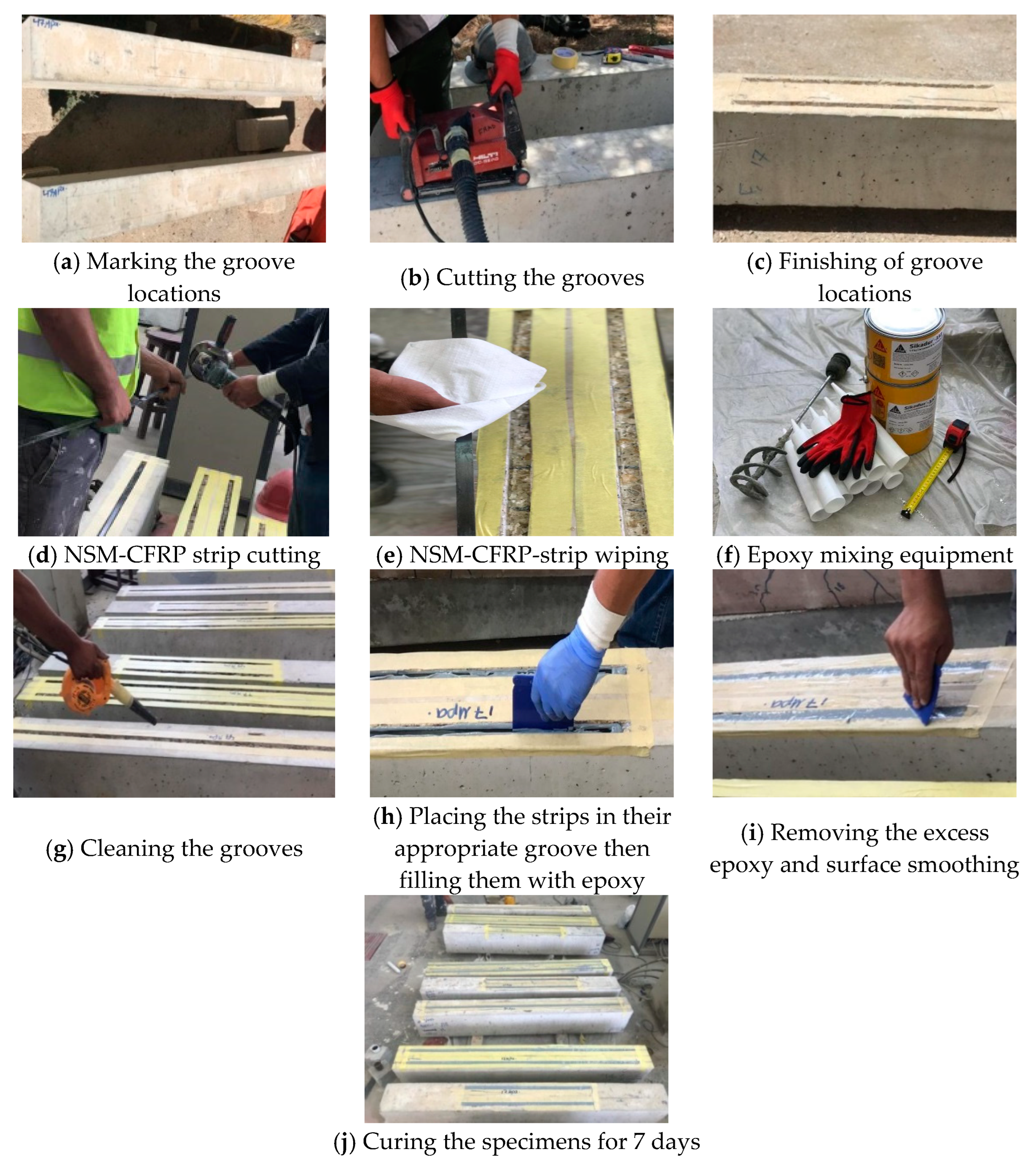
The locations of the grooves were marked on the beam’s soffit. These grooves were 8 mm in depth and 20 mm in width and cut by an electric saw. The grooves were further cleaned from dust, dirt, and particles scattered by a vacuum cleaner since the dust affects the bond between concrete and epoxy. Furthermore, the edges of these grooves were identified with sticky tape to facilitate control of the work area during fiber application. The CFRP strips were cut to their specific lengths and then wiped using a cotton cloth to clear dust and confirm a strong bond between carbon and epoxy. Afterward, Sikadur®-330 resin and the hardened parts were mixed for 3 min at slow speed until the mixture became smooth and a light gray color was uniform. The mix was then loaded into a disposable cartridge, and the grooves were filled with epoxy to about two-thirds using a mechanical tool. The strips were placed horizontally, fixed parallel to the tension reinforcement in their appropriate place, and covered with resin. Finally, the surface was smoothed, as the excess epoxy was removed through a scraper, then left to dry for 7 days to guarantee its full strength. Figure 4 shows the installation process of NSM-CFRP strips.

2.4. Test Setup

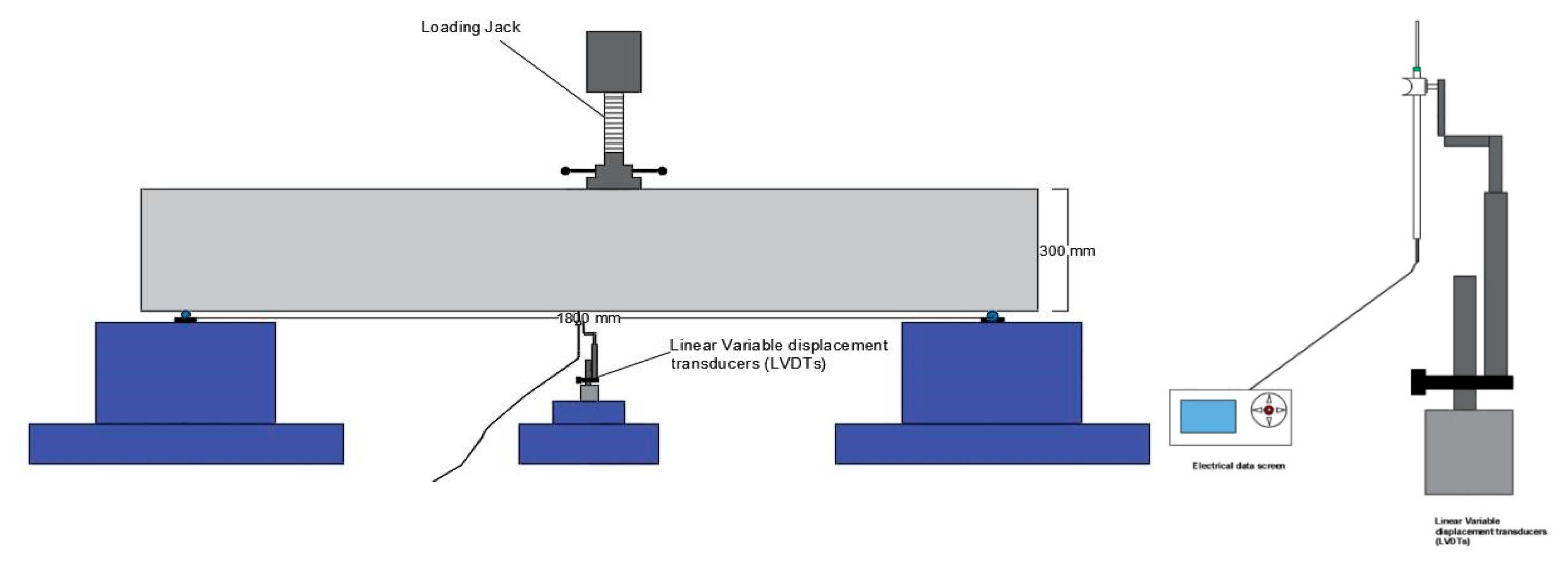
All beams were subjected to a monotonic three-point bending test up to failure. The test was carried out using a Universal Testing Machine (MFL Prüf-system) with 700-kN capacity. The load was applied at a constant rate of 10kN/min increment. The specimens were supported by a hinge at one end and a roller at the other with a 100 mm edge overhanging. Linear variable displacement transducers (LVDTs) device was fixed at the beam soffit in order to record the mid-span deflection during the test. The load-displacement readings were obtained from the electronic data screen. Figure 5 shows the test setup and LVDTs device.

3. Results and Discussion

3.1. Behavior and Failure Mechanisms

The unstrengthened beams (i.e., control beams) were utilized as a baseline for establishing the behavior of the strengthened beams using NSM-CFRPs strips. The propagation cracks on the concrete surface were monitored at each load increment and so was the vertical mid-span deflection. The initial flexural cracks for the control beams initiated from the tension area at the mid-span point and distributed up to the compression zone. Overall, the three strengthened schemes succeeded in improving the flexural capacity of the three groups with different percentages.
In such a manner, a considerable increase in the ultimate beam capacity was shown in the strengthened beams compared to their control beams between 7% and 52.28%. Table 5 illustrates the failure load, the corresponding vertical mid-span deflection, load enhancement ratio, and strength factor for all tested beams. The strengthened beams had an ultimate load capacity higher than the corresponding control beams as per the strength factor values. The strength-factor is the ratio between ultimate load capacities of the strengthened and the control beams.
For group H, all strengthened beams increased the ultimate beam capacity compared to the control beam CH by 7%, 10.72%, and 10.35% for (SH-1), (SH-2), and (SH-3), respectively. Figure 6 shows the load and deflection curves for all group specimens. The highest ultimate load achieved was with beams strengthened using two CFRPs strips extended along the middle half of the span (SH-2). Furthermore, the load-carrying capacity of the strengthening scheme by one CFRPs strip at the beam center extended at the entire span length (SH-3) was very near to that of (SH-2), and the difference between the SH-2 and SH-3 enhancement ratios was about 0.37%. Moreover, an increase in the vertical deflection was observed in beam specimens compared to the CH beam. This indicates that strengthening using CFRPs strips within this group enhanced the ductility behavior.
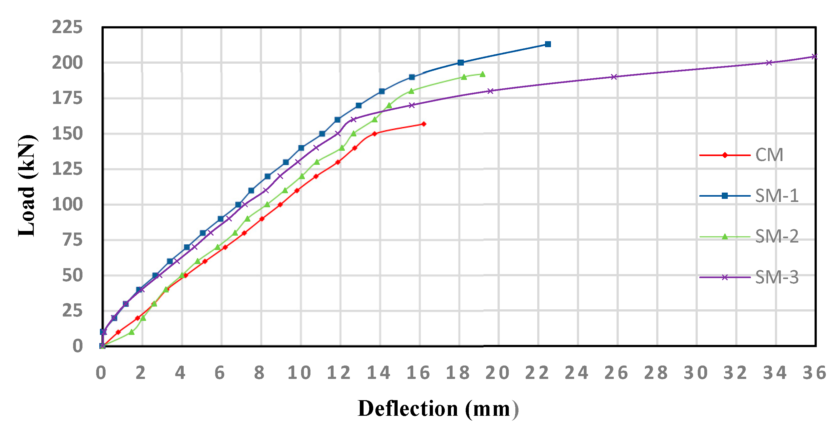
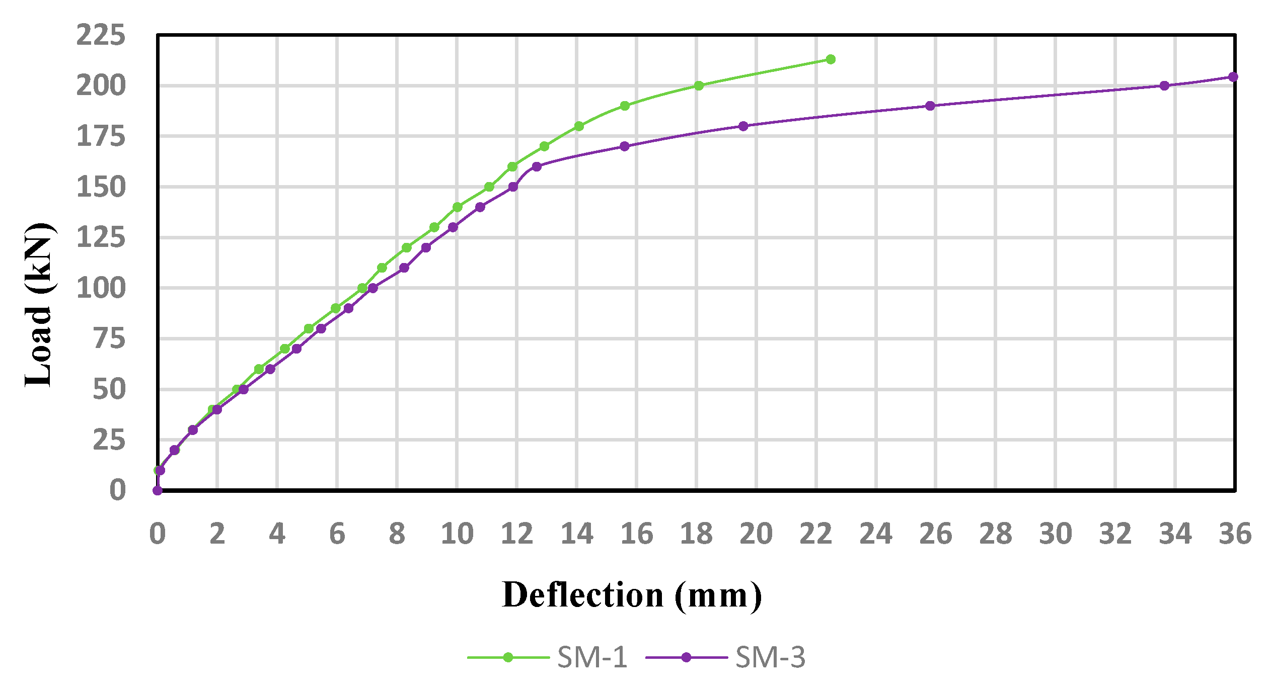
For group M, all strengthened beams showed a noticeable increase in the ultimate load capacity compared to the reference beam (CM) by 35.67%, 22.29%, and 30.0% for (SM-1), (SM-2), and (SM-3), respectively. Figure 7 shows the load and deflection curves for all group specimens. The highest ultimate load was achieved in specimen (SM-1), and thus it is considered the best-strengthened scheme within this group, followed by (SM-3), and finally (SM-2). Moreover, all beams showed an increase in the vertical deflection compared to the control beam (CM), thus, indicating that strengthening using CFRPs strips in this group enhanced the ductility behavior. (SM-3) showed the highest ductility behavior compared to all strengthened schemes.
All strengthened beams of group L showed an increase in their ultimate load capacity compared to the reference beam (CL) by 52.28% and 19.0% for (SL-1) and (SL-2), respectively. Figure 8 shows the load and deflection curves for all group specimens. The highest ultimate load was achieved in (SL-1), which was strengthened using two CFRPs strips along the entire beam span; accordingly, this scheme can be considered the best-strengthening scheme within this group, followed by beam (SL-2). Additionally, both strengthened beams indicated a significant ductile behavior with a considerable deflection value. Compared to the other NSM-strengthened beam, the (SL-1) specimen showed the highest ductility behavior.
Although the beams strengthened with one CFRPs strip showed higher ductility, the percentage enhancement in the ultimate load capacity was higher in the beams strengthened with two CFRPs strips at the full length. In this research study, the enhancement ratio was adopted as the main criterion to investigate the effectiveness of using the CFRPs scheme. Noteworthy that when the concrete compressive strength is increased, the enhancement percentage in the ultimate load decreased. Thereby, the enhancement range between different schemes at the same compressive strength is diminished.

3.2. Failure Modes

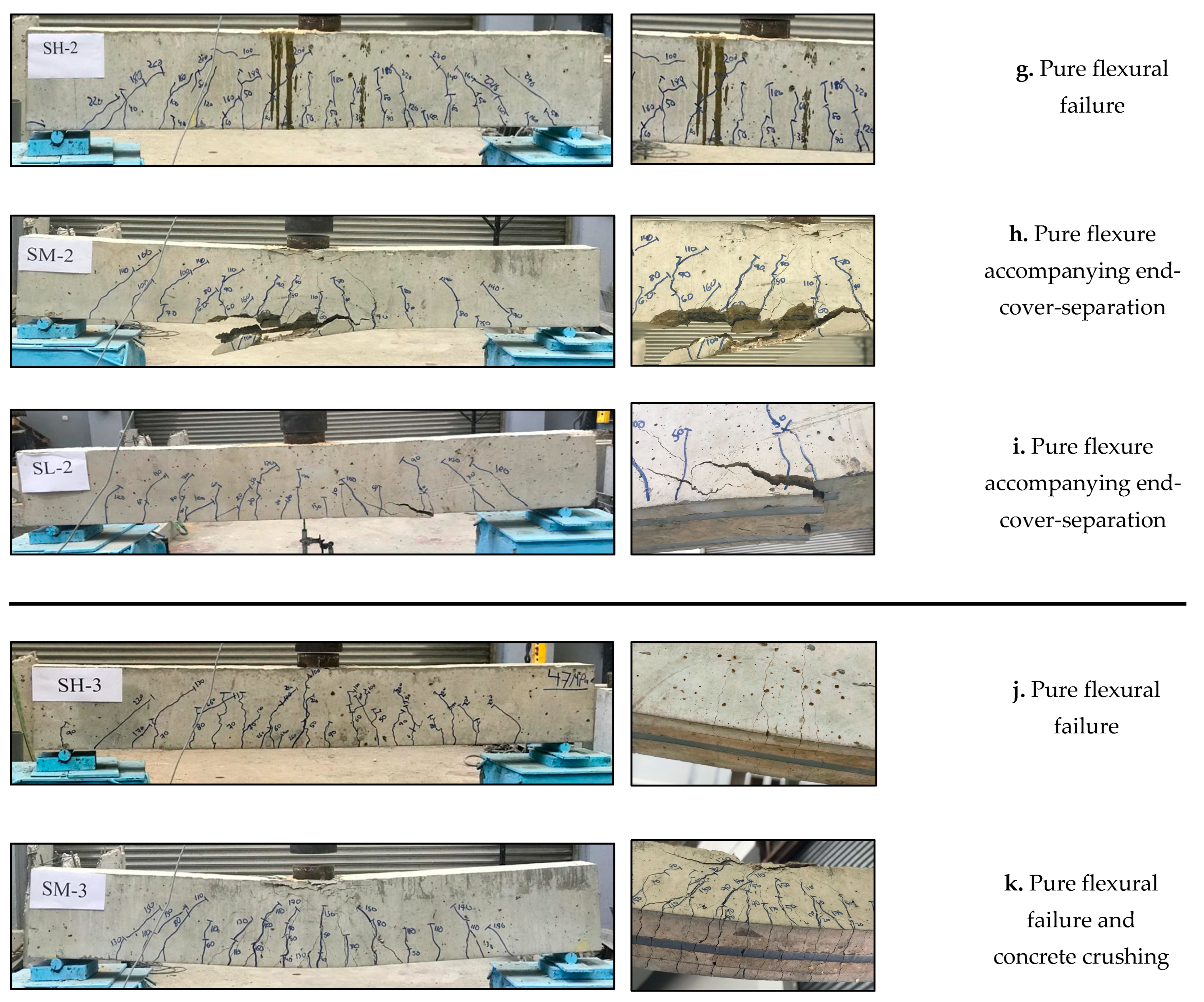
In this experimental program, different modes of failure were observed, namely, pure-flexural failure, concrete crushing, intermediate de-bonding and end-cover-separation resulting from NSM-CFRPs strips.
For the unstrengthened beams, as shown in Figure 9a–c, a pure flexural failure was the dominant failure mode accompanying crushing at the concrete’s top fiber for beams CH and CM, while it was a pure flexure failure in beam (CL).
Regarding the beams strengthened with two CFRPs strips along the entire beam span (SM-1 and SL-1), (SM-1) failed by pure flexure with an intermediate epoxy-de-bonding as shown in Figure 9d, while in Figure 9e, the failure mode for (SL-1) was pure-flexure only. Additionally, for specimens SH-1, it is worth mentioning that during NSM application, specifically while the grooves were cut and due to insufficient concrete cover in the bottom face of the beam, the stirrups legs were cut from both grooves sides in order to get enough groove size for the strips. This led to confinement losses in the transverse steel. Therefore, the shear capacity of the beam become low, and the failure mode for specimen’s SH-1 was a shear failure (Figure 9f). This specimen is excluded from the discussion of the results.
As for the strengthened beams with two CFRPs strips within the maximum-moment zone (SH-2, SM2, and SL-2), Figure 9g,h shows that the dominant failure mode was pure flexure accompanying end-cover-separation for both (SM-2) and (SL-2). However, due to its high concrete strength, the specimen (SH-2) did not fail in end-cover separation as the other two specimens; therefore, its failure mode was only a pure flexure failure (Figure 9i). Similarly, the dominant failure mode for the strengthened beams with one CFRPs strip along the entire beam span (SH-3, SM-3) was pure-flexural for (SH-3), while it was a pure-flexure accompanying concrete crushing in (SM-3). Figure 9j,k shows the failure mode for each specimen.

3.3. Effect of Concrete Compressive Strength

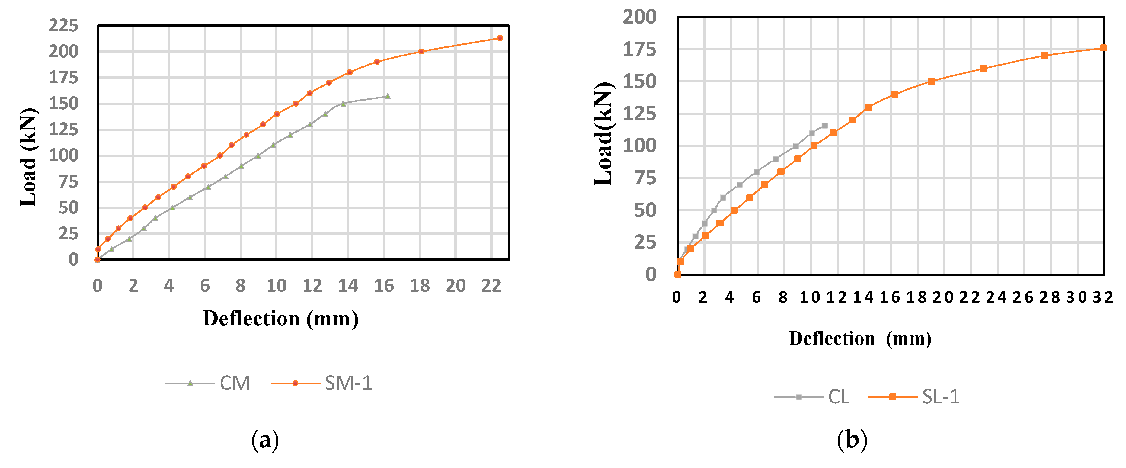
Figure 10 shows the load and deflection curves for the specimen (SM-1) and (SL-1) with the corresponding control beams. These beam specimens were strengthened using two CFRPs strips along the entire beam span. As mentioned earlier, beam (SH-1) was excluded from this study because of the shear failure observed. As shown in Figure 10a, the ultimate load for beam (SM-1) was 213 kN, while it was 157 kN for control beam CM. The enhancement ratio was 35.67% for (SM-1) compared to the control beam. Similarly, Figure 10b shows that the ultimate load for (SL-1) was 176.65 kN, while 116 kN was recorded for control beam CL. The enhancement ratio for (SL-1) was 52.28% compared to the control beam. A higher enhancement ratio in the ultimate capacity was observed in (SL-1), which indicates that applying two NSM-CFRPs strips along the entire span length had a better enhancement ratio in the low concrete-compressive-strength compared to that of medium concrete compressive strength.
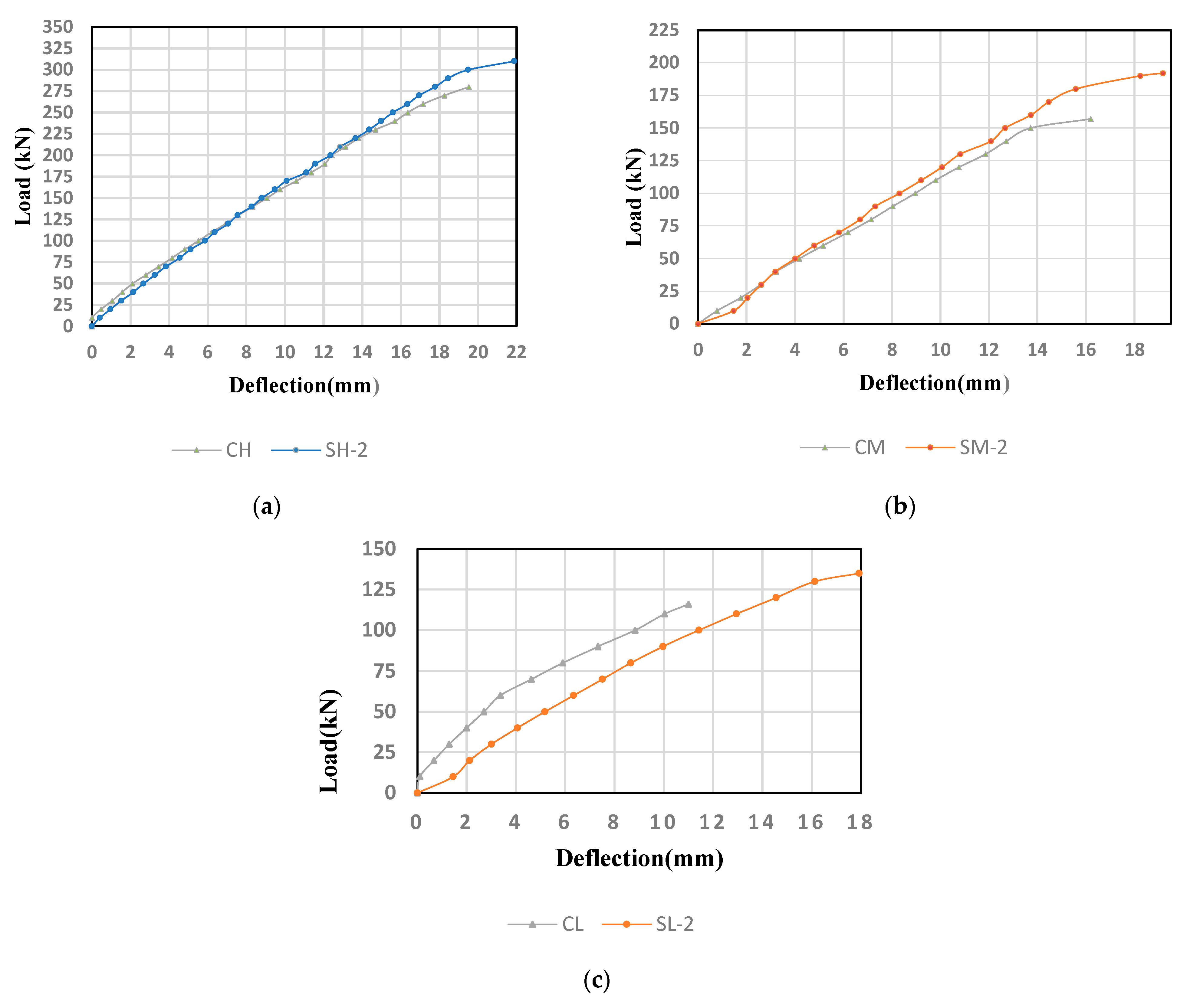
Figure 11 shows the load-deflection curve for (SH-2), (SM-2), and (SL2) and their corresponding control beams. All specimens had two strips along the middle half of the beam span at the maximum moment area. The ultimate load for beam (SH-2), as shown in Figure 11a, was 310 kN, while it was 280 kN for the control beam CH. (SH-2) showed a higher ultimate capacity than its control beam by 10.72%. Likewise, the ultimate load for beam (SM-2) was 192 kN, while it was 157 kN for control beam CM, as shown in Figure 11b. The enhancement ratio was 22.29% for (SM-2) compared to the control beam. Similarly, Figure 11c shows that the ultimate load for (SL-2) was 138 kN, while it was 116 kN for the control beam CL. (SL-2) showed a higher load-carrying capacity than its control beam by 19%.
It was observed that (SM-2) recorded the highest enhancement in ultimate load capacity relative to its control beam, followed by (SL-2) and (SH-2), respectively. The enhancement ratios were 10.72%, 22.29%, and 19% for (SH-2), (SM-2), and (SL-2) specimens, respectively, indicating that strengthening using two CFRPs strips along the middle span length had a better enhancement ratio in the medium compressive strength, followed by low strength, and then by high concrete compressive strength. Due to the cover separation that occurred in (SM-2) and (SL-2), those beams achieved less ductility behavior than (SH-2). These results matched the results of Obaidat et al. [46].
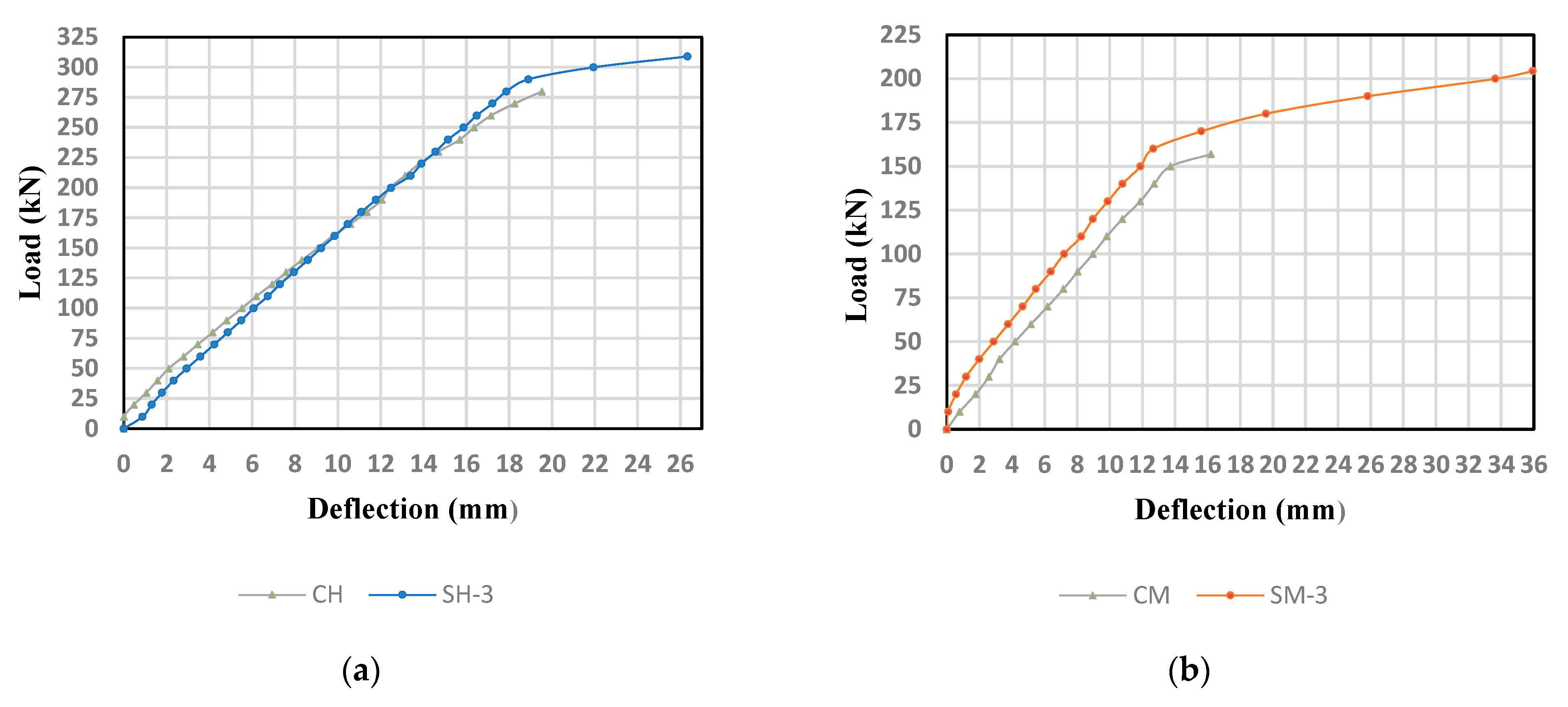
Figure 12 shows the load and deflection curve for beams specimen (SH-3) and (SM-3) and the corresponding control beams. Both beams had one CFRPs strip along the entire beam span. As illustrated in Figure 12a, the ultimate load for beam (SH-3) was 309 kN compared to 280 kN for the control beam CH. Beam (SH-3) had a higher loading capacity than its control beam by 10.36%. Similarly, Figure 12b shows that the ultimate load for beam (SM-3) was 204.31 kN, while it was 157 kN for control beam CM. The enhancement ratio was 30% for (SM-1) compared to the reference beam. Contrary to the (SH-3) beam, it was noticed that (SM-3) showed a higher ultimate load capacity. The enhancement ratios were 10.36% and 30%, respectively, for both (SH-3) and (SM-3) relative to their control beam. Thus, strengthening using one CFRPs strip along the entire span length had a better enhancement ratio in the medium compressive strength compared to the high concrete strength.

3.4. Effect of NSM-CFRP Strip Length

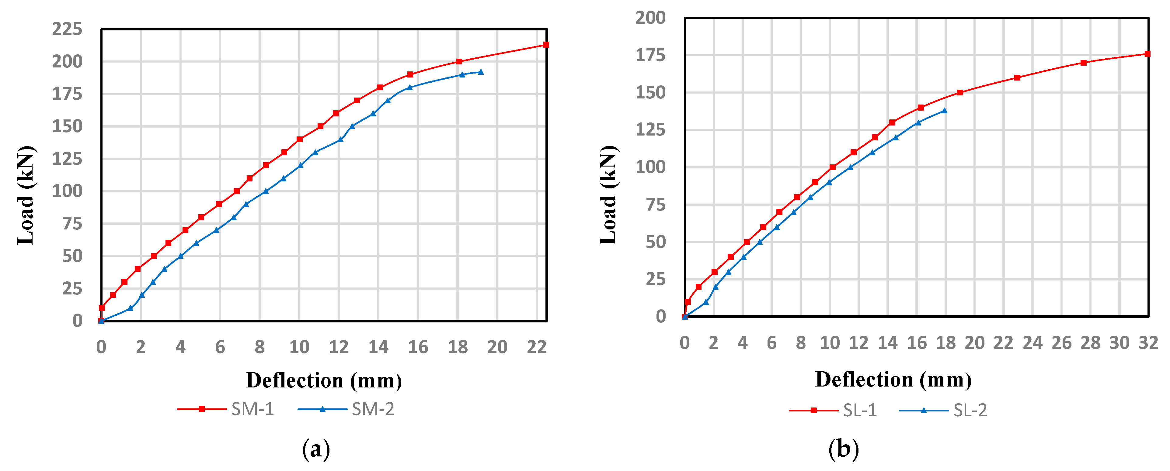
Two CFRPs strip lengths were used in the experimental program along the entire span length from support to support (SM-1 and SL-1) and along the middle half of the span at the area of maximum moment (SM-2 and SL-2). Figure 13 shows the effect of CFRPs strip length on the behavior of the strengthened beams. It can be observed that the ultimate capacity for (SM-1) was higher than (SM-2) by 10.94%. Similarly, the ultimate load capacity for (SL-1) was higher than (SL-2) by 28.01%. This clearly indicates that strengthening using two CFRPs strips along the entire span length enhanced the flexural capacity better than strengthening using two CFRPs strips along the middle half of the span. Additionally, (SM-1) and (SL-1) showed higher ductility compared to (SM-2) and (SL-2) owing to the cover separation that occurred in the latter, matching the findings of Obaidat et al. [46].

3.5. Effect of Number of CFRPs Strips

Figure 14 demonstrates the load and deflection curves for (SM-1) and (SM-3), i.e., using one or two CFRPs strips along the entire beam span length in group M. The ultimate load capacity for (SM-1) is higher than (SM-3) by 4.25%. It can be noticed that flexural strengthening using two CFRPs strips enhanced the ultimate load in a better way than strengthening using only one CFRPs strip. Thus, the number of CFRPs strips has a considerable effect on the flexural capacity. These results are matching with Obaidat et al. [45]. On the other hand, (SM-3) showed higher ductility than (SM-1).

4. Theoretical Results

4.1. Flexural Strengthening of RC Beams Using NSM-CFRPs Strips

The design calculation stages for flexural beam capacity based on ACI 440.2R-17 guidelines are as follows [44]:
Step One: 
Computing the design tensile characteristics of CFRPs
Initially, the ultimate design-tensile strength of CFRPs strips (ffu) and their ultimate-rupture strain (εfu) are computed through the following equations:
ffu = CE × ffu*
εfu = CE × εfu*
where ffu* is the ultimate tensile strength, εfu* is the ultimate rupture strain of the CFRPs presented from the manufacturer company, and CE is a reduction factor for the environmental condition and is selected from Table 9.1 from the ACI-440R-17 code [44].
Using Hooke’s law, the tensile elasticity modulus of CFRPs (Efu) is computed by the following equation:
E fu = f f u ε f u
Step Two: 
Computing the concrete properties based on the ACI 318 [46] equations
In this step, the concrete elasticity modulus (Ec) and the depth equivalent factor for rectangular-compressive-stress blocks (β1) will be computed for the three types of concrete compressive strength used in this research study using the ACI 318 [46] equations as follows:
β 1 = 1.05 0.05 f c 6.9
E c = 4700 f c
Step Three: 
Computing the existing concrete strain on the soffit (εbi)
The existing strain in concrete at CFRPs strips installation (εbi) is calculated using the following equation:
ε bi = MDL   ( d f k d I c r E c )
However, in this study εbi is neglected since the beams were unloaded prior to the strengthening and their own weight was very small [1].
Step Four: 
Identifying the bond-depending coefficient of CFRPs (Km)
According to the manufacturer recommendations (SIKA Company), the bond-dependent coefficient (Km) for the CFRPs strips used in this research was “0.7”.
Step Five: 
Assuming the depth of the neutral axis (c)
In this step, the initial value for the neutral-axis depth (c) will be assumed using the following equation:
cinitial = 0.2d
This value is modified after verifying for equilibrium.
Step Six: 
Computing the effective concrete and CFRPs strain level (εc, εfe)
After assuming the initial value of c in the previous step, the effective concrete strain (εc) and the effective CFRPs strain (εfe) will be determined using the following equations:
ε c = ( ε fd + ε bi )     ( c d f c )  
ε fe = 0.003 ( d f c c ) K m   ε f d
where df is the effective CFRPs flexural depth.
Step Seven: 
Computing the strain in the reinforcement steel (εs)
At step number seven, the strain in reinforcement steel (εs) will be computed using the following equation:
ε s = ( ε fe + ε bi )   ( d c d f c )
Step Eight: 
Computing the stress level in CFRPs strips and reinforcement steel
Based on the effective CFRPs strain level (εfe) and strain in the reinforcement steel (εs) obtained in the previous two steps, the stress level for the CFRPs strips and steel reinforcement can be computed using the following equations:
f s ,   s = E s   ×   ε s     f y
ffe = Ef × εfe
Step Nine: 
Computing the internal force and verifying equilibrium
In this step, the concrete-stress block factors (β1 and α) will be calculated using the following equations:
β 1 = 4 ε c ε c 6 ε 2 ε c  
α = 3 ε c ε c ε c 2 3 β ε c 2
ε c = 1.7 f c Ec
where εc′ is the fc corresponding strain.
Step Ten: 
Adjusting c value till reached equilibrium
All steps from six to nine will be repeated using different values of c until the force equilibrium is satisfying.
Step Eleven: 
Computing the nominal flexure strength (Mn)
The design flexural strength is estimated using the following equations:
M ns = A s × f s × ( d β 1 c 2 )
M nf = A f × f e × ( d f   β 1 c 2 )
Mn = (Mns + Mnf)
where Mns, Mnf are the nominal flexural strength for the steel reinforcement and CFRP strips, respectively.

4.2. Comparison between Experimental and Theoretical Results

The values of the theoretical ultimate capacity obtained from the ACI 318-19 code [46] for the control specimens and from the ACI 440.2R guidelines [44] for the strengthened specimens are compared with the ultimate capacity obtained from experimental results for all specimens (Table 6). It can be concluded that the theoretical calculations provide lower results than the experimental results, implying that both ACI 318 code [46] and ACI 440 guidelines [44] were conservative in estimating the ultimate flexural capacity.
It is important to point out that the length of the CFRPs strips is not considered in the ACI 440.2R guidelines [44] equations for calculating the area of CFRPs composites (Af). Based on that, the beams that were strengthened by two CFRPs strips at the entire span length and strengthened by two CFRPs strips along the middle half of the span had the same flexural capacity.

5. Conclusions

In this research, an experimental test was conducted to investigate the flexural behavior of rectangular RC beams with three different concrete compressive strengths and reinforcement ratio of about (0.5 ρmax). Eleven RC beams were intended to fail in flexure; eight of them were strengthened with NSM-CFRPs strips using different schemes while the rest were used as control beams. The main objectives of this research were to evaluate the effect of using one and two horizontal NSM-CFRPs strips at full and middle span length on the flexural capacity of RC beams for low, medium, high compressive strength. The main findings drawn from the study are the following:
  • The experimental results confirmed the effectiveness of using the internally bonded NSM-CFRP strips as a strengthening technique. The results showed an enhancement in the flexural capacity of the strengthened RC beams between 10.36% and 52.28%.
  • The CFRP strip number considerably affected the flexural load-carrying capacities for beams with medium concrete strength. Strengthening using two horizontal NSM strips showed better ultimate load values compared to that of only one horizontal strip of 35.67% and 30%, respectively.
  • The two horizontal NSM-CFRP strips embedded along the entire span length, rather than the area of the maximum moment, had a significant effect on increasing the flexural strength for the tested concrete compressive strength values such that the beams (SM-1) and (SL-1) gained, respectively, 10.94% and 28.01% ultimate load higher than beams (SM-2) and (SL-2).
  • The ACI 440.2R guide is conservative in predicting the ultimate flexural capacity since all the experimental results gave a higher ultimate load capacity than the theoretical results. The ratio between the experimental and theoretical results was less than one. Strengthening with one horizontal CFRP strip was the most conservative, followed by the two horizontal strips embedded along the entire span length and the two horizontal CFRP strips at the middle half of the span.
  • Compared to the medium compressive strength, better enhancement ratios were recorded in beams with two horizontal CFRP strips along the entire span length and cast with low concrete strength value. The enhancement ratios were 52.28% and 35.67% for the low and medium compressive strengths, respectively.
  • Relative to the reference beam, the use of two horizontal NSM strips along the middle length and one horizontal strip along the entire span length had a better enhancement ratio in the medium compressive strength of 22.29% and 30%, respectively, compared to the high compressive strength of 10.72% and 10.36%.
  • The improvement ratio in between the schemes approaches each other when the concrete compressive strength is increased. So, the difference in the schemes in high-concrete strength does not give a significant difference. The difference between the SH-2 and SH-3 enhancement ratios was about 0.37%.
  • A good confirmation was noted in the experimental and theoretical results using the ACI 440.2 guideline, where the percent reduction was in the range of 19–28%.
  • Recommendations and Future Work
More research is needed on the effect of using the NSM-CFRPs strips on the flexural behavior of the rectangular RC beams with different compressive strengths under different parameters, such as using more than one layer or staggered layers of the NSM-CFRPs strips at different lengths and orientations. Further studies are also recommended to investigate the effect of the anchorage system on the NSM-CFRPs strips.

Author Contributions

Conceptualization, M.A.-J.; methodology, H.K.; validation, H.A.-z. and H.K.; formal analysis, M.A.-J.; investigation, H.A.-z.; resources, M.A.-J.; data curation, H.A.-z.; writing—original draft preparation, H.A.-z.; writing—review and editing, H.K. and M.A.-J.; visualization, M.A.-J. and H.K.; supervision, M.A.-J.; project administration, M.A.-J. and H.K. All authors have read and agreed to the published version of the manuscript.

Funding

This research received no external funding.

Institutional Review Board Statement

Not applicable.

Informed Consent Statement

Not applicable.

Data Availability Statement

The article includes all the research data.

Acknowledgments

The authors would like to acknowledge the deanship of academic research at the University of Jordan for their financial support.

Conflicts of Interest

The authors declare no conflict of interest.

References

  1. El-Gamal, S.; Al-Nuaimi, A.; Al-Saidy, A.; Al-Lawati, A. Efficiency of near surface mounted technique using fiber reinforced polymers for the flexural strengthening of RC beams. Constr. Build. Mater. 2016, 118, 52–62. [Google Scholar] [CrossRef]
  2. Ibrahim, M.; Wakjira, T.; Ebead, U. Shear strengthening of reinforced concrete deep beams using near-surface mounted hybrid carbon/glass fibre reinforced polymer strips. Eng. Struct. 2020, 210, 110412. [Google Scholar] [CrossRef]
  3. Heiza, K.; Nabil, A.; Meleka, N.; Tayel, M. State-of-the Art Review: Strengthening of Reinforced Concrete Structures–Different Strengthening Techniques. Int. Conf. Nano-Technol. Constr. 2014, 1, 1–24. [Google Scholar]
  4. Abdel-Jaber, M. Influence of Externally Bonded CFRP on the Shear Behavior of Strengthened and Rehabilitated Reinforced Concrete T-Beams Containing Shear Stirrups. Fibers 2021, 9, 87. [Google Scholar] [CrossRef]
  5. Aykac, S.; Kalkan, I.; Aykac, B.; Karahan, S.; Kayar, S. Strengthening and Repair of Reinforced Concrete Beams Using External Steel Plates. J. Struct. Eng. 2013, 139, 929–939. [Google Scholar] [CrossRef]
  6. Yang, J.; Haghani, R.; Blanksvärd, T.; Lundgren, K. Experimental study of FRP-strengthened concrete beams with corroded reinforcement. Constr. Build. Mater. 2021, 301, 124076. [Google Scholar] [CrossRef]
  7. Abdel-Jaber, M.; Abdel-Jaber, M.; Katkhuda, H.; Shatarat, N.; El-Nimri, R. Influence of Compressive Strength of Concrete on Shear Strengthening of Reinforced Concrete Beams with Near Surface Mounted Carbon Fiber-Reinforced Polymer. Buildings 2021, 11, 563. [Google Scholar] [CrossRef]
  8. Hu, B.; Zhou, Y.; Xing, F.; Sui, L.; Luo, M. Experimental and theoretical investigation on the hybrid CFRP-ECC flexural strengthening of RC beams with corroded longitudinal reinforcement. Eng. Struct. 2019, 200, 109717. [Google Scholar] [CrossRef]
  9. Masoud, S.; Soudki, K.; Topper, T. CFRP-Strengthened and Corroded RC Beams under Monotonic and Fatigue Loads. J. Compos. Constr. 2001, 5, 228–236. [Google Scholar] [CrossRef]
  10. Shehata, I.A.E.M.; Shehata, L.D.C.D.; Santos, E.W.F.; Simões, M.L.D.F. Strengthening of reinforced concrete beams in flexure by partial jacketing. Mater. Struct. 2008, 42, 495–504. [Google Scholar] [CrossRef]
  11. Mehdi, S. Flexural Strengthening of RC Columns with Low Longitudinal Steel Ratio using GFRP Bars. Int. J. Concr. Struct. Mater. 2019, 13, 42. [Google Scholar]
  12. Xing, G.; Ozbulut, O.E.; Al-Dhabyani, M.A.; Chang, Z.; Daghash, S.M. Enhancing flexural capacity of RC columns through near surface mounted SMA and CFRP bars. J. Compos. Mater. 2020, 54, 4661–4676. [Google Scholar] [CrossRef]
  13. Husain, M.; Eisa, A.S.; Hegazy, M.M. Strengthening of reinforced concrete shear walls with openings using carbon fi-ber-reinforced polymers. Int. J. Adv. Struct. Eng. 2019, 11, 129–150. [Google Scholar] [CrossRef] [Green Version]
  14. Siddika, A.; Al Mamun, A.; Ferdous, W.; Alyousef, R. Performances, challenges and opportunities in strengthening reinforced concrete structures by using FRPs—A state-of-the-art review. Eng. Fail. Anal. 2020, 111, 104480. [Google Scholar] [CrossRef]
  15. Wang, Q.; Li, T.; Zhu, H.; Su, W.; Hu, X. Bond enhancement for NSM FRP bars in concrete using different anchorage systems. Constr. Build. Mater. 2020, 246, 118316. [Google Scholar] [CrossRef]
  16. Alexander, M.; Beushausen, H. Durability, service life prediction, and modelling for reinforced concrete structures—Review and critique. Cem. Concr. Res. 2019, 122, 17–29. [Google Scholar] [CrossRef]
  17. Viswanathan, G.; Oviya, G.; Priyadharshini, A.S.; Santhiya, K.R.; Yuvasri, M. Experimental Study on Strengthening of RC Beam using Fiber Wrapping. Int. J. Adv. Res. Innov. 2019, 6, 2347–3258. [Google Scholar]
  18. Nerilli, F.; Vairo, G. Strengthening of reinforced concrete beams with basalt-based FRP sheets: An analytical assessment. AIP Conf. Proc. 2016, 1738, 270016. [Google Scholar] [CrossRef]
  19. Abdel-Jaber, M.S.; Shatanawi, A.S.; Abdel-Jaber, M. Guidelines for Shear Strengthening of Beams Using Carbon Fiber-Reinforced Polymer (FRP) Plates. Jordan J. Civ. Eng. 2007, 1, 327–335. [Google Scholar]
  20. Kadhim, M.M.A.; Adheem, A.H.; Jawdhari, A.R. Nonlinear Finite Element Modelling and Parametric Analysis of Shear Strengthening RC T-Beams with NSM CFRP Technique. Int. J. Civ. Eng. 2019, 17, 1295–1306. [Google Scholar] [CrossRef]
  21. Abed, D.J.; Abdel-Jaber, M.S.; Shatarat, N.K. Behavior of Square Reinforced Concrete Columns Strengthened with Carbon Fiber Reinforced Polymers (CFRP) under Eccentric Loading. Int. J. Civ. Eng. 2018, 9, 532–547. [Google Scholar]
  22. Al-Ghanem, H.; Al-Asi, A.; Abdel-Jaber, M.; Alqam, M. Shear and Flexural Behavior of Reinforced Concrete Deep Beams Strengthened with CFRP Composites. Mod. Appl. Sci. 2017, 11, 110. [Google Scholar] [CrossRef] [Green Version]
  23. Ashour, A.; El-Refaie, S.; Garrity, S. Flexural strengthening of RC continuous beams using CFRP laminates. Cem. Concr. Compos. 2004, 26, 765–775. [Google Scholar] [CrossRef]
  24. Fanning, P.J.; Kelly, O. Ultimate Response of RC Beams Strengthened with CFRP Plates. J. Compos. Constr. 2001, 5, 122–127. [Google Scholar] [CrossRef]
  25. Ge, W.; Tang, R.; Wang, Y.; Zhang, Z.; Sun, C.; Yao, S.; Lu, W. Flexural performance of ECC-concrete composite beams strengthened with carbon fiber sheet. Results Eng. 2022, 13, 100334. [Google Scholar] [CrossRef]
  26. Maqsood, N.; Rimašauskas, M. Delamination observation occurred during the flexural bending in additively manufactured PLA-short carbon fiber filament reinforced with continuous carbon fiber composite. Results Eng. 2021, 11, 100246. [Google Scholar] [CrossRef]
  27. Beramly, M.; Jaber, M.A.; Katkhuda, H.; Shatarat, N.; Al-Diseet, M. Shear strengthening and rehabilitating of reinforced concrete T-beams using externally carbon fiber reinforced polymer sheets. J. Appl. Eng. Sci. 2022, 20, 498–510. [Google Scholar] [CrossRef]
  28. Al-Shamayleh, R.; Al-Saoud, H.; Abdel-Jaber, M.; Alqam, M. Shear and flexural strengthening of reinforced concrete beams with variable compressive strength values using externally bonded carbon fiber plates. Results Eng. 2022, 14, 100427. [Google Scholar] [CrossRef]
  29. Abdel-Jaber, M.S.; Walker, P.R.; Hutchinson, A.R. Shear strengthening of reinforced concrete beams using different configurations of externally bonded carbon fibre reinforced plates. Mater. Struct. 2003, 36, 291–301. [Google Scholar] [CrossRef]
  30. Hassan, S.K.H.; Abdel-Jaber, M.S.; Alqam, M. Rehabilitation of Reinforced Concrete Deep Beams Using Carbon Fiber Reinforced Polymers (CFRP). Mod. Appl. Sci. 2018, 12, 179. [Google Scholar] [CrossRef]
  31. Triantafillou, T.C. Shear Strengthening of Reinforced Concrete Beams Using Epoxy-Bonded FRP Composites. ACI Struct. J. 1998, 95, 107–115. [Google Scholar]
  32. Chen, J.; Teng, J. Shear capacity of FRP-strengthened RC beams: FRP debonding. Constr. Build. Mater. 2002, 17, 27–41. [Google Scholar] [CrossRef]
  33. Al-Saadi, N.T.K.; Mohammed, A.; Al-Mahaidi, R.; Sanjayan, J. A state-of-the-art review: Near-surface mounted FRP composites for reinforced concrete structures. Constr. Build. Mater. 2019, 209, 748–769. [Google Scholar] [CrossRef]
  34. Bilotta, A.; Ceroni, F.; Nigro, E.; Pecce, M. Efficiency of CFRP NSM strips and EBR plates for flexural strengthening of RC beams and loading pattern influence. Compos. Struct. 2015, 124, 163–175. [Google Scholar] [CrossRef]
  35. Szabó, Z.K.; Balázs, G.L. Near surface mounted FRP reinforcement for strengthening of concrete structures. Period. Polytech. Civ. Eng. 2007, 51, 33–38. [Google Scholar] [CrossRef] [Green Version]
  36. De Lorenzis, L.; Teng, J.G. Near-surface mounted FRP reinforcement: An emerging technique for strengthening structures. Compos. Part B Eng. 2007, 38, 119–143. [Google Scholar] [CrossRef]
  37. Nurbaiah, M.N.; Hanizah, A.H.; Nursafarina, A.; Ashikin, M.N. Flexural behaviour of RC beams strengthened With externally bonded (EB) FRP sheets or Near Surface Mounted (NSM) FRP rods method. In Proceedings of the 2010 International Conference on Science and Social Research (CSSR 2010), Kuala Lumpur, Malaysia, 5–7 December 2010; IEEE: Piscataway, NJ, USA, 2011; pp. 1232–1237. [Google Scholar] [CrossRef]
  38. Kuntal, V.S.; Chellapandian, M.; Prakash, S.S.; Sharma, A. Experimental Study on the Effectiveness of Inorganic Bonding Materials for Near-Surface Mounting Shear Strengthening of Prestressed Concrete Beams. Fibers 2020, 8, 40. [Google Scholar] [CrossRef]
  39. Chellapandian, M.; Prakash, S.; Sharma, A. Experimental and finite element studies on the flexural behavior of reinforced concrete elements strengthened with hybrid FRP technique. Compos. Struct. 2018, 208, 466–478. [Google Scholar] [CrossRef]
  40. Strengthening Bridge Slabs with Grouted Reinforcement. ACI J. Proc. 1949, 45, 397–406. [CrossRef]
  41. Seo, S.-Y.; Feo, L.; Hui, D. Bond strength of near surface-mounted FRP plate for retrofit of concrete structures. Compos. Struct. 2012, 95, 719–727. [Google Scholar] [CrossRef]
  42. Sharaky, I.; Torres, L.; Sallam, H. Experimental and analytical investigation into the flexural performance of RC beams with partially and fully bonded NSM FRP bars/strips. Compos. Struct. 2014, 122, 113–126. [Google Scholar] [CrossRef]
  43. Sharaky, I.; Torres, L.; Baena, M.; Miàs, C. An experimental study of different factors affecting the bond of NSM FRP bars in concrete. Compos. Struct. 2013, 99, 350–365. [Google Scholar] [CrossRef]
  44. ACI 440.2R. Guide for the Design and Construction of Externally Bonded FRP Systems for Strengthening Concrete Structures; American Concrete Institute: Farmington Hills, MI, USA, 2017; p. 116. [Google Scholar]
  45. Obaidat, Y.T.; Barham, W.S.; Aljarah, A.H. New anchorage technique for NSM-CFRP flexural strengthened RC beam using steel clamped end plate. Constr. Build. Mater. 2020, 263, 120246. [Google Scholar] [CrossRef]
  46. ACI Committee 318. Building Code Requirement for Structural Concrete (ACI 318M-19); American Concrete Institute: Farmington Hills, MI, USA, 2019. [Google Scholar]
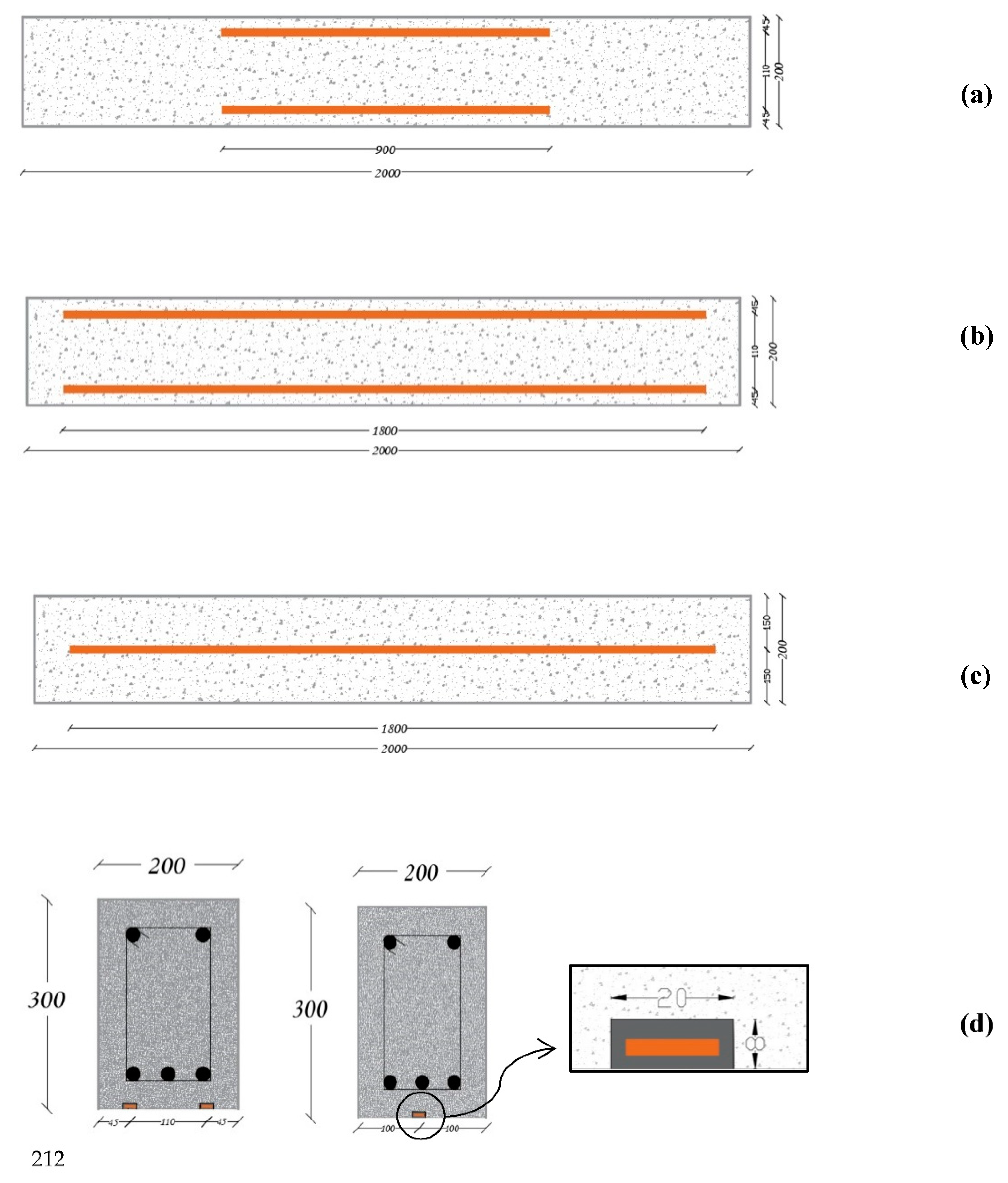
Figure 1. The longitudinal detailing of the strengthened beams at their bottom face (all dimensions are in mm(. (a) Two NSM-CFRP-strips (SH-1, SM-1, SL-1) at full span length. (b) Two NSM-CFRP-strips (SH-2, SM-2, SL-2) over the middle half of the span. (c) One NSM-CFRP-strip (SH-3, SM-3) at full span length. (d) Cross-sectional details of the strengthened specimens.
Fibers 10 00086 g001
Figure 2. Reinforcement detailing of the three groups tested (all dimensions are in mm). (a) High Concrete Strength (Group H). (b) Medium Concrete Strength (Group M). (c) Low Concrete Strength (Group L).
Fibers 10 00086 g002
Figure 3. Beam Casting and Curing.
Fibers 10 00086 g003
Figure 4. Installation of NSM-CFRP strips.
Fibers 10 00086 g004
Figure 5. Test setup and LVDTs device.
Fibers 10 00086 g005
Figure 6. Load–deflection curve for beams of group H.
Fibers 10 00086 g006
Figure 7. Load–deflection curves for beams of group M.
Fibers 10 00086 g007
Figure 8. Load–deflection curve for beams of group L.
Fibers 10 00086 g008
Figure 9. Failure modes of all specimens.
Fibers 10 00086 g009aFibers 10 00086 g009b
Figure 10. Load–deflection curve for: (a) CM and SM-1, (b) CL and SL-1.
Fibers 10 00086 g010
Figure 11. Load–deflection curve for: (a) CH and SH-2, (b) CM and SM-2, (c) CL and SL-2.
Fibers 10 00086 g011
Figure 12. Load–deflection curve for: (a) CH and SH-3, (b) CM and SM-3.
Fibers 10 00086 g012
Figure 13. Load–deflection curve for: (a) SM-1 and SM-2, (b) SL-1 and SL-2.
Fibers 10 00086 g013
Figure 14. Load–deflection curve for SM-1 and SM-3.
Fibers 10 00086 g014
Table 1. Concrete mix design.
ComponentsConcrete Class
H *M *L *
Cement/OPC (kg)345 260205
Coarse aggregate (kg)380 365365
Medium aggregate (kg)630 590590
Silica sand (kg)635700750
Crushed sand (kg)275300305
Total water (kg)172180180
605 Superplasticizer (Type G) (kg)9.67.285.7
W/C eff 0.450.630.79
* High Concrete Strength (H), Medium Concrete Strength (M), Low Concrete Strength (L).
Table 2. The mechanical and physical properties of the NSM-CFRP strip by Sika Company.
Tensile Strength (MPa)Elasticity Modulus (GPa)Density of Carbon Fiber (g/cm3)Width (mm)Thickness (mm)Strain at Break
31001651.6152.5>1.70%
Table 3. Epoxy adhesive properties by Sika Company.
DensityTensile StrengthBond StrengthElongation at BreakE-Modulus
1.30 kg/lt ± 0.1 kg/lt (parts A+B mixed)30 MPa *Concrete fracture > 4 MPa on sandblast substrate0.9% *Flexural: 3800 MPa *
Tensile: 4500 MPa *
* (7 days at +23 °C).
Table 4. Test specimen details.
Test GroupsBeam Designations Strengthening Schemes
Group H CHN/A
SH-1Two horizontal NSM-CFRP strips at full span length
SH-2Two horizontal NSM-CFRP strips over the middle half of the span
SH-3One horizontal NSM-CFRP strip at full span length
Group MCMN/A
SM-1Two horizontal NSM-CFRP strips at full span length
SM-2Two horizontal NSM-CFRP strips over the middle half of the span
SM-3One horizontal NSM-CFRP strip at full span length
Group LCLN/A
SL-1Two horizontal NSM-CFRP strips at full span length
SL-2Two horizontal NSM-CFRP strips over the middle half of the span
Table 5. Test results of all tested beams.
SpecimenUltimate Load, Pu (kN)Deflection, Δ (mm)Enhancement Ratio %Strength Factor,
SF
CH28019.53------
SH-1 *30024.447%1.07
SH-231021.2110.72%1.11
SH-330926.3310.36%1.1
CM15716.2------
SM-121322.4935.67%1.36
SM-219219.1822.29%1.22
SM-3204.3135.9430%1.3
CL1166.7------
SL-1176.6531.9552.28%1.52
SL-213817.9319%1.19
* Neglect SH-1 from results due to shear confinement losses in the transverse steel resulting from implementation errors.
Table 6. Experimental and theoretical results.
SpecimenUltimate Moment, (Mu)Ultimate Load, (Pu)Error (%)
Mu, Exp.
(kN·m)
Mu, Theo.
(KN·m)
Pu, Exp.
(kN)
Pu, Theo.
(kN)
CH12676.99280171.163.65
SH-2139.5102.66310228.1235.89
SH-3139.0592309204.4451.14
CM70.6560.1157133.5517.56
SM-195.8584.08213186.8414.00
SM-286.484.08192186.842.76
SM-391.9474.62204.31165.8223.21
CL52.235.3311678.5147.75
SL-179.4948.93176.65108.7362.47
SL-262.148.93138108.7326.92
Publisher’s Note: MDPI stays neutral with regard to jurisdictional claims in published maps and institutional affiliations.