Investigation on Corrosion Resistance and Formation Mechanism of a P–F–Zr Contained Micro-Arc Oxidation Coating on AZ31B Magnesium Alloy Using an Orthogonal Method

 and
and
Abstract
:1. Introduction
2. Experiment
2.1. Materials and Coating Preparation
2.2. Microstructural Characterization
2.3. Electrochemical Test
3. Results
3.1. Characteristics of MAO Coatings
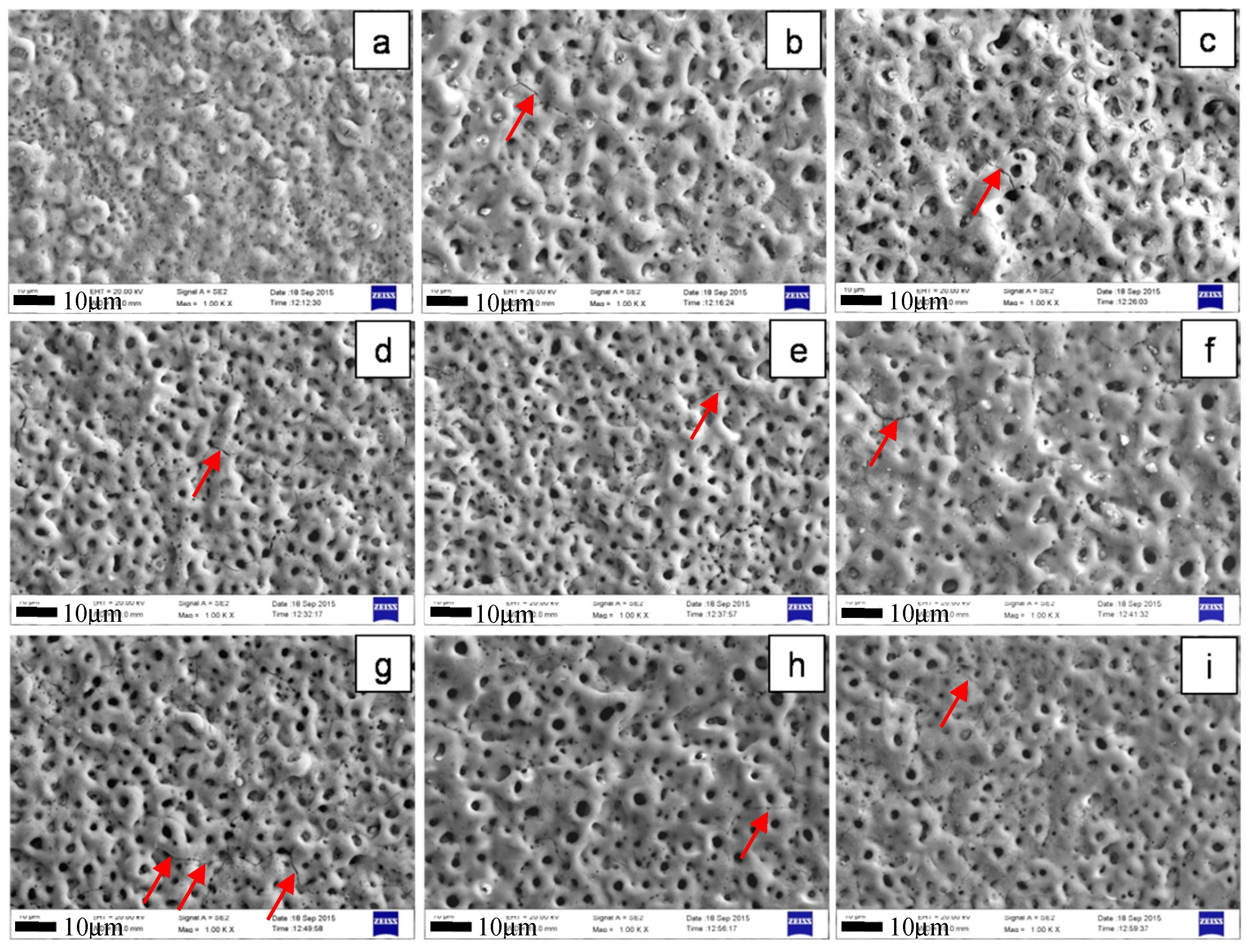
3.1.1. Surface Morphology and Chemical Composition
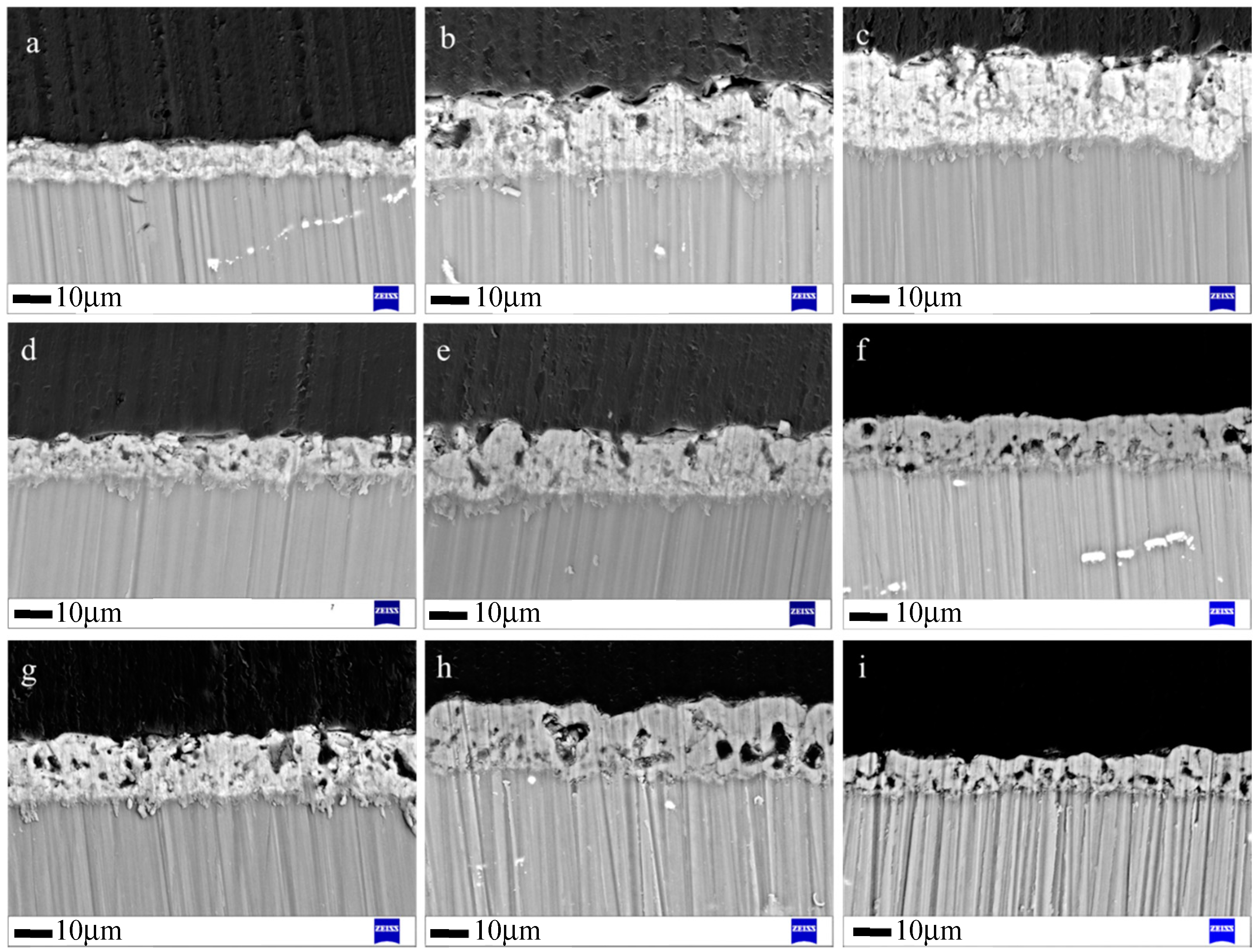
3.1.2. Cross-Sectional Morphology
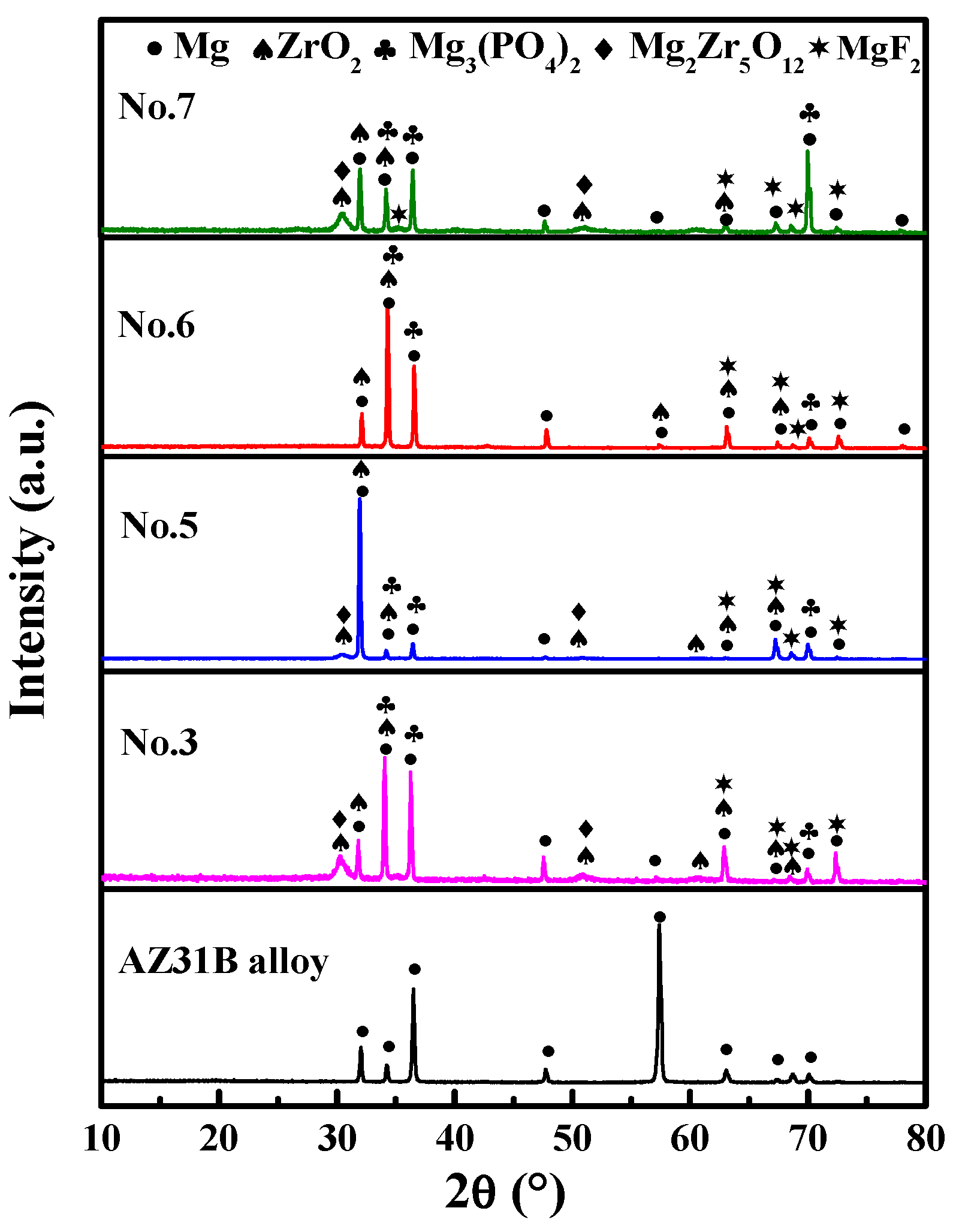
3.1.3. XRD Analysis
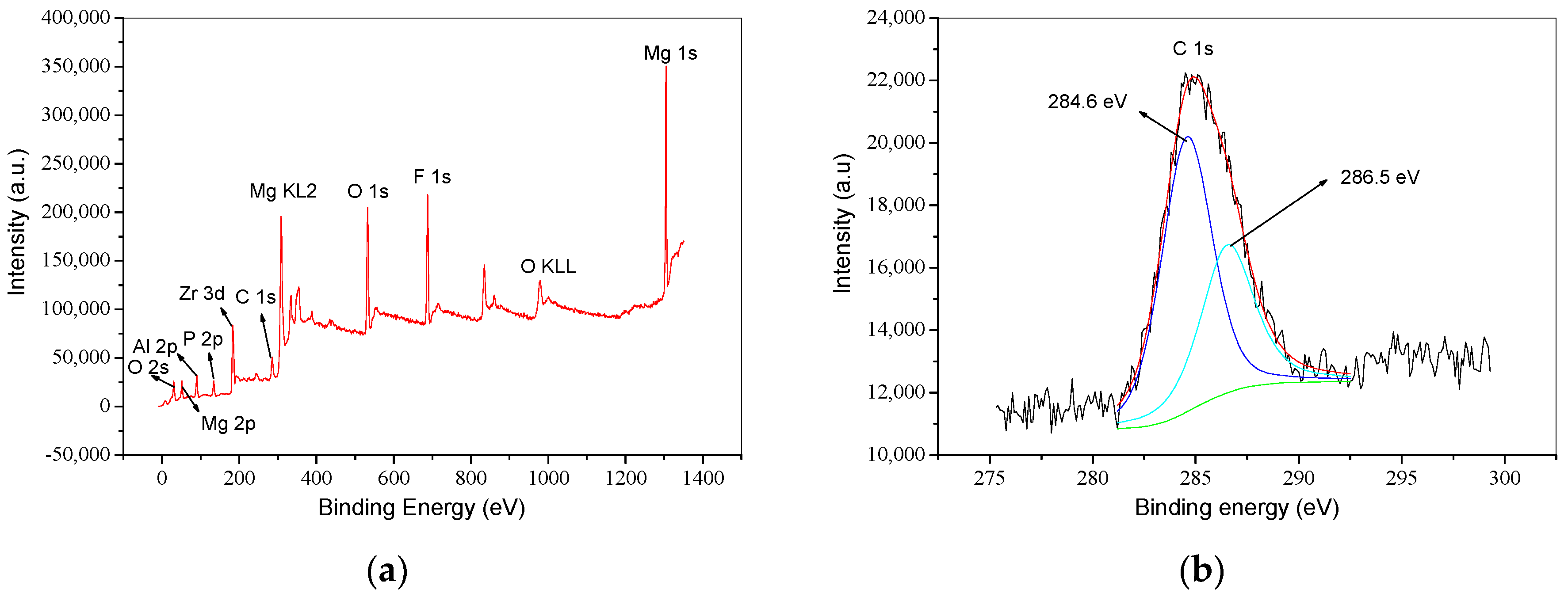
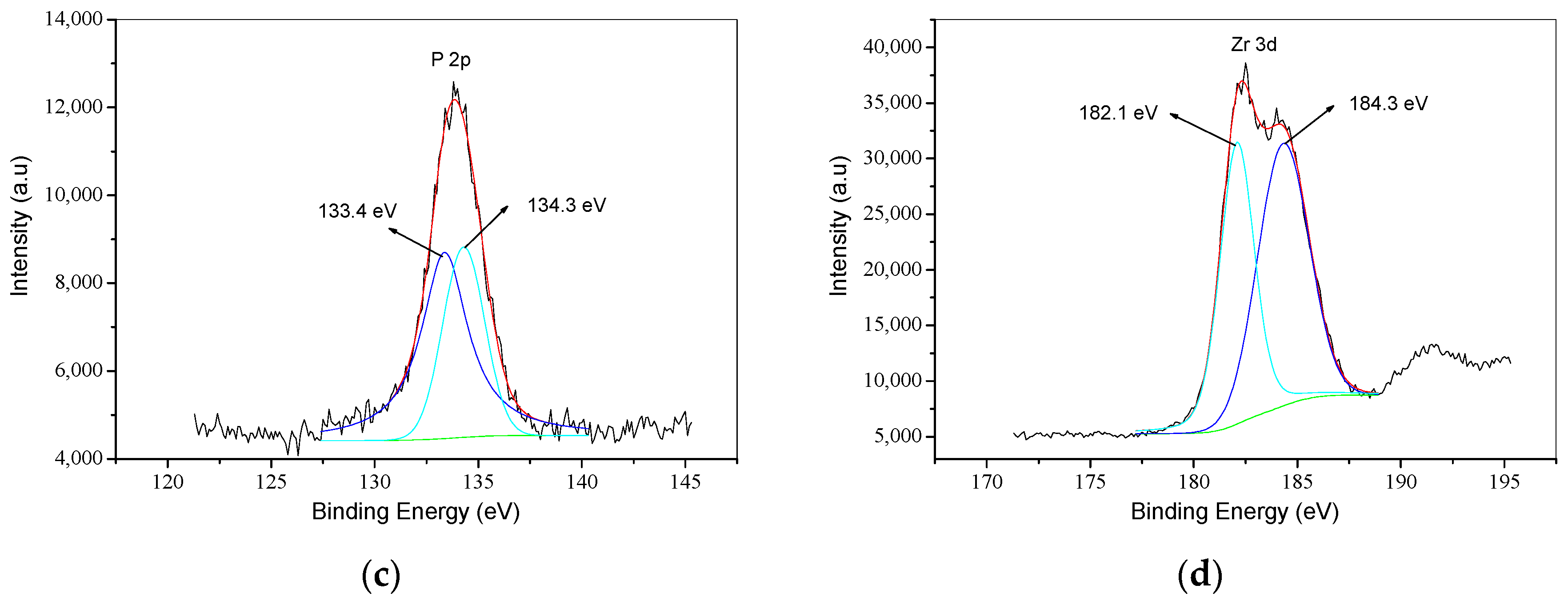
3.1.4. XPS Analysis
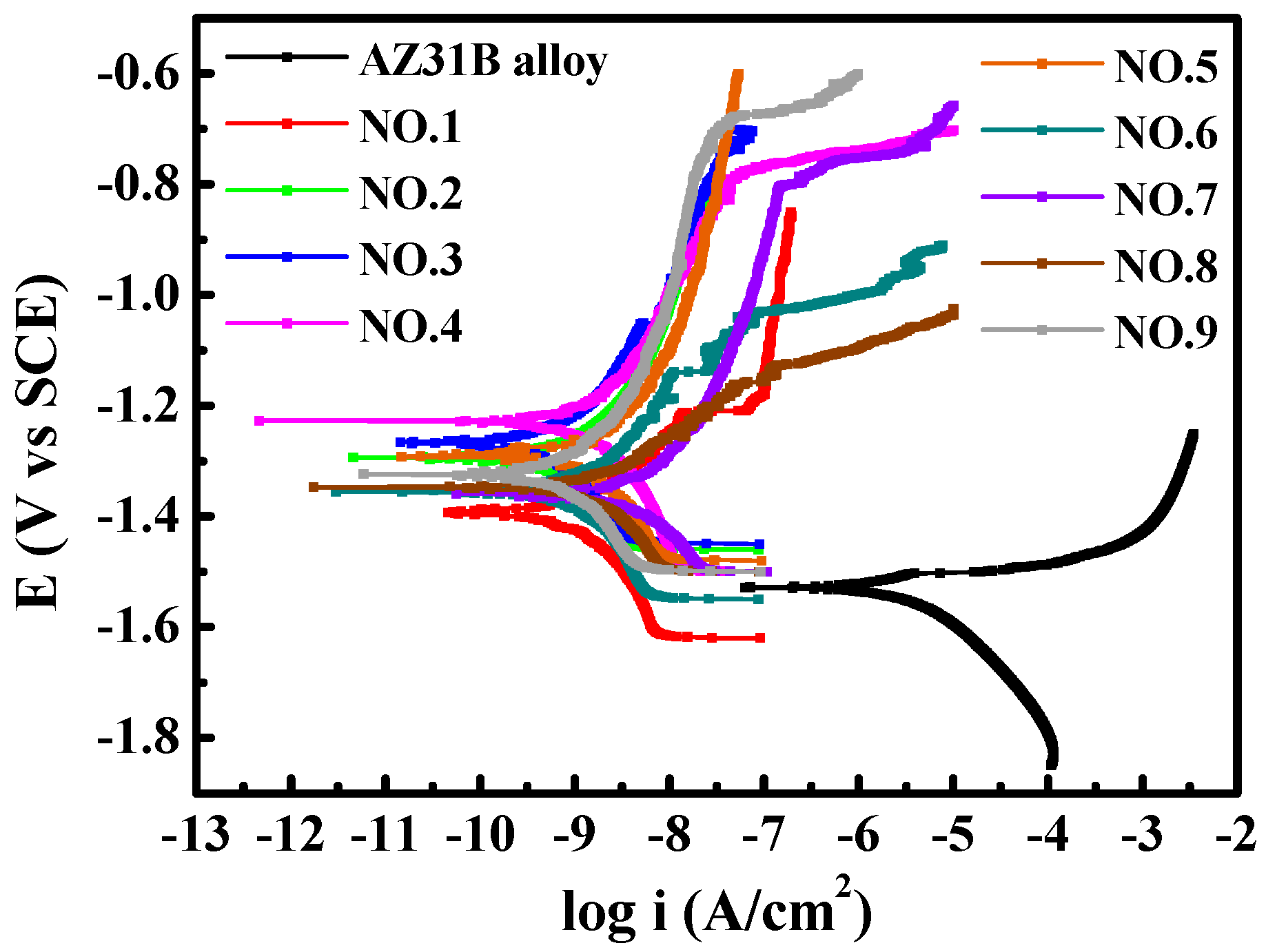
3.1.5. Corrosion Resistance
3.2. The Orthogonal Results
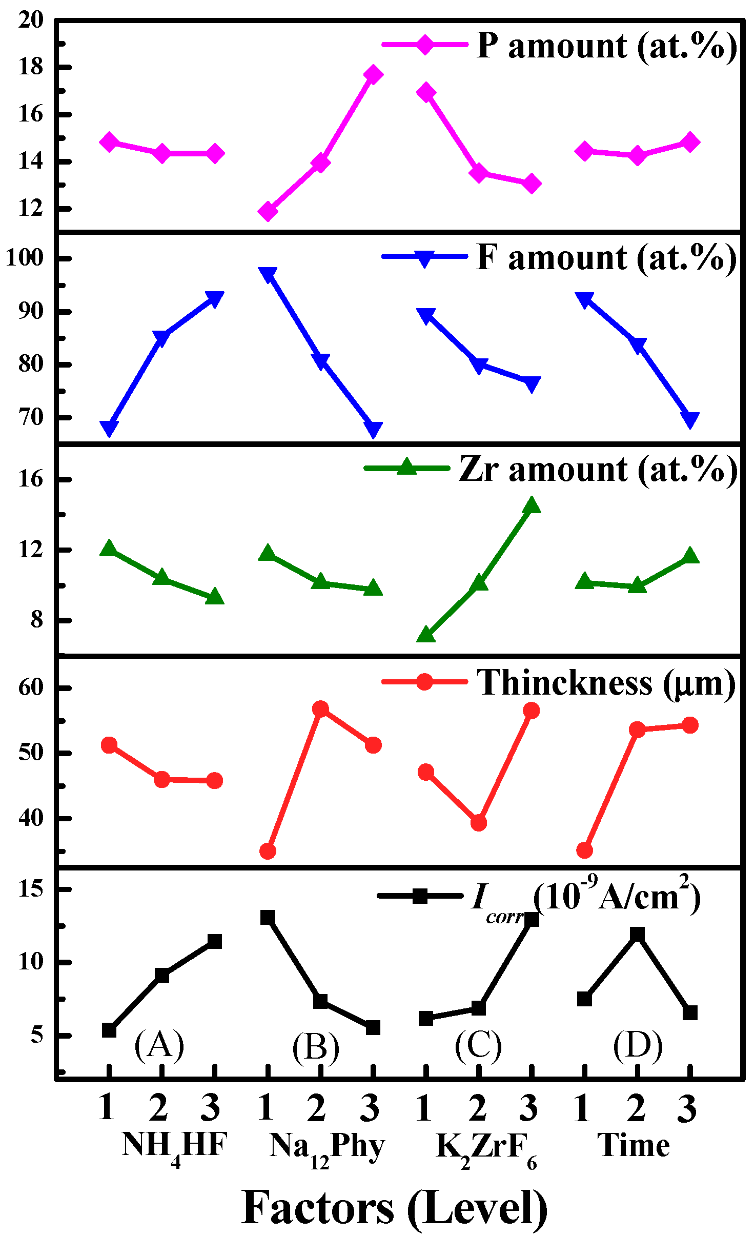
3.2.1. Influences of Processing Factors on P, F and Zr Contents
3.2.2. Influences of Processing Factors on Corrosion Resistance and Thickness
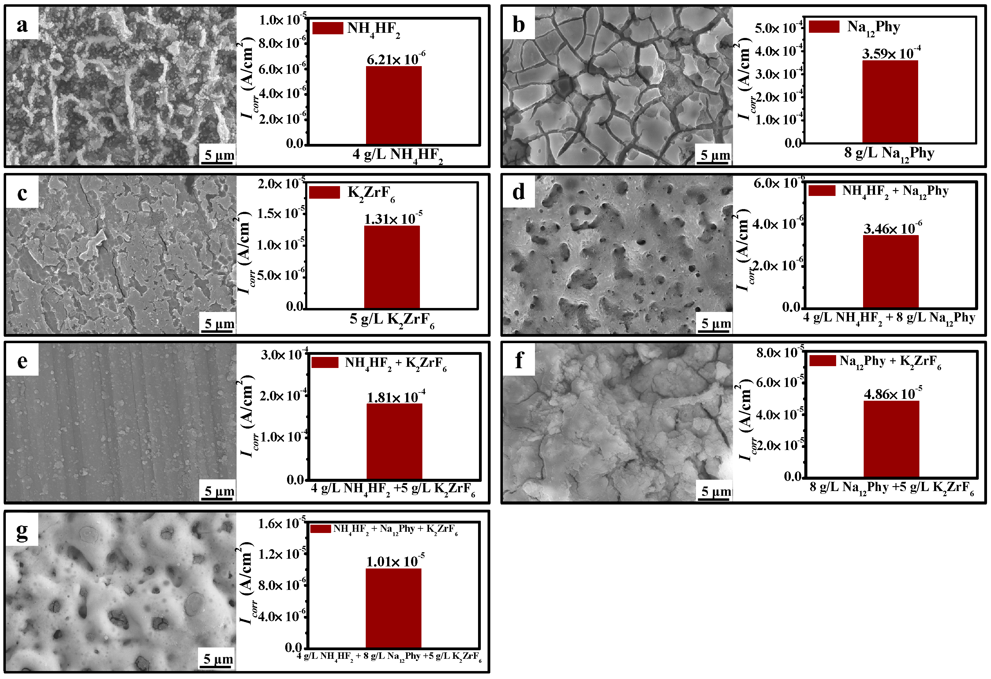
3.3. Influences of Electrolyte Components on Coating Development
4. Discussion
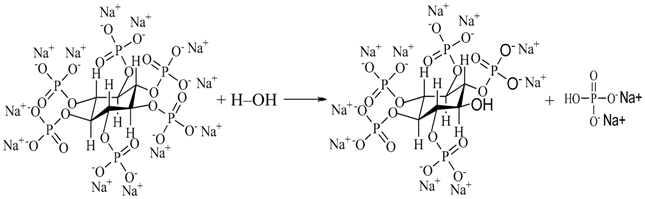
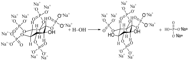
4.1. The Entrance Mechanisms of P, F, and Zr into MAO Coatings
4.2. Influence of Processing Factors on Corrosion Resistance
5. Conclusions
- NH4HF2, Na12Phy, and K2ZrF6 all partake in the coating formation, and the fabricated MAO coatings are mainly composed of Mg3(PO4)2, ZrO2, Mg2Zr5O12, and MgF2. NH4HF2 and Na12Phy, the corrosion inhibitors of magnesium alloys, are beneficial but K2ZrF6 is harmful to develop anodic coatings. Only under the combined action of NH4HF2 and Na12Phy can K2ZrF6 take part in coating formation and develop self-sealing coatings;
- The corrosion resistance of MAO coatings is synergistically determined by coating characteristics such as coating thickness, surface morphology, and phase structure, though the coating thickness plays a main role. Na12Phy significantly improves but NH4HF2 decreases the corrosion resistance of MAO coatings, while excess high K2ZrF6 is harmful to the coating corrosion resistance. Treatment time can increase the coating thickness but is the least important factor on corrosion resistance;
- P, F, and Zr compete with each other to enter into anodic coatings. The influencing rank on P content is Na12Phy concentration > K2ZrF6 concentration > treatment time > NH4HF2 concentration. With the increase of Na12Phy or the decrease of K2ZrF6 concentration, the P amount of anodic coatings increases. The sequence of processing factors on F content is Na12Phy concentration > NH4HF2 concentration > treatment time > K2ZrF6 concentration. The F amount decreases with the increasing Na12Phy concentration, decreasing NH4HF2 concentration, prolonging treatment time, or increasing K2ZrF6 concentration. The order on the Zr amount is K2ZrF6 concentration > NH4HF2 concentration > Na12Phy concentration > treatment time. The Zr content can be increased by increasing K2ZrF6 concentration, decreasing NH4HF2 and Na12Phy concentrations, or with proper treatment.
Author Contributions
Funding
Acknowledgments
Conflicts of Interest
References
- El-Sayed, M.; El-Hadidi, M.; El-Adl, W. Free non-vascularised fibular graft for treatment of post-traumatic bone defects. Acta Orthop. Belg. 2007, 73, 70–76. [Google Scholar]
- Narayanan, T.S.; Park, I.S.; Lee, M.H. Strategies to improve the corrosion resistance of microarc oxidation (MAO) coated magnesium alloys for degradable implants: Prospects and challenges. Prog. Mater. Sci. 2014, 60, 1–71. [Google Scholar] [CrossRef]
- Han, J.J.; Wan, P.; Sun, Y.; Liu, Z.Y.; Fan, X.M.; Tan, L.L.; Yang, K. Fabrication and evaluation of a bioactive Sr–Ca–P contained micro-arc oxidation coating on magnesium strontium alloy for bone repair application. J. Mater. Sci. Technol. 2016, 32, 233–244. [Google Scholar] [CrossRef]
- Krishna, L.R.; Sundararajan, G. Aqueous corrosion behavior of micro-arc oxidation (MAO)-coated magnesium alloys: A critical review. JOM 2014, 66, 1045–1060. [Google Scholar] [CrossRef]
- Cerchier, P.; Pezzato, L.; Brunelli, K.; Dolcet, P.; Bartolozzi, A.; Bertani, R.; Dabalà, M. Antibacterial effect of PEO coating with silver on AA7075. Mater. Sci. Eng. C 2017, 75, 554–564. [Google Scholar] [CrossRef]
- Mohedano, M.; Guzman, R.; Arrabal, R.; López Lacomba, J.L.; Matykina, E. Bioactive plasma electrolytic oxidation coatings-the role of the composition, microstructure, and electrochemical stability. J. Biomed. Mater. Res. B Appl. Biomater. 2013, 101, 1524–1537. [Google Scholar] [CrossRef]
- Xu, J.L.; Xiao, Q.F.; Mei, D.D.; Tong, Y.X.; Zheng, Y.F.; Li, L.; Zhong, Z.C. Microstructure, corrosion resistance and formation mechanism of alumina micro-arc oxidation coatings on sintered NdFeB permanent magnets. Surf. Coat. Technol. 2017, 309, 621–627. [Google Scholar] [CrossRef]
- Wang, Y.M.; Wang, F.H.; Xu, M.J.; Zhao, B.; Guo, L.X.; Ouyang, J.H. Microstructure and corrosion behavior of coated AZ91 alloy by microarc oxidation for biomedical application. Appl. Surf. Sci. 2009, 255, 9124–9131. [Google Scholar] [CrossRef]
- Cui, L.Y.; Zeng, R.C.; Guan, S.K.; Qi, W.C.; Zhang, F.; Li, S.Q.; Han, E.H. Degradation mechanism of micro-arc oxidation coatings on biodegradable Mg–Ca alloys: The influence of porosity. J. Alloy. Compd. 2017, 695, 2464–2476. [Google Scholar] [CrossRef]
- Verdier, S.; Boinet, M.; Maximovitch, S.; Dalard, F. Formation, structure and composition of anodic films on AM60 magnesium alloy obtained by DC plasma anodizing. Corros. Sci. 2005, 47, 1429–1444. [Google Scholar] [CrossRef]
- Chu, C.L.; Han, X.; Bai, J.; Xue, F.; Chu, P.K. Fabrication and degradation behavior of micro-arc oxidized biomedical magnesium alloy wires. Surf. Coat. Technol. 2012, 213, 307–312. [Google Scholar] [CrossRef]
- Guo, S.B.; Zhang, Y.Q.; Zhang, R.F.; Zhang, S.F.; Zhang, H.H. Influence of processing factors on properties of anodic coatings obtained on Mg–1.0Ca alloy. Mater. Chem. Phys. 2013, 141, 121–127. [Google Scholar] [CrossRef]
- Jia, Z.J.; Li, M.; Liu, Q.; Xu, X.C.; Cheng, Y.; Zheng, Y.F.; Xi, T.F.; Wei, S.C. Micro-arc oxidization of a novel Mg-1Ca alloy in three alkaline KF electrolytes: Corrosion resistance and cytotoxicity. Appl. Surf. Sci. 2014, 292, 1030–1039. [Google Scholar] [CrossRef]
- Lin, X.; Yang, X.M.; Tan, L.L.; Li, M.; Wang, X.; Zhang, Y.; Yang, K.; Hua, Z.Q.; Qiu, J.H. In vitro degradation and biocompatibility of a strontium-containing micro-arc oxidation coating on the biodegradable ZK60 magnesium alloy. Appl. Surf. Sci. 2014, 288, 718–726. [Google Scholar] [CrossRef]
- Fischerauer, S.F.; Kraus, T.; Wu, X.; Tangl, S.; Sorantin, E.; Hänzi, A.C.; Löffler, J.F.; Uggowitzer, P.J.; Weinberg, A.M. In vivo degradation performance of micro-arc-oxidized magnesium implants: A micro-CT study in rats. Acta Biomater. 2013, 9, 5411–5420. [Google Scholar] [CrossRef] [PubMed]
- Liang, J.; Srinivasan, P.B.; Blawert, C.; Dietzel, W. Comparison of electrochemical corrosion behaviour of MgO and ZrO2 coatings on AM60 magnesium alloy formed by plasma electrolytic oxidation. Corros. Sci. 2009, 51, 2483–2492. [Google Scholar] [CrossRef]
- Liu, F.; Shan, D.Y.; Song, Y.W.; Han, E.H. Effect of additives on the properties of plasma electrolytic oxidation coatings formed on AM50 magnesium alloy in electrolytes containing K2ZrF6. Surf. Coat. Technol. 2011, 206, 455–463. [Google Scholar] [CrossRef]
- Einkhah, F.; Lee, K.M.; Sani, M.A.F.; Yoo, B.; Shin, D.H. Structure and corrosion behavior of oxide layer with Zr compounds on AZ31 Mg alloy processed by two-step plasma electrolytic oxidation. Surf. Coat. Technol. 2014, 238, 75–79. [Google Scholar] [CrossRef]
- Cui, X.J.; Liu, C.H.; Yang, R.S.; Li, M.T.; Lin, X.Z. Self-sealing micro-arc oxidation coating on AZ91D Mg alloy and its formation mechanism. Surf. Coat. Technol. 2015, 269, 228–237. [Google Scholar] [CrossRef]
- Luo, H.H.; Cai, Q.Z.; Wei, B.K.; Yu, B.; He, J.; Li, D.J. Study on the microstructure and corrosion resistance of ZrO2-containing ceramic coatings formed on magnesium alloy by plasma electrolytic oxidation. J. Alloy. Compd. 2009, 474, 551–556. [Google Scholar] [CrossRef]
- Wang, S.M.; Fu, L.X.; Nai, Z.G.; Liang, J.; Cao, B.C. Comparison of corrosion resistance and cytocompatibility of MgO and ZrO2 coatings on AZ31 magnesium alloy formed via plasma electrolytic oxidation. Coatings 2018, 8, 441. [Google Scholar] [CrossRef]
- Al-Radha, A.S.D.; Dymock, D.; Younes, C.; O’Sullivan, D. Surface properties of titanium and zirconia dental implant materials and their effect on bacterial adhesion. J. Dent. 2012, 40, 146–153. [Google Scholar] [CrossRef] [PubMed]
- Liu, X.Y.; Huang, A.P.; Ding, C.X.; Chu, P.K. Bioactivity and cytocompatibility of zirconia (ZrO2) films fabricated by cathodic arc deposition. Biomaterials 2006, 27, 3904–3911. [Google Scholar] [CrossRef] [PubMed]
- Qin, H.; Zhao, Y.C.; An, Z.Q.; Cheng, M.Q.; Wang, Q.; Cheng, T.; Wang, Q.J.; Wang, J.X.; Jiang, Y.; Zhang, X.L.; et al. Enhanced antibacterial properties, biocompatibility, and corrosion resistance of degradable Mg–Nd–Zr alloy. Biomaterials 2015, 53, 211–220. [Google Scholar] [CrossRef] [PubMed]
- Zhao, Y.; Jamesh, M.I.; Li, W.K.; Wu, G.S.; Wang, C.X.; Zheng, Y.F.; Yeung, K.W.K.; Chu, P.K. Enhanced antimicrobial properties, cytocompatibility, and corrosion resistance of plasma-modified biodegradable magnesium alloys. Acta Biomater. 2014, 10, 544–556. [Google Scholar] [CrossRef]
- Kazanski, B.; Kossenko, A.; Zinigrad, M.; Lugovskoy, A. Fluoride ions as modifiers of the oxide layer produced by plasma electrolytic oxidation on AZ91D magnesium alloy. Appl. Surf. Sci. 2013, 287, 461–466. [Google Scholar] [CrossRef]
- Chen, H.; Lv, G.H.; Zhang, G.L.; Pang, H.; Wang, X.Q.; Lee, H.J.; Yang, S.Z. Corrosion performance of plasma electrolytic oxidation oxidized AZ31 magnesium alloy in silicate solutions with different additives. Surf. Coat. Technol. 2010, 205, S32–S35. [Google Scholar] [CrossRef]
- Yang, L.; Perez-Amodio, S.; Barrère-de Groot, F.Y.; Everts, V.; van Blitterswijk, C.A.; Habibovic, P. The effects of inorganic additives to calcium phosphate on in vitro behavior of osteoblasts and osteoclasts. Biomaterials 2010, 31, 2976–2989. [Google Scholar] [CrossRef]
- Liu, H.Y.; Wang, X.J.; Wang, L.P.; Lei, F.Y.; Wang, X.F.; Ai, H.L. Effect of fluoride-ion implantation on the biocompatibility of titanium for dental applications. Appl. Surf. Sci. 2008, 254, 6305–6312. [Google Scholar] [CrossRef]
- Habibovic, P.; Barralet, J.E. Bioinorganics and biomaterials: Bone repair. Acta Biomater. 2011, 7, 3013–3026. [Google Scholar] [CrossRef]
- Zaze, A.C.S.F.; Dias, A.P.; Amaral, J.G.; Miyasaki, M.L.; Sassaki, K.T.; Delbem, A.C.B. In situ evaluation of low-fluoride toothpastes associated to calcium glycerophosphate on enamel remineralization. J. Dent. 2014, 42, 1621–1625. [Google Scholar] [CrossRef] [PubMed]
- Pan, Y.K.; Chen, C.Z.; Wang, D.G.; Zhao, T.G. Effects of phosphates on microstructure and bioactivity of micro-arc oxidized calcium phosphate coatings on Mg–Zn–Zr magnesium alloy. Colloids Surf. B. 2013, 109, 1–9. [Google Scholar] [CrossRef] [PubMed]
- Hu, R.; Su, Y.Y.; Liu, H.D.; Cheng, J.; Yang, X.; Shao, Z.C. The effect of adding corrosion inhibitors into an electrolyte nickel plating bath for magnesium alloys. J. Mater. Eng. Perform. 2016, 25, 4530–4536. [Google Scholar] [CrossRef]
- Hu, R.; Su, Y.Y.; Liu, H.D. Deposition behaviour of nickel phosphorus coating on magnesium alloy in a weak corrosive electroless nickel plating bath. J. Alloy. Compd. 2016, 658, 555–560. [Google Scholar] [CrossRef]
- Dou, J.H.; Wang, C.Y.; Gu, G.C.; Chen, C. Formation of silicon-calcium-phosphate-containing coating on Mg–Zn–Ca alloy by two-step micro-arc oxidation technique. Mater. Lett. 2018, 212, 37–40. [Google Scholar] [CrossRef]
- Ma, Y.; Nie, X.; Northwood, D.O.; Hu, H. Systematic study of the electrolytic plasma oxidation process on a Mg alloy for corrosion protection. Thin Solid Films 2006, 494, 296–301. [Google Scholar] [CrossRef]
- Zhu, X.L.; Chen, J.; Scheideler, L.; Reichl, R.; Geis-Gerstorfer, J. Effects of topography and composition of titanium surface oxides on osteoblast responses. Biomaterials 2004, 25, 4087–4103. [Google Scholar] [CrossRef]
- Guo, S.F.; Zhang, H.J.; Liu, Z.; Chen, W.; Xie, S.F. Corrosion resistance of amorphous and crystalline Zr-based alloys in simulated seawater. Electrochem. Commun. 2012, 24, 39–42. [Google Scholar] [CrossRef]
- Lee, K.M.; Shin, K.R.; Namgung, S.; Yoo, B.; Shin, D.H. Electrochemical response of ZrO2-incorproated oxide layer on AZ91 Mg alloy processed by plasma electrolytic oxidation. Surf. Coat. Technol. 2011, 205, 3779–3784. [Google Scholar] [CrossRef]
- Zhang, R.Y.; Cai, S.; Xu, G.H.; Zhao, H.; Li, Y.; Wang, X.X.; Huang, K.; Ren, M.G.; Wu, X.D. Crack self-healing of phytic acid conversion coating on AZ31 magnesium alloy by heat treatment and the corrosion resistance. Appl. Surf. Sci. 2014, 313, 896–904. [Google Scholar] [CrossRef]
- Zeng, Y.F.; Ko, T.P.; Lai, H.L.; Cheng, Y.S.; Wu, T.H.; Ma, W.H.; Chen, C.C.; Yang, C.S.; Cheng, K.J.; Huang, C.H.; et al. Crystal structures of bacillus alkaline phytase in complex with divalent metal ions and inositol hexasulfate. J. Mol. Biol. 2011, 409, 214–224. [Google Scholar] [CrossRef] [PubMed]
- Sun, T.; Ning, W.M.; Yu, Y.Q.; Zhang, G.R. Appendix 3: Solubility product constants at 298.15 K. In University Chemistry (І); Ning, W.M., Ed.; Northeast University Press: Shenyang, China, 1993; p. 402. (In Chinese) [Google Scholar]
- Rehaman, Z.U.; Shin, S.H.; Hussain, I.; Koo, B.H. Investigation of hybrid PEO coatings on AZ31B magnesium alloy in alkaline K2ZrF6–Na2SiO3 electrolyte solution. Prot. Met. Phys. Chem. 2017, 53, 495–502. [Google Scholar] [CrossRef]
- An, L.Y.; Ma, Y.; Liu, Y.P.; Sun, L.; Wang, S.; Wang, Z.Y. Effects of additives, voltage and their interactions on PEO coatings formed on magnesium alloys. Surf. Coat. Technol. 2018, 354, 226–235. [Google Scholar] [CrossRef]
- Apelfeld, A.; Krit, B.; Ludin, V.; Morozova, N.; Vladimirov, B.; Wu, R.Z. The characteristics of plasma electrolytic oxidation coatings on AZ41 magnesium alloy. Surf. Coat. Technol. 2017, 322, 127–133. [Google Scholar] [CrossRef]
- Mohedano, M.; Arrabal, R.; Mingo, B.; Pardo, A.; Matykina, E. Role of particle type and concentration on characteristics of PEO coatings on AM50 magnesium alloy. Surf. Coat. Technol. 2018, 334, 328–335. [Google Scholar] [CrossRef]
- Notoya, T.; Otieno-Alego, V.; Schweinsberg, D.P. The corrosion and polarization behaviour of copper in domestic water in the presence of Ca, Mg, and Na-salts of phytic acid. Corros. Sci. 1995, 37, 55–65. [Google Scholar] [CrossRef]
- Guo, X.L.; Feng, Z.C. Belinda Hurley, Rudolph Buchheit, Entrapped molybdate in phytate film and the corresponding anodic corrosion inhibition on AA2024-T3. J. Electrochem. Soc. 2016, 163, C260–C268. [Google Scholar] [CrossRef]
- Yi, A.H.; Du, J.; Wang, J.; Mu, S.L.; Zhang, G.Z.; Li, W.F. Preparation and characterization of colored Ti/Zr conversion coating on AZ91D magnesium alloy. Surf. Coat. Technol. 2015, 276, 239–247. [Google Scholar] [CrossRef]


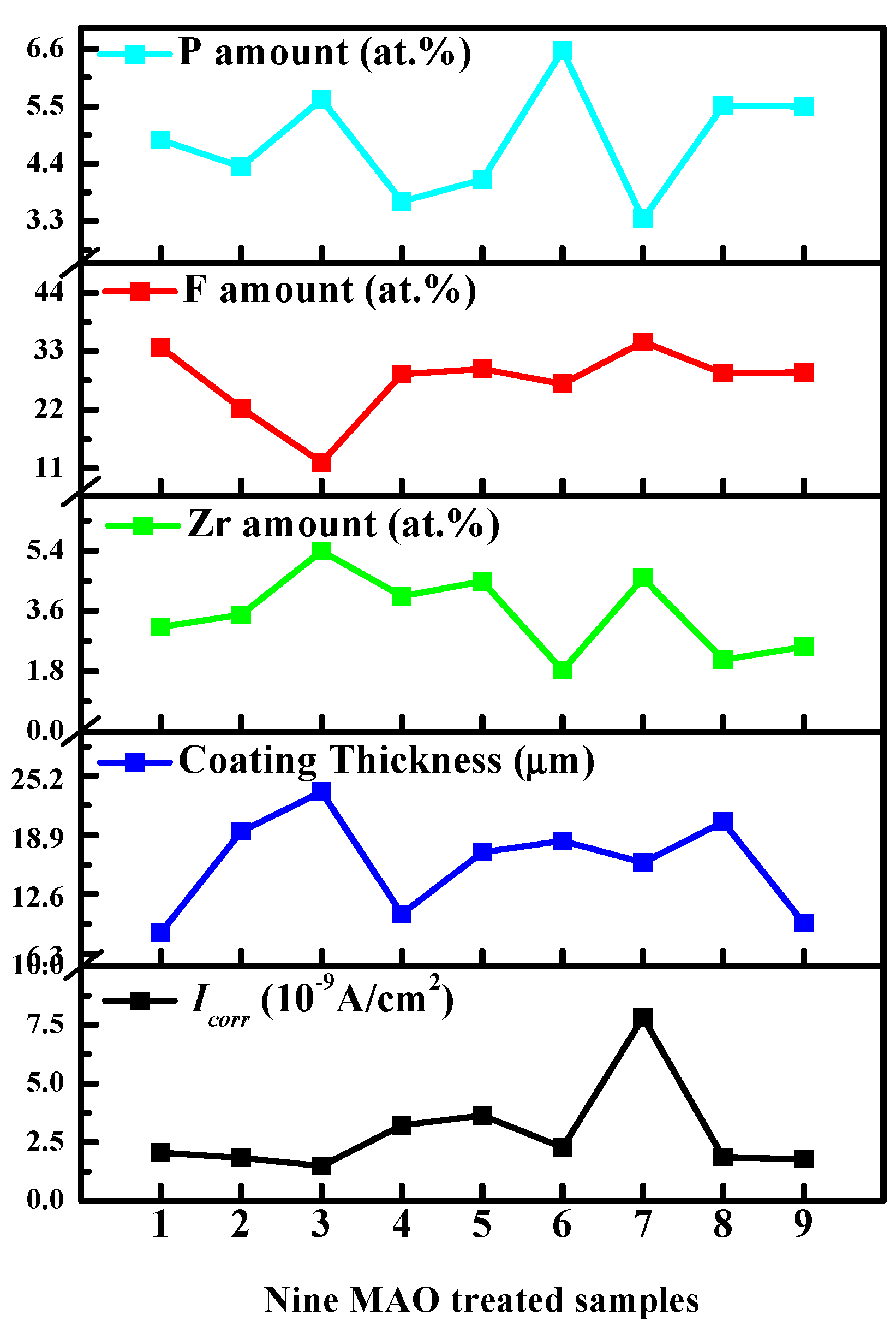
| Process | NH4HF2 (g/L) | Na12Phy (g/L) | K2ZrF6 (g/L) | Treatment Time (min) | P (at.%) | F (at.%) | Zr (at.%) |
|---|---|---|---|---|---|---|---|
| No. 1 | 4 | 8 | 5 | 2.5 | 4.86 | 33.78 | 3.13 |
| No. 2 | 4 | 12 | 10 | 3.0 | 4.34 | 22.29 | 3.49 |
| No. 3 | 4 | 16 | 15 | 3.5 | 5.63 | 12.18 | 5.38 |
| No. 4 | 6 | 8 | 10 | 3.5 | 3.68 | 28.75 | 4.04 |
| No. 5 | 6 | 12 | 15 | 2.5 | 4.09 | 29.71 | 4.48 |
| No. 6 | 6 | 16 | 5 | 3.0 | 6.57 | 26.86 | 1.84 |
| No. 7 | 8 | 8 | 15 | 3.0 | 3.34 | 34.77 | 4.58 |
| No. 8 | 8 | 12 | 5 | 3.5 | 5.51 | 28.92 | 2.15 |
| No. 9 | 8 | 16 | 10 | 2.5 | 5.50 | 29.03 | 2.53 |
| K1 | 14.83 (68.25, 12.00) | 11.88 (97.30, 11.75) | 16.94 (89.56, 7.12) | 14.45 (92.52, 10.14) | |||
| K2 | 14.34 (85.32, 10.36) | 13.94 (80.92, 10.12) | 13.52 (80.07, 10.06) | 14.25 (83.92, 9.91) | |||
| K3 | 14.35 (92.72, 9.26) | 17.70 (68.07, 9.75) | 13.06 (76.66, 14.44) | 14.82 (69.85, 11.57) | |||
| Difference | 0.49 (24.47, 2.74) | 5.82 (29.23, 2.00) | 3.88 (12.90, 7.32) | 0.57 (22.67, 1.66) | |||
| Rank | 4 (2, 2) | 1 (1, 3) | 2 (4, 1) | 3 (3, 4) | |||
| Process | C | O | F | Mg | P | Zr |
|---|---|---|---|---|---|---|
| No. 1 | 8.93 | 28.57 | 33.78 | 19.91 | 4.86 | 3.13 |
| No. 2 | 21.54 | 32.13 | 22.29 | 15.27 | 4.34 | 3.49 |
| No. 3 | 14.98 | 43.93 | 12.18 | 16.64 | 5.63 | 5.38 |
| No. 4 | 15.49 | 28.96 | 28.75 | 18.38 | 3.68 | 4.04 |
| No. 5 | 11.89 | 30.55 | 29.71 | 18.10 | 4.09 | 4.48 |
| No. 6 | 9.23 | 33.50 | 26.86 | 20.96 | 6.57 | 1.84 |
| No. 7 | 9.22 | 27.11 | 34.77 | 20.24 | 3.34 | 4.58 |
| No. 8 | 8.81 | 32.14 | 28.92 | 21.31 | 5.51 | 2.15 |
| No. 9 | 10.47 | 31.48 | 29.03 | 19.92 | 5.50 | 2.53 |
| Process | NH4HF2 (g/L) | Na12Phy (g/L) | K2ZrF6 (g/L) | Treatment Time (min) | Icorr (×10−9 A/cm2) | Thickness (μm) |
|---|---|---|---|---|---|---|
| No. 1 | 4 | 8 | 5 | 2.5 | 2.0548 | 8.5 |
| No. 2 | 4 | 12 | 10 | 3.0 | 1.828 | 19.3 |
| No. 3 | 4 | 16 | 15 | 3.5 | 1.4787 | 23.5 |
| No. 4 | 6 | 8 | 10 | 3.5 | 3.2194 | 10.5 |
| No. 5 | 6 | 12 | 15 | 2.5 | 3.6419 | 17.1 |
| No. 6 | 6 | 16 | 5 | 3.0 | 2.2679 | 18.3 |
| No. 7 | 8 | 8 | 15 | 3.0 | 7.8083 | 16.0 |
| No. 8 | 8 | 12 | 5 | 3.5 | 1.8439 | 20.3 |
| No. 9 | 8 | 16 | 10 | 2.5 | 1.7938 | 9.5 |
| K1 | 5.3615 (51.3) | 13.0825 (35.0) | 6.1666 (47.1) | 7.4905 (35.1) | ||
| K2 | 9.1292 (45.9) | 7.3138 (56.7) | 6.8412 (39.3) | 11.9042 (53.6) | ||
| K3 | 11.446 (45.8) | 5.5404 (51.3) | 12.9289 (56.6) | 6.542 (54.3) | ||
| Difference | 6.0845 (5.5) | 7.5421 (21.7) | 6.7623 (17.3) | 5.3622 (19.2) | ||
| Rank | 3 (4) | 1 (1) | 2 (3) | 4 (2) | ||
© 2019 by the authors. Licensee MDPI, Basel, Switzerland. This article is an open access article distributed under the terms and conditions of the Creative Commons Attribution (CC BY) license (http://creativecommons.org/licenses/by/4.0/).
Share and Cite
Zhu, Y.; Chang, W.; Zhang, S.; Song, Y.; Huang, H.; Zhao, R.; Li, G.; Zhang, R.; Zhang, Y. Investigation on Corrosion Resistance and Formation Mechanism of a P–F–Zr Contained Micro-Arc Oxidation Coating on AZ31B Magnesium Alloy Using an Orthogonal Method. Coatings 2019, 9, 197. https://doi.org/10.3390/coatings9030197
Zhu Y, Chang W, Zhang S, Song Y, Huang H, Zhao R, Li G, Zhang R, Zhang Y. Investigation on Corrosion Resistance and Formation Mechanism of a P–F–Zr Contained Micro-Arc Oxidation Coating on AZ31B Magnesium Alloy Using an Orthogonal Method. Coatings. 2019; 9(3):197. https://doi.org/10.3390/coatings9030197
Chicago/Turabian StyleZhu, Yuanyuan, Wenhui Chang, Shufang Zhang, Yingwei Song, Huade Huang, Rongfang Zhao, Guoqiang Li, Rongfa Zhang, and Yijia Zhang. 2019. "Investigation on Corrosion Resistance and Formation Mechanism of a P–F–Zr Contained Micro-Arc Oxidation Coating on AZ31B Magnesium Alloy Using an Orthogonal Method" Coatings 9, no. 3: 197. https://doi.org/10.3390/coatings9030197
APA StyleZhu, Y., Chang, W., Zhang, S., Song, Y., Huang, H., Zhao, R., Li, G., Zhang, R., & Zhang, Y. (2019). Investigation on Corrosion Resistance and Formation Mechanism of a P–F–Zr Contained Micro-Arc Oxidation Coating on AZ31B Magnesium Alloy Using an Orthogonal Method. Coatings, 9(3), 197. https://doi.org/10.3390/coatings9030197