Article

Investigation on Microstructure, Hardness, and Corrosion Resistance of Mo–Ni–B Coatings Prepared by Laser Cladding Technique

1
College of Mechanical Engineering, Donghua University, Shanghai 201620, China
2
Shanghai Development Research Center of Economy and Internatization, Shanghai 200020, China
3
Research Center of Advanced Textile Machinery, Ministry of Education, Donghua University, Shanghai 201620, China
4
Merchant Marine College, Shanghai Maritime University, Shanghai 201306, China
*
Authors to whom correspondence should be addressed.
Coatings 2019, 9(12), 856; https://doi.org/10.3390/coatings9120856
Submission received: 12 November 2019 / Revised: 2 December 2019 / Accepted: 11 December 2019 / Published: 13 December 2019

Abstract

:
The hard and corrosion resistant coatings of Mo2NiB2 cermet were prepared by the laser cladding technique. The influences of the Mo:B ratio and the laser scanning speed on the microstructure and property of the Mo2NiB2 cermet coatings were investigated. The results showed that the laser scanning speed of 1.5 mm/s and the Mo:B ratio of 1 were more beneficial to the formation of Mo2NiB2 cermet than 2.0 mm/s and 0.8, 1.2, respectively. The amount of the Mo2NiB2 ceramic phases were decreased from the top layer to the bottom layer of the coating. The changes of microstructure and composition led to the changes of hardness and corrosion resistance of the Mo2NiB2 cermet coatings. The coating prepared at the Mo:B ratio of 1 and the scanning speed of 1.5 mm/s possessed the highest hardness, and the hardness gradually decreased from the top layer to the bottom layer of the coating. The formation of Mo2NiB2 and {FeM} phases led to the enhanced corrosion resistance of the Mo2NiB2 cermet coatings, and the coating prepared at the Mo:B ratio of 0.8 possessed the best corrosion resistance and the minimum corrosion current.

1. Introduction

The boride-based cermet composites, especially the transition metal borides cermet composites that consisted of the transition metal and transition metal borides like W2NiB2, WCoB, MoCoB, Mo2FeB2, Mo2NiB2, etc., have been extensively investigated in recent years [1]. The high hardness, melting points, and electrical conductivity of the transition metal borides can endow the cermet composites with the desirable properties including the hardness, melting point, wear and corrosion resistance, and optical and thermal performances [2,3,4,5]. These boride cermet composites have already been used in wear and corrosion-resistant fields like bearings for sea water pumps, injection molding machine parts, and offshore engineering parts [6,7].
Recently, as emerging and promising boride-based materials with superior strength, hardness, wear, and corrosion resistance, the Mo2NiB2 cermet coatings comprised of Ni metal and the dispersed Mo2NiB2 phases have attracted lots of scientific interest [8,9,10,11,12,13,14]. Yuan et al. [11] utilized reaction sintering method to prepare the Mo2NiB2 cermet and found that the hardness and bending strength of Mo2NiB2 cermet could reach 85.7 HRA and 1.85 GPa, respectively. In addition, the hardness and transverse rupture strength (TRS) could be further enhanced by adding Cr element [12]. Takagi et al. [1,10,12] also prepared Mo2NiB2 cermet by reaction boronizing sintering and found that the TRS and hardness of the Mo2NiB2 cermet were 2.35 GPa and 84.5 HRA, respectively. Plus, the addition of Cr and V elements further enhanced the TRS, hardness, and corrosion resistance of the Mo2NiB2 cermet. Besides the reaction sintering method, other methods like high-velocity oxy-fuel (HVOF), plasma spraying, detonation gun spraying and laser cladding, etc., can also provide high energy for the reactive synthesis of Mo2NiB2 cermet coatings [15,16,17,18,19]. Nonetheless, each method has its own characteristics, which induces the significantly different effects of the methods on the Mo2NiB2 cermet coatings. Among these synthesis methods, the laser cladding technique possesses superior properties like environmental friendship, good artificial controllability, high efficiency and energy, and convenience [20]. Thus, the laser cladding technique is the desirable and excellent method to fabricate the Mo2NiB2 cermet coatings, which has been applied in the preparation of the Mo2NiB2 cermet coatings. Hu et al. [14] prepared the Mo2NiB2 (M3B2) cermet coatings by laser cladding and found that the pretreatment and re-melting afterwards could greatly affect the microstructure and properties of the coatings. Wu et al. [13] found that laser cladding fabricated Mo2NiB2 cermet coatings possessed high hardness, good wear and corrosion resistance. However, these works mainly focused on the preparation and property characterization of Mo2NiB2 cermet coatings, and how the laser cladding parameters influenced the property were not deeply discussed. Therefore, the comprehensive investigations on the influences of the laser cladding process on the microstructure and property of Mo2NiB2 cermet coatings are quite needed, which is beneficial for widening the application of Mo2NiB2 cermet coatings.
Herein, as the important cladding parameters, the laser scanning speed and the raw materials composition were investigated to illustrate the influences of the cladding parameters on the microstructure and property of Mo2NiB2 cermet coatings. Firstly, the Mo2NiB2 cermet coatings were prepared on Q235 steels using the laser cladding technique with the different scanning speeds and the various raw materials composition. Secondly, the hardness and corrosion resistance (corrosion potential and corrosion current) of the coatings were evaluated. Finally, how the laser cladding parameters influence the microstructure and property of Mo2NiB2 cermet coatings were illuminated.

2. Preparation and Characterization

2.1. Preparation of the Mo2NiB2 Cermet Coatings

The Mo2NiB2 cermet coatings were synthesized with Mo, Ni, B, Cr powders using laser cladding technique. The average size of the powders was ca 45 μm. The Q235 steels (C 0.14 wt.%–0.22 wt.%, Mn 0.3 wt.%–0.65 wt.%, Si ≤ 0.3 wt.%, S ≤ 0.05 wt.%, and P ≤ 0.045 wt.%) worked as the substrate with a size of 100 mm × 80 mm × 10 mm. The various molar ratios of Mo and B (Mo:B ratio) containing 10 wt.% Cr powder in totally mixed particles were utilized to synthesize the Mo2NiB2 cermet coatings using a laser machine (SLC-20×30D, Shanghai Unityprima Laser Equipment Ltd., Shanghai, China). The different laser scanning speeds were adopted with the laser spot size of 6 mm × 1 mm. The detailed laser cladding parameters are listed in Table 1.
Before cladding procedure, the substrates of Q235 steels were sandblasted for 10 min to remove the contaminants like dust, rust and oil, then the substrates were cleaned with ultrasonic treatment for 10 min. The mixed particles of Mo, Ni, B, and Cr with polyvinyl butyral (PVB) binder were ballmilled for 2 h. After that, the mixed particles were preset on the surface of the cleaned substrates, and the thickness of the preset layer reached ca 1 mm. After preparation, the coated specimens were cut into some small specimens with the size of 10 mm × 10 mm × 10 mm, then they were degreased with acetone and cleaned with deionized water for further characterization.

2.2. Characterization of the Mo2NiB2 Cermet Coatings

The phase compositions of the prepared Mo2NiB2 cermet coatings were analyzed by X-ray diffraction (XRD, X’Pert PRO, Panalytical, Almelo, The Netherlands) with Cu-Kα radiation (λ = 0.154 nm) operated at 2.2 kW. The detected diffraction angle (2θ) was scanned from 20° to 100° and the scanning speed was 5°/min. The microstructure and composition distribution of the Mo2NiB2 cermet coatings were characterized by the metallurgical microscopy (Ti-E, Nikon, Tokyo, Japan) and scanning electron microscopy (SEM, JSM7500F, Jeol, Tokyo, Japan) with energy-dispersive X-ray spectroscopy (EDS, Swift 3000, Oxford instruments, Oxford, UK).
The surface conditions of the Mo2NiB2 cermet coatings were characterized by an optical microscope (Contour-X8, Bruker, Berlin, Germany). The hardness of the cross-section of the Mo2NiB2 cermet coatings were measured by a Rockwell hardness tester (HXD-1000TMC, Shanghai TaiMing, Shanghai, China) with 200 gf loading and dwell time of 10 s. The corrosion behaviors of the coatings were analyzed by an electrochemical workstation (RST-5200, Shiruisi instruments, Zhengzhou, China) in 1 mol/L HCl solution at room temperature. The coated specimens with exposed area of 1 cm2, pure platinum plate and saturated calomel electrode (SCE) worked as the working electrode, counter electrode and reference electrode of the standard three-electrode system, respectively. The electrochemical impedance spectra (EIS) were measured with a potential amplitude of 10 mV and a frequency of 0.01 to 10,000 Hz after immersing in 1 mol/L HCl solution for 1 week. Potentiodynamic polarization experiments were also carried out at a scanning speed of 1 mV/s, and corrosion potential (Ecorr) and corrosion current (Icorr) were obtained by the Tafel extrapolation method. In experiments, the corrosion behaviors of corrosion-resistant 304 stainless steel (C ≤ 0.07 wt.%, Cr 17.0 wt.%–19.0 wt.%, Ni 8.0 wt.%–11.0 wt.%, Mn ≤ 2.0 wt.%, Si ≤ 1.0 wt.%, S ≤ 0.03 wt.%, and P ≤ 0.035 wt.%) and low alloy steel (C 0.12 wt.%–0.20 wt.%, Mn 1.3 wt.%–1.6 wt.%, Si 0.40 wt.%–0.60 wt.%, S ≤ 0.04 wt.%, and P ≤ 0.04 wt.%) were also investigated at the same experimental conditions. Comparing with the 304 stainless steel and low alloy steel, the corrosion behaviors of the Mo2NiB2 cermet coatings could be deeply understood.

3. Results

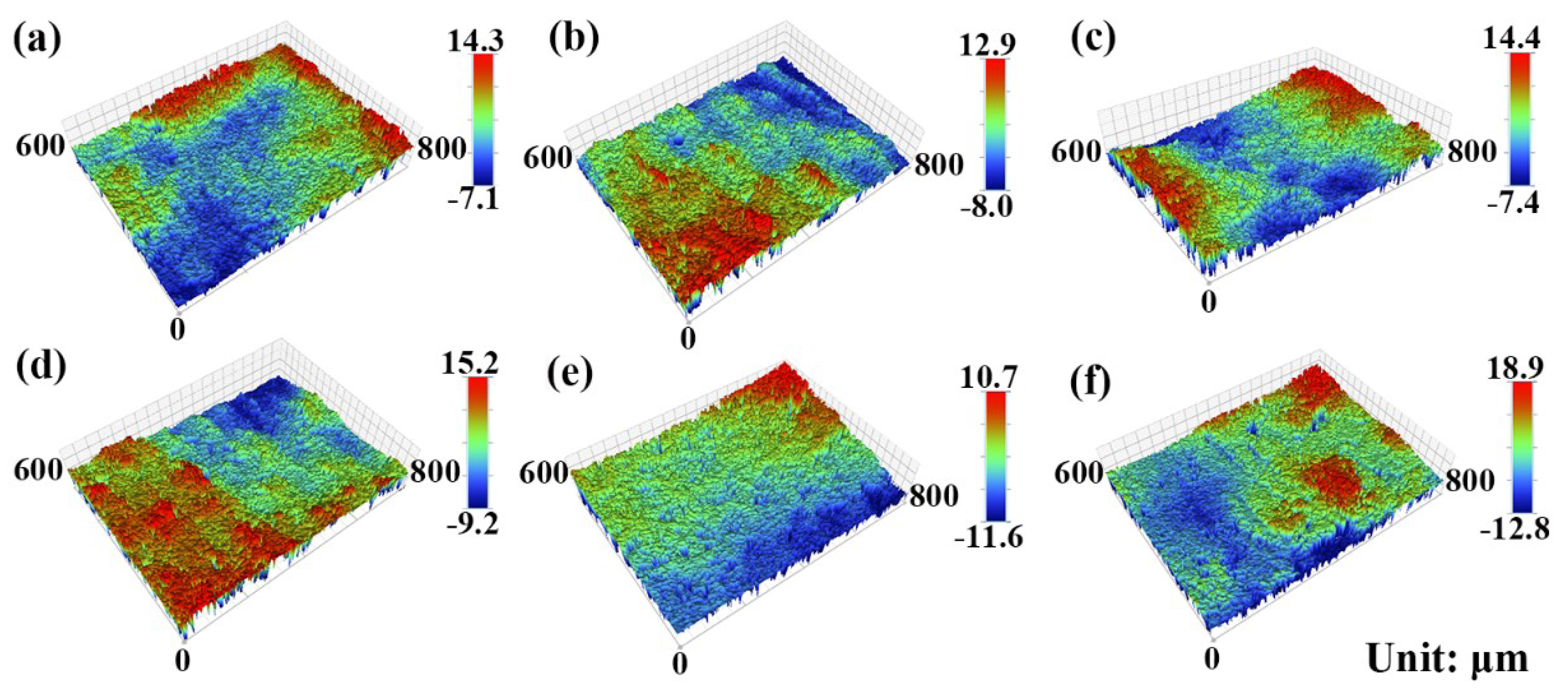
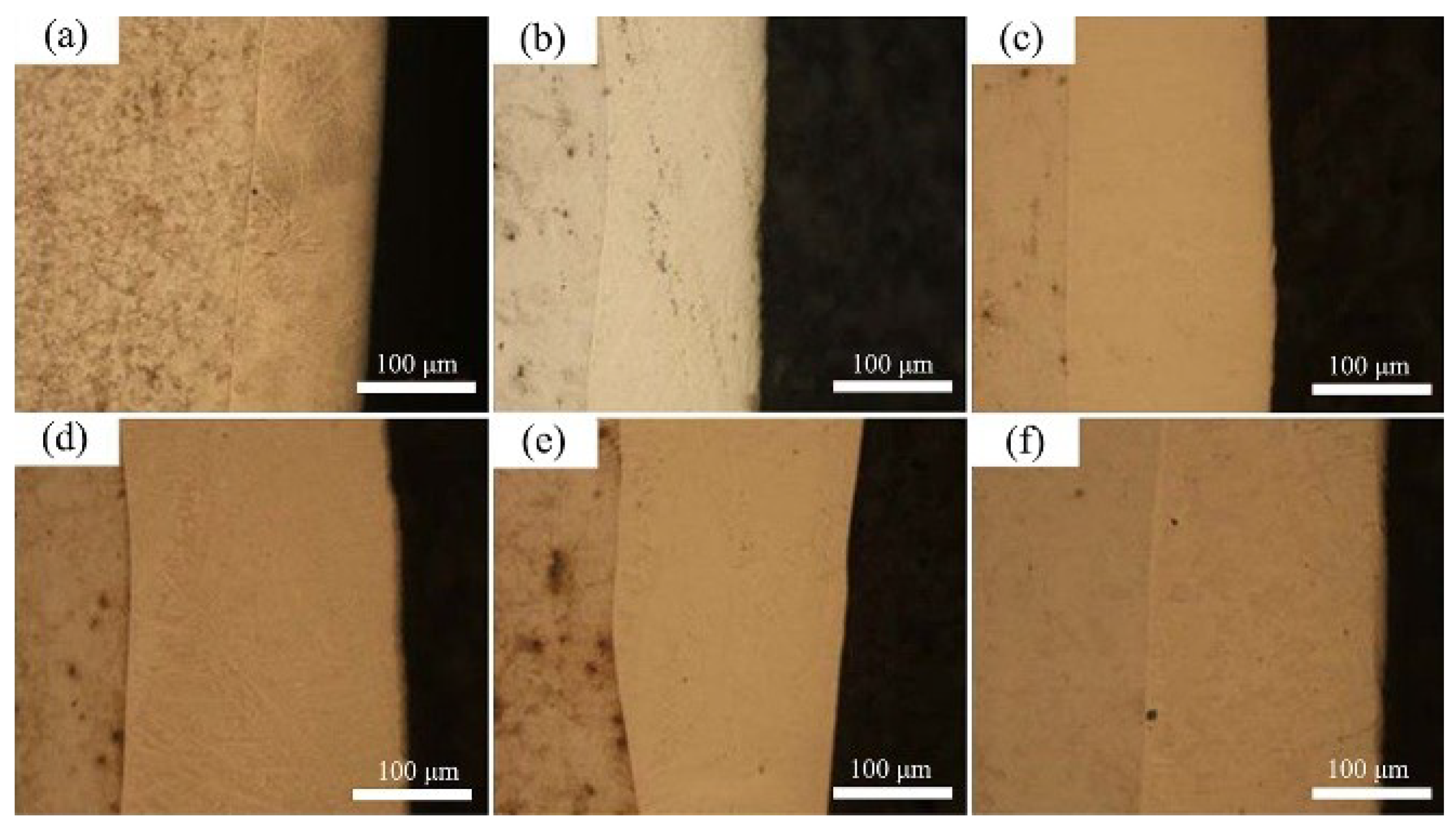
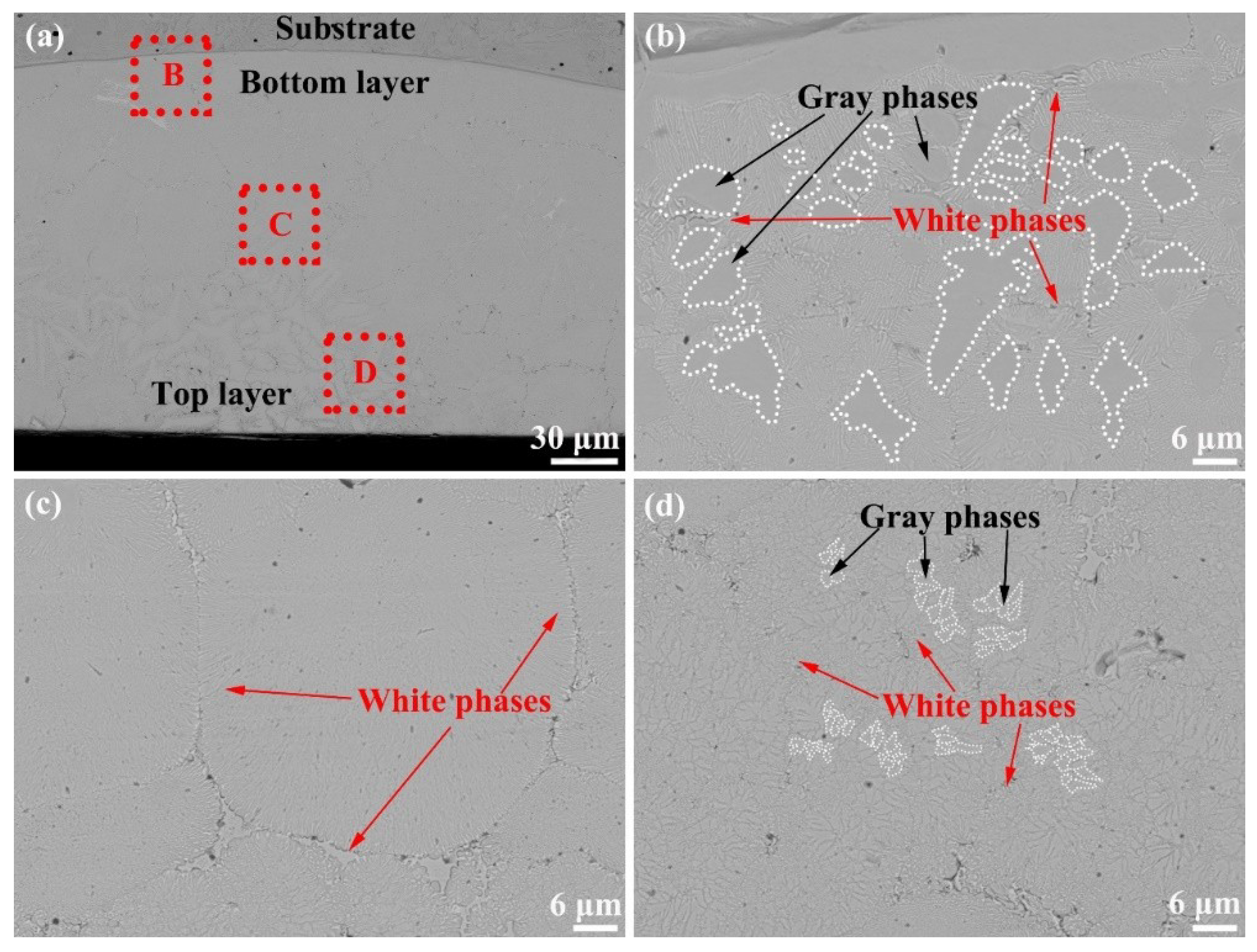
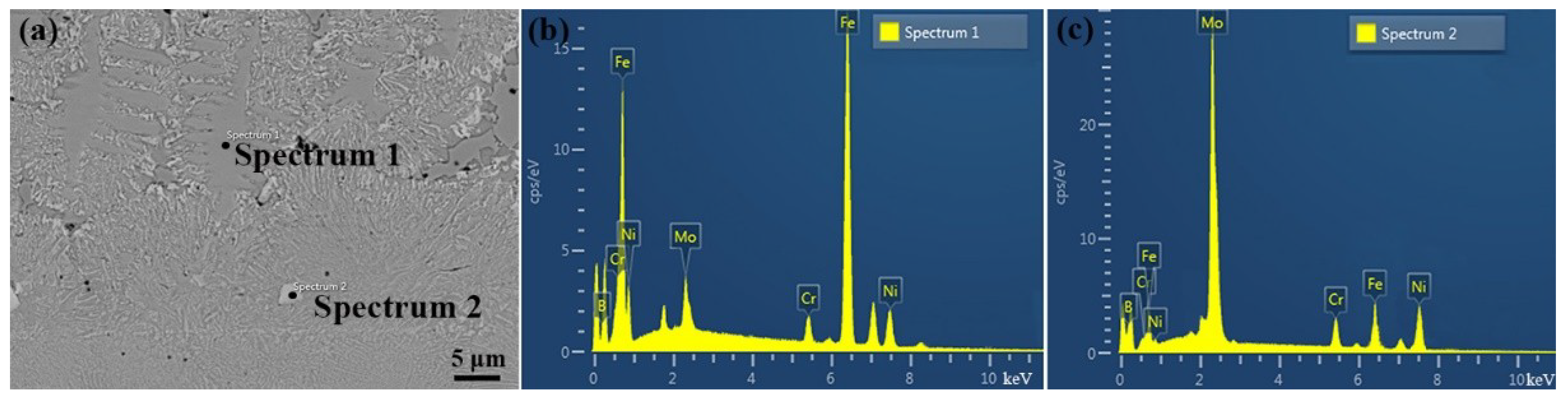
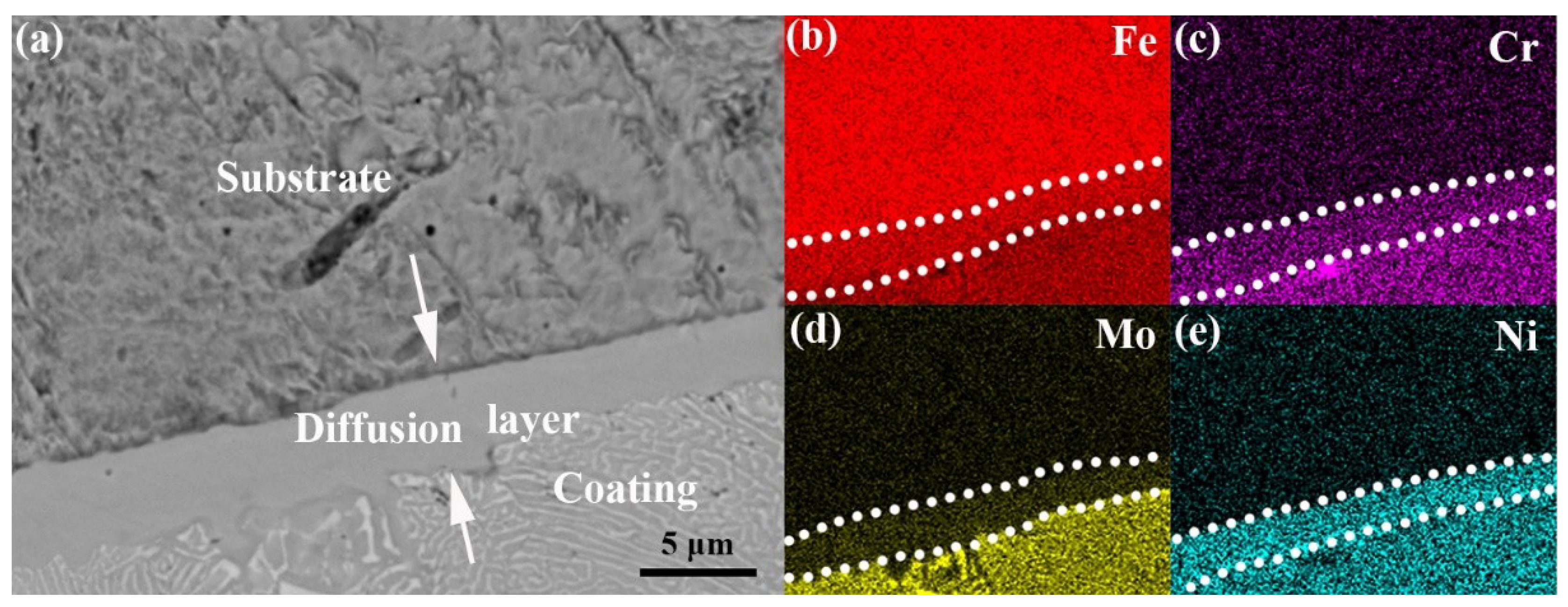
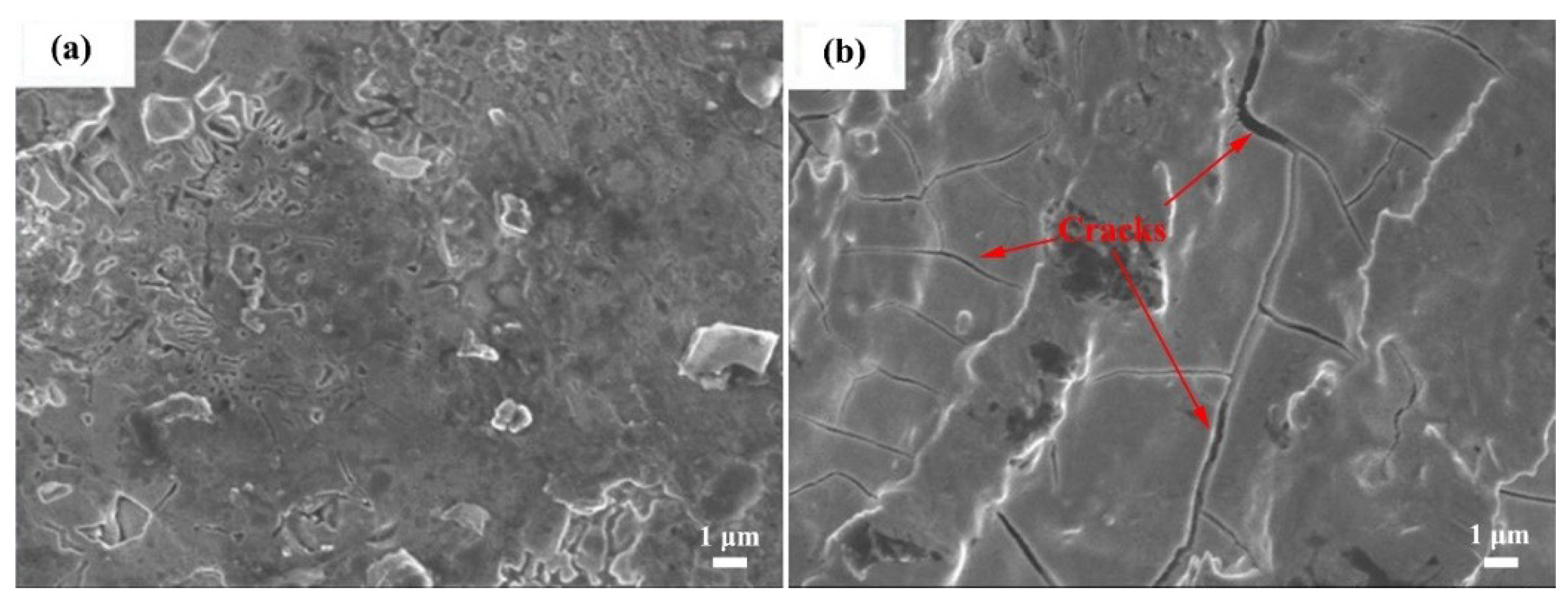
3.1. Composition and Microstructure of the Mo2NiB2 Cermet Coatings

The 3D surface morphologies of the Mo2NiB2 cermet coatings are exhibited in Figure 1. It is observed that the surface condition of a given coating is nonuniform, which has a certain surface roughness. The maximum surface roughness (31.7 μm) appears in the coating prepared at the Mo:B ratio of 1.2 and the scanning speed of 2 mm/s, while the coating prepared at the Mo:B ratio of 1 and the scanning speed of 1.5 mm/s has the minimum roughness of 20.9 μm. Having a careful observation, it is found that the surface roughness of the coatings prepared at 1.5 mm/s are lower than at 2 mm/s. In addition, the relative low surface roughness of all the coatings suggest that the selected lapping distance of 1 mm is an appropriate laser cladding parameter in this work.
The XRD results of the prepared coatings are exhibited in Figure 2, and the Mo2NiB2 ceramic phase and {FeM} alloy phase are found in all XRD patterns. The {FeM} alloy phase is the solid solution based on the crystalline structure of Fe, and the M represents the elements of Ni, Mo and Cr. It is observed that the different laser cladding parameters have various influences on the XRD profiles of the coatings. With respect to the Mo:B ratio, the intensities of Mo2NiB2 peaks in coatings prepared at Mo:B ratio of 1 are always the strongest, no matter the scanning speed of 1.5 or 2.0 mm/s. Meanwhile, the peak intensities of Mo2NiB2 in coatings prepared at 1.5 mm/s are stronger than 2 mm/s for all the coatings. Thus, the peak intensity of Mo2NiB2 in the coating prepared at the Mo:B ratio of 1 and the scanning speed of 1.5 mm/s is the strongest one as shown in Figure 2b.
The cross-sectional morpholgies of the Mo2NiB2 cermet coatings are exhibited in Figure 3. It further verifies that the suface roughness of all the coatings are low, and the thickness of a given coating is almost uniform in the whole coating except the coating prepared at the Mo:B ratio of 1 and the scanning speed of 2 mm/s (see Figure 3e). In addition, the nonuniform thickness of the coating is caused by the irregular surface of the substrate. Nonetheless, it can be carefully found that the thicknesses of all the coatings prepared at 1.5 mm/s are smaller than 2 mm/s. The enlarged cross-sectional morphology of the coating prepared at the Mo:B ratio of 1 and the scanning speed of 1.5 mm/s are exhibited in Figure 4. Lots of white phases are abundantly distributed in the whole coating. Apparently, the amount of the white phases gradually decreases from the top layer to the bottom layer of the coating (see Figure 4b–d), which are 82%, 73% and 68% obtained by quantitative metallography method, respectively. The sizes of the dispersed gray phases in the top layer of the coating are obviously smaller than those in the bottom layer of the coating.
The compositions of the white and gray phases in the coating prepared at the Mo:B ratio of 1 and the scanning speed of 1.5 mm/s were examined by EDS and the results are shown in Figure 5. The EDS profiles of the locations 1 and 2 are apparently different from each other as shown in Figure 5b,c, indicating the different element contents in two locations. In location 1, the content of Fe is much higher than others, whereas the content of Fe is greatly reduced and more Mo is detected in location 2. The detailed element contents are given in Table 2. It is observed that the gray phase possess the Fe element of 74.5 wt.% without B in location 1. In location 2, the content of Fe is reduced to 12.3 wt.%, and the contents of Mo, Ni, and B reach 55.9 wt.%, 24.2 wt.% and 4.8 wt.%, respectively. This suggests that the gray phase in location 1 is the {FeM} phase and the white phase mainly is the Mo2NiB2 phase corresponding to the results of XRD.
The element mapping of the interlayer between the Q235 substrate and the Mo2NiB2 cermet coating are exhibited in Figure 6. It is observed that there is not a visible gap existing between the prepared coating and Q235 substrate. In addition, from the substrate to the coating, the distribution of all the Fe, Ni, Cr and Mo elements are gradually changed without sudden break. Lots of Fe, Ni, Cr and Mo elements exist in the interlayer of ca 4 μm thickness between the substrate and the coating, which can lead to the formation of the diffusion layer.

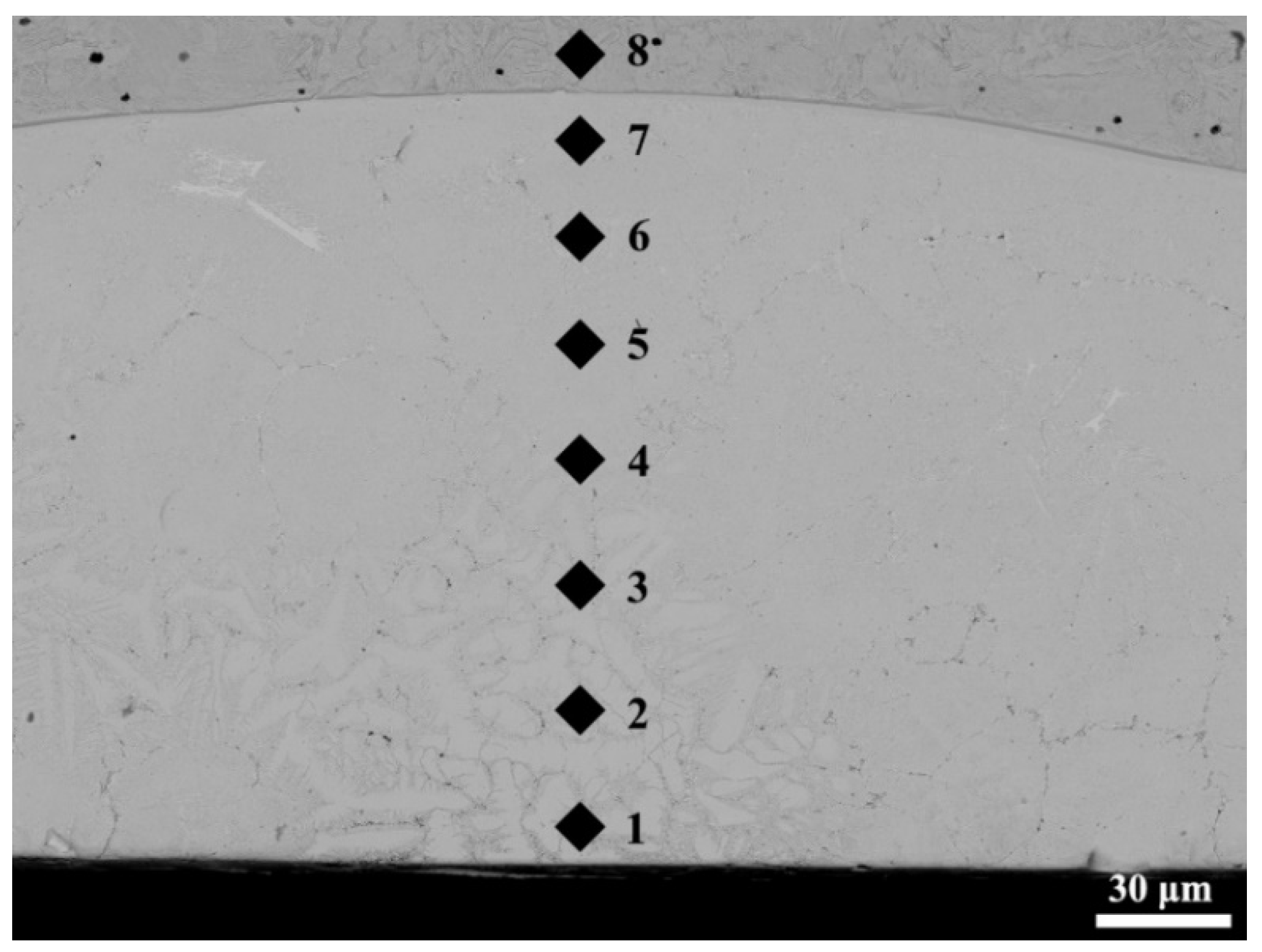
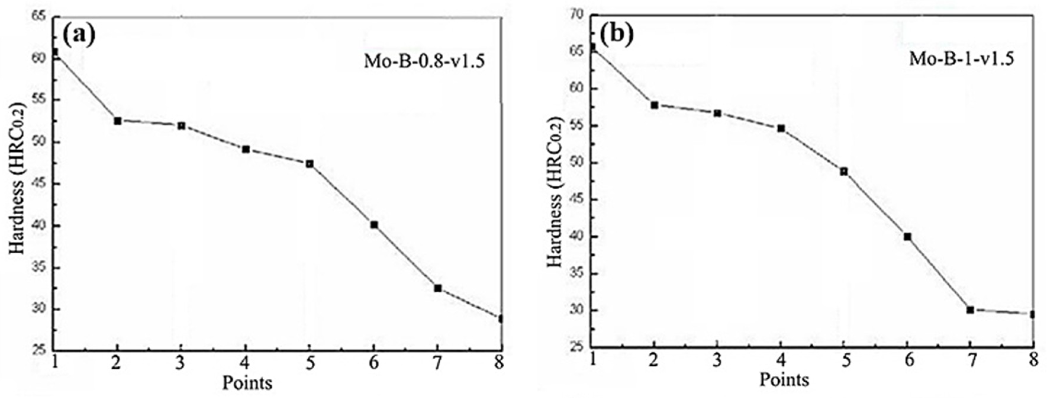
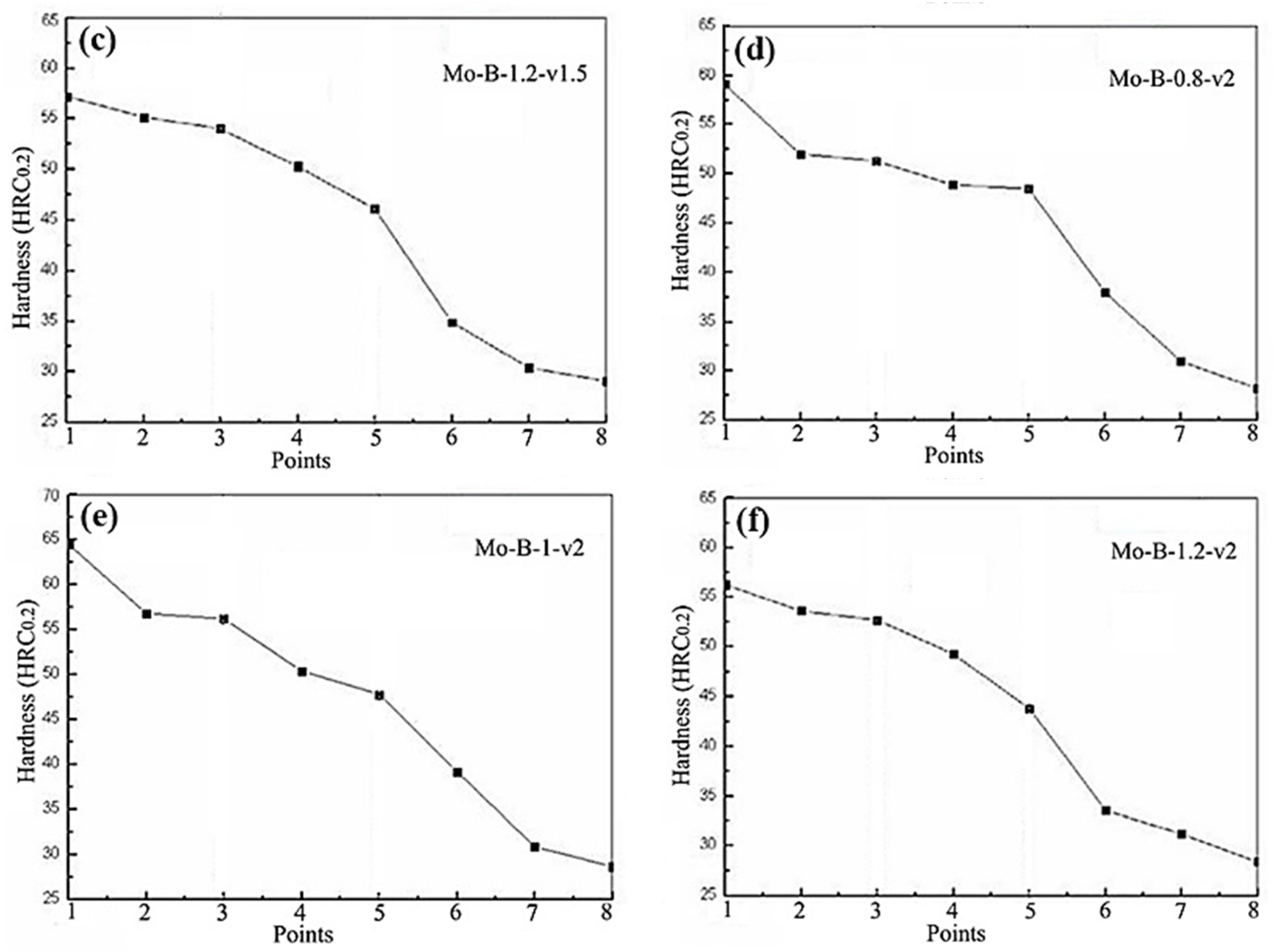
3.2. Hardness of the Mo2NiB2 Cermet Coatings

In the hardness testing, eight points were tested on the cross section of the Mo2NiB2 cermet coatings as shown in Figure 7. These eight points range from the Q235 substrate to the top layers of the Mo2NiB2 cermet coatings. The results of hardness distribution are exhibited in Figure 8. It is observed that the hardness of all the coatings gradually decrease from the top layer to the bottom layer, and their hardness evolution curves are similar to each other. The hardness of the coatings are much higher than that of the Q235 substrate, which indicates the optimization effects of the prepared coatings on the hardness of Q235 steels. Nevertheless, having a careful view of the figures, the slight differences in the hardness distribution can be found. Comparing with the scanning speed of 2.0 mm/s, the speed of 1.5 mm/s is more beneficial to the improvement of the hardness of the Mo2NiB2 cermet coatings, no matter the Mo:B ratios of 0.8, 1 or 1.2. With regard to the Mo:B ratios, the hardness of the coating prepared at the Mo:B ratio of 1 is slightly higher than that of the coatings prepared at the ratios of 0.8 and 1.2 for both 1.5 and 2.0 mm/s, respectively.

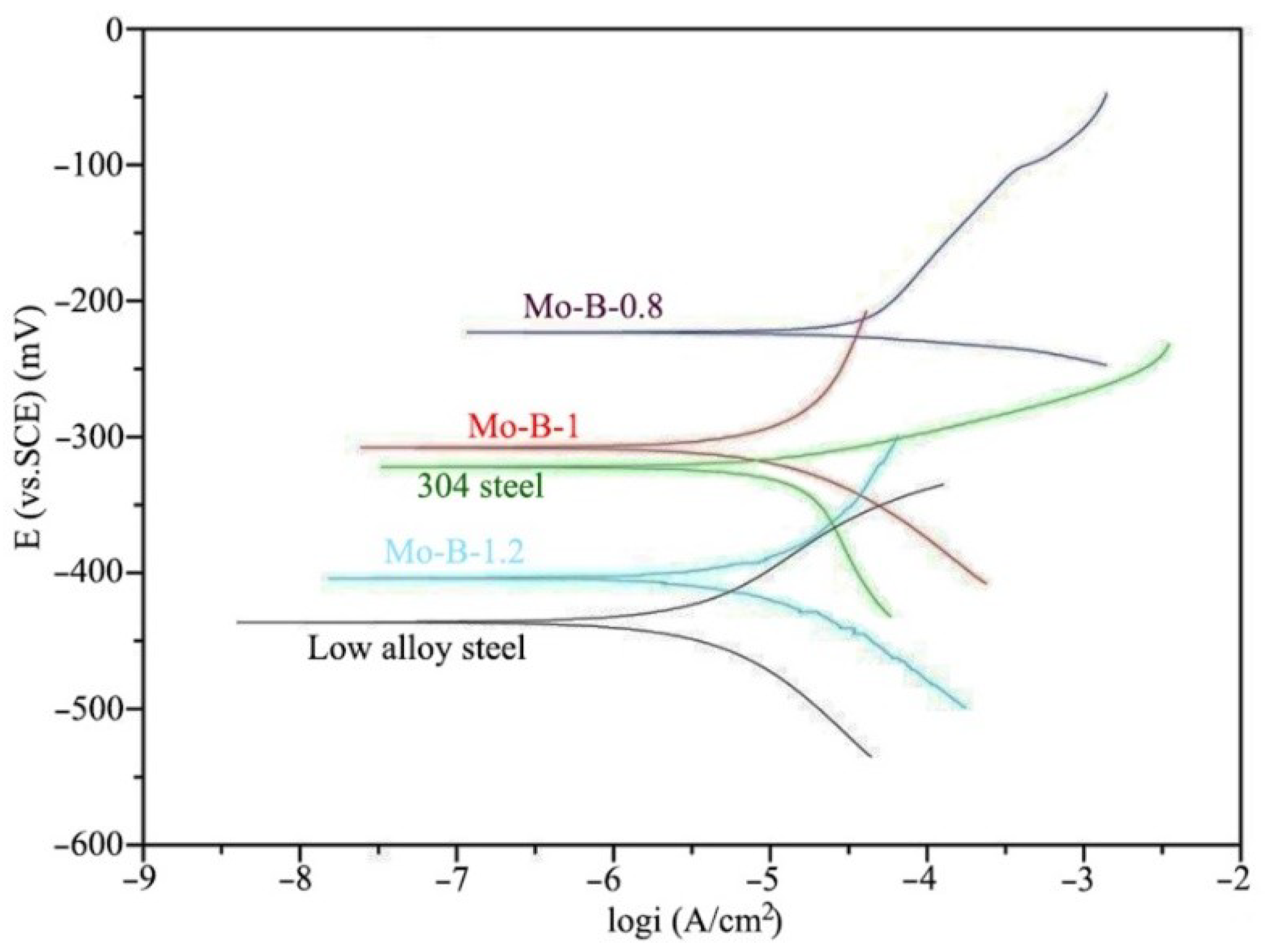
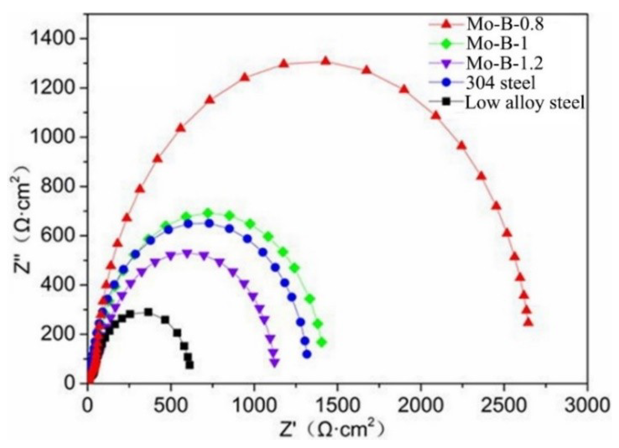
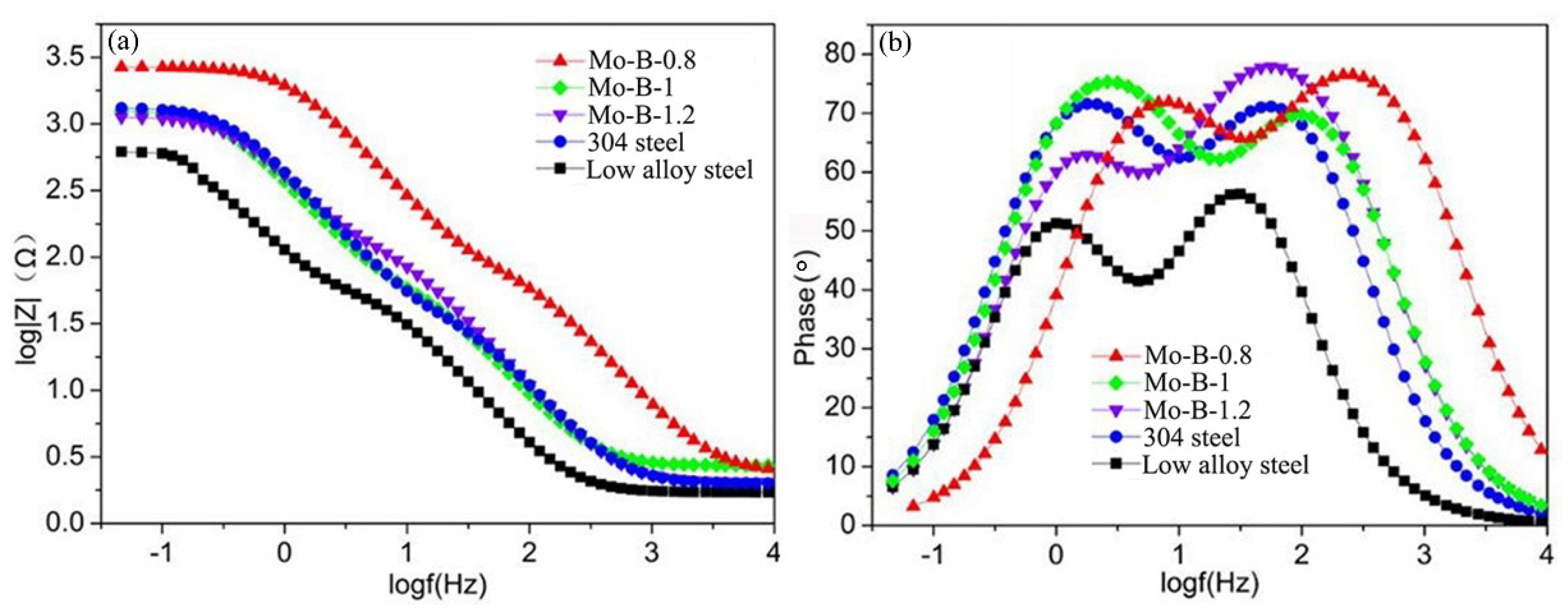
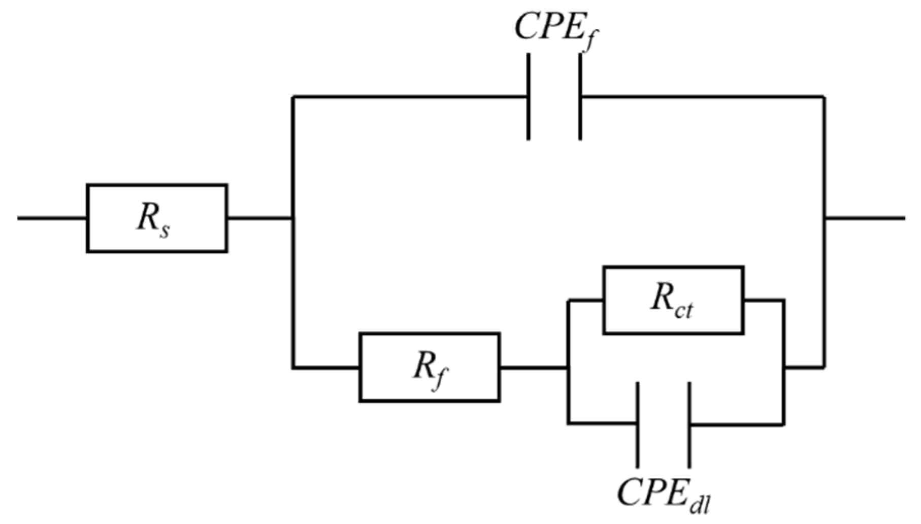
3.3. Corrosion Behaviors of the Mo2NiB2 Cermet Coatings

The Mo2NiB2 cermet coatings prepared at the laser scanning speed of 1.5 mm/s were selected to evaluate the effects of the Mo:B ratio on the corrosion behaviors of the coatings. This was because the low laser scanning speed favored the formation of the Mo2NiB2 ceramic by supplying high reaction energy, which normally contributed to the enhanced corrosion resistance of the coatings [13,14]. The potentiodynamic polarization curves of all the testing materials are exhibited in Figure 9. It is apparently seen that the differences in Ecorr are not significant between the prepared Mo2NiB2 cermet coatings and 304 steel, whereas they are more positive than that of the low alloy steel. The Ecorr of the coating prepared at Mo:B ratio of 0.8 is the most positive one. The calculated corrosion factors including Ecorr and Icorr of all the testing materials by Tafel extrapolation method are listed in Table 3. βa and βc represent the slope values of the anodic and cathodic polarization curves, respectively. The Icorr values of the Mo2NiB2 cermet coatings are similar to that of the 304 steel and much lower than that of the low alloy steel. With increasing the Mo:B ratio, the Ecorr of the Mo2NiB2 cermet coatings gradually decreases and the Icorr increases, just the opposite. The Mo2NiB2 cermet coating prepared at Mo:B ratio of 0.8 possesses the highest Ecorr of −223.2 mV and the lowest Icorr of 1.58 × 10⁻⁵ A/cm2.
The Nyquist plots of all the testing materials are exhibited in Figure 10. It is observed that the Nyquist plots of all the materials exhibit the single semicircle and the semicircle diameter of the Mo2NiB2 cermet coating increases when Mo:B ratio decreases. The semicircle diameters of the Mo2NiB2 cermet coatings are much larger than that of the low alloy steel and not significantly different from that of 304 steel. The Mo2NiB2 cermet coating prepared at the Mo:B ratio of 0.8 has the largest diameter, which indicates the best corrosion resistance of the coating.
The Bode plots, which consisted of the Bode phase plot and Bode impedance plot of all the testing materials are exhibited in Figure 11. In Figure 11a of the Bode impedance plots, the corrosion resistance of the materials can be evaluated by the value of the Z, which represents the value of impedance magnitude [21]. The larger the value of Z is, the better the corrosion resistance of the material. Thus, it is clear that the corrosion resistance of the Mo2NiB2 cermet coating prepared at Mo:B ratio of 0.8 is the best one and the worst one is the low alloy steel. In Figure 11b of the Bode phase plots, the Bode phase angles represent the corrosion system time constants, which suggests two-time constants for all the testing materials. In addition, the equivalent circuit model is shown in Figure 12, in which Rs is the solution resistance, Rf is the surface layer resistance, CPEf is the constant phase angle element between the corrosion media and the surface, CPEdl is the non-ideal double-layer capacitance of the materials and Rct is the charge transfer resistance at the materials HCl solution interface, which reflects the corrosion rate of materials inversely [22]. The calculated values of the elements in the equivalent circuit model are listed in Table 4. It is observed that the Rct values of the Mo2NiB2 cermet coatings are larger than that of the low alloy steel, and the coating prepared at Mo:B ratio of 0.8 has the maximum Rct value of 2153 Ω·cm2, indicating the best corrosion resistance of the coating. The EIS results are almost consistent with the results of potentiodynamic polarization experiments.
After corrosion, the surface morphologies of the Mo2NiB2 cermet coatings prepared at Mo:B ratios of 0.8 and 1 were compared to explore the different corrosion behaviors of the coatings as shown in Figure 13. It is observed that few corrosion pitting and cracks appear on the surface of the coating prepared at the Mo:B ratio of 0.8. Whereas, some large-sized corrosion cracks present on the surface of the coating prepared at the Mo:B ratio of 1, which suggests severe corrosion is happening to the coating during the corrosion experiments.

4. Discussion

From the 3D surface morphologies of the Mo2NiB2 cermet coatings, as shown in Figure 1, it is found that the coatings prepared at 1.5 mm/s have a lower surface roughness compared to 2 mm/s. This was caused by the more laser energy supply from the scanning speed of 1.5 mm/s. High laser energy could enhance the liquidity of the molten powders and consequently optimized the surface smoothness of the coatings. In Figure 2 of the XRD patterns, the formation of the Mo2NiB2 ceramic phases were derived from the reaction of the raw particles during the laser cladding processing [13,14]. The formation of the {FeM} metal phases were induced by the intense diffusion of molten metals. The Mo2NiB2 phase in the coating prepared at the Mo:B ratio of 1 and the scanning speed of 1.5 mm/s possessed the strongest peak intensity, suggesting the highest content of the Mo2NiB2 phases in the coating.
The thicknesses of all the coatings prepared at 1.5 mm/s are smaller than 2 mm/s (see Figure 3), which was caused by the formation of defects like porosity, unmolten or semimolten particles during the laser cladding processing. With the high scanning speed, the reaction synthesis process of the coating was not fully achieved without the supply of enough energy, which induced lots of undesirable defects and a consequent increase in the thickness of the prepared coatings. In the cross section of the coating, the nonuniform distribution of the white phases (see Figure 4) was caused by the out diffusion of the Fe elements derived from the substrate steels during laser cladding processing [14]. The small size of the dispersed gray phase of {FeM} in the top layer was induced by the uniform distribution of the fine white phase of Mo2NiB2 during the solidification of the cermet coatings. Furthermore, as the nucleation sites for the {FeM} phase, the fine Mo2NiB2 ceramic phase could give birth to the grain refinement of the {FeM} phase during the solidification [14]. Therefore, it was rational to consider that the grain size of the {FeM} in the top layer was smaller than that in the bottom layer.
The EDS results as shown in Figure 5 and Table 2 indicated that the gray phase, which consisted of Fe, Ni, Cr and Mo was the {FeM} phase in location 1, and the white phase, which mainly consisted of Mo, Ni and B was the Mo2NiB2 phase in location 2. Especially in location 2, it was rational to consider that the distributed white phases mainly consisted of Mo2NiB2, although some Fe and Cr atoms occupied the locations which originally belonged to Ni atoms. In addition, these results were consistent with the related literatures which confirmed the Mo2NiB2 as the dispersed ceramic phases [13,14,23].
The element mapping of the interlayer between the substrate and the Mo2NiB2 cermet coating as shown in Figure 6 suggested that the interlayer was a kind of diffusion layer, in which the alloying phases of Fe, Ni, Cr and Mo elements were formed. The formation of the diffusion layer indicated the metallurgical bonding between the coating and substrate, which provided strong adhesion of the Mo2NiB2 cermet coating to the substrate.
The differences in the hardness distribution among the Mo2NiB2 cermet coatings (see Figure 7) were induced by the various microstructure and composition of the coatings, which could be explained by the second phase strengthening and grain refinement strengthening mechanisms [24,25]. The grain refinement strengthening based on Hall-Petch formula gave an important contribution [25]:
    σ y = σ 0 + k d 1 / 2
Hardness = 3 σ y
where σ0 is a friction stress, σy is the yield stress, d is crystallite size and k is a constant. The second phase strengthening based on the amount of the hard second phases could also contribute to the enhancement of the hardness of the coatings [24]. Herein, under the Mo:B ratio of 1 and scanning speed of 1.5 mm/s, a large number of Mo2NiB2 ceramic phases could be synthesized due to enough laser energy supply. Then, the generated Mo2NiB2 ceramic phases could work as the nucleation sites for the {FeM} phases, which induced the grain refinement of {FeM} phases in the coating. In addition, the more ceramic phases that were generated, the more grain refinement of the {FeM} phases that happened. Thus, the Mo2NiB2 cermet coatings prepared at the Mo:B ratio of 1 and the scanning speed of 1.5 mm/s possessed the highest content of Mo2NiB2 phases and the smallest grain size of the {FeM} phases, which led to high hardness of the coating. For a given coating, the decreasing trend of hardness was caused by the decrease in the content of Mo2NiB2 phases from the top layer to the bottom layer of the coating.
In the experiments of potentiodynamic polarization and EIS, the good corrosion resistance of the Mo2NiB2 cermet coatings were attributed to the formation of the Mo2NiB2 ceramic phases and the {FeM} phases. The Mo2NiB2 ceramic phases on the surface of the coating could reduce the exposure area of the {FeM} metal phases in HCl solution, and then easily led to the anode polarization and the decrease of corrosion current [21,22]. The Mo2NiB2 ceramic phases also worked as the “physical barrier” to hinder the corrosion extending in the coatings [22]. Besides, as mentioned above, the Mo2NiB2 ceramic phases led to the grain refinement of the {FeM} phases. The decreased grain sizes of the {FeM} phases could lengthen the corrosion path and then reduced the corrosion rate of the coating [26]. Therefore, the formation of the Mo2NiB2 phases and the {FeM} phases enhanced the corrosion resistance of the Mo2NiB2 cermet coatings.
As discussed above, it was rational to conclude that more Mo2NiB2 phases would contribute to the better corrosion resistance of the coating. However, in this work, the corrosion resistance of the Mo2NiB2 cermet coating prepared at Mo:B ratio of 1 with the largest amount of Mo2NiB2 ceramic phases was unexpectedly worse than that of the coating prepared at Mo:B ratio of 0.8. By comparing the corrosion morphologies of these two kinds of coatings (see Figure 13), it was observed that severe corrosion cracks appeared on the surface of the coating prepared at the Mo:B ratio of 1, which indicated that severe corrosion took place and the corrosion resistance of the coating was reduced. Herein, the decreased grain sizes of {FeM} phases were the double-edged sword to the corrosion resistance of the coatings. The decreased grain sizes could increase the possibility of the corrosion occurring at the grain boundary, which decreased the corrosion resistance of the coating prepared at Mo:B ratio of 1 [21,22,26].

5. Conclusions

The Mo2NiB2 cermet coatings were successfully synthesized on Q235 steels by laser cladding technique with different Mo:B ratios and laser scanning speeds. These two kinds of laser cladding parameters had significant effects on the microstructure and property of the Mo2NiB2 cermet coatings. With increasing the laser scanning speed from 1.5 to 2.0 mm/s, the amount of synthesized Mo2NiB2 ceramic phases was reduced due to the decrease in the supply of laser energy, and the Mo:B ratio of 1 more favored the formation of the Mo2NiB2 phases. However, the distribution of the ceramic phases in the coatings were not uniform, which decreased from the top layer to the bottom layer of the coatings.
The microstructure evolution led to the changes of hardness and corrosion resistance of the Mo2NiB2 cermet coatings. For a given coating, the hardness of cross section of the coatings decreased from the top layer to the bottom layer, which were much higher than that of Q235 steels. The corrosion resistance of the Mo2NiB2 cermet coatings were always much better than that of the reference low alloy steels, and the Icorr was decreased by one order of magnitude. The Mo2NiB2 cermet coating prepared at Mo:B ratio of 0.8 possessed the best corrosion resistance. The enhanced corrosion resistance of the coatings were attributed to the formation of the Mo2NiB2 and {FeM} phases.

Author Contributions

Data curation, X.N. and X.J.; formal analysis, X.N. and X.J.; investigation, X.N. and X.J.; writing–original draft preparation, X.N.; funding acquisition, W.L.; project administration, W.L.; supervision, S.W.; methodology, Y.Z.; writing–review and editing, Y.Z.

Funding

This research was funded by the National Natural Science Foundation of China, grant number 51572168.

Acknowledgments

The authors thank Chunwang Zhao from Shanghai Maritime University and the Research Testing Center of Ocean Science and Engineering Colledge for the SEM and XRD measurements.

Conflicts of Interest

The authors declare no conflict of interest.

References

  1. Takagi, K.I. Development and application of high strength ternary boride base cermets. J. Solid State Chem. 2006, 179, 2809–2818. [Google Scholar] [CrossRef]
  2. Wang, H.Q.; Sun, J.S.; Li, C.N.; Geng, S.N.; Sun, H.G.; Wang, G.L. Microstructure and mechanical properties of molybdenum-ron-boron-chromium cladding using argon arc welding. Mater. Sci. Technol. 2016, 32, 1694–1701. [Google Scholar] [CrossRef]
  3. Zhang, T.; Yin, H.; Zhang, C.; Zhang, R.; Xue, J.; Zheng, Q.; Qu, X. First-principles study on the mechanical properties and electronic structure of V doped WCoB andW2CoB2 ternary borides. Materials 2019, 12, 967. [Google Scholar] [CrossRef] [PubMed] [Green Version]
  4. Togano, K.; Badica, P.; Nakamori, Y.; Orimo, S.; Takeya, H.; Hirata, K. Superconductivity in metal rich Li–Pd–B ternary boride. Phys. Rev. Lett. 2004, 93, 247004. [Google Scholar] [CrossRef] [Green Version]
  5. Kayhan, M.; Hildebrandt, E.; Frotscher, M.; Senyshyn, A.; Hofmann, K.; Alff, L.; Albert, B. Neutron diffraction and observation of superconductivity for tungsten borides, WB andW2B4. Solid State Sci. 2012, 14, 1656–1659. [Google Scholar] [CrossRef]
  6. Prakash, S.; Karacor, M.; Banerjee, S. Surface modification in microsystems and nanosystems. Surf. Sci. Rep. 2009, 64, 233–254. [Google Scholar] [CrossRef]
  7. Moraes, V.; Riedl, H.; Fuger, C.; Polcik, P.; Bolvardi, H.; Holec, D.; Mayrhofer, P. Ab initio inspired design of ternary boride thin films. Sci. Rep. 2018, 8, 1–9. [Google Scholar] [CrossRef]
  8. Kubliy, V.Z.; Bondar, A.A.; Utkin, S.V.; Petyukh, V.M.; Lysenko, S.I.; Velikanova, T.Y. Phase equilibria in the nickel corner of the Mo–Ni–B system at temperatures close to melting. Powder Metall. Met. Ceram. 2014, 47, 211. [Google Scholar] [CrossRef]
  9. Sanin, V.N.; Ikornikov, D.M.; Andreev, D.E.; Yukhvid, V.I.; Derin, B.; Yücel, O. Protective Mo2NiB2–Ni coatings by centrifugal metallothermic SHS. Int. J Self-Propag. High-Temp. Synth. 2015, 24, 161. [Google Scholar] [CrossRef]
  10. Takagi, K. Effect of Mn on the mechanical properties and microstructure of reaction sintered Mo2NiB2 boride-based cermets. Met. Mater. Int. 2003, 9, 467. [Google Scholar] [CrossRef]
  11. Yuan, B.; Zhang, G.; Kan, Y.; Wang, P. Reactive synthesis and mechanical properties of Mo2NiB2 based hard alloy. Int. J. Refract. Met. Hard Mater. 2010, 28, 291–296. [Google Scholar] [CrossRef]
  12. Takagi, K.I.; Koike, W.; Momozawa, A.; Fujima, T. Effects of Cr on the properties of Mo2NiB2 ternary boride. Solid State Sci. 2012, 12, 1643–1647. [Google Scholar] [CrossRef]
  13. Wu, Q.; Li, W.; Zhong, N.; Wang, G. Microstructure and properties laser-clad Mo2NiB2 cermet coating on steel substrate. Steel Res. Int. 2014, 85, 1–9. [Google Scholar]
  14. Hu, Z.; Li, W.; Zhao, Y. Microstructure and properties of M3B2-type boride-based cermet coatings prepared by laser cladding synthesis. Coatings 2019, 9, 476. [Google Scholar] [CrossRef] [Green Version]
  15. Keränen, J.; Stenberg, T.; Mäntylä, T.; Lepistö, T. Micro structural characterization of detonation gun-sprayed boride-based cermet coatings. Surf. Coat Technol. 1996, 82, 29–37. [Google Scholar] [CrossRef]
  16. Zhou, X.P.; Hu, X.B.; Xu, Y.S. The microstructure and properties of coating from Mo2FeB2 cermet on surface of H13 steel by reactive flame spraying. Adv. Mater. Res. 2010, 97, 1321–1327. [Google Scholar] [CrossRef]
  17. Zhuang, M.; Wei, W.; Zou, J.F.; Dong, S.Z.; Zhang, L.Y.; Li, Z.C. Preparation and properties of flame-sprayed Mo–FeB–Fe cermet coatings. Trans. Nonferrous Met. Soc. Chin. 2011, 21, 1314–1321. [Google Scholar]
  18. Vencl, A.; Mrdak, M.; Banjac, M. Correlation of microstructures and tribological properties of ferrous coatings deposited by atmospheric plasma spraying on Al–Si cast alloy substrate. Metall. Mater. Trans. A 2009, 40, 398–405. [Google Scholar] [CrossRef]
  19. Manna, I.; Majumdar, J.D.; Chandra, B.R.; Nayak, S.; Dahotre, N.B. Laser surface cladding of Fe–B–C, Fe–B–Si and Fe–BC–Si–Al–C on plain carbon steel. Surf. Coat. Technol. 2006, 201, 434–440. [Google Scholar] [CrossRef]
  20. Sexton, L.; Lavin, S.; Byrne, G.; Kennedy, A. Laser cladding of aerospace materials. J. Mater. Process. Technol. 2002, 122, 63–68. [Google Scholar] [CrossRef]
  21. Zhao, Y.; Wang, L.; Qin, Z.; Wang, C.; Xu, Z.; Jiang, C.; Ji, V. The roles of Ti particles in improving the corrosion resistance of electrochemically assembled Ni–Ti composite coatings. Corrosion 2017, 73, 1107–1118. [Google Scholar] [CrossRef]
  22. Baghery, P.; Farzam, M.; Mousavi, A.B.; Hosseini, M. Ni–TiO2 nanocomposite coating with high resistance to corrosion and wear. Surf. Coat. Technol. 2010, 204, 3804–3810. [Google Scholar] [CrossRef]
  23. Zhang, L.; Huang, Z.F.; Shen, Y.P.; Li, K.M.; Cao, Z.; Jian, Y.X.; Ren, Z.J. High-temperature compressive properties and tribological behaviour of Mo2NiB2–Ni cermets. Ceram. Int. 2019, 45, 18413–18421. [Google Scholar] [CrossRef]
  24. Gong, J.; Wilkinson, A.J. A microcantilever investigation of size effect, solid-solution strengthening and second-phase strengthening for<a> prism slip in alpha-Ti. Acta Mater. 2011, 59, 5970–5981. [Google Scholar] [CrossRef]
  25. Furukawa, M.; Horita, Z.; Nemoto, M.; Veliev, R.Z.; Langdon, T.G. Microhardness measurements and the Hall-Petch relationship in an Al–Mg alloy with submicrometer grain size. Acta Mater. 1996, 44, 4619–4629. [Google Scholar] [CrossRef]
  26. Cai, F.; Jiang, C.; Zhang, Z.; Muttini, E.; Fu, P.; Zhao, Y.; Ji, V. Fabrication and characterization of Ni–Zr composite coatings using electrodepositing technique. J. Alloys Compd. 2015, 635, 73–81. [Google Scholar] [CrossRef]
Figure 1. Surface topography of the Mo2NiB2 cermet coatings prepared at various Mo:B ratios and laser scanning speeds: (a) 0.8, 1.5 mm/s; (b) 1, 1.5 mm/s; (c) 1.2, 1.5 mm/s; (d) 0.8, 2 mm/s; (e) 1, 2 mm/s; and (f) 1.2, 2 mm/s, respectively.
Coatings 09 00856 g001
Figure 2. XRD patterns of the Mo2NiB2 cermet coatings prepared at various Mo:B ratios and laser scanning speeds: (a) ratio of 0.8, speeds of 1.5 and 2.0 mm/s; (b) ratio of 1, speeds of 1.5 and 2.0 mm/s; (c) ratio of 1.2, speeds of 1.5 and 2.0 mm/s.
Coatings 09 00856 g002
Figure 3. Cross-sectional morphologies of the Mo2NiB2 cermet coatings prepared at various Mo:B ratios and laser scanning speeds: (a) 0.8, 1.5 mm/s; (b)1, 1.5 mm/s; (c) 1.2, 1.5 mm/s; (d) 0.8, 2 mm/s; (e) 1, 2 mm/s and (f) 1.2, 2 mm/s, respectively.
Coatings 09 00856 g003
Figure 4. (a) Cross-sectional morphology of the Mo2NiB2 cermet coating prepared at the Mo:B ratio of 1 and the scanning speed of 1.5 mm/s, (b), (c) and (d) corresponding to the dotted areas B, C and D, respectively.
Coatings 09 00856 g004
Figure 5. (a) EDS analysis of the Mo2NiB2 cermet coating prepared at the Mo:B ratio of 1 and the scanning speed of 1.5 mm/s; (b) and (c) corresponding to the points 1 and 2, respectively.
Coatings 09 00856 g005
Figure 6. (a) SEM morphology of the diffusion layer between substrate and Mo2NiB2 cermet coating prepared at the Mo:B ratio of 1 and the scanning speed of 1.5 mm/s, and the element mapping of the diffusion layer: (b) Fe, (c) Cr, (d) Mo and (e) Ni.
Coatings 09 00856 g006
Figure 7. Positions of the hardness testing points.
Coatings 09 00856 g007
Figure 8. Hardness evolution of the Mo2NiB2 cermet coatings prepared at various Mo:B ratios and laser scanning speeds: (a) 0.8, 1.5 mm/s; (b) 1, 1.5 mm/s; (c) 1.2, 1.5 mm/s; (d) 0.8, 2 mm/s; (e) 1, 2 mm/s; and (f) 1.2, 2 mm/s, respectively.
Coatings 09 00856 g008aCoatings 09 00856 g008b
Figure 9. Potentiodynamic polarization curves of the Mo2NiB2 cermet coatings and the reference materials after immersing in 1 mol HCl solution for one week.
Coatings 09 00856 g009
Figure 10. Nyquist plots of the Mo2NiB2 cermet coatings and the reference materials after immersing in 1 mol HCl solution for one week.
Coatings 09 00856 g010
Figure 11. Bode plots of the Mo2NiB2 cermet coatings and the reference materials after immersing in 1 mol HCl solution for one week: (a) Bode-impedance and (b) Bode-phase angle.
Coatings 09 00856 g011
Figure 12. Equivalent circuit model.
Coatings 09 00856 g012
Figure 13. Surface morphologies of the Mo2NiB2 cermet coatings prepared at Mo:B ratios of (a) 0.8 and (b) 1 after corrosion in 1 mol HCl solution for one week.
Coatings 09 00856 g013
Table 1. Laser cladding parameters.
Specimen No.Mo:B RatiosScanning Speed (mm/s)Laser Power (kW)Focus Distance (mm)Lapping Distance (mm)Spot Size (mm)
10.81.52.52516 × 1
20.82
311.5
412
51.21.5
61.22
Table 2. Element contents (wt.%) of locations 1 and 2 obtained from EDS.
LocationsMoNiBFeCr
15.716.3074.53.5
255.924.24.810.34.8
Table 3. Electrochemical parameters obtained from the potentiodynamic polarization curves.
SpecimensEcorr (mV)βa (mV·dec−1)βc (mV·dec−1)Icorr (A·cm−2)
Mo:B = 0.8−223.299.007−9.4561.58 × 10−5
Mo:B = 1−307.9245.286−87.6551.64 × 10−5
Mo:B = 1.2−403.8165.839−80.1532.67 × 10−5
304 steel−322.248.296−202.8831.76 × 10−5
Low alloy steel−436.362.323−104.1512.41 × 10−4
Table 4. Calculated values of the elements in the equivalent circuit model.
SpecimensRs (Ω·cm2)CPEf (F·cm−2)Rf (Ω·cm2)CPEdl (F·cm−2)Rct (Ω·cm2)
Mo:B = 0.82.8972.70 × 10−5202.83.47 × 10−52153
Mo:B = 12.0041.47 × 10−459.822.16 × 10−41310
Mo:B = 1.22.0421.49 × 10−4178.52.18 × 10−51248
304 steel2.7481.83 × 10−4113.02.85 × 10−51266
Low alloy steel3.1752.70 × 10−522.983.47 × 10−5948.3

